Article

Investigation and Evaluation of Flue Gas Pollutants Emission in Waste-to-Energy Plant with Flue Gas Recirculation

1
Ural College, North China University of Water Resources and Electric Power, Zhengzhou 450045, China
2
School of Energy and Power Electric Power, North China University of Water Resources and Electric Power, Zhengzhou 450045, China
3
Shanghai SUS Environment Co., Ltd., Shanghai 201700, China
4
China Energy Engineering Group Zhejiang Electric Power Design Institute Co., Ltd., Hangzhou 310012, China
5
Xi’an Thermal Power Research Institute Co., Ltd., Suzhou Branch, Suzhou 215153, China
*
Authors to whom correspondence should be addressed.
Atmosphere 2022, 13(7), 1016; https://doi.org/10.3390/atmos13071016
Submission received: 19 May 2022 / Revised: 17 June 2022 / Accepted: 20 June 2022 / Published: 24 June 2022
(This article belongs to the Section Air Pollution Control)

Abstract

:
The emissions of pollutants by waste-to-energy power plants, which contain more toxic substances owing to the complicated composition of municipal solid waste (MSW), such as NOx, SO2, HCl, HF, particulate matter, and heavy metals, has attracted increasing attention worldwide. To effectively control the pollutants, a flue gas cleaning system is indispensable in the operation of MSW incineration power plants. In this study, the flue gas cleaning system in a waste-to-energy power plant with flue gas recirculation (FGR) was evaluated. The concentrations of various pollutants were measured and compared with the standards at home and abroad. The results indicated that NOx emission can be effectively reduced by FGR, and that the emission concentration of NOx may meet the national emission standards only by adopting FGR. However, the emission levels of HCl and PM exceeded the limits in legislative standards; therefore, operation optimization or retrofit of a deacidification system and bag filter were proposed to comply with the international standards and near-zero-emissions goal.

1. Introduction

With the rapid development of urbanization and the economy, the growth rate of municipal solid waste (MSW) has been far higher than its harmless disposal rate, the output and accumulated stock of MSW increasing year by year. In 2019, the output of MSW in China reached 0.34 billion tons, and China’s MSW piles accumulated a stock of over 6 billion tons, occupying a large area of land and causing serious environmental pollution, with the “garbage siege” phenomenon existing in two-thirds of the cities in China [1]. Therefore, the harmless disposal of MSW has attracted much attention. At present, the international commonly used methods of waste disposal include landfill, composting, and waste-to-energy (WTE) [2,3,4]. Improper waste management can have long-term impacts on the environment, such as pollution of air, soil, surface, and ground water [4,5]. Apart from soil and ground water pollution, the major consequence of landfill is the generation of methane (CH4) gas from the decomposition of MSW, with CH4 contributing approximately 21% of global greenhouse gasses (GHG) [5]. Full names of all abbreviations used in this paper can be seen in Appendix A.
China, the world’s largest energy consumer and importer [6], faces considerable demand for energy due to its rapid economic development. Discarded MSW can be utilized as an energy source to produce electricity and/or steam for heating [7]. Therefore, WTE is receiving increased attention. Furthermore, as the goals of “carbon peak” and “carbon neutral” were put forward by China’s President Xi [8], new energy substitution, energy conservation and emission reduction, and resource recycling will become crucial choices. WTE is one of the most intuitive ways to reduce carbon emissions. For instance, MSW incineration can reduce GHG emissions such as methane, which is inevitable during landfill [9,10]; additionally, WTE can replace part of coal-fired power plants to produce the same amount of electricity and/or steam for heating, thereby reducing GHG emissions. For example, an MSW power plant with an annual capacity of 500,000 tons can generate about 200 million kWh of electricity, equivalent to saving 55,000 tons of standard coal and reducing CO2 emissions by about 150,000 tons.
In China, the composition of MSW is complex, being primarily composed of kitchen and building waste, textiles, plastics, and metals [11,12]. The components and calorific value of MSW are related to the developing level of the economy. With the improvement in living standards, the calorific value of MSW is generally above 5000 kJ/kg [13]. With the increase in MSW incineration power plants, much public attention has been paid to pollutant emissions, which are more complex than for coal-fired plants [14,15,16]. The initial compositions and concentrations of pollutants in flue gas are determined by the components of MSW and the combustion mode [3]. The emitted pollutants, including NOx, acid gases (SOx, HCl, HF, etc.), heavy metals, particulate matter (PM), and toxic organic compounds [17], can seriously impact the environment and human health. To control the emission of pollutants, one method is to reduce the formation of pollutants during MSW combustion by controlling the operation parameters such as oxygen and temperature in the combustion area through an appropriate air–fuel ratio and air staging [4]. The other is post-combustion pollutants removal through the adoption of a flue gas cleaning system, which includes a series of different processes [18]: first, the removal of acid gases by means of alkaline reagents: dry neutralization with Ca(OH)2 or NaHCO3, and semidry neutralization with Ca(OH)2 and wet scrubbing [3]; second, the removal of NOx through NH3 or urea by selective catalytic reduction (SCR) and selective noncatalytic reduction (SNCR) [19]. Activated carbon injections are used for the removal of dioxins and heavy metals, with the removal of dust achieved through electrostatic precipitators or bag filters, the latter being more widely used in WTE plants owing to its stronger dust removal effects [20,21]. The existing research has mainly focused on the small-capacity waste incineration unit. As the technology matures, the capacity of waste incineration power plants considerably increases, and the operation and pollutant discharge characteristics of units change, so it is necessary to study the operation characteristics of large-capacity units. As the environmental requirements become stricter, it is vital to evaluate the flue gas cleaning system and control the level of pollutant emissions below national standards. The aim of this study was to evaluate flue gas pollutants emissions in a newly built large-capacity WTE plant with FGR, analyze the causes of excessive pollutants emissions during operation, and provide guidance for future operation optimization and pollutant control. The emission concentrations of pollutants, including NOx, acid gases, heavy metals, and PM, were measured and compared with the standards at home and abroad, which indicate a direction for the improvement in the flue gas cleaning system to meet international standards and the near-zero-emission goals, namely 5 mg/m3 for soot, 35 mg/m3 for sulfur dioxide, and 50 mg/m3 for nitrogen oxide.

2. Experiments and Methods

2.1. Materials

The MSW considered in this study was collected in Luoyang, China, and was composed of kitchen waste, curbside waste, and a smaller component of construction waste. The designed bulk density and lower heating value (LHV) of MSW were about 400 kg/m3 and 6699 kJ/kg, respectively. The designed properties of MSW are listed in Table 1. The contents of combustible matter and ash were 35.38 wt% and 20.31 wt%, respectively. The received moisture content of MSW was 44.31%, which was not conducive to stable combustion, so a sufficient leaching and fermentation process was required in the storage tank before MSW incineration, usually no less than 72 h.

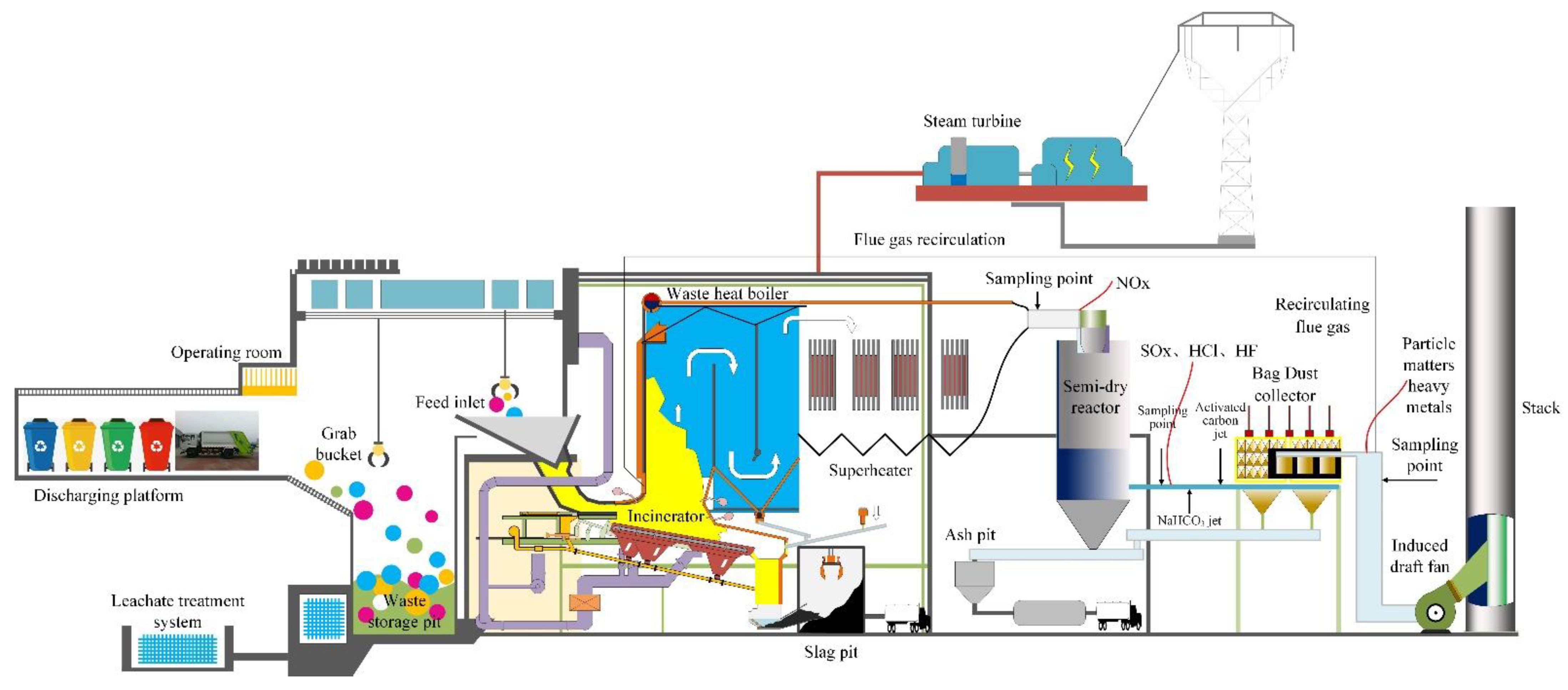
2.2. Plant Description

Located in Luoyang, China, the observed MSW incinerator power plant, whose waste treatment capacity was 500 tons per day, was put into operation in 2017. The process flow diagram of MSW incineration is shown in Figure 1. It primarily consisted of five subsystems: waste feeding, heat exchange, incinerator, waste heat boiler, and flue gas cleaning systems. The high-temperature flue gas produced by MSW combustion heated the feed water through heat transfer, generating superheated steam, which drove the steam turbine for further power generation. Then, after treatment by the flue gas cleaning system, the flue gas could be discharged to the atmosphere through the stack.
The flue gas cleaning system (see Figure 1) was designed to gradually decrease the flue temperature. The first step was the use of a semidry reactor using lime slurry (calcium hydroxide, Ca(OH)2 as the reactant) for the removal of acid gases such as HCl, HF, and SO2. Then, the flue gas was further treated by the dry method (sodium bicarbonate, NaHCO3 as the reactant) and activated carbon, which were injected into the flue gas duct before the bag filter, to remove the remaining acids, VOCs, dioxins, and heavy metals in the flue gas. The treated flue gas entered the bag filter for the removal of dust, followed by an extraction of waste heat from the flue gas by a heat exchange tube; finally, the purified flue gas was emitted into the air through the stack. Notably, FGR technology was adopted in this plant to inhibit the generation of NOx. The flue gas was extracted from the tail of the bag filter system and supplied to the corresponding part of the furnace instead of the secondary air. Due to the effectiveness of the technology, no further injection of urea solution was required under 100% maximum continuous rating (MCR) condition. However, the SNCR system was also installed for backup in case the FGR system was out of operation. The specifications of the main equipment and environmental protection facilities of this plant are listed in Table 2.

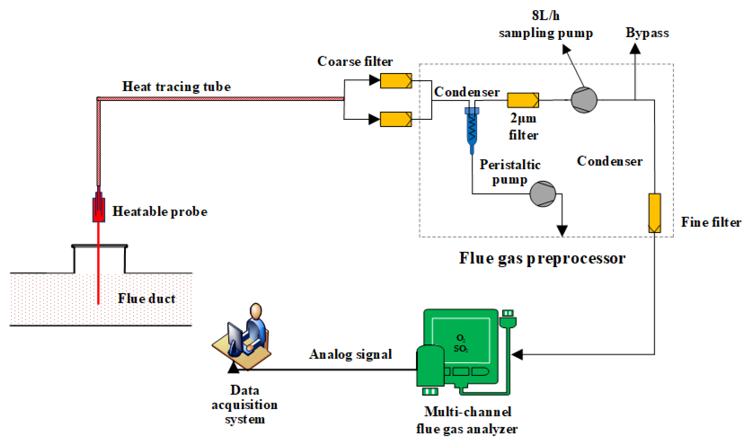
2.3. Sampling and Analysis

The sampling and test started after the combustion condition of the unit was stabilized for approximately 0.5 h, the test lasting for 6.0 h. To protect the monitoring instrument, pollutants emissions were consecutively sampled several times during the test. Usually, each test lasted 40 min with a 20 min cooling period for the instrument, and then we repeated the test, thereby obtaining 6 groups of sampled data during each test. The average value of the 6 groups of sampled data was used as the final result of the test, and the standard error of the measured values was recorded. To evaluate the flue gas cleaning system, the emission characteristics of acid gas, NOx, heavy metals, total organic carbon (TOC), and PM in the flue gas were considered. The unit was in normal operational condition when sampling and testing occurred on site.
We referred to the standard [22] for the sampling and testing of slag and ash. The detailed testing method of NOx was previously described [18]. In WTE power plants, NO accounts for more than 90% of the total NOx, so the NOx considered in the study was the concentration of NO. The SO2sampling and analysis method was determined according to the standard [23]. Because of the low dew-point characteristics of SO2, a heatable probe (model: PSP4000, M&C TechGroup, Ratingen, Germany) and heat-tracing tube were used to avoid the cryocondensation of SO2. The system diagram of SO2 sampling and analysis is shown in Figure 2. The sampling tube was inserted into the gas duct to extract flue gas from the rear flue. The extracted flue gas went through the heat-tracing tube and entered the flue gas preprocessor, then the concentrations of SO2 and O2 were measured by a multichannel flue gas analyzer (model: NGA2000-MLT3, Rosemount Inc., Shakopee, MN, USA). To analyze the emission levels of HCl and HF, an ion chromatograph (model: PIC-10A, Qingdao Puren Instrument Co., Ltd, Qingdao, China) was used according to the standard method EPA 26 [24]. For the measurement of PM, an automatic smoke sampler (model: 3012H, Xian Yima Optoelec Co., Ltd., Xi’an, China) and the parallel sampling method were used to collect the PM from the flue gas. Then, the filter cartridge was dried, cooled, and weighed, and the difference in its weight before and after sampling was the resulting value [25]. To analyze the levels of heavy metals, 10% H2O2 and 5% HNO3 solutions and an inductively coupled plasma-mass spectrometer (model: ICP-MS Agilent7500A, Agilent Technologies, Santa Clara, CA, USA) were used according to the standard method EPA 29 [26], and the TOC was measured according to the standard [27].

3. Results

3.1. Emission Level of NOx

The emission of NOx has been a major environmental problem as it is an acid rain precursor and can form photochemical smog [28,29], which seriously threatens human health and the environment. The control of NOx emission with the aid of MSW incinerators has attracted growing concern in recent years, especially as the regulations on pollutants emissions are becoming increasingly stringent. FGR technology was used in the power plant, and the NOx emission characteristics under different flow rates of recirculating flue gas were investigated. The combustion state and the NOx emission characteristics under different conditions are shown in Table 3. Notably, the SNCR system was out of operation in all conditions considered. The recirculating flue gas had a significant influence on the emission characteristics of NOx. The NOx emission concentration decreased from 209.54 to 126.15 mg/m3 as the FGR valve shifted from fully closed to fully open. When the FGR valve was fully closed, the NOx emission concentration was higher than the European Community (EC) emission limit [30] and the NOx emission limit of the plant, while it met the Chinese national standard (CNS) [31]. When the FGR valve was fully open, the NOx concentration met the three different emission limits, so the FGR valve was fully open in normal operation.

3.2. Emission Levels of Other Acid Gases

The semidry and dry techniques were used to reduce the acid gases in the power plant. The flue gas from the waste heat boiler entered the breeching of the spray reactor, in which a suitable spiral guide plate was arranged, spiraling clockwise downward. The lime slurry entered the high-speed rotating rotary atomizer, located on top of the spray reactor, and atomized the lime slurry into droplets with a diameter of about 50 μm. The droplets proceeded counterclockwise downward and a flue gas was formed, which was beneficial for the droplets and flue gas, and enhances the sorption of acid gases to promote the neutralization reaction. After treatment by the semidry technique, the flue gas was further treated by the dry technique, in which the NaHCO3 was injected into the outlet of the semidry reactor before the bag filter and the residual acid gases were further processed.
The emission concentrations of acid gases in the exhaust gas are listed in Table 4. The emission concentration of SO2 was 23.65 mg/m3, and those of HCl, HF, and TOC were 16.90, 0.58, and 0.62 mg/m3, respectively, all of which met the Chinese national standard [31]. However, the concentration of HCl was much higher than the EC emission limit [30] and the emission limit of the plant. So, other control technique for acid gases removal should be adopted or the existing device should be further improved.

3.3. PM Emission Levels

PM plays an important role in the formation of fog and haze [32]. In most Chinese cities, hazy weather has become a common phenomenon, especially in winter. Due to the aerodynamic diameter, most particles originating from power plants are inhalable (PM10, with a diameter of less than 10 μm) [33]. These particles can harm human health, and are one of the main factors influencing haze formation, which is inconvenient for human life such as leading to traffic accidents [33]. Thus, an effective and appropriate flue gas cleaning system should be selected.
In this power plant, the bag filter was selected for the removal of PM, for which the designed removal efficiency was 99.9%. In this investigation, the concentration of PM was 21.83 mg/m3, which was a little higher than the Chinese emission limit of 20 mg/m3 [31], and far beyond the EC emission limit (10 mg/m3) [30] and the plant’s requirement (8 mg/m3). Therefore, to meet the international emission standard, the appropriate dust removal technique should be applied or some measures should be adopted to enhance the performance of bag filters.

3.4. Emission Levels of Heavy Metals

The composition of MSW is complex, and most MSW is not diligently sorted before entering the incinerator. Some wastes with high contents of heavy metals, such as rubber, newspapers, plastics, and batteries, are incinerated together. Heavy metals are relatively toxic pollutants in the flue gas, which cannot be generated or destroyed in the incineration process, but can be migrated or transformed [34]. Some heavy metals exist in waste water, slag, or fly ash in a solid state, whereas others change from a solid into a gas state at high temperatures, and exist in the flue gas in the form of gas or attach to particulates in the flue gas [3]. In addition to being removed by a bag dust collector, the rest of the gaseous heavy metals are discharged into the atmosphere and remain for long periods, undegraded by microorganisms in the environment. The heavy metals enter the human body through the interaction of the atmosphere, water, and organisms, and continue to accumulate. After reaching a certain amount, they cause pathological changes in human tissues and organs, and result in serious harm through carcinogenesis and teratogenesis. Compared with the heavy metals in waste water, slag, and fly ash, heavy metals discharged into the atmosphere with flue gas are easily and passively absorbed by plants and breathed into the lungs of human due to their large diffusion and wide influence ranges [35]. Therefore, effective measures should be taken to reduce heavy metal emissions with flue gas during waste incineration treatment.
In the cleaning system studied, the flue gas entered the rotating spray reaction tower, where it was well-mixed with lime slurry. The heavy metal particulates in the flue gas accumulated through mutual collision, and the diameters gradually became larger and heavier, so the particulates were removed by the baghouse. Simultaneously, the temperature of the flue gas dropped to about 140 °C after passing though the reaction tower. Due to the cooling process, the vaporized heavy metals condensed to form fine particulates, which grew through impaction and agglomeration with the lime drops. Subsequently, the flue gas passed through the NaHCO3 and activated carbon injectors, and the heavy metals reacted with NaHCO3 to form precipitate or were adsorbed by porous activated carbon, which was further removed by the bag dust collector. Finally, the flue gas was discharged into the atmosphere through the stack. The emission concentrations of heavy metals are shown in Table 5. The concentrations of Hg and Cd + Ti were very low after passing through the cleaning system, which were far below the requirement in the regulations. However, the concentrations of Pb + Cr were a little high, at 0.21 mg/m3, although they met the emission limits.

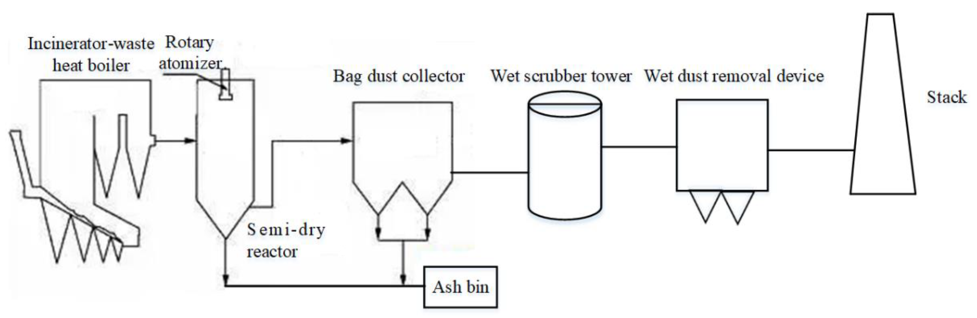
3.5. Improvement in Flue Gas Cleaning System

To further improve the performance of the cleaning system and reduce pollutant emissions, system optimization or retrofit should be adopted. Considering operation optimization, the air leakage rate, which is one of the main performance indices of flue gas cleaning equipment, was calculated by testing the flue gas volume at the inlet and outlet of the equipment [36], in this case at the rotating spray reaction towers and the bag dust collector. In our study, the test results showed that the air leakage rates of the rotating spray reaction tower and bag dust collector were 4.33% and 3.56%, respectively, which are somewhat higher than the designed value (2.00%). The performance of cleaning equipment is seriously affected if the air leakage rate is too large. Excessive cold air results in the local flue gas temperature falling below the dew point temperature, causing ash deposits, dew condensation, and corrosion, so measures should be taken to reduce the air leakage rate of equipment. To further reduce the emission concentrations of acid gases and PM, wet scrubbing and wet dust removal technologies can be adopted to meet the increasingly stringent environmental emission standards.
A wet scrubbing device is usually arranged behind the bag dust collector. The flue gas from the bag dust collector enters the wet scrubber tower through the bottom, the flue gas flows up and the alkaline solution (usually Ca(OH)2 or NaOH solution) flows down, so counter flow is formed, promoting the heat and mass transfer between the flue gas and alkaline solution, and the acid gas (SOx, HCl, HF, etc.) is removed through neutral reaction. The purified flue gas enters the downstream equipment after being defogged by the top defogger. The wet dust removal device is located behind the wet scrubber tower, in which the dusty gas can fully contact the water, and the PM in the flue gas can be separated from airflow by liquid wetting and adsorption as well as water surface tension and the static electric field. The simple flow chart of a modified flue gas purification system is shown in Figure 3.

4. Conclusions and Suggestions

The flue gas cleaning system in a WTE plant with FGR was investigated, and the main technologies and devices to control the emission concentrations of pollutants were introduced. The measured emission concentrations of pollutants were compared with the limits in legislative standards. The emission of NOx can be effectively reduced by adopting FGR technology, and the emission concentration of NOx can meet the international standards only by using FGR. The acid gases were significantly reduced, but the concentration of HCl was higher than the EC emission limit and the emission limit of the plant, although it may meet the CNC emission limit. The concentrations of heavy metals were low, whereas the concentration of PM was beyond the discharge limits at home and abroad.
As the environmental emission standards become more stringent, the system optimization or retrofit of the flue gas cleaning system should be adopted. The wet scrubbing and wet dust removal technologies proposed may further reduce emission concentrations to better achieve the goal of near-zero-emission.

Author Contributions

Conceptualization, W.W. and J.L. (Jun Liu); methodology, K.X.; validation, W.W. and J.L. (Jun Liu); formal analysis, Z.Z.; investigation, J.L. (Jisheng Long) and S.T.; resources, J.L. (Jisheng Long) and Q.M.; data curation, K.X.; writing—original draft preparation, W.W.; writing—review and editing, J.L. (Jun Liu); visualization, Z.Z.; supervision, W.W.; project administration, Q.M.; funding acquisition, W.W. All authors have read and agreed to the published version of the manuscript.

Funding

This research was funded by the Project of Central Plains Science and Technology Innovation Leading Talents of Henan Province, grant number 224200510022.

Institutional Review Board Statement

Not applicable.

Informed Consent Statement

Not applicable.

Data Availability Statement

Not applicable.

Conflicts of Interest

The authors declare no conflict of interest.

Appendix A

Table A1. Full names of all abbreviations.
Full NamesAbbreviationFull NamesAbbreviationFull NamesAbbreviationFull NamesAbbreviation
nitrogen oxideNOxCarbon dioxideCO2CadmiumCdCuprumCu
sulfur dioxideSO2Nitric oxideNOTitaniumTiManganeseMn
hydrogen chlorideHClCalcium hydroxideCa(OH)2LeadPbNickelNi
hydrogen fluorideHFSodium bicarbonateNaHCO3ChromiumCrVanadiumV
methaneCH4Hydrogen peroxideH2O2AntimonySbMercuryHg
oxygenO2Nitric acidHNO3ArsenicAs
carbon monoxideCOSodium hydroxideNaOHCobaltCo

References

  1. Wang, Z.D.; Teng, Y.; Hui, Q.; Chen, Z. A Sustainable Development Multi-energy System Planning Method Incorporating the Demand of Waste Disposal and Peak Shaving. Proc. CSEE 2021, 41, 3781–3797. [Google Scholar]
  2. Wang, G.; Deng, J.; Ma, Z.; Hao, J.; Jiang, J. Characteristics of filterable and condensable particulate matter emitted from two waste incineration power plants in China. Sci. Total Environ. 2018, 639, 695–704. [Google Scholar] [CrossRef] [PubMed]
  3. Su, X.; Zhang, L.; Xiao, Y.; Sun, M.; Gao, X.; Su, J. Evaluation of a flue gas cleaning system of a circulating fluidized bed incineration power plant by the analysis of pollutant emissions. Powder Technol. 2015, 286, 9–15. [Google Scholar] [CrossRef]
  4. Hu, Z.F.; Jiang, E.C.; Ma, X.Q. Numerical simulation on NOx emissions in a municipal solid waste incinerator. J. Clean. Prod. 2019, 233, 650–664. [Google Scholar] [CrossRef]
  5. Ho, W.S.; Hashim, H.; Lim, J.S.; Lee, C.T.; Sam, K.C.; Tan, S.T. Waste Management Pinch Analysis (WAMPA): Application of Pinch Analysis for greenhouse gas (GHG) emission reduction in municipal solid waste management. Appl. Energy 2017, 185, 1481–1489. [Google Scholar] [CrossRef]
  6. Lai, S.; Shi, Z.Q. How China views the EU in global energy governance: A norm exporter, a partner or an outsider? Comp. Eur. Polit. 2017, 15, 80–98. [Google Scholar]
  7. Hossain, H.Z.; Hossain, Q.H.; Monir, M.M.U.; Ahmed, M.T. Municipal solid waste (MSW) as a source of renewable energy in Bangladesh: Revisited. Renew. Sust. Energ. Rev. 2014, 39, 35–41. [Google Scholar] [CrossRef]
  8. Xi, J.P. Address at the General Debate of the seventy-fifth Session of the United Nations General Assembly. In Proceedings of the 75th Session of the United Nations General Assembly, New York, NY, USA, 23 September 2020. [Google Scholar]
  9. Wang, X.; Jia, M.; Lin, X.; Xu, Y.; Ye, X.; Kao, C.M.; Chen, S. A comparison of CH4, N2O and CO2 emissions from three different cover types in a municipal solid waste landfill. J. Air Waste Manag. Assoc. 2017, 67, 507–515. [Google Scholar] [CrossRef] [PubMed] [Green Version]
  10. Jafari, N.H.; Stark, T.D.; Thalhamer, T. Spatial and temporal characteristics of elevated temperatures in municipal solid waste landfills. Waste Manag. 2017, 59, 286–301. [Google Scholar] [CrossRef] [PubMed]
  11. Guo, H.; Duan, Z.; Zhao, Y.; Liu, Y.; Mustafa, M.F.; Lu, W.; Wang, H. Characteristics of volatile compound emission and odor pollution from municipal solid waste treating/disposal facilities of a city in Eastern China. Environ. Sci. Pollut. Res. 2017, 24, 18383–18391. [Google Scholar] [CrossRef] [Green Version]
  12. Edjabou, M.E.; Takou, V.; Boldrin, A.; Petersen, C.; Astrup, T.F. The influence of recycling schemes on the composition and generation of municipal solid waste. J. Clean. Prod. 2021, 295, 126439. [Google Scholar] [CrossRef]
  13. Zhu, Z.Z.; Wang, J.; Wang, P.L.; Zhong, L.; Xu, G.; Xu, Y.W. Analysis on Calorific Value of Municipal Solid Waste as Fired in China. Adv. New Renew. Energy 2021, 9, 110–114. [Google Scholar]
  14. Ding, G.; He, B.; Cao, Y.; Wang, C.; Su, L.; Duan, Z.; Song, J.; Tong, W.; Li, X. Process simulation and optimization of municipal solid waste fired power plant with oxygen/carbon dioxide combustion for near zero carbon dioxide emission. Energy Convers. Manag. 2018, 157, 157–168. [Google Scholar] [CrossRef]
  15. Lu, Q.; Zhou, X.-y.; Wu, Y.-w.; Mi, T.-g.; Liu, J.; Hu, B.; Zhao, L. Interaction mechanism between cadmium species and SiO2 of municipal solid waste incineration fly ash: Effect of HCl. Chem. Eng. J. 2021, 425, 130604. [Google Scholar] [CrossRef]
  16. Bruno, M.; Abis, M.; Kuchta, K.; Simon, F.-G.; Grönholm, R.; Hoppe, M.; Fiore, S. Material flow, economic and environmental assessment of municipal solid waste incineration bottom ash recycling potential in Europe. J. Clean. Prod. 2021, 317, 128511. [Google Scholar] [CrossRef]
  17. Wey, M.-Y.; Ou, W.-Y.; Liu, Z.-S.; Tseng, H.-H.; Yang, W.-Y.; Chiang, B.-C. Pollutants in incineration flue gas. J. Hazard. Mater. 2001, 82, 247–262. [Google Scholar] [CrossRef]
  18. Liu, J.; Luo, X.; Yao, S.; Li, Q.; Wang, W. Influence of flue gas recirculation on the performance of incinerator-waste heat boiler and NOx emission in a 500 t/d waste-to-energy plant. Waste Manag. 2020, 105, 450–456. [Google Scholar] [CrossRef]
  19. Liang, Z.Y.; Ma, X.Q. Mathematical modeling of MSW combustion and SNCR in a full-scale municipal incinerator and effects of grate speed and oxygen-enriched atmospheres on operating conditions. Waste Manag. 2010, 30, 2520–2529. [Google Scholar] [CrossRef]
  20. CJJ 90-2009; Technical Code for Projects of Municipal Waste Incineration. State Environmental Protection Administration of China: Beijing, China, 2009.
  21. Yi, H.; Hao, J.; Duan, L.; Tang, X.; Ning, P.; Li, X. Fine particle and trace element emissions from an anthracite coal-fired power plant equipped with a bag-house in China. Fuel 2008, 87, 2050–2057. [Google Scholar] [CrossRef]
  22. CJ/T 531-2018; Testing, Sampling and Sample Preparation of Slag and Ash from Waste Incinerator. Standards Press of China: Beijing, China, 2018.
  23. HJ 57-2017; Stationary Source Emission. Determination of Sulfur Dioxide. Fixed Potential by Electrolysis Method. China Environmental Press: Beijing, China, 2017.
  24. EPA method 26A; Determination of Hydrogen Halide and Halogen Emissions from Stationary Sources–Non-Isokinetic Method. U.S. Environmental Protection Agency: Washington, DC, USA, 2019.
  25. GB/T 16157-1996; Determination of Particulates and Sampling Methods of Gaseous Pollutants Emitted from Exhaust Gas of Stationary Source. State Environmental Protection Administration of China: Beijing, China, 1996.
  26. EPA Method 29; Determination of Metals Emissions from Stationary Sources. U.S. Environmental Protection Agency: Cincinnati, OH, USA, 2017.
  27. HJ 501-2009; Water Quality. Determination of Total Organic Carbon. Combustion Oxidation Nondispersive Infrared Absorption Method. China Environmental Science Press: Beijing, China, 2009.
  28. Jepsen, M.S.; Jensen, P.A.; Clausen, S.; Fateev, A.; Glarborg, P.; Norman, T. Measurements of the NOx precursors and major species concentrations above the grate at a waste-to-energy plant. Fuel 2018, 222, 475–484. [Google Scholar] [CrossRef]
  29. Yang, W.; Wang, B.; Lei, S.; Wang, K.; Chen, T.; Song, Z.; Ma, C.; Zhou, Y.; Sun, L. Combustion optimization and NOx reduction of a 600 MWe down-fired boiler by rearrangement of swirl burner and introduction of separated over-fire air. J. Clean. Prod. 2019, 210, 1120–1130. [Google Scholar] [CrossRef]
  30. Directive 2000/76/EC; Directive 2000/76/EC of the European Parliament and of the Council on the Incineration of Waste. European Commission: Brussels, Belgium, 2000.
  31. GB18485-2014; Standard for Pollution Control on the Municipal Solid Waste Incineration. State Environmental Protection Administration of China: Beijing, China, 2014.
  32. Takaoka, M.; Shiota, K.; Imai, G.; Oshita, K. Emission of particulate matter 2.5 (PM2.5) and elements from municipal solid waste incinerators. J. Mater. Cycles Waste Manag. 2016, 18, 72–80. [Google Scholar] [CrossRef]
  33. Anju Elizbath, P.; Shiva, N.S.M.; Indumathi, M.N. Comprehensive analysis of inhalable toxic particulate emissions from an old municipal solid waste dumpsite and neighborhood health risks. Atmos. Pollut. Res. 2018, 9, 1021–1031. [Google Scholar]
  34. Shi, Y.; Li, Y.; Yuan, X.; Fu, J.; Ma, Q.; Wang, Q. Environmental and human health risk evaluation of heavy metals in ceramsites from municipal solid waste incineration fly ash. Environ. Geochem. Health 2020, 42, 3779–3794. [Google Scholar] [CrossRef] [PubMed]
  35. Chen, L.M.; Liao, Y.F.; Ma, X.Q. Heavy metals volatilization characteristics and risk evaluation of co-combusted municipal solid wastes and sewage sludge without and with calcium-based sorbents. Ecotox. Environ. Safe. 2019, 182, 109370. [Google Scholar] [CrossRef] [PubMed]
  36. ASME PTC 4.3-2017; Air Heaters Performance Test Codes. The American Society of Mechanical Engineers: New York, NY, USA, 2017.
Figure 1. Schematic diagram of the MSW incinerator power plant.
Atmosphere 13 01016 g001
Figure 2. System diagram of SO2 sampling and analysis.
Atmosphere 13 01016 g002
Figure 3. Simple flow chart of a modified flue gas purification system.
Atmosphere 13 01016 g003
Table 1. The designed proximate and ultimate analysis of MSW.
MSWProximate Analysis (wt%) aUltimate Analysis (wt%) b
MoistureCombustible MatterAshLHV (kJ/kg)CHONSCl
Received44.3135.3820.31669954.557.7234.621.900.310.90
a As-received basis, ar. b As dry ash-free basis, daf.
Table 2. Specifications of the main equipment and environmental facilities.
Name of
Facility
ItemUnitParameter
Incinerator and waste heat boilerType of incinerator-Reciprocating mechanical grate furnace
Daily waste treatment capacityt/d500
Boiler rated evaporating capacity (MCR)t/h51.80
Rated steam pressureMPa4.00
Main steam temperature°C400
Denitrification systemType of denitrification system-SNCR + flue gas recirculation
Flow of recirculating flue gas m3/h0~26,240
Reagents of SNCR-Urea
Number of nozzle-12 (three layers arrangement)
Flow rate of urea (per nozzle)L/min3.2
Deacidification systemType-Semi-dry method (rotating spray reaction towers) + dry method (NaHCO3 injection) + activated carbon injection
Inlet temperature of semidry reactor°C190
Consumption of Ca(OH)2 (semidry method)kg/t MSW8.0
Consumption of NaHCO3 (dry method)kg/t MSW2.5
Consumption of activated carbonkg/t MSW0.5
Dust collectorType -Bag dust collector
Flue gas temperature°C155
Removal efficiency%>99.80
Dust content at outlet (11% O2, dry basis)mg/m3<8.00
Air leakage rate%2%
Table 3. The combustion and operation states of the boiler.
ItemUnitCondition 1Condition 2Condition 3
Opening of recirculating flue gas damper%100500
Flow rate of recirculating flue gasm3/h16,163.939345.650.00
Flue gas temperature at outlet of economizer°C193195198
CO2 emission concentration%14.0714.1313.92
CO emission concentration mg/m311.4811.309.56
NOx emission concentrationmg/m3126.15 ± 5.60178.90 ± 6.23209.54 ± 6.45
NOx emission limit of plant (daily average)mg/m3180.00
CNS emission limit [31] (daily average)mg/m3250.00
EC emission limit [30] (daily average)mg/m3200.00
Table 4. The emission concentrations of other acid gases in the flue gas.
Acid GasSO2HClHFTOC
Unitmg/m3mg/m3mg/m3mg/m3
Value23.65 ± 2.3116.90 ± 2.520.58 ± 0.060.62 ± 0.03
Emission limit of the plant (daily average)30.008.001.0010.00
CNS emission limit [31] (daily average)80.0050.00--
EC emission limit [30] (daily average)50.0010.001.0010.00
Table 5. The emission concentrations of heavy metals in the flue gas.
ElementHgCd + TiPb + Cr
Unitmg/m3mg/m3mg/m3
Value1.45 × 10−43.90 × 10−30.21
Emission limit of plant (daily average)0.050.050.50
CNS emission limit [31] (daily average)0.050.10 a1.00 b
EC emission limit [30] (daily average)0.050.05 c0.50 d
a The total concentration of Cd and Ti. b The total concentration of Sb, As, Pb, Cr, Co, Cu, Mn, and Ni. c The total concentration of Cd and Ti. d The total concentration of Sb, As, Pb, Cr, Co, Cu, Mn, Ni and V.
Publisher’s Note: MDPI stays neutral with regard to jurisdictional claims in published maps and institutional affiliations.

