Abstract
The cloud adjacency effect on surface reflectance retrievals for the region of the Russian Federation with coordinates 51–54, 103–109 including the southern part of Lake Baikal for the period of 1–23 July 2021 is assessed in this paper. The method is based on the computer program for statistical simulation of radiative transfer in the atmosphere with the stochastic cloud field including a deterministic gap of a given radius. The results of this program are then used in the interpolation formula. Masks of cloudless pixels, for which the cloud adjacency effect (CAE) changes the ground surface reflectance by more than 0.005, are constructed. The analysis of the resulting CAE radii shows that the average radius is 13.7 km for MODIS band 8, 11.2 km for band 3, 8.4 km for band 4, 7.2 km for band 1, and 7 km for band 2. For the considered MODIS images and bands, the pixels with strong CAE make up from 2.8 to 100% of the total number of cloudless pixels. The correlation coefficients between the initial data and the CAE radius suggest that the cloud optical depth, cloud cover index, and ground surface reflectance exert the major influence on the considered images. A simplified approximation equation for the CAE radius as a function of the cloud optical depth, cloud cover index, and surface reflectance is derived. The analysis of the approximation shows that for the considered images, the CAE radius decreases nearly linearly with wavelength for low reflective surfaces. However, for high reflective surfaces, its wavelength dependence is nonlinear.
1. Introduction
The consideration of the adjacency effect is important for solving the problem of atmospheric correction of satellite images in the visible and near-IR ranges. Ignoring the adjacency effect, it is impossible to obtain reliable satellite information on the ground surface reflectance for a wide range of optical-geometric conditions. The attempts to take the adjacency effect into account are undertaken for a long time. Several approaches are now developed for clear-sky situations [1,2,3,4,5,6,7]. However, for cloudy sections of satellite images, there are no ways for correct consideration of the side illumination from nearby clouds or the cloud adjacency effect (CAE) on the accuracy of retrieval of ground surface reflectance in the general case. Below we briefly consider the earlier approaches to the solution of this problem.
One of the limited model situations, when half of the ground surface is covered by a continuous cloud field and the sky above the other half is clear, is considered in work [8]. It is shown that the CAE in some situations extends to distances as long as 25 km. However, this limited case is by no means always observed, because cloud fields are often broken.
The adjacency effect from a single cloud shaped as a parallelepiped on reflectance retrievals is considered in work [9]. It is shown that for Landsat B1 band at nadir observation in a situation that the aerosol optical depth of a cloudless atmosphere is 0.2 and the cloud optical depth is 20, the CAE enhances the retrieved reflectance by 0.015 on the sunward side near a cloud and reduces it by a value up to 0.03 in the cloud shadow. Away from a cloud, the CAE decreases and reaches an asymptotic value of 0.005 at a distance of 2–3 km. For Landsat B7 band, at the aerosol optical depth of a cloudless atmosphere equal to 0 and the cloud optical depth of 20, the CAE increases the reflectance by 0.004 on the sunward side near a cloud and decreases the reflectance by 0.048 in the cloud shadow. At a distance of 3 km, the cloud adjacency effect on reflectance retrievals in this situation can be neglected. However, considering a single cloud, we overlook the horizontal transfer between clouds, which can change the effect of clouds on the accuracy of reflectance retrievals. In addition, for non-nadir observation, the CAE may be even larger than that estimated in [9].
The adjacency effect from a single cloud on the image of a water surface is considered in work [10], where it is proposed to retrieve the surface reflectance with allowance for the cloud shadow. This approach also cannot be considered as versatile, because it ignores the possible presence of several clouds in an image.
A deterministic approach to the cloud effect consideration is proposed in [11]. An inhomogeneous model of the medium is constructed based on the arrangement and size of clouds in the cloud field and the optical-geometric conditions. The Monte Carlo simulation of radiation transfer is performed for this model, and the dependence of the retrieved reflectance on the distance to the cloud field is calculated. For the first of the scenes considered, it was obtained that at a distance R = 4 km from the cloud field the cloudiness increases the retrieved reflectance by ∼ 0.01 at = 0.47 m and by ∼ 0.003 at = 0.66 m. For the second scene at a distance R = 8 km, ∼ 0.006 at = 0.47 m and ∼ 0.004 for = 0.66 m. However, this approach is poorly suited for real-time use in solving specific problems. In addition, the results, due to their particular character, cannot fully correspond to all possible situations.
Statistical analysis of images was performed in [12]. The analyzed data were used to obtain average reflectance values and their increments as functions of the distance to clouds for five MODIS bands. The cloud effect on reflectance extends, on average, to 15 km. The cloud effect near sunlit and shadowy sides of clouds is significantly different up to R = 4 km, but then the increments begin to behave similarly. This approach has the following shortcomings: (1) a wide spread of results caused by the wide variability of optical-geometric conditions, (2) the results are obtained only for the water surface and their extrapolation to land is hard due to the high horizontal inhomogeneity of the land surface.
A homogeneous field of model stochastic clouds in the form of randomly arranged parallelepipeds of the same size and the non-reflecting ground surface are considered in the work [13]. The cloud effect averaged over the cloud field on reflection retrievals is estimated. It is stated that in the case of a non-reflecting surface, the result weakly depends on the cloud size, but strongly depends on the cloud cover index . The realization-averaged effect of cloudiness on images of cloudless sections in the given field is estimated as a function of the optical depth and the cloud cover index. It is shown that the reflectance enhancement can reach ∼ 0.1 for high values of the cloud cover index (∼1) and the cloud optical depth (50).
The approach reported in [13] is modified in [14] based on the statement that for low reflective surfaces (with reflectance close to 0), the CAE changes linearly with wavelength in the visible range. Therefore, for such situations, it is sufficient considering the case of the smallest radiation wavelength. The approaches [13,14] are limited to low reflective surface (for example, water surfaces). In the general case of high reflective surfaces, the wavelength dependence of CAE may be nonlinear due to the increasing influence of multiple reflection and scattering in the “cloudiness–ground surface” system.
The adjacency effect from a continuous cloud layer in the spherical atmosphere with allowance for inhomogeneous reflection from the ground surface is considered in [15]. The approach generally similar to the approaches for cloudless situations [2,3] was proposed. However, the mathematical model [15] does not allow adequate consideration of the effect from broken cloudiness.
In our paper, [16], we have proposed the approach to estimation of the cloud adjacency effect averaged over realizations of the stochastic cloud field in gaps in the cloud field. This approach is free of the main shortcomings of the alternative approaches. It does not use a particular arrangement of clouds, which allows the pre-calculation of the CAE. It is not limited to particular values of surface reflectance and takes into account the broken character of cloud fields. Based on the program developed in [16], we have proposed the interpolation formula for assessing the radius of significant adjacency effect from clouds (the CAE radius) on the ground surface reflectance. The CAE radius is understood here as a distance to clouds, within which the CAE changes the ground surface reflectance by 0.005 and more. Below we consider the application of the developed approach to MODIS images of the region of the Russian Federation (RF) with coordinates 51–54 N, 103–109 E for the period of 1–23 July 2021.
2. Problem Formulation and Method of Solution
The proposed method is based on the model of radiation transfer in the stochastic cloud field [17,18]. Within the proposed model, we assume that the radiation is transferred in the plane “atmosphere–ground surface” system (Figure 1).
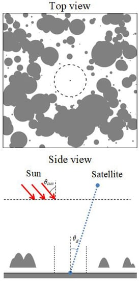
Figure 1.
Geometric of the problem.
The parallel flux of solar radiation is incident on the top of the atmosphere at the zenith angle . The statistically homogeneous Poisson cloud field is taken consisting of paraboloids. In the simulation, we used the algorithm for constructing Poisson fields in the form of paraboloids as described in [17]. The number of clouds is random and obeys the Poisson distribution [17]. The positions of cloud centers are random and corresponding to the uniform distribution in the plane Oxy. Cloud shapes are similar, while the cloud size is random and obeys the exponential distribution [17] with the mathematical expectation equal to the average horizontal cloud size . A deterministic cylindrical gap of radius R is set in the cloud layer. The cloud base is fixed and equal to = 1 km. The depth of a particular cloud is random, but the average depth is . The cloud cover index is taken to be . The aerosol optical characteristics are homogeneous in the cloud environment and described by the extinction and scattering coefficient and the scattering phase function. The optical model of cloudiness was constructed with the use of the OPAC cumulus cloud model [19]. The ground surface is homogeneous Lambertian with the reflectance . In this paper the reflectance is understood as the ratio of upward irradiance to downward irradiance. The satellite sensing system receiving radiation at the wavelength is located at the height . The optical axis of this system is directed to the ground surface point at the center of the surface projection of the cloud gap. The zenith angle of orientation of the optical axis of the receiving system is , and the azimuth angle between the directions toward the receiver and toward the sun from the observed point on the ground surface is .
The task is to assess the gap radius , at which the neglect of CAE on the results of sensing leads to the error in reflectance retrievals smaller than 0.005 and allows constructing the pixel mask, in which the error is larger than 0.005. On the first step the radiances received by the satellite system and averaged over an ensemble of realizations of the cloud field for the examined optical and geometrical conditions, the preset average reflectance are calculated by the backward Monte Carlo method with local estimations in each collision points depending on the gap radii R. If we neglect the cloud adjacency effect at the point on the ground surface corresponding to the projection of the center in the gap of the cloudy field, we obtain by the Monte Carlo method for horizontally homogeneous cloudless atmosphere the approximate value of the reflectance [16]. Then the gap radius for which the neglect of the cloud adjacency effect introduces the reflectance reconstruction error less than 0.005 is defined.
Within the mathematical model described in [16], we have developed the computer program based on the Monte Carlo method. To prove the reliability of the results obtained by our program, we have compared its results with the results for the test case [9], which considers the following situation: = 0.5 m, single rectangular 2 × 2 km cloud = 1 km thick, cloud base = 1 km, cloud optical depth = 20, aerosol optical depth of the cloudless atmosphere = 0.2, ground surface reflectance = 0.05, solar zenith angle = 30, solar radiation is directed along the axis Ox, zenith angle of the receiving system = . The observed points are located (a) along the axis x on the sunward side, (b) along the axis Oy. The task is to find the CAE from a single cloud on the reflectance. The results of comparison are shown in Figure 2. One can see that for the considered situations, despite the fact that our algorithm deals with paraboloid clouds, while in [9] clouds are shaped as parallelepipeds, the CAE from a single cloud changes the reflectance by close values for the same distances to the cloud field: the difference between the results does not exceed 0.0026. Along with the tests reported in our papers [16], this proves the reliability of the below results.
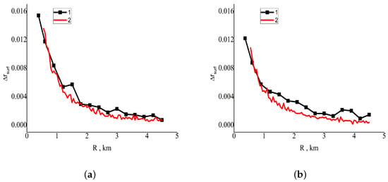
Figure 2.
Test comparison of the reflectance differences caused by a single cloud as functions of the distance to the cloud R: (1) results of [9] and (2) results of our program. (a) Observed points are located along the axis Ox on the sunward side; (b) observed points are located along the axis Oy.
With the developed program, mass calculations of the CAE radius for five MODIS bands and wide range of optical-geometric conditions were performed in [16]. As a result, the following interpolation formula was constructed:
where , , ⋯, are constants chosen so that the interpolation formula provides the results coinciding with the calculated ones at the nodes; is the average thickness of the cloud field, in km; is the cloud cover index; is the cosine of the solar zenith angle; is the cosine of the zenith angle of the receiving system; is the ground surface reflectance; is the aerosol optical depth of the cloudless atmosphere; is the cloud extinction coefficient.
To obtain the parameters needed for application of Equation (1), we use the data borrowed from the standard MODIS products, namely, the cloud mask, cloud optical depth and height (MOD06L2), aerosol optical depth of the cloudless atmosphere (MOD04L2), geometric parameters of observation (MOD03L2), and retrieved reflectances of the ground surface (MOD09L2).
3. Testing of the Algorithm for the Baikal Region
To test the proposed algorithm, we have considered the region of the RF with the coordinates 51–54 N, 103–109 E, which includes a part of Lake Baikal, for the period of 1–23 July 2021 (Figure 3). For this region, due to significant inhomogeneity of the ground surface and high average values of the cloud cover index, the consideration of the cloud adjacency effect is an important problem. The region under consideration was divided into 18 scenes by 1 × 1 coordinate grid. For each scene, the average (over the image) values of the following parameters were determined: , , , , , , . Then these values were substituted into interpolation Formula (1), and the CAE radius was estimated for various observation conditions. The variability range, average values, and standard deviations (SDs) for are given in Table 1 and Table 2 along with the initial values of the parameters. For the considered 18 scenes and five MODIS bands, Figure 4 shows the average values of . The value = 0 km means that the CAE changes the reflectances for all cloudless pixels by less than 0.005. It can be seen from Table 2 that the observed standard deviations for are rather large due to the widely variable observation conditions. From the results for , we can see that the average value of decreases with the wavelength . The decrease in the CAE radius with the wavelength was also observed, for example, in [14] for areas above the water surface.
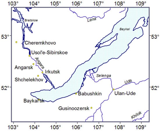
Figure 3.
Considered region of the RF with the coordinates 51–54 N, 103–109 E.

Table 1.
Initial values of the parameters , , , , and for the considered images.

Table 2.
Values of , , and for the considered images in different MODIS bands.
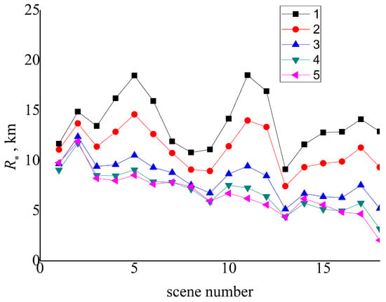
Figure 4.
Image-averaged radius of the cloud adjacency effect (CAE radius) for 18 scenes: (1) MODIS band 8, (2) MODIS band 3, (3) MODIS band 4, (4) MODIS band 1, and (5) MODIS band 2.
Using the obtained values of for all the considered bands and images, we have constructed the masks for pixels, in which the CAE changes the reflectance by > 0.005. Examples of the obtained masks for 05:00 UTC of 2 July 2021 and 03:40 UTC of 7 July 2021 are shown in Figure 5 and Figure 6.
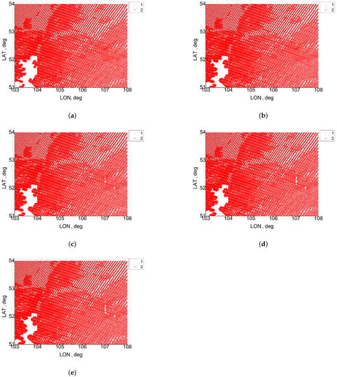
Figure 5.
Masks of the cloud adjacency effect (CAE) on reflectance retrievals from MOIDS data for 05:00 UTC of 2 July 2021: (a) MODIS band 8, (b) MODIS band 3, (c) MODIS band 4, (d) MODIS band 1, (e) MODIS band 2; (1) cloud points, and (2) cloudless points with strong CAE.
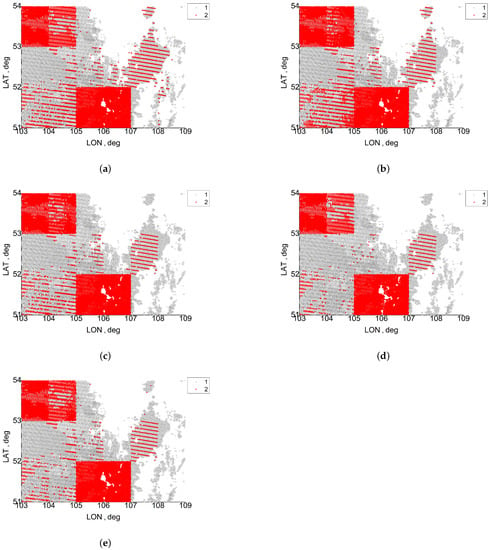
Figure 6.
Masks of the cloud adjacency effect (CAE) on reflectance retrievals from MOIDS data for 03:40 UTC of 7 July 2021: (a) MODIS band 8, (b) MODIS band 3, (c) MODIS band 4, (d) MODIS band 1, (e) MODIS band 2; (1) cloud points, and (2) cloudless points with strong CAE.
The resulting masks for other situations are given in the Supplementary Materials. Depending on an image and MODIS bands, the pixels with strong CAE make up from 2.8 to 100% of the total number of cloudless pixels. The analysis of the results for 2 July 2021, (Table 3) shows that the CAE radius varies from 4.5 to 38 km depending on the scene and MODIS band. Most of the surface under consideration is covered by clouds or zones with significant CAE. As can be judged from the satellite data, the CAE can be neglected only for a small part (Figure 7). As to the results of 7 July 2021 (Figure 6), the CAE radius ranges from 0 to 3.6 km depending on the scene and MODIS band. Thus, the CAE is significant for some scenes (scene 3, 4, 13, and 14 in Table 4), but small for the others. To understand the reasons for this behavior, it is sufficient to analyze the average cloud optical depths for the scenes (Table 4). The analysis shows that the cloud optical depth is small for the scenes with the small CAE radius.

Table 3.
Values of for five MODIS bands and 18 scenes on 2 July 2021. The data for scenes 6, 12, and 18 are omitted because of the lack of initial information on .
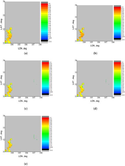
Figure 7.
Ground surface reflectances for the considered region at 05:00 UTC of 2 July 2021, from MOD09 data after rejection of pixels with strong CAE: (a) MODIS band 8, (b) MODIS band 3, (c) MODIS band 4, (d) MODIS band 1, and (e) MODIS band 2. The values from 0 to −0.1 correspond to the negative surface reflectance according to MOD09 data. The values smaller than −0.1 correspond to areas covered by clouds or with strong CAE.

Table 4.
Values of for five MODIS bands and 18 scenes on 7 July 2021.
As a result of using the mask shown in Figure 6, the sections with weak CAE were found. The reflectances for these sections are shown in Figure 8. One can see that for some sections the CAE radius is small. Therefore, there are surface sections observed through cloud gaps with weak CAE. In particular, a part of Lake Baikal is seen through gaps in the cloud field in Figure 8e.
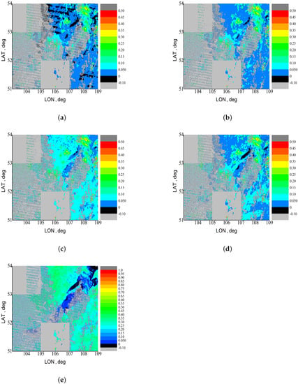
Figure 8.
Ground surface reflectances for the considered region at 03:40 UTC of 7 July 2021, from MOD09 data after rejection of pixels with strong CAE: (a) MODIS band 8, (b) MODIS band 3, (c) MODIS band 4, (d) MODIS band 1, and (e) MODIS band 2. The values from 0 to −0.1 correspond to the negative surface reflectance according to MOD09 data. The values smaller than −0.1 correspond to areas covered by clouds or with strong CAE.
Within the framework of used model (1), the function of seven variables is considered. However, the value of depends on them to varying degrees for the considered images. The Pearson correlation coefficients between and seven initial parameters were calculated for the five considered bands. The results are presented in Table 5. The analysis shows that the highest correlation coefficient is observed for the parameter . In addition, the correlation with and is significant. Therefore, for simpler analysis, we can consider the following approximation:

Table 5.
Coefficients of correlation of the initial parameters with the CAE radius.
The values of the approximation constants and average errors with respect to Equation (1) are given in Table 6.

Table 6.
Values of approximation constants of Equation (2) and average approximation errors for the considered bands.
The analysis of Table 6 shows that at close to 0, the CAE radius decreases almost linearly with wavelength, other things being equal (similarly to [14]). In addition, for the considered images, the influence of the reflectances on the CAE radius increases with wavelength.
4. Conclusions
In this study, the following results were obtained:
(1) Using interpolation Formula (1) developed on the basis of Monte Carlo calculations for broken clouds, we have estimated the cloud adjacency effect (CAE) radius and constructed masks of cloudless pixels, in which the CAE changes the surface reflectance by values greater than 0.005 for the RF area with coordinates 51–54, 103–109.
(2) The average CAE radius for the considered images was 13.7 km for MODIS band 8, 11.2 km for band 3, 8.4 km for band 4, 7.2 km for band 1, and 7 km for band 2.
(3) Depending on the image and MODIS bands, the pixels with strong CAE make up from 2.8 to 100% of the total number of cloudless pixels for the considered images.
(4) The analysis of correlation of the CAE radius with seven initial parameters has shown that CAE radius correlates most strongly with the cloud extinction coefficient , the average thickness of the cloud field , the cloud cover index , and the ground surface reflectance for the considered images.
(5) The simplified approximation (2) of the dependence of on , , , and was constructed. The results provided by this approximation differ from the results of Equation (1) by values from 5.6 to 1.8 km depending on the MODIS band.
(6) The analysis of the approximation constants in Equation (2) shows that for the low reflective surface the CAE radius decreases with wavelength nearly linearly. However, for surfaces with higher reflection, the wavelength dependence becomes increasingly nonlinear.
The reliability of the results is confirmed by comparisons with [9] for a single cloud, with the results for overcast clouds, and with the results for regularly spaced identical clouds in a checkerboard pattern in our paper [16].
The proposed approach has advantages over alternative methods. The use of the CAE radius averaged over cloud field realizations and the interpolation formula allows one to pre-calculate all possible basic situations. The proposed approach can be applied without any restrictions on the ground surface reflectance. The calculations by this approach account for 3D effects in broken clouds and multiple reflections from the ground surface. Outside the CAE radius calculated by our method, the cloud adjacency effect can be considered as small and the ground surface reflectance can be retrieved on the assumption of the cloudless atmosphere from, for example, MOD09 data or data of similar algorithms.
The approach is characterized by the following shortcomings and limitations: the constants in Equation (1) were obtained for the cloudless LOWTRAN mid-latitudinal summer model and the OPAC cumulus cloud model. In addition, it was assumed that the cloud base is fixed and the cloud optical properties are constant within the scene. If actual situations are far from these models, then the obtained CAE radius may differ significantly. In addition, the quality of the method depends on the quality of satellite information, in particular, on the reliability of the obtained cloud parameters.
The algorithm uses MODIS data on the aerosol optical depth averaged over a cloudless area and the area-averaged ground surface reflectance. However, these parameters are influenced by the cloud adjacency effect. We expect that their values are overestimated due to CAE. As a result, the CAE radius that is used in interpolation Formula (1) turns out to be overestimated too. In the future, we plan to modify the approach by using the algorithm twice, so that the initial data outside the CAE radius obtained at the first stage will be then used at the second stage.
The resulting simplified approximation Formula (2) is applicable for approximate estimation of the CAE radius in the considered images. The possibility of its application in other situations requires additional verification.
The choice of the study region was caused by two factors: (1) significant inhomogeneity of the ground surface and (2) high average value of the cloud cover index. The proposed approach has no explicit restrictions on the use for other territories of the globe.
The alternative studies (for example, [13,14]) present the corrections of the surface reflectance by accounting for the cloud adjacency effect . At the first stage, the approach proposed by us is used to calculate the values of averaged over cloud field realizations at the given cloud gap radius R. These values can potentially be used as a basis for atmospheric correction of cloudless pixels within the CAE radius. However, at small R, the values for a particular cloud field realization may differ widely from the average over cloud field realizations (for example, in the presence of shadow). In the following studies, interpolations with other levels of can be constructed to provide for the atmospheric correction of areas within the CAE radius.
Supplementary Materials
Constructed masks of cloudless pixels, in which the cloud adjacency effect changes the surface reflectance by values greater than 0.005 are available online: https://github.com/MarinaEngel/Atmosphere_2022 (accessed on 30 October 2022).
Author Contributions
Conceptualization, M.V.T. and V.V.B.; methodology, M.V.T.; software, M.N.Z. and M.V.E.; validation, M.N.Z. and M.V.T.; investigation, M.V.E. and M.V.T.; resources, M.V.E.; writing—original draft preparation, M.V.T. All authors have read and agreed to the published version of the manuscript.
Funding
The work was supported by the Ministry of Science and Higher Education of the Russian Federation, the grant No. 075-15-2020-787 for implementation of Major scientific projects on priority areas of scientific and technological development (the project «Fundamentals, methods and technologies for digital monitoring and forecasting of the environmental situation on the Baikal natural territory»).
Institutional Review Board Statement
Not applicable.
Informed Consent Statement
Not applicable.
Data Availability Statement
https://github.com/MarinaEngel/Atmosphere_2022 (accessed on 30 October 2022).
Conflicts of Interest
The authors declare no conflict of interest.
References
- Tanre, D.; Herman, M.; Deschamps, P.Y.; de Leffe, A. Atmospheric modeling for space measurements of ground reflectances, including bidirectional properties. Appl. Opt. 1979, 18, 3587–3594. [Google Scholar] [CrossRef] [PubMed]
- Vermote, E.F.; El Saleous, N.Z.; Justice, C.O. Atmospheric correction of MODIS data in the visible to middle infrared: First results. Remote Sens. Environ. 2002, 83, 97–111. [Google Scholar] [CrossRef]
- Breon, F.M.; Vermote, E. Correction of MODIS surface reflectance time series for BRDF effects. Remote Sens. Environ. 2012, 125, 1–9. [Google Scholar] [CrossRef]
- Kotchenova, S.Y.; Vermote, E.F. Validation of a vector version of the 6S radiative transfer code for atmospheric correction of satellite data. Part II. Homogeneous Lambertian and anisotropic surfaces. Appl. Opt. 2007, 46, 4455–4464. [Google Scholar] [CrossRef] [PubMed]
- Lyapustin, A.; Martonchik, J.; Wang, Y.J.; Laszlo, I.; Korkin, S. Multiangle implementation of atmospheric correction (MAIAC): 1. Radiative transfer basis and look-up tables. J. Geophys.-Res.-Atmos. 2011, 116, D03210. [Google Scholar] [CrossRef]
- Tarasenkov, M.V.; Zimovaya, A.V.; Belov, V.V.; Engel, M.V. Retrieval of Reflection Coefficients of the Earth’s Surface from MODIS Satellite Measurements Considering Radiation Polarization. Atmos. Ocean. Opt. 2020, 33, 179–187. [Google Scholar] [CrossRef]
- Lisenko, S.A. Atmospheric Correction of Multispectral Satellite Images Based on the Solar Radiation Transfer Approximation Model. Atmos. Ocean. Opt. 2018, 31, 72–85. [Google Scholar] [CrossRef]
- Nikolaeva, O.V.; Bass, L.P.; Germogenova, T.A.; Kokhanovsky, A.A.; Kuznetsov, V.S.; Mayer, B. The influence of neighbouring clouds on the clear sky reflectance studied with the 3-D transport code RADUGA. J. Quant. Spectrosc. Radiat. Transf. 2005, 94, 405–424. [Google Scholar] [CrossRef]
- Cahalan, R.F.; Oreopoulos, L.; Wen, G.; Marshak, A.; Tsay, S.-C.; DeFelice, T. Cloud characterization and clear-sky correction from Landsat-7. Remote Sens. Environ. 2002, 78, 83–98. [Google Scholar] [CrossRef]
- Reinersman, P.N.; Carder, K.L.; Chen, F.-I.R. Satellite-sensor calibration verification with the cloud-shadow method. Appl. Opt. 1998, 37, 5541–5549. [Google Scholar] [CrossRef] [PubMed]
- Wen, G.; Marshak, A.; Cahalan, R.F.; Remer, L.A.; Kleidman, R.G. 3-D aerosol-cloud radiative interaction observed in collocated MODIS and ASTER images of cumulus cloud fields. J. Geophys. Res. 2007, 112, D13204. [Google Scholar] [CrossRef]
- Varnai, T.; Marshak, A. MODIS observations of enhanced clear sky reflectance near clouds. Geophys. Res. Lett. 2009, 36, L06807. [Google Scholar] [CrossRef]
- Marshak, A.; Wen, G.; Coakley, J.A., Jr.; Remer, L.A.; Loeb, N.G.; Cahalan, R.F. A simple model for the cloud adjacency effect and the apparent bluing of aerosols near clouds. J. Geophys. Res. 2008, 113, D14S17. [Google Scholar] [CrossRef]
- Marshak, A.; Evans, K.F.; Varnai, T.; Wen, G. Extending 3D near-cloud corrections from shorter to longer wavelengths. J. Quant. Spectrosc. Radiat. Transf. 2014, 147, 79–85. [Google Scholar] [CrossRef]
- Sun, B.; Schäfer, M.; Ehrlich, A.; Jäkel, E.; Wendisch, M. Influence of atmospheric adjacency effect on top-of-atmosphere radiances and its correction in the retrieval of Lambertian surface reflectivity based on three-dimensional radiative transfer. Remote Sens. Environ. 2021, 263, 112543. [Google Scholar] [CrossRef]
- Tarasenkov, M.V.; Zonov, M.N.; Engel, M.V.; Belov, V.V. A Method for Estimating the Cloud Adjacency Effect on the Ground Surface Reflectance Reconstruction from Passive Satellite Observations through Gaps in Cloud Fields. Atmosphere 2021, 12, 1512. [Google Scholar] [CrossRef]
- Zuev, V.E.; Titov, G.A. Modern Problems of Atmospheric optics: V.9 Atmospheric Optics and Climate; Spectrum: Tomsk, Russia, 1996; p. 272. [Google Scholar]
- Titov, G.A. Statistical Description of the Transfer of Optical Radiation in Clouds. Dis.… doct. Physical-Mat; IOA SB AS USSR: Tomsk, Russia, 1988; 361p. [Google Scholar]
- Hess, M.; Koepke, P.; Schult, I. Optical Properties of Aerosols and Clouds: The Software Package OPAC. Bull. Am. Meteorol. Soc. 1998, 79, 831–844. [Google Scholar] [CrossRef]
Publisher’s Note: MDPI stays neutral with regard to jurisdictional claims in published maps and institutional affiliations. |
© 2022 by the authors. Licensee MDPI, Basel, Switzerland. This article is an open access article distributed under the terms and conditions of the Creative Commons Attribution (CC BY) license (https://creativecommons.org/licenses/by/4.0/).