Abstract
The streamer bursts generated during the initiation and propagation of leaders play an important role in the creation and maintenance of hot discharge channels in air. The most important parameters related to streamer bursts in this respect are the length of the streamer bursts, their lateral extent and the charge associated with them. The lateral extent of the streamer bursts may play a significant role in deciding the path and the tortuosity of the discharge channels of laboratory discharges and lightning. The charges associated with the streamer bursts are needed in understanding the physical processes associated with the streamer-to-leader transition. In this paper, the length, the lateral extension and the charge of the streamer regions generated by grounded conductors when exposed to external electric fields are estimated. This estimation is based on two assumptions: (i) once a streamer is incepted, the streamer head follows the direction of maximum background electric field at the location of the streamer head and (ii) the streamer continues to extend along this direction until the potential drop along the streamer channel matches the potential drop caused by the background electric field between the initial and end points of the streamer channel. The same technique could be used to estimate the streamer bursts generated in laboratory discharges and lightning stepped leaders. It is shown that in estimating the geometry of the streamer region, it is necessary to include the spread of streamers caused by branching. Moreover, the charge associated with the streamer region increases as the frequency of branching increases. The results obtained confirm that the charge in the streamer region can significantly change the potential ahead of the streamer region from the background potential and this has to be taken into account in any study that simulates the initiation and propagation of lightning leaders. Since the streamer bursts of leaders control the direction and speed of the leaders, the technique we have used here could be implemented in lightning leader progression models.
1. Introduction
The electrical discharge processes taking place in air can be separated into electron avalanches, streamer discharges, leader discharges and return strokes [1,2,3,4]. In laboratory gaps excited by lightning impulse voltages, the breakdown process is mediated mainly by streamer discharges [5,6], whereas in laboratory gaps excited by switching impulse voltages and in lightning discharges, the breakdown process is mediated by leaders assisted by streamer discharges [1,2]. Thus, understanding the physical processes that give rise to streamer discharges and leaders is important both in understanding the electrical breakdown in long laboratory sparks and in lightning. Furthermore, in problems related to lightning attachment to grounded structures, the creation of upward-connecting leaders from the grounded structures in response to down-coming leaders is mediated by streamer discharges generated by the grounded structure under the influence of the high electric field created by the down-coming leaders [7,8,9]. Moreover, the propagation of leaders of both polarities is also mediated by streamer discharges generated from the tips of these propagating leaders [1,10,11]. Thus, the knowledge on the geometry, the spatial extension and the charge associated with the streamer discharges issued from grounded structures, high voltage electrodes or lightning leaders is important in understanding the breakdown process in laboratory sparks excited by lightning impulses or in understanding the initiation and propagation of leader discharges both in laboratory and in lightning.
In this paper, we will study the streamer region generated by grounded conductors when exposed to high electric fields. We will concentrate mainly on the positive streamers because the majority of lightning discharges carry negative charge to ground, and the connecting leaders issued by grounded conductors in response to down-coming lightning leaders are led by positive streamer discharges [12]. However, the same procedure that we use here can be used to estimate the extension, geometry and charge of negative streamer bursts issued from grounded conductors and negative or positive streamer regions of long laboratory sparks and lightning leaders.
2. Streamer Region
As mentioned in the introduction, when a grounded conductor is exposed to an electric field or when a high voltage electrode is raised to a high potential, a streamer burst is created from the tip of the relevant conductor. Here, we will estimate the extension, the width and the charge associated with the streamer burst. In order to evaluate how far the streamers will travel from the tip of the conductor, we will be making four assumptions which have already been used in studies related to streamers. They are the following: (1) Streamer inception takes place when the number of positive ions on an avalanche reaches a critical value of 108. (2) Streamers propagate in the direction of maximum electric field ahead of the streamer tip [13,14]. (3) The potential gradient along the positive streamer channels is approximately 500 kV/m and that of negative streamer channels is 1 MV/m [1,2,3]. (4) The streamers propagate up to a distance where the integral of the potential gradient along the streamer channels is equal to the integral of the background field along the path of the streamer channel [7,8,9]. In this procedure, the direction of the electric field lines controls the path of streamers, and the strength of the electric field controls the extension of the streamers. This fourth condition mentioned above can be illustrated using the diagram in Figure 1. Let the curve marked ‘a’ be the variation of the background potential as one moves away from the tip of a conductor. This curve is obtained by first obtaining the background electric field in the presence of the rod by the charge simulation method and from that electric field the potential as a function of distance from the tip of the rod. Note that the tip of the rod is at ground potential. The curve marked ‘b’ gives the integral of the potential gradient of the streamer channels along their path. The length of the streamer burst is given by the distance OP where O is the origin of the streamer burst (i.e., the tip of the conductor) and P is the point where curve ‘b’ meets curve ‘a’. With these four assumptions, once the location and the orientation of the initiation of the streamer channel are given, one can trace its path if the background electric field is known. Observe that streamers can be initiated from different places on the tip of the conductor and the path of a given streamer channel depends on the point on the tip of the conductor from where the streamer is initiated. In the analysis, we assume that the tip of the conductor is of hemispherical shape and streamers could be initiated from any point on this hemisphere. Since the electric field at the surface of a conductor is perpendicular to its surface, it is reasonable to assume that the direction of initiation of the streamers is perpendicular to the hemispherical surface. The streamers leaving the pole of the hemisphere (i.e., from the tip of the conductor or along the symmetry axis) follow a straight path, while the ones leaving the hemisphere from different points will follow a curved path. In the analysis, we assume that the majority of the streamers will leave the hemisphere at locations above the equator and only a few, if any, will leave from points below the hemisphere. This is the case because the electric field decreases rapidly as one goes below the equator. Figure 2 shows the path of streamers leaving the conductor at different polar angles. In this calculation, the radius of the rod was assumed to be 2 cm. Observe that the streamers leaving the equator (polar angle 90 degrees) will define the outer boundary of the streamer region.
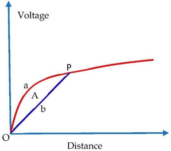
Figure 1.
The distance–voltage diagram depicting the procedure to obtain the length of the streamer region. The curve marked ‘a’ gives the potential ahead of the tip of the rod marked ‘O’ caused by the background electric field. The curve marked ‘b’ defines the line with a potential gradient identical to that of the streamer channel. The two curves cross each other at P and the area between the two curves is denoted by ‘A’.
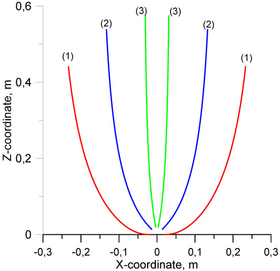
Figure 2.
The path of the streamer channels leaving the tip of the rod, which is formed as a hemisphere, at different polar angles. The path marked (1) is taken by the streamers leaving the equator of the hemisphere (polar angle 90 degrees). The curves marked (2) and (3) correspond to the paths of streamers leaving the hemisphere with polar angles of 45 and 10 degrees. Observe that zero degree corresponds to the streamer leaving from the top of the hemisphere. Note that what is depicted is the cross section of the three-dimensional streamer zone, which is symmetric around the central axis. The height of the grounded rod is 2.5 m, the radius of the rod is 2 cm and the value of the (vertical) background electric field is 100 kV/m.
2.1. Effect of Streamer Branching
In the results presented in the last section, it was assumed that once initiated, the streamers follow the background electric field without branching until they exhaust the background potential available to them. However, experimental data show that propagating streamers frequently branch [14,15]. The quantitative analysis presented in references [14,15] shows that the free path of streamers between branching (henceforth referred to as branching length) is in the order of millimeters. The exact value may depend on the diameter of streamers and the background electric field. However, most of the free paths are distributed between 2 mm and 10 mm. Moreover, the most frequent branching angle of streamers was found to be approximately 45°. This information is incorporated into the present study as follows. We assume that the branching length of streamers varies between 2 to 10 mm. In a given calculation, we keep the branching length of the streamers constant. However, results will be shown for different values of branching lengths. We also assume that the branching angle remains constant at 45°. In our study, we are interested in the outer boundary of the streamer region. Thus, the motion of the streamer leaving the equator of the semi-spherical tip is of interest. As this streamer branches, the two branches can be directed at any azimuth angle with respect to the original streamer channel. However, since the region between this streamer and the streamer following the symmetry axis of the conductor is filled with space charge, due to electrostatic repulsion there is a high probability for one of the branches to be directed outwards. The outer boundary of the streamer region is defined by the streamer channel generated by the outward branching of the streamer channels. In the calculations, we assume that the branching of the streamer channel is such that one of the branches is always directed out of the space-charge region (see Figure 3). In a way, this assumption gives rise to the maximum possible lateral spread of the streamer region. The streamer regions calculated by incorporating streamer branching as described above are shown in Figure 4. Note that the paths shown are for streamers leaving the equator of the hemisphere but for different branching lengths. Observe how, depending on the branching length, the width of the streamer region increases in comparison to the situation without branching. The smaller the branching length, the larger will be the width and, hence, the volume of the streamer region.
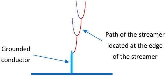
Figure 3.
Illustrating the procedure (exaggerated) used to identify the outer edge of the streamer region. It is assumed that whenever the streamer branches, one of the branches is always directed away from the axis of the conductor.
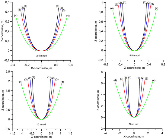
Figure 4.
The outer extremity of the streamer zone generated by rods of different heights (marked in the plots), of 2 cm radius, when exposed to an electric field of 100 kV/m. The different curves correspond to different streamer branching lengths. The curves marked (1) in the diagram correspond to streamers moving without branching. Curves (2–4) correspond to branching lengths of 10 mm, 5 mm and 2 mm, respectively.
2.2. Comparison of the Calculated Streamer Region with Experimental Observations
Experimental data on the geometry of the first streamer burst generated by lightning rods exposed to thundercloud electric fields are not available in the literature. However, a few examples of the streamer region generated by long laboratory sparks that could be used to test the theoretical predictions are available in the literature. If the gap length, the geometry of the high voltage electrode and the applied voltage are given, one can use the same procedure used earlier to calculate the streamer region of grounded conductors to obtain the geometry of the streamer region generated by the high voltage electrodes. For example, Figure 5 shows the geometry of the streamer bursts generated by high voltage electrodes when raised to a given potential. As in the previous examples, we have used different branching lengths to obtain the outer region of the streamer bursts. In the calculation, we have assumed that the grounded electrode is a flat plane (i.e., we have considered a rod-plane gap). Again, note that the width of the streamer region increases with decreasing branching length.
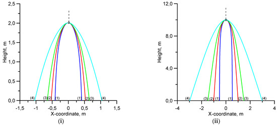
Figure 5.
Streamer region of rod-plane gaps of (i) 2-m gap excited by 2 MV and (ii) 10-m gap excited by 10 MV. The curve (1) corresponds to no streamer branching and curves (2), (3) and (4) correspond to streamer branching lengths of 10 mm, 5 mm and 2 mm, respectively. The radius of the rod is 2 cm.
One of the best examples we have found in the literature that shows the streamer region generated by a high voltage electrode was published by Bogatov et al. [10]. In this example, a rod-plane gap of 5.5 m was raised to a potential of 5 MV. The radius of the high voltage electrode was 5 cm. The streamer regions calculated for this gap for different branching distances are shown in Figure 6, together with the experimental data published by Bogatov et al. [10]. One can observe a short leader section also in the gap, but its length is short in comparison to the gap length. Close examination of this photograph shows that the streamer region is confined almost within the boundary of the curves corresponding to 5 mm and 10 mm branching. Note that the streamer region is displaced slightly to the right and for this reason one may get the impression that a small part of the streamer region spreads out of this boundary. From this comparison, one may conclude that there is a good agreement between the calculation and experimental observation for a branching distance of approximately 5–10 mm.
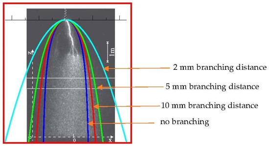
Figure 6.
A photograph of the streamer zone of a 5.5-m rod-plane gap with an applied voltage of 5 MV as published by Bogatov et al. [10]. The four curves shown in the diagram correspond to the following cases. Blue: No branching; red: 10 mm branching distance, green: 5 mm branching distance and turquoise: 2 mm branching distance.
2.3. Charge on the Streamer Region
One parameter which is of interest in analyzing the initiation of leaders from grounded conductors is the charge associated with the streamer region. For example, in the literature, it is documented that if the charge in the streamer region exceeds approximately 1 μC, it will lead to the streamer-to-leader transition [1]. The charge in the streamer region can be estimated by using the charge simulation method and assuming that the potential gradient inside the streamer region remains at a constant value equal to the potential gradient of the streamer channels. The charge in the streamer region is calculated for different branching lengths and the results are presented in two ways in Figure 7. Figure 7i presents the streamer charge as a function of the area between the two potential curves, one representing the background potential as a function of distance and the other representing the potential along the streamer channels in a distance–voltage diagram. These two curves are presented already in Figure 1 and the area between the two curves are marked as ‘A’. Figure 7ii depicts the streamer charge as a function of the length of the streamer region. Note that results are shown for cases where streamers propagate without branching and for streamer branching lengths of 10 mm, 5 mm and 2 mm. Observe how the charge in the streamer region increases with decreasing branching length.
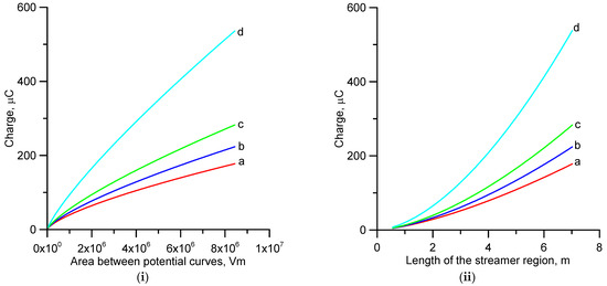
Figure 7.
(i) The best fit curves for the charge in the streamer region versus the area between the two potential curves, as illustrated in Figure 1. (ii) The best fit curves for the charge in the streamer region versus the length of the streamer region. (a) Without branches; (b) branching length 10 mm; (c) branching length 5 mm; (d) branching length 2 mm.
It is of interest to mention here that in the studies conducted previously, it was assumed that the charge in the streamer burst is proportional to the area ‘A’ (in Vm) described in the previous paragraph and marked in Figure 1 [7,8,9]. Analyzing this problem further, Becerra and Cooray [7] estimated that this proportionality constant is approximately 3.6 × 10⁻¹¹ C/Vm. Since we have found that a branching length of 5 mm gives a reasonable fit to the lateral extension of the streamer region, we will use a 5 mm branching length as a representative value in obtaining the charge in the streamer region. The data points obtained corresponding to a 5 mm branching length together with two best fit lines, one power fit and the other linear fit going through the origin are shown in Figure 8. Note that power fit represents the data better and the linear fit is a reasonable approximation. The power fit for the charge (in Coulombs) versus area (in Vm) is given by
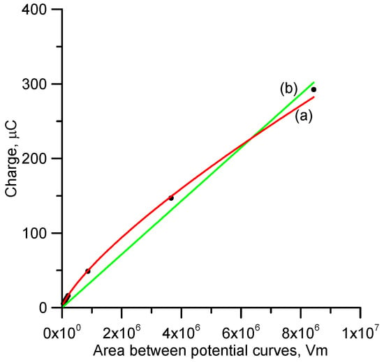
Figure 8.
Best fit curves (a) exponential fit and (b) linear fit to the charge versus the area between the potential curves corresponding to a streamer branching length of 5 mm. The actual data points are also shown in the diagram.
In the above equation, A is the area shown in Figure 1. The straight line fit for the data is given by
This is in good agreement with the results obtained by Becerra and Cooray [7].
2.4. The Potential Gradient Ahead of the Streamer Region
In the studies conducted previously [7,8,9], it is assumed that once a streamer burst is generated, the potential ahead of the streamer region remains more or less the one corresponding to the background electric field. In other words, it is assumed that the charge in the streamer region does not influence the background potential located ahead of the streamer region. In order to test this assumption, we have calculated the potential ahead of the streamer region after the generation of the streamer burst. The results together with the background potential are shown in Figure 9. Note that the charge in the streamer region can significantly change the potential ahead of the streamer region. This indicates that one cannot neglect the effect of the streamer region in further continuation of the propagation of the leader channel. Actually, this fact was previously pointed out by Bazelian and Raiser [16] and our study confirms it. This fact, together with the observation that subsequent streamer bursts can occur at another angle to avoid the previous streamer region, has to be taken into account in numerical simulations of the propagation of leaders [17].
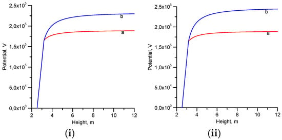
Figure 9.
The potential ahead of the streamer region as a function of the distance for (i) a 2.5 m rod, 100 kV/m, without branching and (ii) a 2.5 m rod, 100 kV/m, with 5 mm branching length. The curve ‘a’ depicts the background potential that existed before the generation of the streamer burst and curve ‘b’ depicts the potential after the creation of the streamer burst.
2.5. Summary of the Assumptions and the Procedure Used in Estimating the Streamer Region of Lightning Rods Exposed to a Background Electric Field
In this paper, a procedure to obtain the streamer region generated by a lightning rod when exposed to a background electric field is presented. The procedure used in the paper to obtain the geometry of the streamer region can be summarized as follows:
- (1)
- The electric field in the presence of the lightning rod is calculated using the charge simulation method.
- (2)
- It is assumed that inception of streamers from the rod takes place when the number of positive ions in the electron avalanches reaches a critical value of 108.
- (3)
- Once incepted, streamer heads follow the direction of the maximum electric field at the location of the streamer head.
- (4)
- The streamers continue to propagate until the potential drop along the streamer channel is equal to the potential drop between the point of initiation and the current location of the streamer head caused by the background electric field.
- (5)
- Based on available experimental data, it is assumed that streamers branch at intervals of 2 mm to 10 mm of propagation distances.
- (6)
- Based on experimental data, the branching angle is assumed to be 45°.
- (7)
- Once the geometry of the streamer region is obtained, the total charge in the streamer region is calculated using the charge simulation method assuming that the potential gradient inside the streamer region is equal to the experimentally obtained streamer potential gradient of 500 kV/m for positive streamers.
3. Discussion
In the analysis presented in this paper, we have kept the streamer branching distance constant as the streamer extends outwards and into the low field region. In other words, we assume that it is independent of the background electric field. However, the streamer branching length could depend on the background electric field and it also depends on the streamer diameter. The background electric field decreases as one moves away from the tip of the rod and one can expect the streamer diameter to also change as the streamer extends in the gap [14,15]. Thus, the agreement between 5 mm branching length and the observed streamer region cannot be considered as confirmation of the idea that the streamer branching length remains constant at this value throughout the propagation of the streamer. The 5 mm branching length has to be considered as an effective value that provides a reasonable fit to the experimental data. However, more experimental data are needed to support this conclusion.
In the analysis, it is assumed that streamers will follow the electric field lines of the background electric field. Of course, in the presence of branching, the new streamer heads associated with the two branches will follow electric field lines associated with the new location of the respective streamer heads. This assumes, in turn, that the orientation of the streamer in the high field direction is instantaneous. This may not be the case in reality. It is possible that there is some ‘momentum’ in the streamer channels that forces it to continue its travelling in the same direction and, if this is the case, it may take some time for the streamer to get oriented in the direction of the maximum electric field. This point also needs further consideration.
In long laboratory sparks, the hot spark channel results from the thermalization of the streamer channels created during the application of the high voltage. Therefore, the path of the discharge channel should coincide with the path of some of the streamer channels generated in the gap. Thus, if a spark gap experiment is repeated multiple times, the outer edge of the spark channels should coincide roughly with the outer edge of the streamer channels generated in the gap. This will allow a test of the validity of the results presented here using the path of discharge channels in long gaps.
It is important to point out that the predictions of the theory presented here could be confirmed under field conditions by the use of sufficiently high-resolution, high-speed cameras placed close to the tips of lightning rods or instrumented towers. Moreover, the procedure presented here, can be used to evaluate the spatial extent of the streamer region associated with stepped leaders. Since the length and the charge of the streamer region controls the stepping process, the theory outlined here could be used to improve the leader progression models [7,18,19].
4. Conclusions
The results presented here show that in estimating the geometry of the streamer region generated by grounded conductors when exposed to electric field or high voltage electrodes when raised to high voltages, it is necessary to include the spread of streamers caused by the branching. The scanty information available in the literature indicates that a branching distance of approximately 5 mm and a branching angle of approximately 45° provide a reasonable agreement with experimental observations.
The charge in the streamer region obtained with 5 mm branching length shows that it is reasonable to assume that the charge is proportional to the area between the background potential curve and the line that defines the streamer gradient in a voltage–distance diagram. The proportionality constant obtained is in reasonable agreement with previous estimates.
Author Contributions
Conceptualization, V.C.; Methodology, V.C.; Validation, V.C., H.J., M.R. and F.R.; Writing—original draft, V.C. and H.J.; Writing—review & editing, V.C., H.J., M.R. and F.R. All authors have read and agreed to the published version of the manuscript.
Funding
This work was supported by the B. John F. and Svea Andersson donation at Uppsala University. V.C. thanks Mats Leijon for placing the research facilities at the division for electricity at his disposal.
Institutional Review Board Statement
Not applicable.
Informed Consent Statement
Not applicable.
Conflicts of Interest
The authors declare no conflict of interest.
References
- Gallimberti, I. The mechanism of long spark formation. J. Phys. Colloq. 1979, 40, 193–249. [Google Scholar] [CrossRef]
- Les Renardières Group. Positive Discharges in Long Air Gaps, 1975 Results and Conclusions. Electra 1977, 53, 31–132. [Google Scholar]
- Les Renardières Group. Research on Long Gap Discharges, 1973 Results. Electra 1974, 35, 47–155. [Google Scholar]
- Cooray, V. Mechanism of electrical discharges. In The Lightning Flash, 2nd ed.; Cooray, V., Ed.; IET Publishers: Stevenage, UK, 2014. [Google Scholar]
- Kuffel, E.; Zaengl, W.S.; Kuffel, J. High Voltage Engineering Fundamentals; Newnes: Oxford, UK, 2000. [Google Scholar]
- Ryan, H.M. High Voltage Engineering and Testing; IET Publishers: London, UK, 2001. [Google Scholar]
- Becerra, M.; Cooray, V. A self consistent upward leader propagation model. J. Phys. D Appl. Phys. 2006, 39, 3708–3715. [Google Scholar] [CrossRef]
- Goelian, N.; Lalande, P.; Bacchiega, G.L.; Gazzani, A.; Gallimberti, I. A simplified model for the simulation of positive-spark development in long air gaps. Appl. Phys. 1997, 30, 2441–2452. [Google Scholar] [CrossRef]
- Lalande, P.; Bondiou-Clergerie, A.; Bacchiega, G.; Gallimberti, I. Observations and modeling of lightning leaders. Comptes Rendus Phys. 2002, 3, 1375–1392. [Google Scholar] [CrossRef]
- Bogatov, N.A.; Kostinskiy, A.Y.; Syssoev, V.S.; Andreev, M.G.; Bulatov, M.U.; Sukharevsky, D.I.; Mareev, E.A.; Rakov, V.A. Experimental investigation of the streamer zone of long-spark positive leader using high-speed photography and microwave probing. J. Geophys. Res. Atmos. 2020, 123, e2019JD031826. [Google Scholar] [CrossRef]
- Gallimberti, I.; Bacchiega, G.; Bondiou-Clergerie, A.; Lalande, P. Fundamental processes in long air gap discharges. Comptes Rendus Phys. 2002, 3, 1335–1359. [Google Scholar] [CrossRef]
- Berger, I. Novel observations on lightning discharges: Results of research on Mount San Salvatore. J. Frankl. Inst. 1967, 283, 478–525. [Google Scholar] [CrossRef]
- Arevalo, L.; Cooray, V.; Wu, D.; Jacobson, B. A new static calculation of the streamer region for long spark gaps. J. Electrost. 2012, 70, 15–19. [Google Scholar] [CrossRef]
- Briels, T.M.P.; van Veldhuizen, E.M.; Ebert, U. Positive streamers in air and nitrogen of varying density: Experiments on similarity laws. J. Phys. D Appl. Phys. 2008, 41, 234008. [Google Scholar] [CrossRef]
- Nijdam, S.; Teunissen, J.; Ebert, U. The physics of streamer discharge phenomena. Plasma Sources Sci. Technol. 2020, 29, 103001. [Google Scholar] [CrossRef]
- Bazelyan, E.M.; Raizer, Y.P. Lightning Physics and Lightning Protection; CRC Press: Boca Raton, FL, USA, 2019. [Google Scholar]
- Cooray, V. Origin of the Fine Scale Tortuosity in Sparks and Lightning Channels. Atmosphere 2018, 9, 205. [Google Scholar] [CrossRef]
- Dellera, L.; Garbagnati, E. Lightning stroke simulation by means of the leader progression model. I. Description of the model and evaluation of exposure of free-standing structures. IEEE Trans. Power Deliv. 1990, 5, 2009–2022. [Google Scholar] [CrossRef]
- Rizk, F.A.M. Modeling of transmission line exposure to direct lightning strokes. IEEE Trans. Power Deliv. 1990, 5, 1983–1997. [Google Scholar] [CrossRef]
Publisher’s Note: MDPI stays neutral with regard to jurisdictional claims in published maps and institutional affiliations. |
© 2022 by the authors. Licensee MDPI, Basel, Switzerland. This article is an open access article distributed under the terms and conditions of the Creative Commons Attribution (CC BY) license (https://creativecommons.org/licenses/by/4.0/).