1. Introduction
Before the design and construction of a building, the evaluation of wind-induced responses is an important safety indicator in the present civil engineering applications. The standard analysis method for wind effect on the building is based on wind tunnel test, by which the aerodynamic response of buildings and structures immersed in the specific turbulence boundary layer can be well obtained [
1,
2,
3]. However, the high cost of building the wind tunnel and making the delicate testing model, the remarkable time to modify wind field over a specific terrain condition, and the non-negligible measurement error make it expensive to carry out a physical experiment.
To overcome the disadvantages of traditional wind tunnel tests, over the past several decades, Computational Wind Engineering (CWE) has undergone a rapid development to solve the wind engineering problems, and the large eddy simulation (LES), which is one of the powerful tools of CWE, is extensively used to consider the time-varying flow field characteristics [
4] and the fluctuating wind pressure on a building surface [
5]. Compared with the traditional wind tunnel test, the numerical approaches can easily modify the geometry of the tested structure, flexibly set the condition of the surrounding environment, and provide powerful tools to capture detailed characteristics of the flow field and structure response, which will save remarkable time and money needed to prepare a wind tunnel test.
However, it should be noted that one important factor hindering the application of the CFD method is the insufficient accuracy of the numerical results compared with the in situ measurements or the wind tunnel tests, and the key point to validate CFD method as a methodology of the industrial design is to maintain the high numerical accuracy in different wind field conditions. For the applications of LES in CWE, an important issue that affects the numerical accuracy is to generate appropriate inflow boundary conditions with limited information from experiments or field measurements [
6]; even the most basic wind-induced responses around buildings cannot be properly reproduced if the required mean wind speed or the turbulence quantities are not well specified [
7]. For the buildings immersed in the atmospheric boundary layer (ABL), the aerodynamics response on buildings is greatly affected by the turbulent inflow boundary conditions in terms of the mean velocity profiles, the turbulence intensity, and integral length scales, and many studies have reported to focus on the influence of inflow turbulence on building and structure response [
8,
9]. It is obvious that a turbulence velocity field with similar temporal and special characteristics to ABL should be generated as an inflow condition to obtain a reliable simulation result.
To reproduce a desired ABL condition in the computational domain, one of the commonly used methods is the precursor simulation method. In this method, a computational domain is divided into the main domain and the auxiliary domain. A turbulent inflow is naturally developed in the auxiliary domain, and then this fully developed turbulence field is extracted and used as the inflow condition of the main domain. Since the development of turbulence on a flat plate is a time and space consuming process, in the auxiliary domain, the spires and roughness elements are placed to disturb the wind field, which is similar to the turbulence generation method in a physical wind tunnel, and the desired velocity profiles and turbulence intensity can be obtained by modifying the distribution of elements. The main advantage of the precursor simulation method is that, since the turbulence field is generated from a genuine CFD simulation, many required characteristics, including the temporal and spatial correction of the fluctuating velocity and the correct power spectrum, should be possessed by the turbulence field. Because this method is easy for understanding and application, it is widely used in studies in CWE [
10,
11]. However, one of the disadvantages of this method is that the additional grids are required to resolve the placed physical elements, which make this inflow generation method uneconomical to use. To improve the numerical efficiency, Kota et al. [
12] used the drag force model to express the fluid force of physical obstacles in order to avoid the generation of extra grids, and the same idea is adopted by Liu et al. [
13] to build the virtual roughness blocks by adding source term in the momentum equation to generate a required turbulence boundary layer. Another main disadvantage of this method is the low efficiency to modify the distribution of roughness elements. Since the effect of roughness elements on downstream wind fields is complex, the adjustment of roughness elements is always an empirical work with uncertainty, which always costs remarkable time. To overcome this drawback, Aboshosha et al. [
14] used a fractal surface to replace the roughness blocks to simulate the terrain roughness effect. The fractal surface can be generated by a random Fourier model to simulate the required turbulent boundary layer, so that the adjustment process of terrain roughness is simplified, while another idea to simplify the adjustment process is to adjust inflow velocity to lead to the required turbulence field. Nozawa et al. [
15] proposed an improved precursor simulation method to use fewer roughness blocks placed in a recycle domain with the periodic boundaries in the streamwise direction to generate a fully developed turbulence field, and the velocity at the inlet plane is rescaled and reintroduced based on the computed velocities downstream. In this paper, we coupled and improved the source term method and the recycling-rescaling method to increase the efficiency of the precursor simulation method. A turbulence boundary layer with required velocity profiles is finally generated by the method we had proposed.
Since the generation of inflow turbulence aims at leading to the accurate LES results of the wind-induced building response, the rationality of the inflow turbulence can be evaluated by to what extent a building surface pressure measured by wind tunnel experiments can be reproduced [
6,
9]. In the present study, an isolated low-rise building is considered as the object used for wind field evaluation. The corresponding wind tunnel results, which are open access for the public to use, are adopted as the standard reference. The turbulence field generated by the proposed method is used as the inflow condition for different attack angles. After simulation, the statistical distributions of the pressure coefficient on the building are analyzed, and the comparison between numerical and experimental results is carried out to obtain the indications regarding the accuracy of numerical models.
The paper is organized as follows. The simulation methods, including the configuration of numerical models and the numerical schemes, are reported in
Section 2; a detailed introduction of the inflow generation method and the statistical characteristic of the generated turbulence fields are reported in
Section 3; the evaluation of the proposed method is discussed in
Section 4; finally, the conclusions are summarized in
Section 5.
2. Numerical Simulation Methods
All simulations in the present study take the wind tunnel test of Tokyo Polytechnic University (TPU, Tokyo, Japan) as the prototype; the inflow conditions and the cases settings are the same as the physical tests to compare the numerical results with TPU database and then to evaluate the proposed inflow generation method. In this section, the details of the adopted numerical model and simulation methods are described. In
Section 2.1, the settings of the cases for the generation and evaluation of turbulence field are introduced; in
Section 2.2, the geometry of the computational domain and the corresponding mesh system is introduced; in
Section 2.3, the numerical schemes and the adopted turbulence model are described.
2.1. Case Settings
In the present study, firstly, a turbulent velocity field with required statistical characteristics is generated in the computational domain by the method we proposed; then, after validation of the velocity field characteristics, an isolated building is placed in the domain and is impacted by the generated turbulence fields. The fluctuating surface pressure coefficient on buildings will be compared with the corresponding wind tunnel results to evaluate the rationality of the generated wind field.
The wind tunnel tests were carried out at the Boundary Layer Wind tunnel of the Tokyo Polytechnic University (TPU). The wind tunnel is 2.2 m in width and 1.8 m in height. Firstly, a boundary layer wind field was generated in the wind tunnel, and both the mean wind profile and turbulence intensity profile of the wind field in the wind tunnel test were modified using turbulence-generating spires, roughness elements, and a carpet on the upstream floor of the wind tunnel’s test section. After that, three types of low-rise buildings at different angles of attack were placed in the wind tunnel, and the time-varying surface pressure was measured. All the test results are publicly available for download [
16].
In regards to the inflow condition, the wind fields with the same statistical characteristics are adopted by both the wind tunnel experiment and the numerical simulations. In the present study, the wind field over suburban terrain corresponding to terrain category III in the Architectural Institute of Japan (AIJ, Japan) [
17] is chosen as the desired wind field. The mean streamwise velocity profile to be reproduced in the empty domain on the AIJ standards is described by [
17]:
where
is the mean wind velocity profile exponent that equals 0.20,
is the gradient height that equals 450 m,
is a parameter related to the surface roughness element and it is equal to 10 m, while
is the reference wind velocity. Here in the wind tunnel and in the numerical domain, the test wind velocity at the height of 0.1 m is about 7.8 m/s. The required streamwise turbulence intensity profile is given by AIJ as follows [
17]:
Since the simulations and wind tunnel tests use the same inflow condition, the same surface pressure results are expected to be obtained on the same test models. In other words, the accuracy of numerical results is a good index to evaluate the quality of the numerical generated wind field.
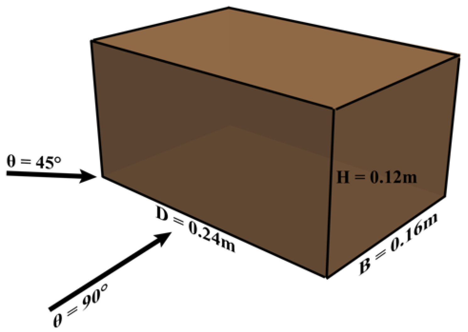
To analyze the effects of the generated turbulent inflow on aerodynamic characteristics of low-rise buildings, in the present study, we focus on an isolated low-rise building with a flat roof without eaves, and the building geometry is characterized by a height (
) equal to 0.12 m, a breadth (
B) equal to 0.16 m, and a depth (
D) equal to 0.24 m, which is the same with the dimensions in the wind tunnel test. The low-rise building is impacted by the generated turbulence fields for two wind directions:
θ = 90° and
θ = 45°, which is illustrated in
Figure 1. The case of
θ = 90° represents the condition that the largest building surface area is directly impacted by the inflow, while the
θ = 45° represents the condition that the incoming flow is evenly separated by the building at the edges of the windward side, which leads to a complex flow field around the building. Since the similar angle combination of 45° and 90° is also adopted by other references [
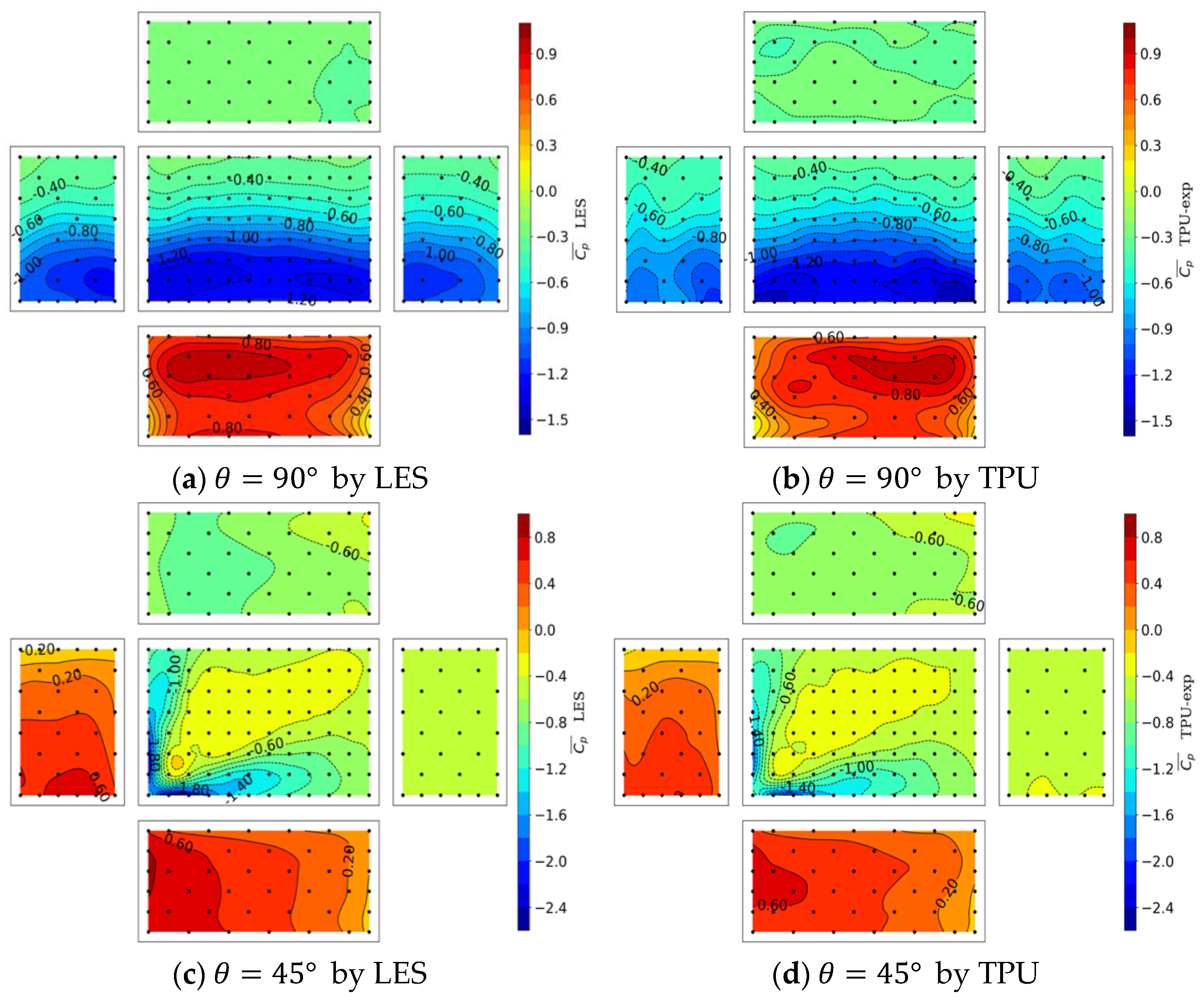
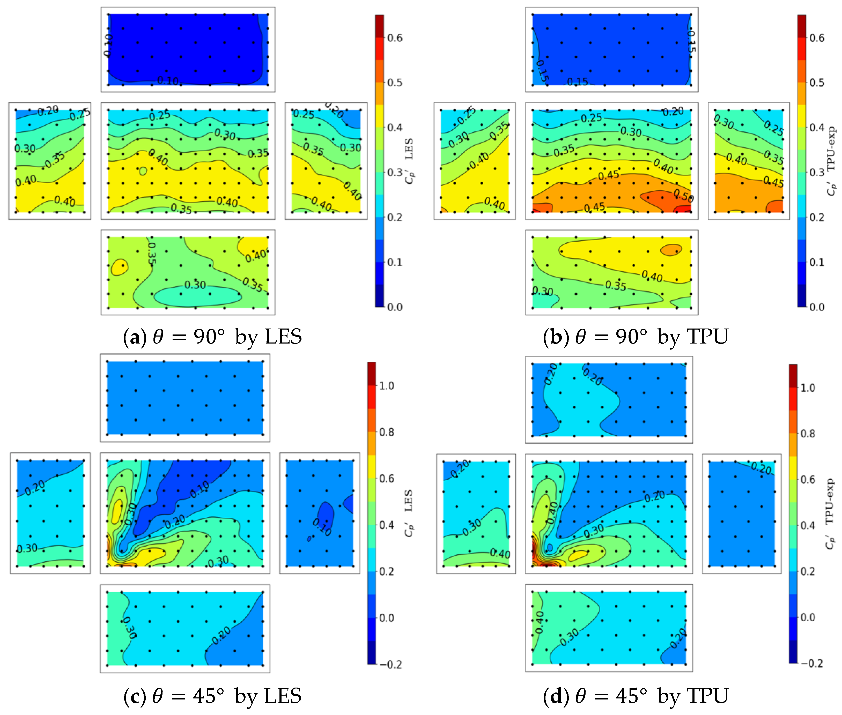
9], we believe such two cases can be adopted as the typical condition for evaluating the generated turbulence wind field. The fluctuating surface pressure coefficient on buildings will be compared with the corresponding wind tunnel results to evaluate the rationality of the generated wind field. In the wind tunnel test, the wind pressure measurement taps are disposed uniformly over the surfaces of the tested models with spaces of about 0.02 m to measure the wind-induced building surface pressure. There are 240 taps for the isolated model, and all taps can measure the fluctuating wind pressures nearly synchronously at a sampling frequency of 500 Hz for a duration of 18 s. For the corresponding simulation cases, hundreds of uniformly distributed probe points, which follow the same distribution as the wind tunnel test, are prescribed on the building surface to acquire pressure data at each timestep for the duration of 10 s. The distribution of pressure measurement points on the building surfaces is illustrated by the black dots in Figures 12 and 13.
2.2. Domain Setups and Grid Mesh
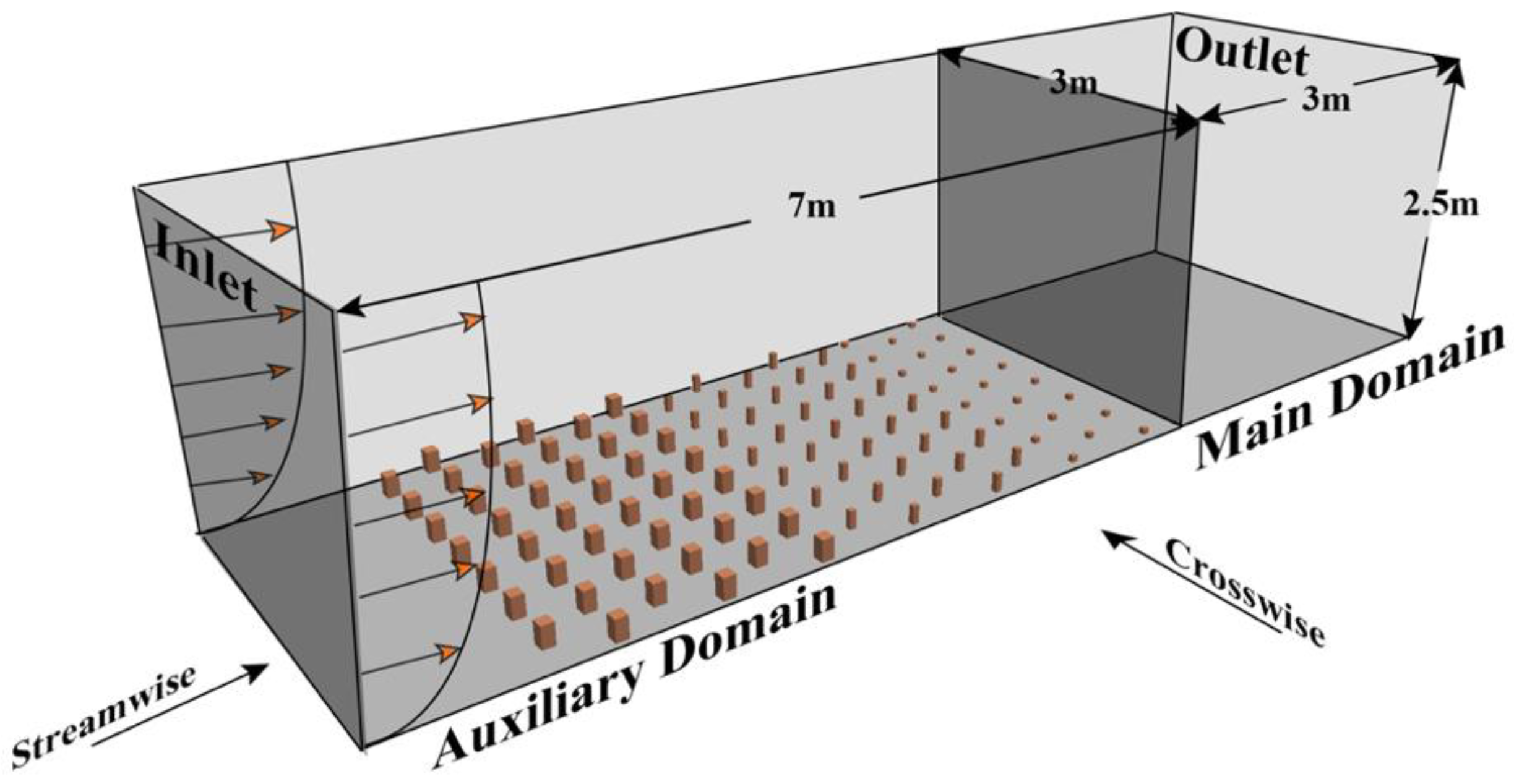
All the numerical simulations are conducted in the rectangle domains; the crosswise width of the domain is 3 m, and the height is 2.5 m. The streamwise length of the domain is 10 m and divided into two parts: the auxiliary domain for the first 7 m and the main domain for the last 3 m; see
Figure 2.
For the boundary conditions, the symmetry condition is imposed at the top and two lateral surfaces, the bottom and the buildings’ surfaces are forced to be zero velocity and zero-gradient pressure, while the advective outflow condition is set to the outlet patch to avoid the possible reflection of eddies at the outlet. The uniform inflow velocity condition with a specific vertical profile is prescribed at the inlet patch, and the inflow laminar will be disturbed into turbulence after passing through the auxiliary domain.
The automatic grid generation method named snappyHexMesh is adopted to generate the grid system for the whole domain. This method is provided by OpenFOAM and has been applied in several numerical studies to gain a high-quality mesh [
18]. The reason for using this method is as follows: (1) the structured meshes with high orthogonality can be generated quickly for the domain with any geometry placed inside, and (2) the mesh density in the different areas can be flexibly prescribed so that a mesh system with low total grid number and high grid resolution in the vicinity of the building can be obtained. The mesh quality of this method has been checked, but not reported here, by using such a grid system to simulate the aerodynamic characteristics of flow passing a cylinder. For the LES simulation with a high Reynold number, fine near-wall grid spacing should be used for better results. In the present simulation, the mesh in the near ground area and the near building area is densified, and an extremely small scale is used as the height of the first grid layer on the target building surface to make the mean dimensionless wall distance
smaller than 2. The total grid numbers for the empty domain without a building and the domain with a building are 1.4 million and 4.18 million, respectively. The auto-generated mesh system of the isolated building for a 45-degree angle is shown in
Figure 3.
2.3. Numerical Schemes
In the present study, the LES model is adopted to consider the effect of turbulence characteristics for the flow field and the wind pressure on a building surface. The standard Smagorinsky–Lilly turbulence model is adopted as the sub-grid model with the Smagorinsky Coefficient , and the Cube filtering method is used here. To improve the simulation results of turbulence near the wall, the Van Direst wall function is used to modify the standard Smagorinsky model.
All simulations are realized based on the open-source Finite Volume toolbox OpenFOAM. The velocity-pressure coupled equations of the incompressible flow are solved by the widely used pressure implicit with splitting of operators (PISO) method, and the numerical errors due to non-orthogonality of the mesh system are corrected once at each timestep. The time derivative is discretized using the second order, fully implicit backward differences scheme, while the adopted timestep leads to a maximum Courant number in all simulations lower than 1.0 to ensure numerical stability. The overall second-order differentiation scheme is adopted for the spatial discretization, and the diffusion term is discretized by the LUST scheme, which consists of 75% linear and 25% linear-upwind scheme and offers a good trade-off between low dissipative behavior and numerical stability; the convective terms and the gradient term are discretized by the Gauss linear scheme.
3. Inflow Turbulence Generation
To accurately simulate the aerodynamics characteristics of buildings and structures immersed in the ABL, a turbulent inlet is often required by the large eddy simulation models [
19]. In the present paper, an efficient method is proposed to generate the turbulence field in the target area of the domain. In this method, we modeled the staggered roughness blocks in the simulation domain similar to the method used in wind tunnel tests, and a turbulent wind field can be produced in the downstream area. To improve computational efficiency, the implementation of roughness blocks is realized by adding an appropriate source term in the momentum equation [
12]:
where
is the average velocity over the fluid volume,
is the average velocity over the whole grid,
is the volume occupancy rate that is the ratio of obstacle volume to the whole grid volume
,
is the drag coefficient of any bluff body, and
is the frontal area of the single bluff body. In case of the realization of roughness blocks, we first generate a mesh and select the grid cells occupied by roughness blocks; then, the drag force given by the equation will be applied in these selected cells to represent the effects of the solid blocks. Since the velocity in these cells should be constantly zero, we set the volume occupancy rate
to a number smaller than but very close to 1.0. As a result, the
is a number approaching infinity, and the grid-averaged velocity in selected cells will be nearly zero [
13].
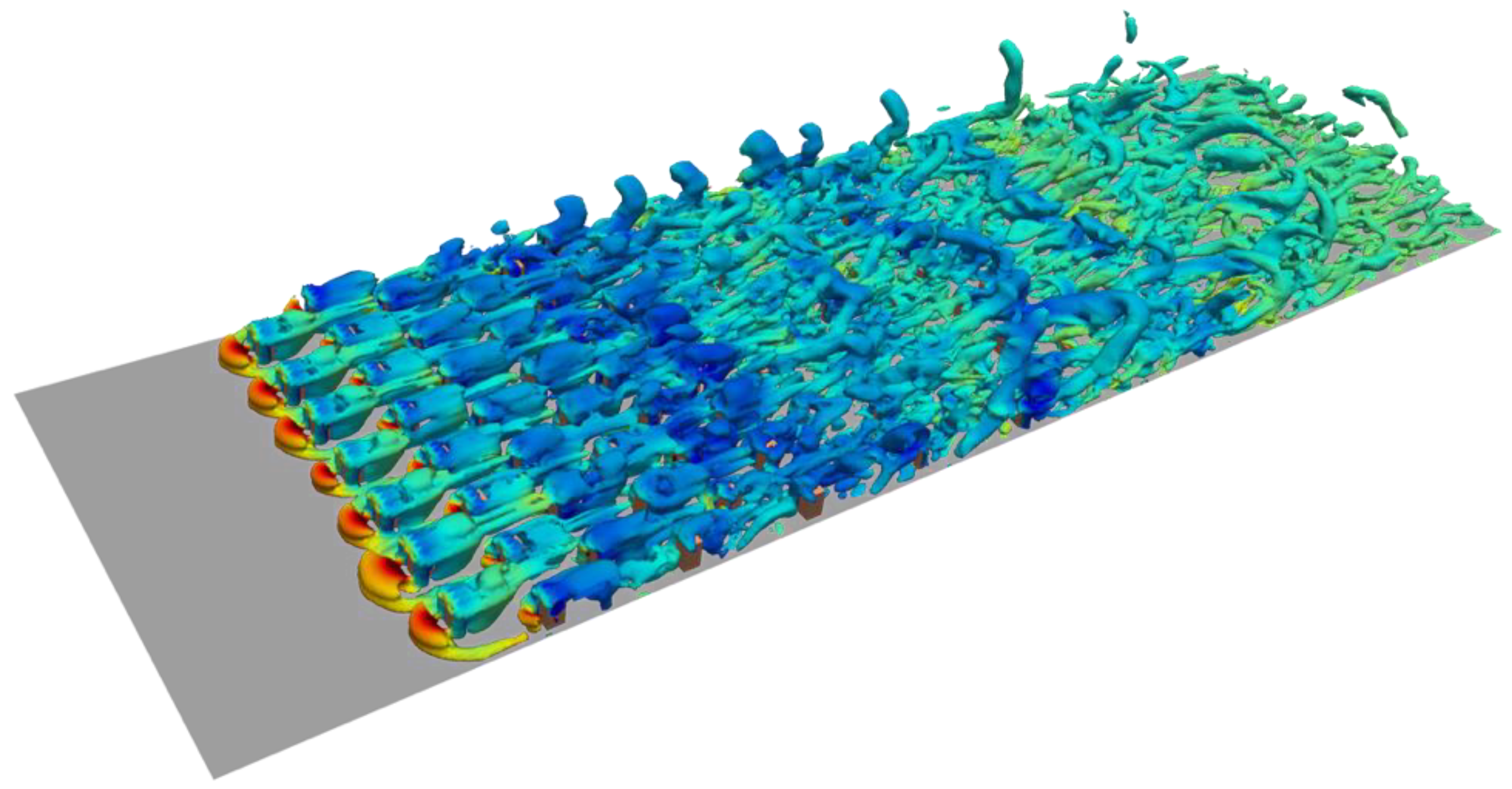
The modeled roughness blocks are placed in the first 6.5 m of the domain, and the distribution of blocks is shown in
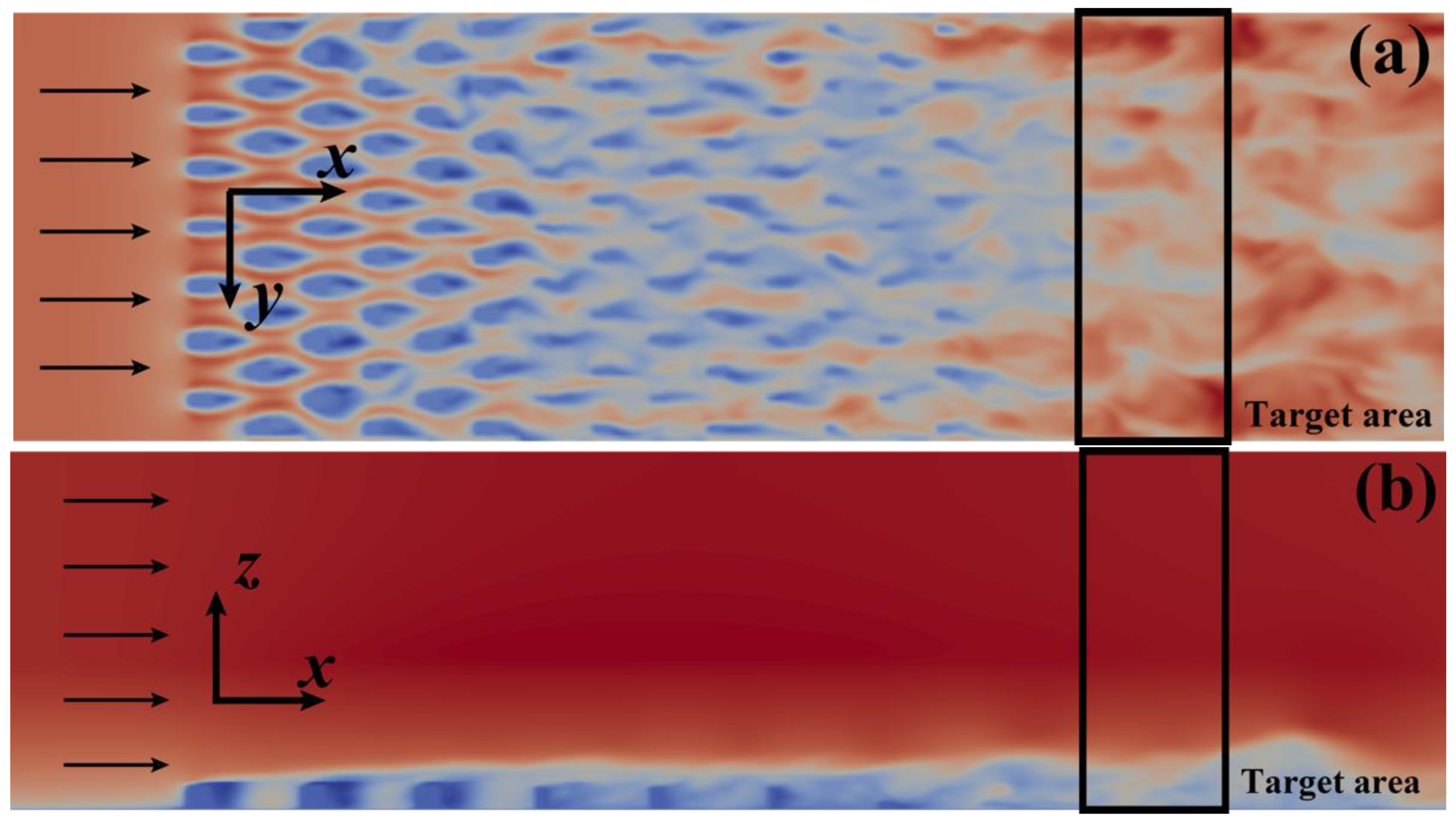
Figure 1. After passing through the virtual roughness blocks, a fully developed turbulent field is generated in the downstream area. The streamwise velocity in the near ground area at height = 0.05 m and in the crosswise central plane are shown in
Figure 4. A fully developed turbulence field can be generated in the downstream place. It should be noted that the wind flow in the higher area is prescribed to keep undisturbed to avoid the influence of the symmetry boundary condition at the top plane on the velocity field.
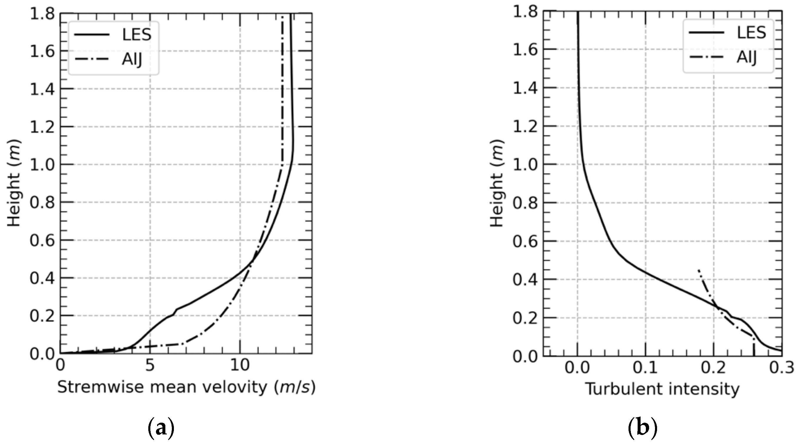
Figure 5 reports the streamwise mean velocity profile and the turbulence intensity profiles within the target area range from 7 m away from the inlet patch to 8 m, and the AIJ profiles are plotted as the reference. As shown in
Figure 5, the turbulence intensity in the near ground meets our requirement, but an obvious deviation between result and requirement exists in the mean velocity profile. As discussed in the previous section, the biggest disadvantage of the precursor method is that it is hard to control the statistical characteristic of the generated turbulent field. Since the ground roughness is dependent on the roughness blocks, both the mean velocity profiles and the mean turbulent intensity profiles can only be reproduced by repeated adjustment of block distribution. Although there are many studies to figure out the relationship between the distribution of roughness blocks and corresponding turbulent fields [
20], using roughness blocks to generate turbulent fields is still time-consuming work.
To minimize the efforts of adjusting blocks distributions, a more efficient method is adopted in the present paper to generate a turbulent field with required mean velocity and turbulent intensity profiles. In the first step of the generation process, a uniform inflow following the required mean velocity profile is added to the simulation domain, and several distributions of roughness blocks are adopted, respectively, to try to generate a turbulent field with the required turbulent intensity in a target area. Since the mean velocity profile in the target area is not the main focus of attention in this step, this trial-and-error work to modify the block distributions will not take so long; in the second step, a recycling and reshaping method (RRM) is used to modify the velocity profile in the target area, by which the inflow velocity profile is reshaped every few seconds based on the mean velocity profile in the target area as follows:
where
is the required mean velocity profile in the target area,
is the time averaged velocity profile in the target area during the
th correction,
is the mean velocity profile in the inlet patch during the
th correction,
is the transverse average of values,
is a parameter used to ensure the
th velocity modification at inflow patch is zero-sum, and
is the corresponding grid scale in the vertical direction. For example, during one recycling and reshaping procedure, if the mean velocity in the near ground area is found to be lower than the target values, in the next timestep the inflow velocity in the lower area will be increased to lead to higher near-ground velocity in the target area, while the inflow velocity in the higher area will be decreased to ensure the same flux at the inlet patch. Finally, after several times of recycling and reshaping, the mean velocity profile in the target area will meet the requirement. Regarding the turbulence intensity profile, since the modification of the inflow velocity is not big, the turbulent intensities in the target area should not show a big difference after the modification.
The above RRM method is obtained to generate a turbulent field within the target area, which ranges from 7 m away from the inlet patch to 8 m. There is still 2 m distance before the disturbed velocity reaches the outflow patch to avoid boundary condition effects on the solution. The streamwise mean velocity on the crosswise plane after the recycling and reshaping modification is illustrated in
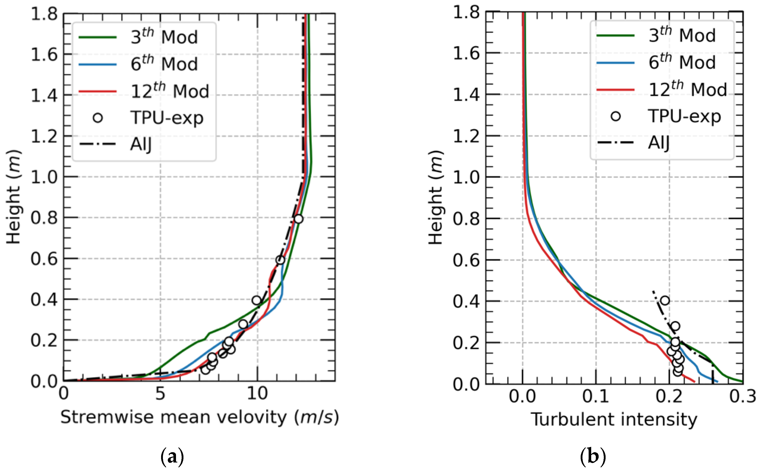
Figure 6, and the streamwise wind velocity profiles and turbulence intensity profiles of the simulated wind field during the modification process are shown in
Figure 7. The statistical characteristics of the turbulence field used for the wind tunnel experiment are illustrated together in
Figure 7 for comparison, and the recommendation profiles of the AIJ standard are provided as a reference. The results show that the RRM is suitable to reshape and improve the velocity profiles in the target area in the terms that the mean streamwise velocity profile gradually meet our requirement. The final turbulence field generated by RRM with roughness blocks is in good agreement with the velocity conditions measured from the wind tunnel experiment. However, focusing on the lower part of the test domain, in which the low-rise building models are immersed, there are still some deviations between the experimental and numerical profiles. The mean streamwise velocity is slightly overestimated by RRM, which leads to different reference velocities for two turbulence fields:
= 7.8 m/s for wind tunnel and
= 7.7 m/s for RRM. Regarding the fluctuation of velocity in the near ground area, although the turbulence intensity keeps decreasing during the modification, which is more likely to be caused by the increase of mean wind speed, the turbulence intensity remains at a high value and finally reaches a perfect agreement with the measured experimental result. Since the low-rise buildings in the present paper are all within an area below 0.2 m, this generated turbulent field is suitable for the present study.
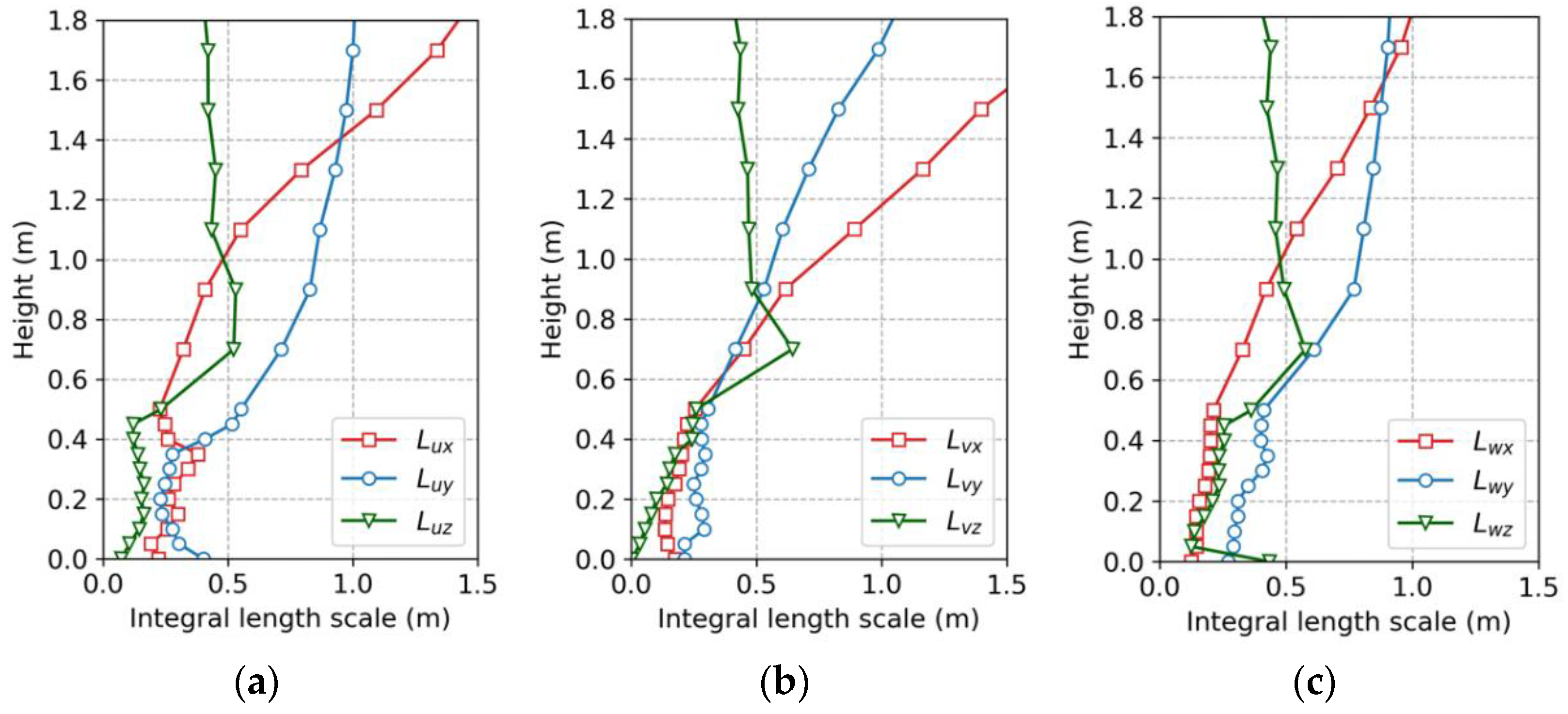
The special correlation of the turbulence field can be represented in terms of the integral length scales. During the generation of the velocity field, the time-varying velocity at different locations within the target area is acquired at each timestep, and the integral length scales at different heights can be calculated based on the velocity series.
Figure 8 reports the integral length scales of orthogonal velocity components in three directions. As shown in the diagrams, the three-dimensional special correlations of the turbulence field are well generated by RRM, which indicates the complex topology of vorticities within the turbulence field. Aiming at illustrating the effects of modeled roughness blocks on the generation of the turbulence field, the iso-surface of the instantaneous vorticity is shown in
Figure 9.
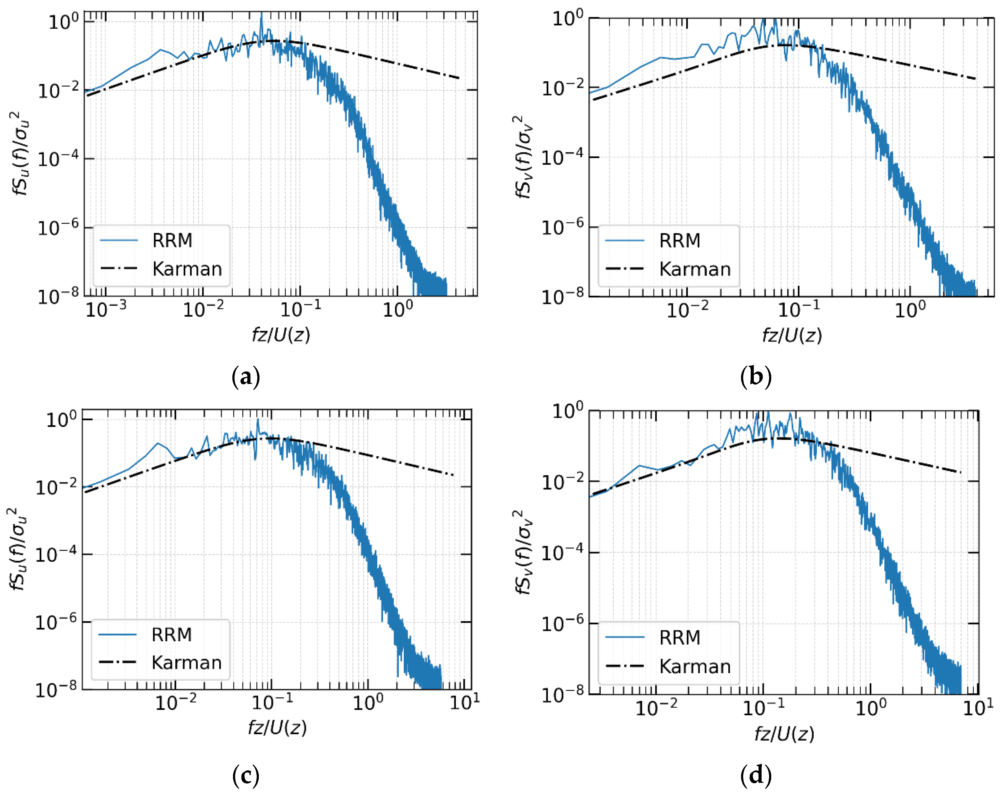
The power spectrum of fluctuating wind velocity components, which represents the motion of eddies with different sizes, is also analyzed to clarify the influence of inflow generation methods on the simulated turbulence field in the CFD model. Since LES can resolve the eddies, a time-varying wind velocity satisfying the von Karman spectral model can lead to accurate predictions of wind effects on buildings and structures.
Figure 10 shows the normalized power spectral densities (PSD) calculated from the time histories of the streamwise and crosswise fluctuating wind speed components at two different heights. As a reference, the Karman power spectrum, which is widely adopted to express the power spectrum of natural wind flow in the wind engineering field, is shown in
Figure 10 to evaluate the performance of turbulence generation methods. Both the two groups of the power spectrum results are in good agreement with the Karman power spectrum in the low-frequency range, but they decay rapidly and deviate significantly from the Karman type power spectrum in the higher-frequency range. This is due to the grid restrictions in capturing small-scale turbulence components, which should be improved by densifying the grid system.
In general, compared with the physically developed turbulence field, the numerical turbulence field by RRM shows the same second-order statistical characteristic as the target velocity field. However, whether it can be used as a turbulent inflow for simulation of fluctuating surface pressure on bluff bodies needs further verification.
4. Validation of Generated Inflow Turbulence
In this section, the LES results of the building impacted by turbulence fields are reported and compared with the experimental results in the wind tunnel. The characteristics of the turbulence field around buildings are firstly presented in terms of the iso-surface of instantaneous vorticity, then the pressure data are presented through statistical results including the distribution of mean pressure coefficient and the distribution of standard deviation of pressure coefficient.
The isolated building is impacted by the turbulence field for two angles of attack,
θ = 90° and
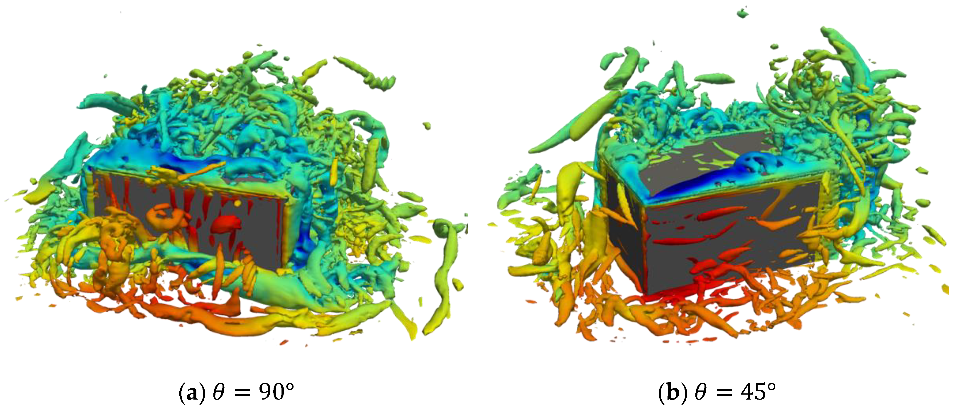
θ = 45°, respectively. The instantaneous velocity field for the last timestep is recorded to analyze the turbulence characteristics around buildings. The topology of vorticities around the isolated building for the two attack angles is shown in
Figure 11, and the vorticity is identified by the Q criteria. As we can see, for the attack angles equal to 90°, the flow is evenly separated at the edges of the windward side; for the attack angles equal to 45°, the flow is firstly divided into two parts by the front edge, then the two flows develop downstream along the top edges of the two side surfaces, and finally form the spiral flows.
Focusing on the distribution of surface wind pressure, during each simulation, about 100,000 timesteps of pressure data on the building surface are saved. To avoid the error caused by the insufficient development of the flow field, the building surface pressure for the first 30,000 timesteps is disregarded in the post-processing of the data. The time-averaged surface pressure coefficient on buildings for attack angles equal to 90° and 45° is shown in
Figure 12. The corresponding wind tunnel results are shown together as a reference. The numerical pressure results for the attack angles equal to 90° and 45° are in very good agreement with the wind tunnel results. Both the maximum pressure coefficient on the windward side and the minimum pressure coefficient at two separate corners can be well reproduced by LES using the turbulence field generated by RRM.
Figure 12.
The time-average surface pressure coefficient on an isolated low-rise building by LES (left side) and by TPU (right side).
Figure 12.
The time-average surface pressure coefficient on an isolated low-rise building by LES (left side) and by TPU (right side).
The standard derivation of the surface pressure coefficient on the building for attack angles equal to 90° and 45° is shown in
Figure 13, together with the corresponding wind tunnel results. The numerical and experimental results show good consistency for most building surface area, except for the flow separation corners, in which the fluctuation of simulated surface pressure coefficient is insufficient compared with that of the measured results. This underestimate of the computed values near the windward edge is widely reported when using LES for the analysis of wind fields around bluff bodies [
9,
15,
21]. This phenomenon is not clearly explained, but it may be caused by the following several reasons: the numerical damping of insufficient discrete order applied in the vicinity of the building, the grid resolution is not fine enough to capture the strong shear coupled with widely varying instantaneous flow directions near the leading edge, or the adopted turbulence model is inappropriate. Further analysis should be carried out to make a clear explanation.
Figure 13.
The fluctuation of surface pressure coefficient on an isolated low-rise building by LES (left side) by TPU (right side).
Figure 13.
The fluctuation of surface pressure coefficient on an isolated low-rise building by LES (left side) by TPU (right side).
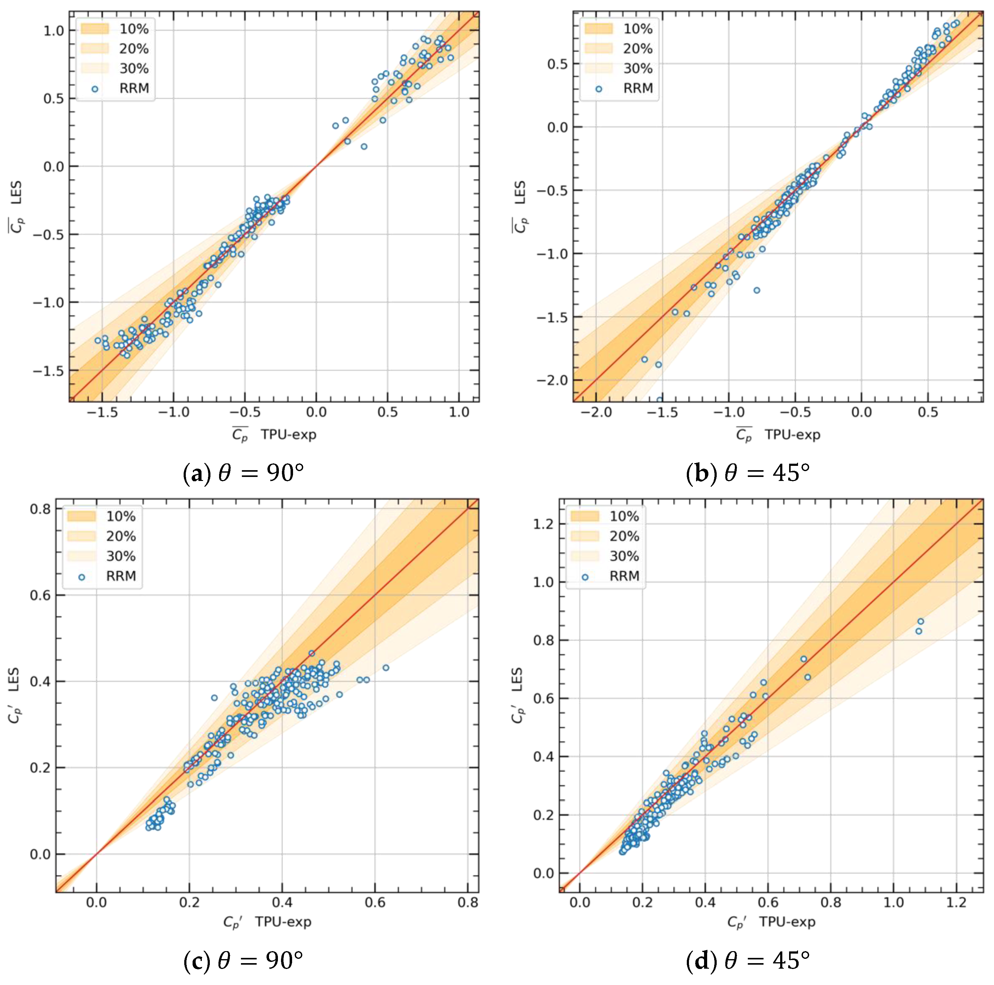
To make a clearer evaluation of the obtained numerical results, the experimental measurements and numerical data for each pressure probe are plotted in a correlation diagram.
Figure 14a,b shows the correlation of the time-average surface pressure coefficient for attack angles equal to 90° and 45°, respectively, while
Figure 14c,d shows the fluctuation results of surface pressure coefficient, and the distribution of correlated points is quantified in
Table 1. For all four groups of data, the correlated points are generally located along the diagonal. Regarding the time-average pressure results, for two attack angles, nearly 90% of correlated points are located in the tolerance range of 30%, which represents a high accuracy of the LES simulation. For the fluctuating pressure result, the larger deviation between experiment and simulation is once again proven by the correlation analysis, in which the percentage of points in the 30% tolerance range is equal to 85.8% and 76.7%, respectively. However, although there are some differences between the two results, the general characteristics of the wind-induced surface pressure obtained by LES can be considered in good accordance with the wind tunnel results over the whole building surface. Such results indicate that the numerical turbulence field generated by RRM is capable of the analysis of aerodynamic characteristics on buildings.
