Application of Miniaturized Sensors to Unmanned Aerial Systems, A New Pathway for the Survey of Polluted Areas: Preliminary Results

 , , , and
Abstract
1. Introduction
2. Materials and Methods
2.1. Lidar
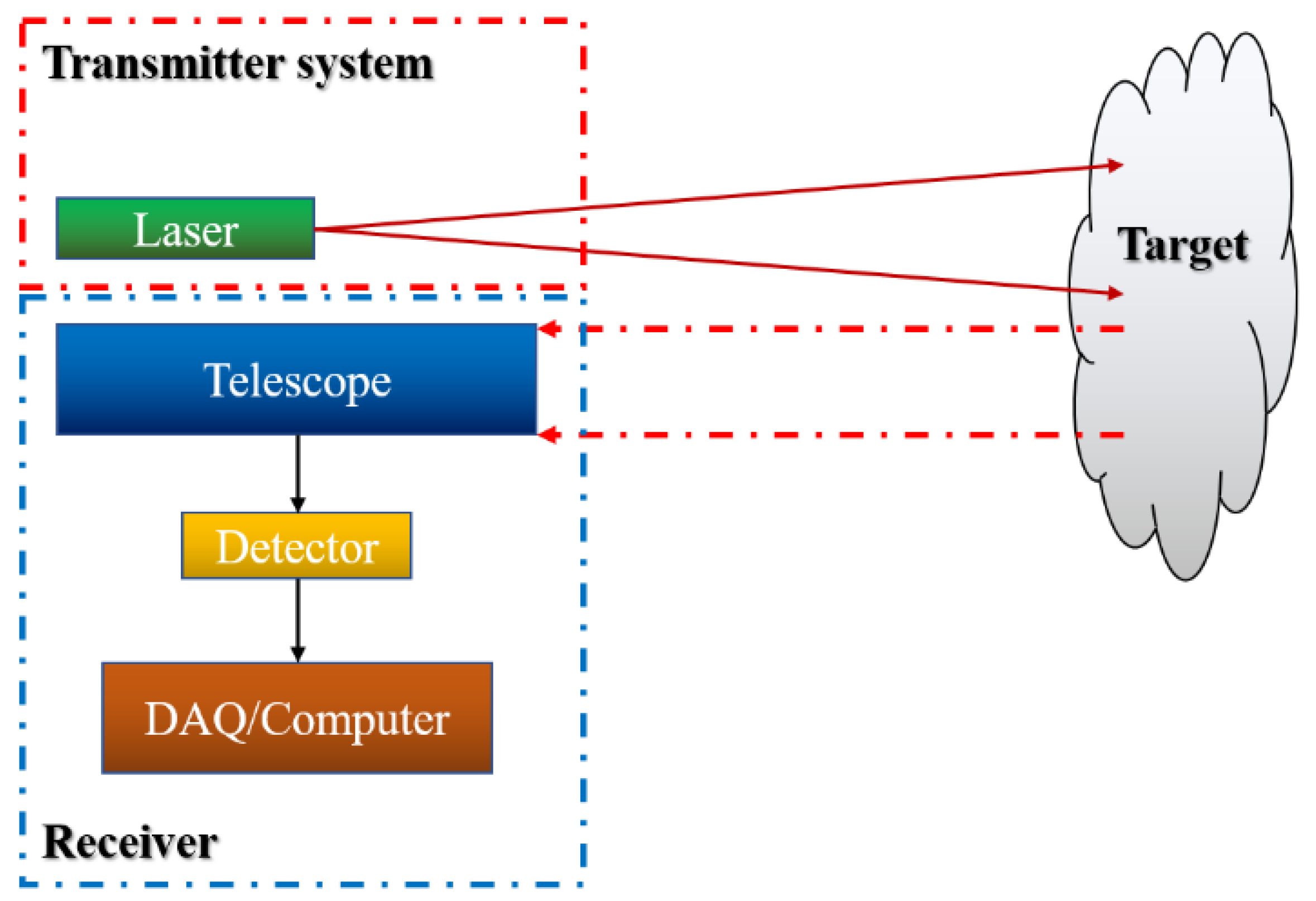
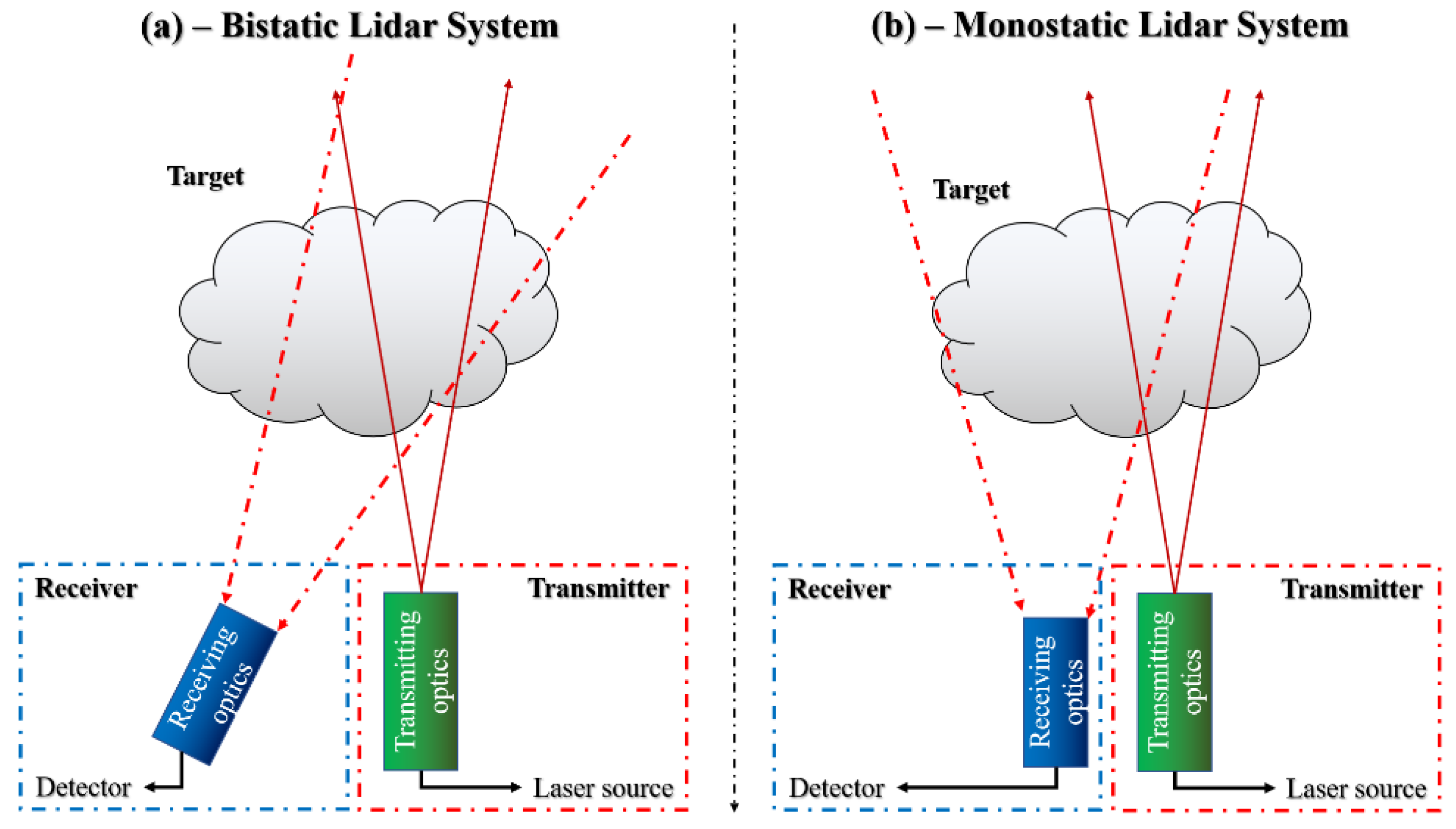
2.1.1. Lidar Standoff Systems for Environmental Monitoring
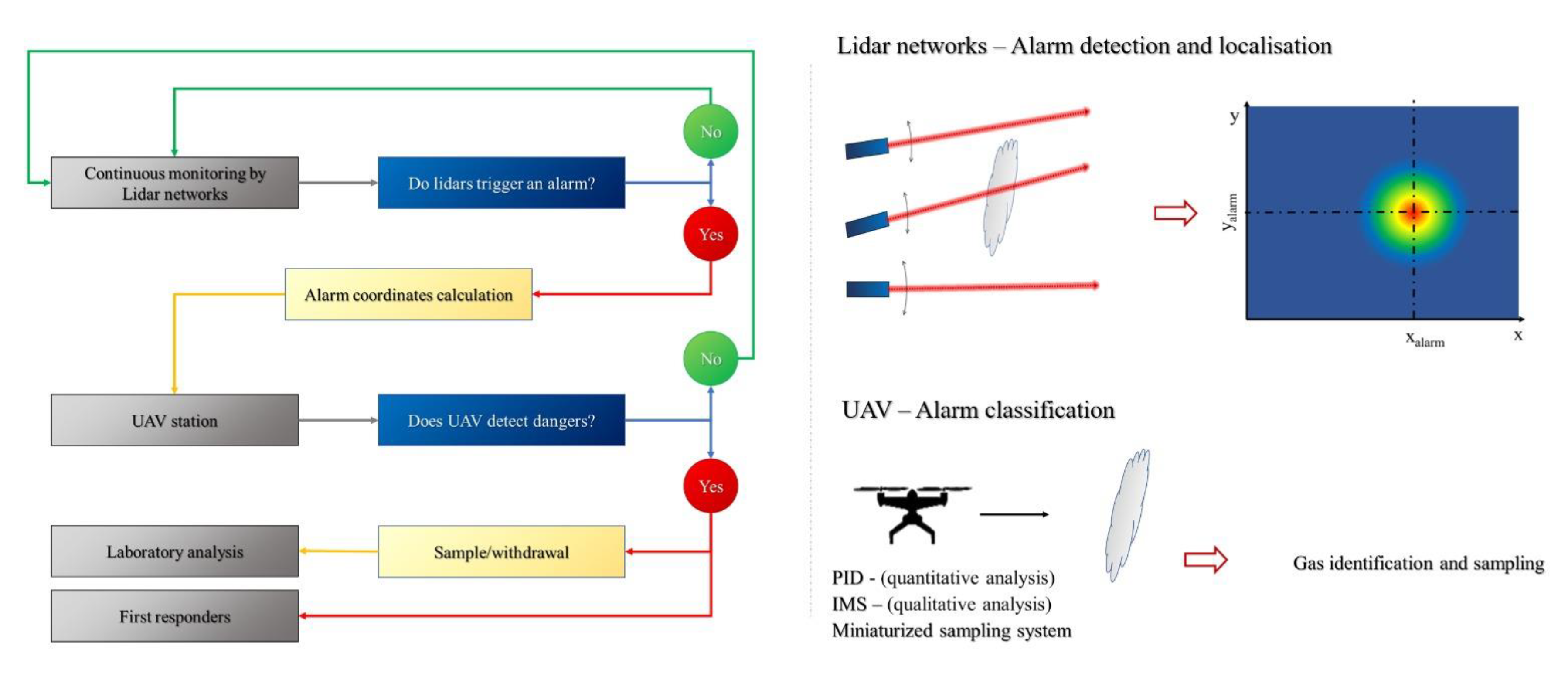
2.1.2. Lidar Network as a Method for Environmental Pollution Detection
2.2. UAV
2.2.1. UAV with Integrated Payload
2.2.2. UAV with Integrated Sensors as a Method for Pollutants Identification
2.2.3. Miniaturized Sensors and Sampling Devices for Chemical Identification
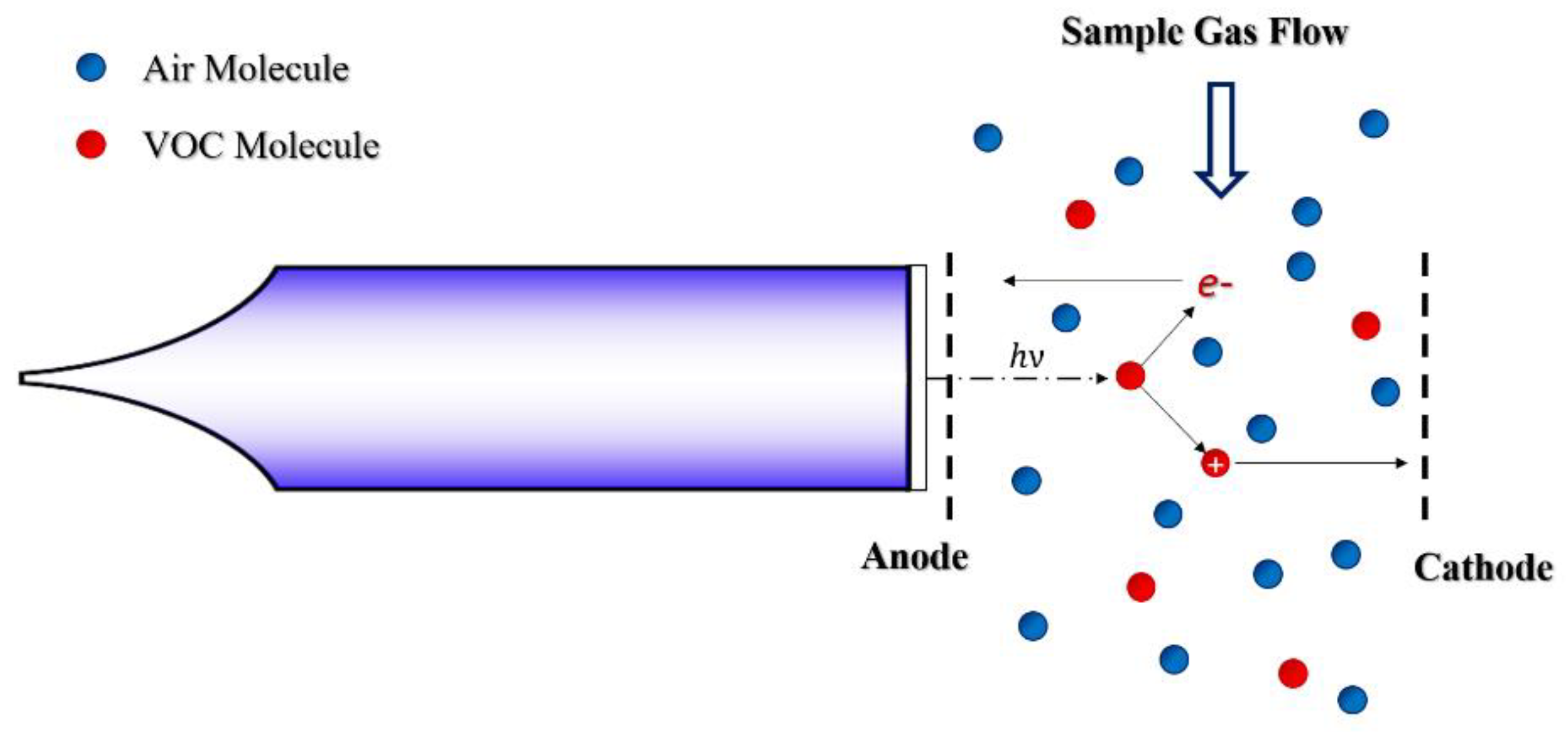
Photo-Ionization Detectors (PID)
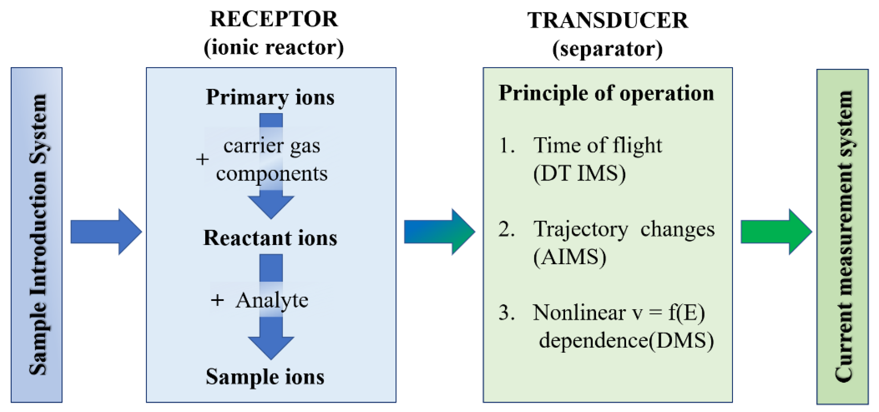
Ion-Mobility Spectrometry (IMS)
Miniaturized Sampling Systems for UAV Application
3. Preliminary Results
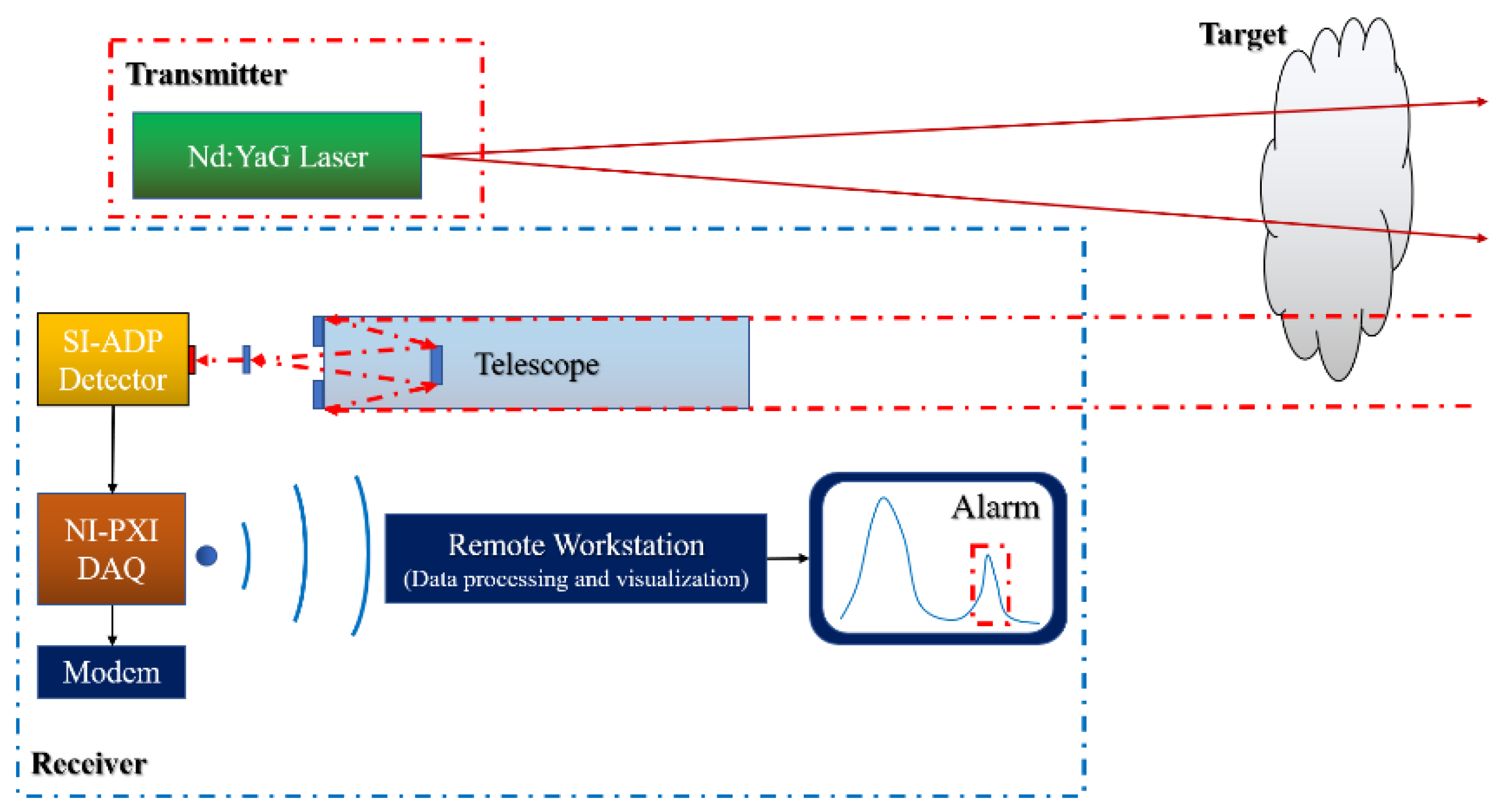
3.1. Lidar Test Campaign
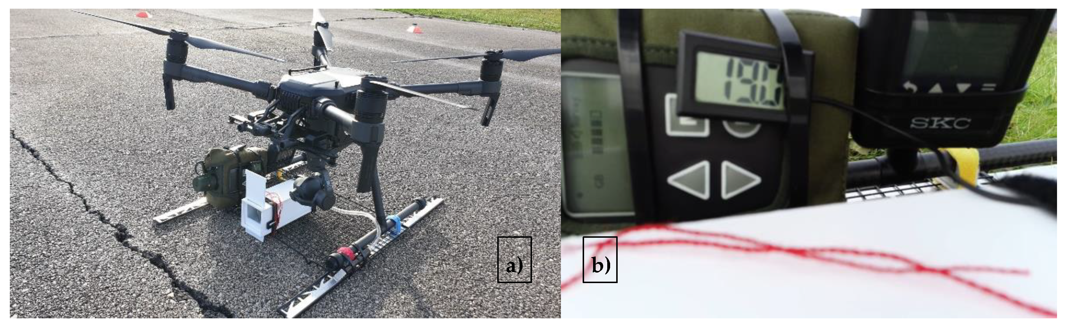
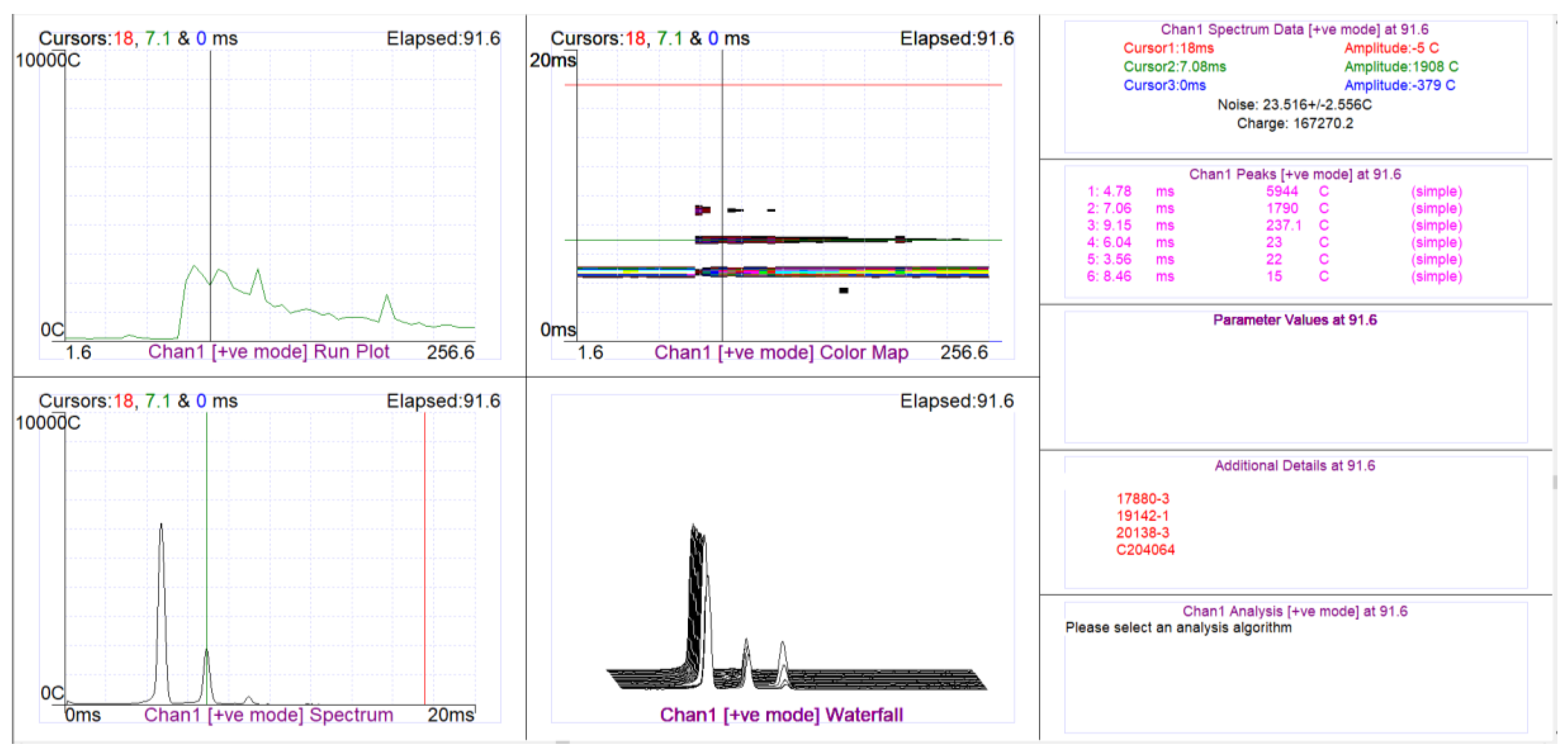
3.2. Multisensor Drone Test Campaign
4. Conclusions and Future Developments
Author Contributions
Funding
Acknowledgments
Conflicts of Interest
References
- Goyal, A.K.; Myers, T.R. Active Mid-Infrared Reflectometry and Hyper Spectral Imaging. Laser-Based Optical Detection of Explosives; CRC Press: Boca Raton, FL, USA, 2015; pp. 168–212. [Google Scholar]
- Sasic, S.; Ozaki, Y. Raman, Infrared, and Near-Infrared Chemical Imaging; Wiley: New York, NY, USA, 2010. [Google Scholar]
- Parracino, S.; Richetta, M.; Gelfusa, M.; Malizia, A.; Bellecci, C.; De Leo, L.; Perrimezzi, C.; Fin, A.; Forin, M.; Giappicucci, F.; et al. Real-time vehicle emissions monitoring using a compact LiDAR system and conventional instruments: First results of an experimental campaign in a suburban area in southern Italy. Opt. Eng. 2016, 55, 103107. [Google Scholar] [CrossRef]
- Gaudio, P. UMEL: A new regression tool to identify measurement peaks in Lidar/Dial system for environmental physics applications. Rev. Sci. Instrum. 2014, 85, 063112. [Google Scholar]
- Gaudio, P. Application of a CO2 dial system for infrared detection of forest fire and reduction of false alarm. Appl. Phys. B 2007, 87, 373–378. [Google Scholar]
- Rossi, R.; Ciparisse, J.; Malizia, A.; Gelfusa, M.; Gaudio, P. Multiwavelengh differential absorption lidar to improve measurements accuracy: Test with ammonia over a traffic area. Appl. Phys. B 2018, 148, 124–148. [Google Scholar]
- Rosser, K.; Pavey, K.; FitzGerald, N.; Fatiaki, A.; Neumann, D.; Carr, D.; Hanlon, B.; Chahl, J. Autonomous Chemical Vapour Detection by Micro UAV. Remote Sens. 2015, 7, 16865–16882. [Google Scholar] [CrossRef]
- Gas-Drone: Portable Gas Sensing System on UAVs for Gas Leakage Localization. Available online: http://3dom.fbk.eu/sites/3dom.fbk.eu/files/pdf/Rossi_etal_IEEE-gas_sensors_uav.pdf (accessed on 16 March 2020).
- Karpowicz, J. Detecting Radiological, Biological and Chemical Threats with Drones. Available online: https://www.commercialuavnews.com/public-safety/detecting-radiological-biological-chemical-threats-drones (accessed on 16 March 2020).
- Nikolic, J.; Burri, M.; Rehder, J.; Leutenegger, S.; Huerzeler, C.; Siegwart, R. A UAV system for inspection of industrial facilities. IEEE Aerosp. Conf. 2013, 5. [Google Scholar] [CrossRef]
- Bolla, G.; Casagrande, M.; Dal Moro, R.; Destro, M. ARIA: Air Pollutants Monitoring Using UAVs. Metro. Aero. Space 2018, 6. [Google Scholar] [CrossRef]
- Bezantakos, S.; Schmidt-Ott, F.; Biskos, B. Performance evaluation of the cost-effective and lightweight Alphasense optical particle counter for use onboard unmanned aerial vehicles. Aero. Sci. Tech. 2018, 52, 385–392. [Google Scholar] [CrossRef]
- Gu, Q.; Michanowicz, D.; Jia, C. Developing a Modular Unmanned Aerial Vehicle (UAV) Platform for Air Pollution Profiling. Sensors 2018, 18, 4363. [Google Scholar] [CrossRef]
- Marinelli, W.; Schmit, T.; Dupuis, J.; Mulhall, P.; Croteau, P.; Manegold, D.; Beshay, M.; Lav, M. Cooperative use of standoff and UAV sensors for CBRNE detection. Proc. SPIE 2015, 5. [Google Scholar] [CrossRef]
- Weitkamp, C. Lidar Range-Resolved Optical Remote Sensing of the Atmosphere; Springer: Berlin, Germany, 2005. [Google Scholar]
- Kovalev, V.; Eichenger, W. Elastic Lidar: Theory, Practice and Analysis Methods; Wiley: New York, NY, USA, 2004. [Google Scholar]
- Martellini, M.; Malizia, A. Cyber and Chemical, Biological, Radiological, Nuclear, Explosives Challenges, Cham; Springer: Berlin, Germany, 2017. [Google Scholar]
- Measures, R. Laser Remote Sensing―Fundamentals and Applications; Wiley: New York, NY, USA, 1985. [Google Scholar]
- Fiocco, G.; Smullin, L. Detection of Scattering Layers in the Upper Atmosphere (60–140 km) by Optical Radar. Nature 1963, 199, 1275–1276. [Google Scholar] [CrossRef]
- Del Guasta, M. Daily Cycles in Urban Aerosol Observed in Florence by Means of an Automatic 532–1064 nm LIDAR. Atmos. Environ. 2002, 36, 2853–2865. [Google Scholar] [CrossRef]
- Likar, K.; Eichinger, V. Monitoring of the Particles Above the Unpaved Road by Lidar Technique. Glob. Nest J. 2011, 13, 309–316. [Google Scholar]
- He, T.; Stanič, S.; Gao, F.; Bergant, K.; Veberič, D.; Song, X.; Dolžan, A. Tracking of Urban Aerosols Using Combined LIDAR-Based Remote Sensing and Ground-Based Measurements. Atmos. Meas. Tech. 2012, 5, 891–900. [Google Scholar] [CrossRef]
- Mei, L.; Brydegaard, M. Atmospheric Aerosol Monitoring by an Elastic Scheimpflug Lidar System. Opt. Exp. 2015, 23, A1613–A1628. [Google Scholar] [CrossRef]
- Bösenberg, J. EARLINET: A European Aerosol Research Lidar Network. In Proceedings of the 20th International Laser Radar Conference (IPSL), Vichy, France, 10–14 July 2000; Available online: https://www.mpimet.mpg.de/fileadmin/publikationen/Reports/max_scirep_348.pdf (accessed on 5 May 2020).
- Andreucci, F.; Arbolino, M.; Sozzi, R. Lidar Utilisation for Industrial Stack Plume Automatic Tracking. II Nuovo Cim. C 1991, 14, 453–462. [Google Scholar] [CrossRef]
- Quantum Electronics and Plasma Physics Research Group. Available online: www.qepresearch.it (accessed on 16 March 2020).
- Feron, E.; Johnson, E.N. Aerial Robotics; Springer: Berlin, Germany, 2008. [Google Scholar]
- International Conference on Modelling and Simulation for Autonomous Systems. Available online: https://link.springer.com/conference/mesas (accessed on 16 March 2020).
- Nonami, K. Autonomous Flying Robots: Unmanned Aerial Vehicles and Micro Aerial Vehicles; Springer: Berlin, Germany, 2010. [Google Scholar]
- Beard, R.; McLain, T. Small Unmanned Aircraft: Theory and Practice; Princeton Univ. Press: Princeton, NJ, USA, 2012. [Google Scholar]
- Siegwart, R.; Nourbakhsh, I.R.; Scaramuzza, D. Introduction to Autonomous Mobile Robots; MIT Press: Cambridge, MA, USA, 2011. [Google Scholar]
- Siciliano, B.; Sciavicco, L.; Villani, L.; Oriolo, G. Robotics: Modelling, Planning and Control; Springer: Berlin, Germany, 2009; pp. 469–521. [Google Scholar]
- Gurdan, D.; Stumpf, J.; Achtelik, M.; Doth, K.-M.; Hirzinger, G.; Rus, D. Energy-efficient autonomous four-rotor flying robot controlled at 1 khz. IEEE Int. Conf. Robot. Auton. Syst. 2007, 4. [Google Scholar] [CrossRef]
- Hoffmann, G.; Huang, H.; Waslander, S.L.; Tomlin, C. Quadrotor helicopter flight dynamics and control: Theory and experiment. AIAA Guid. Navig. Control Conf. 2007, 6. [Google Scholar] [CrossRef]
- Tomic, T.; Schmid, K.; Lutz, P.; Domel, A.; Kassecker, M.; Mair, E.; Grixa, I.; Ruess, F.; Suppa, M.; Burschka, D. Toward a fully autonomous UAV: Research platform for indoor and outdoor urban search and rescue. IEEE Robot. Autom. Mag. 2012, 3, 46–56. [Google Scholar] [CrossRef]
- Fahlstrom, P.; Gleason, T. Introduction to UAV Systems; John Wiley & Sons: New York, NY, USA, 2012. [Google Scholar]
- Naldi, R.; Forte, F.; Marconi, L. A Class of Modular Aerial Robots. IEEE Conf. Decis. Control Eur. Control Conf. 2011, 12. [Google Scholar] [CrossRef][Green Version]
- Mettler, B. Identification, Modeling and Characteristics of Miniature Rotorcraft; Springer: Berlin, Germany, 2002. [Google Scholar]
- Achtelik, M.C.; Doth, K.M.; Gurdan, D.; Stumpf, J. Design of a multi rotor MAV with regard to efficiency, dynamics and redundancy. AIAA Guid. Navig. Control Conf. 2012, 9. [Google Scholar] [CrossRef]
- A Temporal Logic-Based Planning and Execution Monitoring Framework for Unmanned Aircraft Systems. Available online: https://www.aaai.org/Papers/ICAPS/2008/ICAPS08-025.pdf (accessed on 16 March 2020).
- Bachrach, A.; Prentice, S.; He, R.; Henry, P.; Huang, A.; Krainin, M.; Maturana, D.; Fox, D.; Roy, N. Estimation, planning, and mapping for autonomous flight using an RGB-D camera in GPS-denied environments. Int. J. Robot. Res. 2012, 31, 1320–1343. [Google Scholar] [CrossRef]
- Marconi, L.; Naldi, R.; Gentili, L. Modelling and control of a flying robot interacting with the environment. Automatica 2011, 2047, 2571–2583. [Google Scholar] [CrossRef]
- Marturano, F.; Ciparisse, J.F.; Chierici, A.; D’Errico, F.; Di Giovanni, D.; Fumian, F.; Rossi, R.; Martellucci, L.; Gaudio, P.; Malilzia, A. Enhancing Radiation Detection by Drones through Numerical Fluid Dynamics Simulations. Sensors 2020, 20, 1770. [Google Scholar] [CrossRef] [PubMed]
- MSA Safety. Available online: www.MSAsafety.com (accessed on 16 March 2020).
- The PID Handbook―Theory and Applications of Direct-Reading Photoionization Detectors (PIDs). Available online: https://www.amazon.com/Handbook-Theory-Applications-Direct-Reading-Photoionization-Detectors/dp/0976816210 (accessed on 16 March 2020).
- Alphasense. AAN 305-06 VOC Correction Factor. Available online: http://www.alphasense.com/index.php/safety/application-notes/ (accessed on 16 March 2020).
- RAESYSTEMS. Chemical-Warfare-Agent-Measurements-By-PID. Available online: https://www.raesystems.com/sites/default/files/content/resources/Technical-Note-159_Chemical-Warfare-Agent-Measurements-By-PID_03-06.pdf (accessed on 16 March 2020).
- RAESYSTEMS. SensorRAE Electrochemical Conditioning Station. RAE SYSTEMS. Available online: https://www.raesystems.com/sites/default/files/content/resources/Manual_SensorRAE_UserGuide_032-4006-000_RevB.pdf (accessed on 16 March 2020).
- ELCOD Project Contribution. 2019. Available online: http://www.elcod.eu/wp/wp-content/uploads/2019/07/2019_elcod_5_pmeier.pdf (accessed on 16 March 2020).
- Alphasense. Available online: http://www.alphasense.com/index.php/air/products/ (accessed on 16 March 2020).
- Puton, J.; Namieśnik, J. Ion mobility spectrometry: Current status and application for chemical warfare agents detection. TrAC 2016, 85. [Google Scholar] [CrossRef]
- Hill, C.A.; Thomas, C.L.P. A pulsed corona discharge switchable high resolution ion mobility spectrometer-mass spectrometer. Analyst 2003, 128, 55–60. [Google Scholar] [CrossRef]
- Baumbach, J.I.; Sielemann, S.; Xie, Z.; Schmidt, H. Detection of the gasolinecomponents methyl tert-butyl ether, benzene, toluene, and m-xylene using ion mobility spectrometers with a radioactive and UV ionization source. Anal. Chem. 2003, 75, 1483–1490. [Google Scholar] [CrossRef]
- IAEA. IAEA Regulations for the Safe Transport of Radioactive Material. Available online: https://www.iaea.org/newscenter/news/updated-iaea-publication-regulations-for-the-safe-transport-of-radioactive-material (accessed on 16 March 2020).
- Smiths Detection Ltd. Technical Information LCD3.3. 2017. [Google Scholar]
- Parker Balston, Gas and Liquid Sample Analyzer Filters―Sample Filters. Available online: http://www.balstonfilters.com/products/sample-analyzer-filters (accessed on 6 May 2020).
- SKC INC. Available online: https://www.skcinc.com/catalog/index.php?cPath=100000000_101000000_101000550 (accessed on 16 March 2020).
- Gaudio, P.; Gelfusa, M.; Richetta, M. Preliminary Results of a Lidar-Dial Integrated System for the Automatic Detection of Atmospheric Pollutants. Proc. SPIE 2012, 8534. [Google Scholar] [CrossRef]
- Gaudio, P.; Malizia, A.; Gelfusa, M.; Murari, A.; Parracino, S.; Poggi, L.; Lungaroni, M.; Ciparisse, J.; Di Giovanni, D.; Cenciarelli, O.; et al. Lidar and Dial Application for Detection: A Proposal to Improve Safety and Security. J. Instrum. 2017, 12. [Google Scholar] [CrossRef]
- Ouvry, Chemical Simulants for CBRNE. 2003–2020. Available online: https://www.ouvry.com/en/chemical-simulants-for-bcrne/ (accessed on 16 March 2020).
- Bartelt-Hunt, S.; Knappe, D.; Barlaz, M. A Review of Chemical Warfare Agent Simulants for the Study of Environmental Behavior. Available online: https://www.tandfonline.com/doi/abs/10.1080/10643380701643650 (accessed on 16 March 2020).
- Grasping from the Air: Hovering Capture and Load Stability. Available online: https://www.eng.yale.edu/grablab/pubs/Pounds_ICRA2011.pdf (accessed on 16 March 2020).


© 2020 by the authors. Licensee MDPI, Basel, Switzerland. This article is an open access article distributed under the terms and conditions of the Creative Commons Attribution (CC BY) license (http://creativecommons.org/licenses/by/4.0/).
Share and Cite
Fumian, F.; Di Giovanni, D.; Martellucci, L.; Rossi, R.; Gaudio, P. Application of Miniaturized Sensors to Unmanned Aerial Systems, A New Pathway for the Survey of Polluted Areas: Preliminary Results. Atmosphere 2020, 11, 471. https://doi.org/10.3390/atmos11050471
Fumian F, Di Giovanni D, Martellucci L, Rossi R, Gaudio P. Application of Miniaturized Sensors to Unmanned Aerial Systems, A New Pathway for the Survey of Polluted Areas: Preliminary Results. Atmosphere. 2020; 11(5):471. https://doi.org/10.3390/atmos11050471
Chicago/Turabian StyleFumian, Francesca, Daniele Di Giovanni, Luca Martellucci, Riccardo Rossi, and Pasqualino Gaudio. 2020. "Application of Miniaturized Sensors to Unmanned Aerial Systems, A New Pathway for the Survey of Polluted Areas: Preliminary Results" Atmosphere 11, no. 5: 471. https://doi.org/10.3390/atmos11050471
APA StyleFumian, F., Di Giovanni, D., Martellucci, L., Rossi, R., & Gaudio, P. (2020). Application of Miniaturized Sensors to Unmanned Aerial Systems, A New Pathway for the Survey of Polluted Areas: Preliminary Results. Atmosphere, 11(5), 471. https://doi.org/10.3390/atmos11050471