2.3.1. Design of Adjustable-Span Intermittent Conveying Device
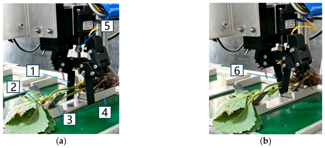
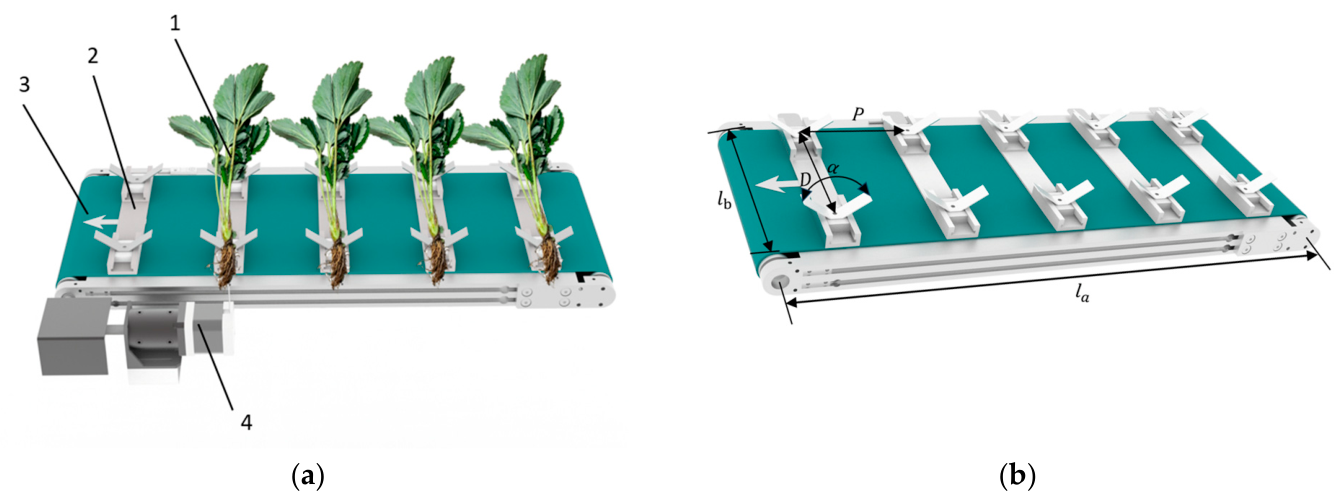
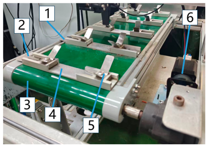
The intermittent conveying device for bare-root strawberry seedlings designed in this study, as shown in
Figure 5a, primarily consists of a conveyor belt with its base and side frames, a stepper motor, double-ended adjustable support frames, a proximity switch, and sensing plates. Serving as the core power source of the conveying system, the output shaft of the stepper motor is coupled with the drive shaft to precisely control the intermittent motion stroke and start-stop logic of the conveyor belt. On the surface of the conveyor belt, multiple double-ended adjustable support frames are fixed at equal intervals along the direction of motion to provide reliable support and posture constraint for the bare-root strawberry seedlings. A proximity switch is fixedly mounted on the side frame of the conveyor belt at the end opposite to the driving end, and the outer side of each support frame is correspondingly equipped with a sensing plate that moves synchronously with it [
27].
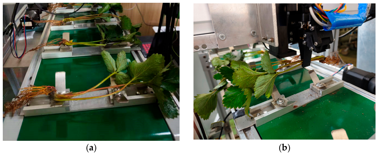
During the manual feeding stage, the bare-root strawberry seedlings are placed transversely on the double-ended adjustable support frames. The roots are uniformly oriented toward the outer support end of the conveyor belt, while the crowns rest on the inner support end, and the seedlings are conveyed forward in a stepping motion. This two-point support layout leaves the central stem area of the bare-root seedling suspended, providing an ample operational window for the end effector. This ensures that the gripper can accurately descend and grasp the seedling at the predetermined gripping point.
Due to the significant variations in length among individual bare-root strawberry seedlings, using a fixed-span support during the conveying process can easily cause shorter seedlings to slip off or the center of gravity of longer seedlings to shift, thereby reducing the success rate of subsequent gripping operations. To address this issue and achieve reliable support and stable posture constraint for bare-root seedlings of varying lengths, a variable-span support mechanism was designed in this study. This mechanism primarily consists of two components: a fixed bracket and an adjustable support slider. The fixed bracket is securely attached directly to the conveyor belt, serving as the reference support end. The adjustable support slider is mounted via a guide rail mechanism, allowing it to slide laterally across the conveyor belt and be locked into the desired position.
The structural parameters of the conveying device are annotated in
Figure 5b. To ensure the stability of the seedling’s center of gravity while keeping the central stem area completely suspended for interference-free gripper operation, the structural parameters of the conveying device must satisfy the following geometric constraints:
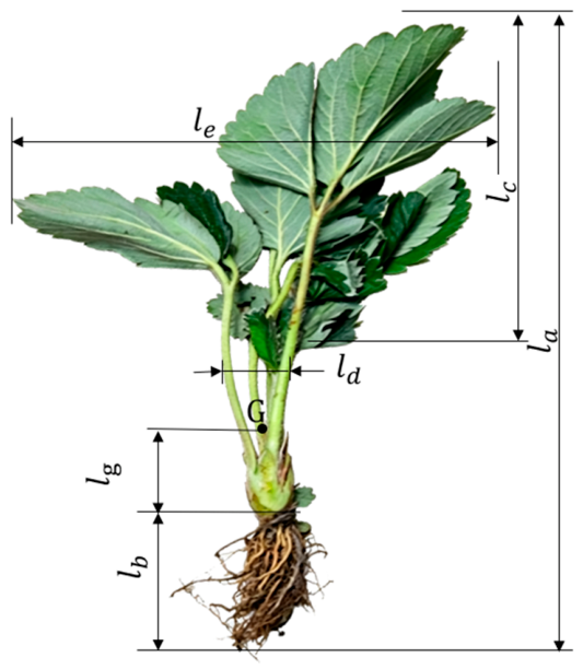
In the formula, —Effective span between the support slider and the fixed bracket, mm; —Length of the bare-root strawberry seedlings in the current operating batch, mm; —Reserved overhang allowance at the outer side of the root, mm; —Overlap allowance of the crown on the outer side of the support slider, mm. —Center installation pitch of adjacent support frames on the conveyor belt, mm; —Maximum limit leaf spread diameter of the bare-root strawberry seedlings, mm; —Redundant safety clearance to prevent physical interference, mm.
2.3.2. Design of Picking End-Effector Based on Seedling Characteristics
The pick-and-place manipulator is the core execution component of the automatic picking and feeding system for bare-root strawberry seedlings, responsible for completing the entire operational process of precisely grasping the bare-root seedlings from the conveying device, transporting them smoothly, and accurately positioning and releasing them into the planting device [
20].
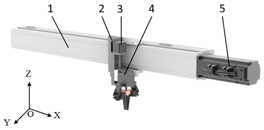
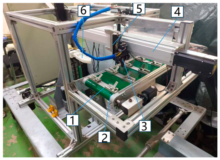
As shown in
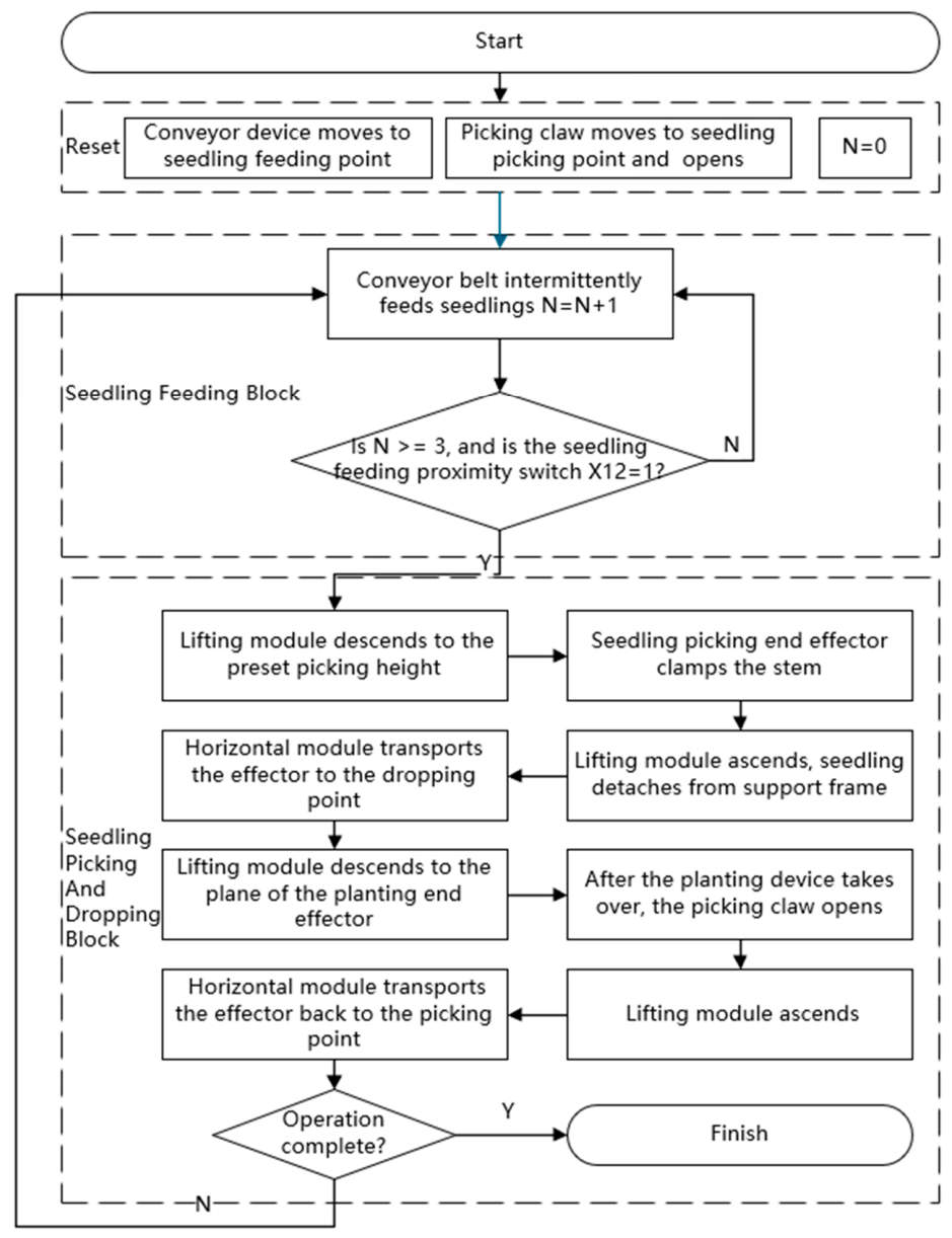
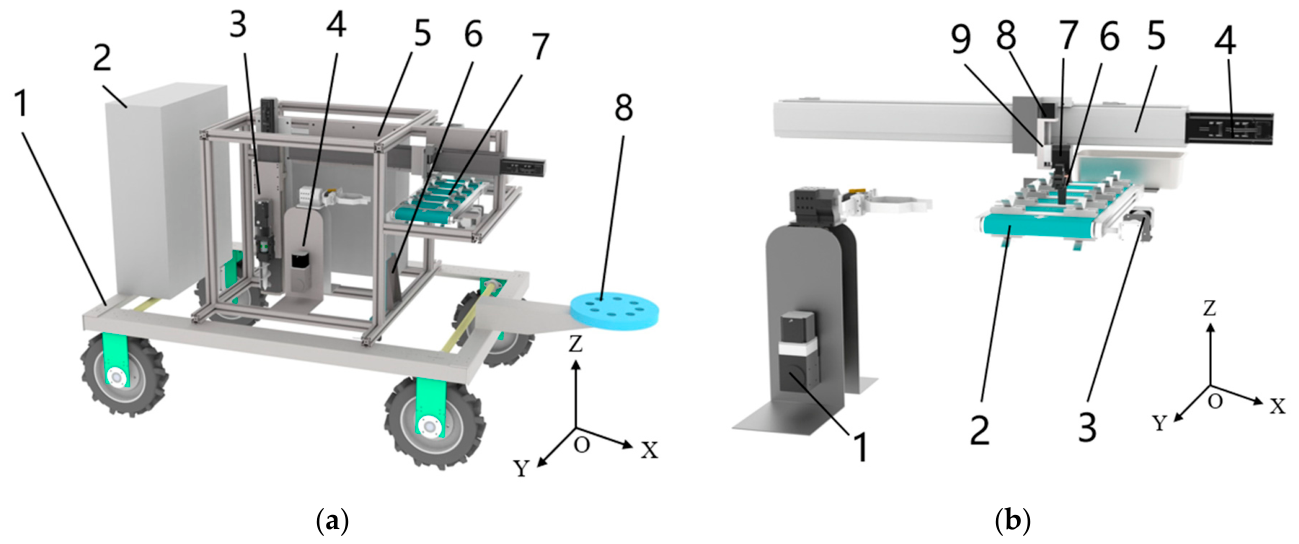
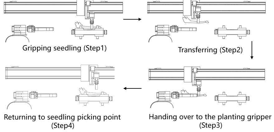
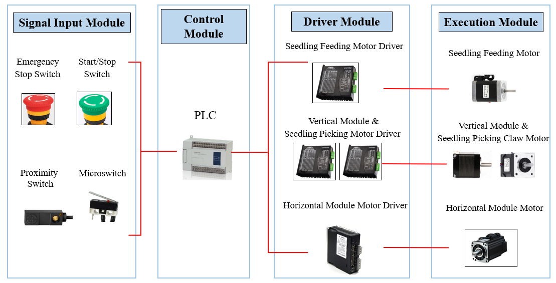
Figure 6, the pick-and-place manipulator mainly consists of three parts: a horizontal motion module, a vertical lifting module, and a seedling-picking end-effector installed at the end of the sliding table of the horizontal module. To meet the precise positioning requirements under high-speed continuous operation, the spatial movement of the manipulator adopts an orthogonal configuration similar to a Cartesian coordinate system, where the horizontal and vertical axes are perpendicular to each other and their movements are mutually independent; the kinematic solution has no coupling, and the trajectory has no singular points, which can ensure high spatial positioning accuracy. According to the requirements of the operational rhythm and span, a ball screw linear guide sliding table mechanism is selected for horizontal movement. This mechanism features high transmission efficiency, high positioning accuracy, and strong structural rigidity. Its power source utilizes a servo motor, transmitting power through components such as couplings, thrust bearings, ball nuts, linear guides, support bearings, and lead screws, in order to satisfy the manipulator’s requirement for high-frequency, high-speed, and smooth long-distance reciprocating transportation between the picking point and the dropping point. The lifting motion stroke is relatively short, primarily responsible for controlling the precise height when the end-effector descends for seedling picking and dropping. Considering the accuracy of point-to-point movement and the need to accommodate morphological differences among different batches of seedlings, this module employs a stepper motor matched with a precision lead screw drive, ensuring the stability and stopping accuracy of the descending and ascending actions in the Z-direction. As the component in direct contact with the bare-root strawberry seedlings, the seedling-picking end-effector utilizes a stepper motor to drive its internal screw slider and symmetric linkage mechanism. Combined with the “gather-first, clamp-later” operational strategy, it achieves non-destructive wrapping and flexible clamping of the root-stem junction of the bare-root strawberry seedlings by precisely controlling the opening/closing angle and motion stroke of the flexible claws, effectively avoiding physical interference and mechanical damage. To ensure the coherence of the fully automatic continuous operation of the entire machine, the pick-and-place manipulator must strictly execute the following seven action sequences within a complete working cycle: “move to picking point
descend for picking
clamp seedling stem
ascend to detach
transport horizontally
descend for dropping
reset”. Based on the comprehensively selected motion forms, the overall working requirements of the machine, and the three-dimensional spatial layout requirements mentioned above, the core kinematic parameters and structural dimensions of each module of the pick-and-place manipulator are selected and configured.
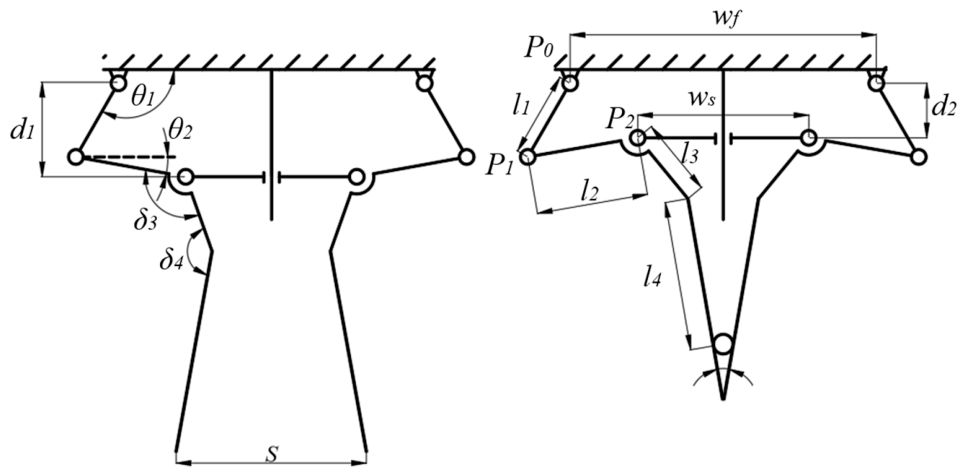
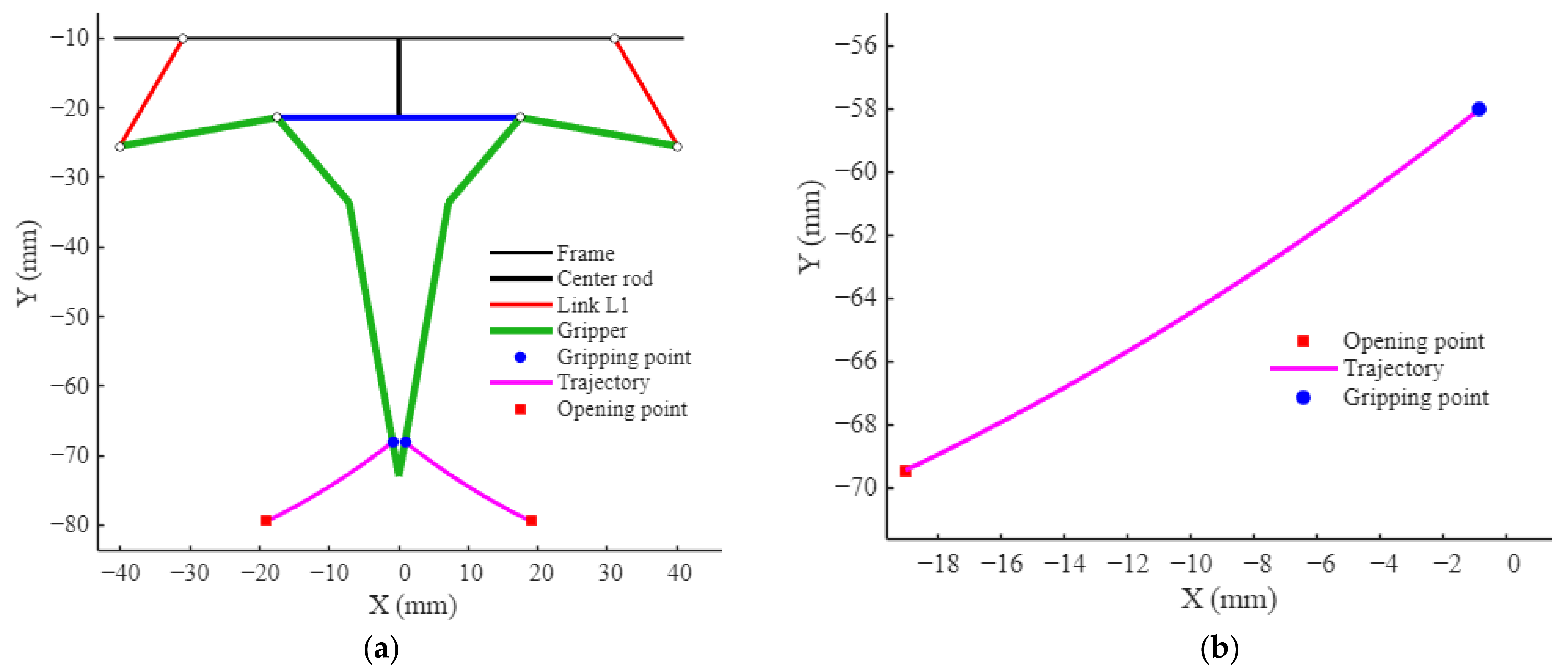
To achieve flexible and non-destructive clamping, this study breaks through the limitations of traditional rigid metal grippers by adopting a flat, straight nylon plate structure for the end-effector claws. The relatively low elastic modulus of nylon endows the claws with excellent bending compliance. The schematic diagram of the seedling-picking end-effector mechanism is shown in
Figure 7. Because the top of the mechanism is suspended by a fixed hinge support, when the stepper motor drives the central slider upward, the claws swing inward symmetrically in an arc around the pivot point. During the closing process, the claws do not remain parallel; instead, as the swing angle changes, their extension lines intersect in space, ultimately forming an inverted V-shaped converging envelope space in the clamped state.
To ensure the successful clamping of the bare-root seedling stems, the following conditions must be met:
(1). The opening degree at the end of the claws must be larger than the maximum measured stem diameter at the upper part of the new stem of the bare-root strawberry seedlings.
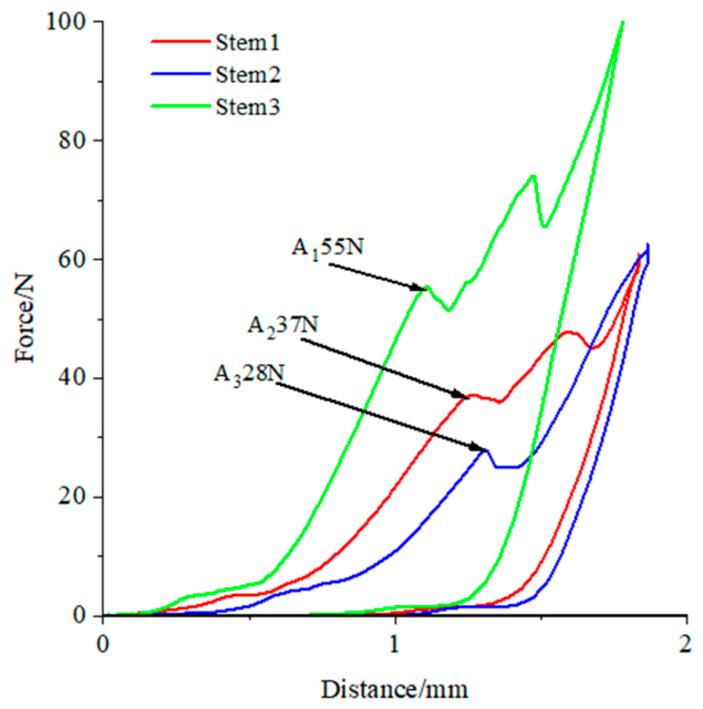
(2). The clamping force must be limited below the physical failure strength of the stem to prevent irreversible mechanical damage.
(3). The maximum static friction generated between the claws and the stem surface must be sufficient to resist the horizontal inertial forces generated during rapid acceleration or sudden stops of the manipulator. Additionally, the claws must provide sufficient anti-overturning frictional torque on the contact surface to counteract the overturning torque that causes the bare-root seedling to tilt to one side due to the eccentricity of its center of gravity during such rapid acceleration or deceleration.
(4). Because the claws form a V-shape when closed, an upward wedge-shaped thrust is also generated. Therefore, the design of the included angle must satisfy the frictional self-locking condition to prevent the seedling from being squeezed outward.
Based on the physical morphology of the stems of bare-root strawberry seedlings, the following gripper motion plan for seedling extraction is designed:
The gripper descends vertically via the Z-axis module in its fully open position. At this stage, the opening distance at the bottom of the dual flat jaws exceeds the natural spread of the three scattered stems. The gripper surrounds the scattered stems in a V-shaped configuration, ultimately stopping at the horizontal plane of the root-stem junction. The stepper motor then drives the slider upward, causing the gripper jaws to swing inward. Because the gripper closes in a converging V-shape, the flat inner walls of the jaws first make contact with the outermost loose stems. By leveraging the tangential guiding force of these flat surfaces, the three splayed stems are forced to slide along the inner walls toward the central axis, gathering into a single bundle. As the mechanism advances, the angle of the dynamic V-shaped space reaches its designated value. The bilateral jaws then fit securely against the outer walls of the bundled stems at an inclined angle, successfully completing the grasping process of the bare-root strawberry seedling.
In order to explore the motion trajectory of the gripping point, kinematic modeling is performed on the mechanism. The schematic diagram of the seedling picking gripper mechanism is shown in
Figure 7. Since the mechanism is symmetrical, the left half is taken for independent modeling. The center point of the top fixed base frame is taken as the origin
. The
X-axis is positive horizontally to the right, and the
Y-axis is positive vertically downward. According to the definition of the coordinate system, the coordinates of the two hinge points on the left are as follows: The left top fixed hinge
:
The left slider moving hinge
:
. The left mechanism is essentially a variation in a slider-crank mechanism. Let the angle between the connecting rod
and the positive direction of the
X-axis be
, and the coordinates of the hinge point
be
:
The hinge point
is located on the slider, and its coordinates satisfy the geometric constraint that the distance between it and
is
:
Substituting
and
into the equation and expanding:
Let the constant
:
After rearranging, a trigonometric equation for
can be obtained:
After calculating
, the exact coordinates
of
can be determined. Subsequently, it is necessary to calculate the spatial pose of the connecting rod
(i.e., the absolute angle
of the vector
), because the gripper fingertip is fixed to the extended structure of
:
According to the diagram, the gripper finger is a single rigid body containing
,
, and
.
and
are converted into fixed structural angles relative to the vector
. Let the structural deflection angle of
relative to
be
, and the structural deflection angle of
relative to
be
. The coordinates
of the fingertip point
at the end of the left gripper are:
Since the mechanism is completely symmetrical, the total opening degree is twice the absolute value of the left fingertip’s X-coordinate: .
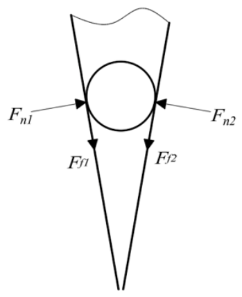
To avoid damaging the strawberry bare-root seedling during the gripping process, the seedling is treated as a cylinder for force analysis, as shown in
Figure 8. During the transient process when the gripper finally closes and compresses the root-stem junction, an angle exists between the two gripper jaws, and a force analysis is conducted on this configuration.
Since the working surface of the gripper is flat, the stem is treated equivalently as a cylinder with a radius of
. Therefore, the gripping model is microscopically simplified into a bilateral line contact problem. Let the normal squeezing forces exerted by the unilateral gripper jaws on the stem epidermis be
and
, and the contact length be
. According to the Hertz contact theory, the elastic modulus is
, and the equivalent radius of curvature of the system is
. Then the maximum microscopic contact stress
on the central axis of the contact surface is:
The stress distribution of the gripper contact is highly concentrated. To prevent the local from exceeding the physical failure strength of the strawberry epidermal cells, it is necessary to limit the magnitude of the normal force .
Assume that in the final clamping position, the included angle between the two flat gripper jaws is
. Let the normal positive pressure perpendicular to the jaw surface ultimately transmitted by the driving mechanism to the gripper be
. Because the gripper jaws are inclined, the normal force
will generate an upward wedge thrust component
in the vertical direction:
At the moment of clamping, this vertical upward resultant force
can easily cause the seedling to slip upward along the gripper jaws. To ensure that the seedling is not “squeezed out”, the maximum static friction force generated on the surface of the gripper jaws must be able to counteract this wedge component force. Let the coefficient of static friction between the gripper jaws and the strawberry epidermis be
. According to Coulomb’s law of friction, the total maximum static friction force on the bilateral planes is
. The necessary and sufficient physical self-locking condition to prevent axial slipping at the moment of clamping is:
The tangent of the half-angle of the final V-shaped included angle between the two flat jaws must be less than or equal to the experimentally measured material static friction coefficient .
Once self-locking clamping is completed, the manipulator will enter the 3D spatial transportation stage. At this time, the seedling is subjected to the combined effect of gravity
and horizontal inertial force
. To prevent the seedling from falling off during high-speed spatial transfer, the resultant force of the friction force and the vertical normal component force must overcome the external dynamic load:
During the horizontal transportation process, an eccentricity
exists between the center of gravity and the gripping center. To prevent the seedling from tilting in its posture during high-speed transportation, the gripper must provide sufficient anti-overturning friction torque at the effective contact surface with the stem. The maximum anti-overturning friction torque
that can be provided under the combined action of the bilateral gripper jaws is:
To ensure the absolute vertical stability of the seedling during the spatial transfer process, it is necessary to satisfy the condition that the anti-overturning friction torque is greater than or equal to the overturning torque, i.e.,
, from which the lower limit constraint condition of the normal gripping force to prevent deflection can be derived:
Combining the equations with the
biological yield red line for radial compression of the plant, the full-process gripping conditions under this dual-jaw V-shaped spatial architecture are ultimately established as follows: