Article

Performance Analysis and Experimental Validation of Small-Radius Slope Steering for Mountainous Crawler Tractors

1
College of Mechanical and Electronic Engineering, Northwest A&F University, Yangling 712100, China
2
Ministry of Agriculture and Rural Affairs Apple Full Mechanization Research Base, Yangling 712100, China
3
Scientific Observation and Experimental Station of Agricultural Equipment for the Northern China Ministry of Agriculture and Rural Affairs, Yangling 712100, China
4
Agricultural Mechanization Technology Extension Station of Ningxia Hui Autonomous Region, Yinchuan 750000, China
*
Author to whom correspondence should be addressed.
Agronomy 2025, 15(8), 1956; https://doi.org/10.3390/agronomy15081956
Submission received: 9 July 2025 / Revised: 11 August 2025 / Accepted: 12 August 2025 / Published: 13 August 2025
(This article belongs to the Special Issue Unmanned Farms in Smart Agriculture—2nd Edition)

Abstract

This study investigates the dynamic performance of mountainous crawler tractors during small-radius slope steering, providing theoretical support for power machinery design in hilly and mountainous regions. Addressing the mechanization demands in complex terrains and existing research gaps, a steering dynamics model is established. The model incorporates an amplitude-varied multi-peak cosine ground pressure distribution, employs position vectors and rotation matrices to characterize 3D pose variations in the tractor’s center of mass, and integrates slope angle, soil parameters, vehicle geometry, center-of-mass shift, bulldozing resistance, and sinkage resistance via d’Alembert’s principle. Numerical simulations using Maple 2024 analyzed variations in longitudinal offset of the instantaneous steering center, bilateral track traction forces, and bulldozing resistance with slope, speed, and acceleration. Variable-gradient steering tests on the “Soil-Machine-Crop” Comprehensive Experimental Platform demonstrated model accuracy, with <8% mean error and <12% maximum relative error between predicted and measured track forces. This research establishes a theoretical foundation for predicting, evaluating, and controlling the steering performance/stability of crawler tractors in complex slope conditions.

1. Introduction

Hilly and mountainous regions serve as critical production bases for grain, oil crops, sugar, and specialty agricultural products in China. Statistical data (2024) indicate these areas comprise 34.62% of the nation’s cultivated land area and 34.20% of total sown acreage [1]. However, the comprehensive farming mechanization level (covering tillage, planting, and harvesting operations) lags 22 percentage points below the national average and 34 points behind plain regions [1]. Agricultural mechanization development is constrained by steep gradients, confined pathways, and fragmented land parcels—terrain characteristics imposing stringent requirements on gradeability and steerability of hillside tractors [2,3,4]. Crawler tractors achieve steering by actively controlling the speed differential between bilateral tracks, a method called differential speed steering [5]. This approach enables small-radius steering maneuvers; when tracks move at equal speeds in opposite directions, the tractor performs zero-radius steering (theoretical turning radius = 0), significantly reducing required maneuvering space. In contrast, wheeled tractors suffer from compromised maneuverability in confined plots due to mechanical constraints of front-axle steering. Furthermore, crawler tractors feature superior terrain adaptability, including lower ground contact pressure, enhanced tractive adhesion and exceptional gradeability and obstacle-crossing capabilities [6,7,8]. Consequently, mountainous crawler tractors (MCTs) have become the predominant power machinery in hilly and mountainous regions. Nevertheless, slope steering dynamics diverge fundamentally from level-ground steering due to gravitational inclination effects, presenting significant challenges for steering system design.
During slope steering maneuvers, crawler vehicles exhibit distinct dynamic characteristics compared to level-ground steering due to gravitational components parallel to the inclined surface [9], concurrently altering ground contact pressure distributions across bilateral tracks. Sun et al. [10] established slope steering dynamics equations based on linearly distributed ground pressure, revealing progressively intensified pressure variations with increasing slope angles. Shi et al. [11] demonstrated that instantaneous steering center offset significantly influences crawler vehicle slope steering, where steeper inclinations exacerbate tail-swing and over-steering phenomena. Increased slope angles amplify tractive force divergence between inner/outer tracks, while at lower velocities, power requirements exhibit consistent trends with tractive force variations [12]. Zhang et al. [13] developed an improved tank dynamics model incorporating Wong’s [14] shear stress–displacement relationships, evaluating structural parameter impacts through track slip rate metrics. Dong et al. [15] formulated an articulated crawler vehicle slope steering model validated via virtual simulation and field experiments. However, this model oversimplifies ground pressure as linear distributions and neglects sinkage resistance, limiting accuracy in complex terrain. Agricultural crawler vehicles predominantly operate on soft soils where sinkage resistance substantially affects steering performance. Although Jia et al. [16] established a soft-slope steering model considering sinkage resistance to analyze slope angle and turning radius effects, their research omitted bulldozing resistance—a critical factor in track-terrain interactions.
Current predictive models for crawler vehicle slope steering [17,18,19,20] primarily focus on track–terrain shearing relationships, often assuming linearly or multi-rectangularly distributed ground contact pressures. These simplifications deviate from actual operating conditions. During slope steering on deformable soils, ground contact pressures typically exhibit non-uniform, nonlinear distributions [21]. Zhao et al. [22] characterized multi-peak pressure distributions along the track length using quadratic cosine functions, incorporating peak-connection functions and trough allocation coefficient β to represent soil hardness. Their experiments verified that increased loads promote more uniform multi-peak distributions. Tang et al. [23] idealized contact pressure as bi-trapezoidal distributions, introducing an under-steer parameter to evaluate steering stability. Zhang et al. [24] employed adjustable-peak cosine functions to fit contact pressures under road wheels, simplifying steering dynamics by adapting wheeled vehicle tire slip angle principles. Despite these advances, existing contact pressure models remain predominantly developed for level-ground conditions, lacking validated formulations for sloped terrain in hilly and mountainous regions.
In summary, current research on crawler vehicle slope steering predominantly addresses large-radius maneuvers, with limited focus on small-radius steering performance. To establish a high-precision predictive model for MCTs operating under complex slope conditions in hilly terrain, this study
  • Refines ground contact pressure models by incorporating slope-induced center-of-mass displacement effects across varying inclinations and operational scenarios;
  • Formulates a small-radius steering dynamics model for deformable slopes based on enhanced pressure distributions;
  • Validates the model through experimental trials conducted on the integrated “Soil-Machinery-Crop” test platform specifically designed for hilly terrain applications.
This framework demonstrates applicability and effectiveness for analyzing slope steering performance in complex mountainous environments, establishing theoretical foundations encompassing (1) design optimization of steering mechanisms, (2) performance assessment protocols, and (3) control strategy development for crawler-based power machinery in hilly regions.

2. Materials and Methods

This section details the mechanical model of MCTs during small-radius slope steering. First, four steering conditions are categorized based on azimuth angles, establishing coordinate systems to derive the 3D pose of the center of mass and pressure center offset. Second, six-degree-of-freedom dynamic equations are formulated using d’Alembert’s principle, innovatively employing an amplitude-varied multi-peak cosine function to characterize ground contact pressure distribution on slopes. The model integrates bulldozing resistance, sinkage resistance, and frictional forces. Finally, numerical simulations are performed in Maple 2024 with specific vehicle parameters. This model provides a theoretical foundation and technical support for predicting and analyzing MCT steering performance on sloped terrain.

2.1. Kinematics Model for Small-Radius Slope Steering of MCTs

2.1.1. Definition and Classification of Typical Operational Scenarios for Small-Radius Steering

During slope steering operations of mountainous crawler tractors, steering scenarios are classified by turning radius R into large-radius and small-radius steering. Small-radius steering occurs when R ∈ [0, B/2] (where B denotes track gauge), while large-radius steering corresponds to R ∈ (B/2, +∞). This study exclusively focuses on small-radius slope steering of MCTs.
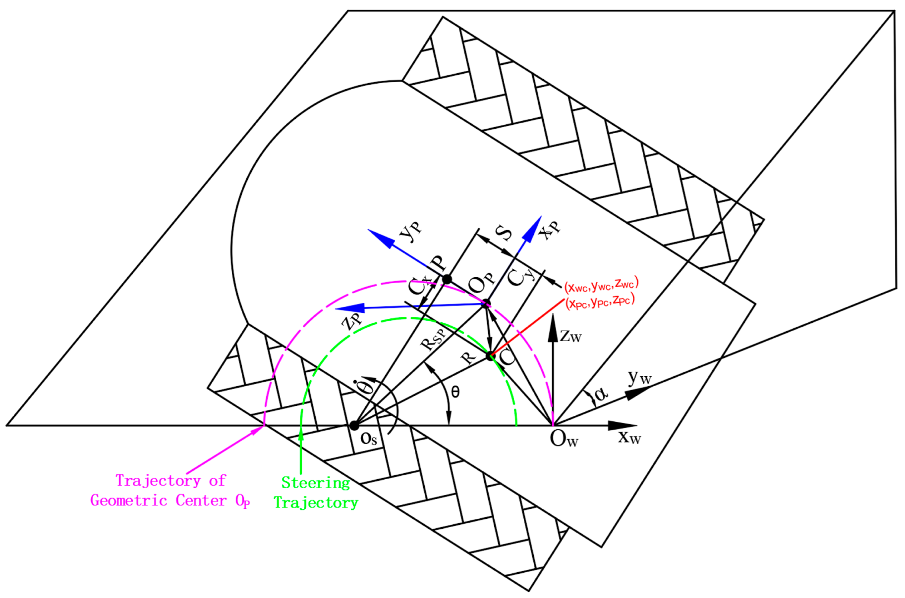
During small-radius slope steering of MCTs, longitudinal forces (induced by ground inclination) and lateral forces (caused by cross-slope or contour-aligned gradients) significantly impact vehicle dynamics. This shifts the normal pressure distribution center away from the tractor’s geometric center, resulting in lateral and longitudinal offsets. For analytical clarity, this study categorizes slope steering into four operational scenarios based on azimuth angles (θ = 0~360°) in Figure 1:
  • Quadrant I (0° < θ ≤ 90°): Uphill steering on longitudinal slopes (red zone);
  • Quadrant II (90° < θ ≤ 180°): Downhill steering on contour-aligned slopes (yellow zone);
  • Quadrant III (180° < θ ≤ 270°): Downhill steering on longitudinal slopes (green zone);
  • Quadrant IV (270° < θ ≤ 360°): Uphill steering on contour-aligned slopes (cyan zone).
Longitudinal slopes refer to travel paths aligned with the fall line of inclined terrain, while contour-aligned directions represent movement paths orthogonal to longitudinal slopes (longitudinal ⊥ contour). Steering direction follows the counterclockwise orientation.

2.1.2. Fundamental Assumptions and Coordinate System Establishment

Numerous factors influence small-radius slope steering performance of crawler tractors. To streamline analysis and clarify research scope, the following assumptions are established:
  • Based on China’s Third National Land Survey, steep slopes > 25° constitute 4.2252 million hectares (63.3783 million mu), representing merely 3.31% of total cultivated area [25]. Such gradients are unsuitable for agricultural operations and continue to diminish annually. Therefore, operational slope angles are constrained to 0~25°.
  • Slopes are idealized as planar surfaces with tractors performing steady-state steering.
  • Variations in track tension due to grounding segment deformation are neglected.
  • Pitching and rolling motions affecting steering dynamics are disregarded—vehicles rotate solely about the normal axis perpendicular to the slope surface.
  • Shearing internal resistance is omitted given minimal shear displacement variations within track–soil contact regions during steering.
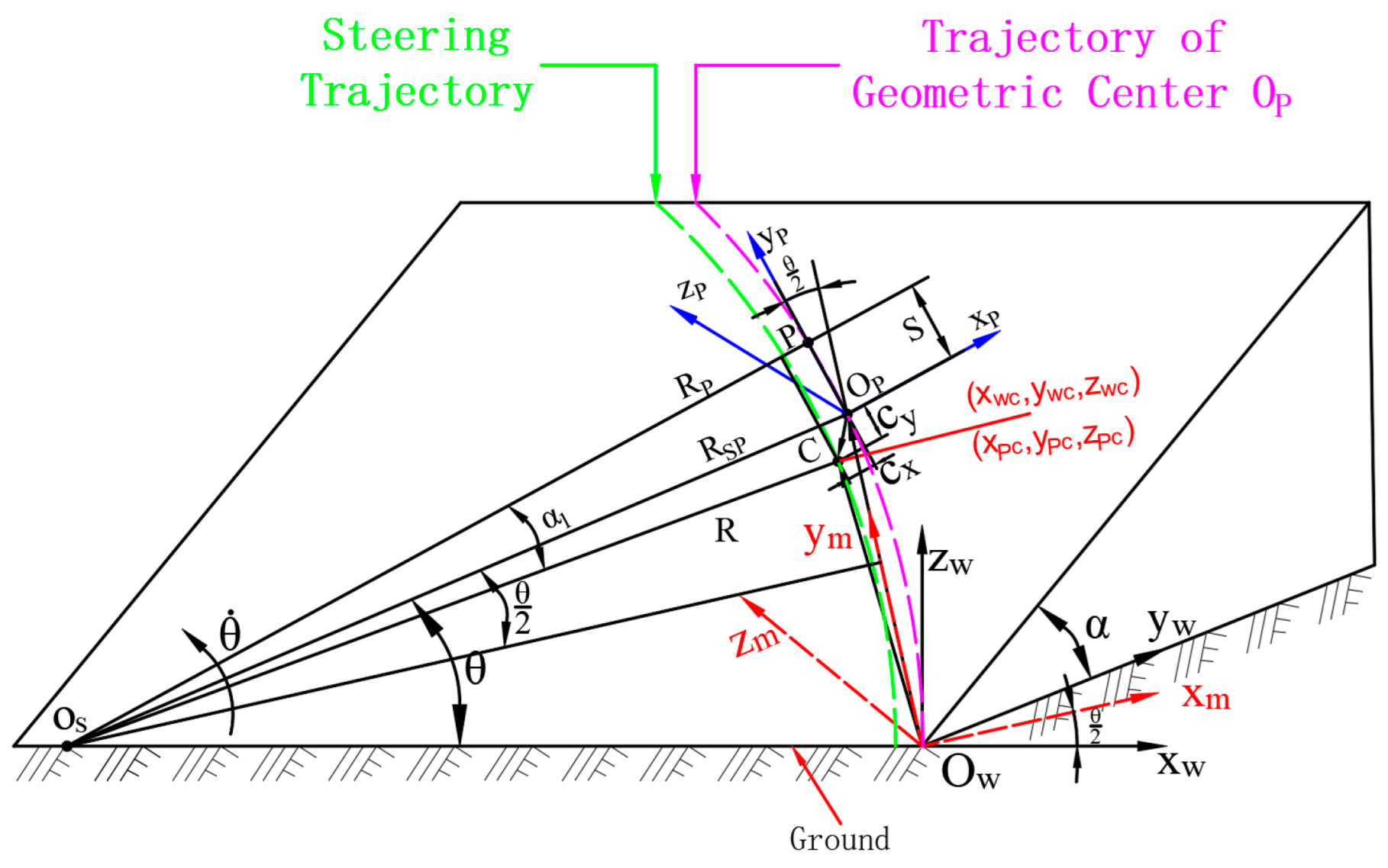
Figure 2 illustrates the kinematic model of a MCTs during small-radius slope steering.
  • α: Slope inclination angle;
  • θ: Vehicle steering angle;
  • OS: Steering center;
  • C: Pressure center (projection of center of mass onto slope surface);
  • R: Actual turning radius;
  • RSP: Distance from OS to OP;
  • RP: Projection of pressure center C onto OSP axis;
  • θ ˙ : Steering angular velocity;
  • Cx: Lateral deviations of pressure center relative to geometric center;
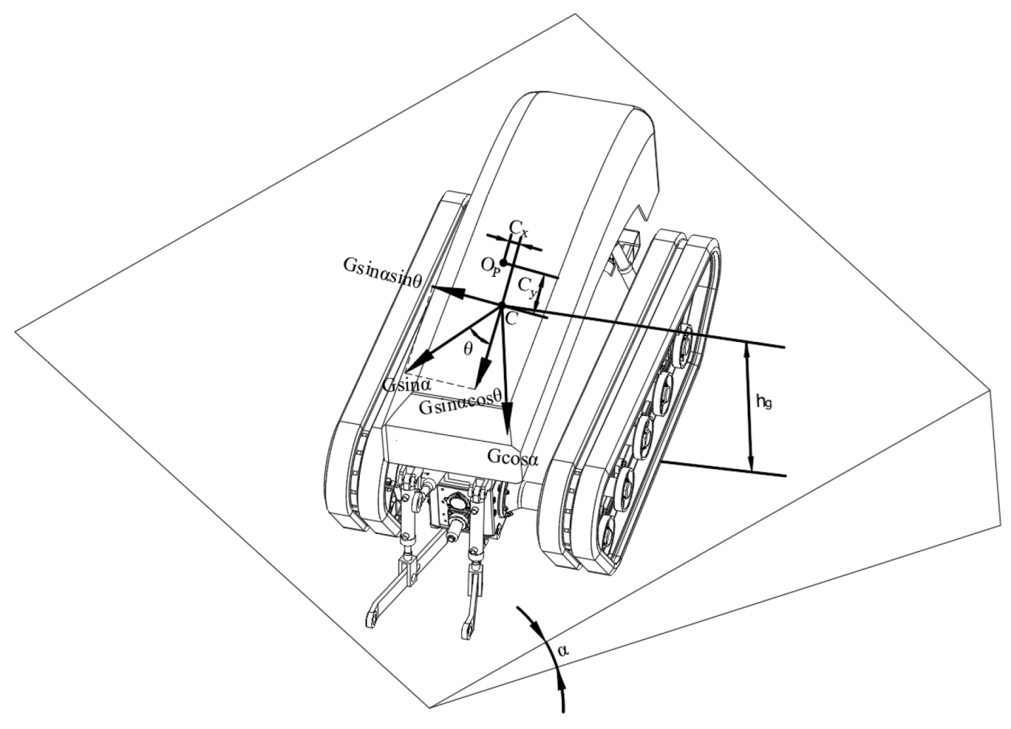
Cy: Longitudinal deviations of pressure center relative to geometric center.To characterize the pose of mountainous crawler tractors during small-radius slope steering, coordinate systems are established as shown in Figure 3:
  • World coordinate system Ow-xwywzw fixed to ground.
  • Local coordinate system Op-xpypzp rigidly attached to the tractor, where Op denotes the geometric center of the tractor’s projection on the slope surface.
Key parameters:
Steering kinematics involve composite motion: The tractor body rotates about point OS while simultaneously undergoing rotation about the instantaneous steering center. The pose transformation of {P} occurs in two phases:
  • Transition from level ground to slope: Coordinates rotate α° about the xP -axis (yP and zP axes transformation);
  • Slope steering about OS: Coordinates rotate θ° about the zP -axis (xP and yP axes transformation).
Based on vector relationships and coordinate transformation principles in Figure 3, the position of pressure center C after θ° rotation in {W} is given by:
r c = O W C W = O W O P W + R P W O P C P
where WOWC represents the position of point C in coordinate system {W}, WOWOP represents the position of point OP in coordinate system {W}, R P W denotes the rotation matrix expressing the orientation of coordinate system {P} relative to coordinate system {W}, and POPC represents the position of point C in coordinate system {P}.
The relationship between coordinate systems {W} and {P} is defined using Euler angles. The inherent angles of a tractor include the pitch angle α (°), roll angle β (°), and yaw angle θ (°). The rotation matrices about each coordinate axis are given by
R x , α = 1 0 0 0 c o s α s i n α 0 s i n α c o s α             R y , β = c o s β 0 s i n β 0 1 0 s i n β 0 c o s β             R z , θ = c o s θ s i n θ 0 s i n θ c o s θ 0 0 0 1
To compute vector WOWOP, a spatial coordinate system Ow-xmymzm (i.e., {M}) is established sharing the origin with the world coordinate system {W}. With reference to the transformation relationships between coordinate systems in Figure 3, the vector expression for WOWOP is derived as follows:
O W O P W = R x , α R z , θ 2 0 , 2 R S P s i n θ 2 , 0 T = 1 0 0 0 c o s α s i n α 0 s i n α c o s α c o s θ 2 s i n θ 2 0 s i n θ 2 c o s θ 2 0 0 0 1 0 , 2 R S P s i n θ 2 , 0 T
The vector O P C P can be represented by the coordinates [xPC,yPC,zPC]T of the center of mass C in the {P} frame. For tractors with invariant structural configuration (neglecting relative motion of internal components), this vector is assumed invariant. The rotation matrix is expressed based on the pose transformation of {P} as
R P W = R x , α R z , θ = c o s θ s i n θ 0 c o s α   s i n θ c o s α   c o s θ s i n α s i n α   s i n θ s i n α   c o s θ c o s α
Substituting Equations (2)–(4) into Equation (1) yields the coordinates of point C in the world coordinate system {W} after the tractor rotates θ° about OS:
r c = O W C W = x W C , y W C , z W C = R x , α   R z , θ 2   0 , 2 R S P s i n θ 2 , 0 T + R P W x P C , y P C , z P C T = 1 0 0 0 c o s α s i n α 0 s i n α c o s α c o s θ 2 s i n θ 2 0 s i n θ 2 c o s θ 2 0 0 0 1 0 2 R S P sin θ 2 0 + 1 0 0 0 c o s α s i n α 0 s i n α c o s α c o s θ s i n θ 0 s i n θ c o s θ 0 0 0 1 x P C y P C z P C
= R S P c o s θ 1 cos α   sin θ sin α   sin θ + c o s θ s i n θ 0 c o s α   s i n θ c o s α   c o s θ s i n α s i n α   s i n θ s i n α   c o s θ c o s α x P C y P C z P C

2.1.3. Solving for Vehicle Steering Motion Parameters

RP can be expressed as
R P = R 2 C y + S 2
where S denotes the longitudinal offset of the instantaneous steering center.
RSP can be expressed as
R S P = R P + C x 2 + S 2
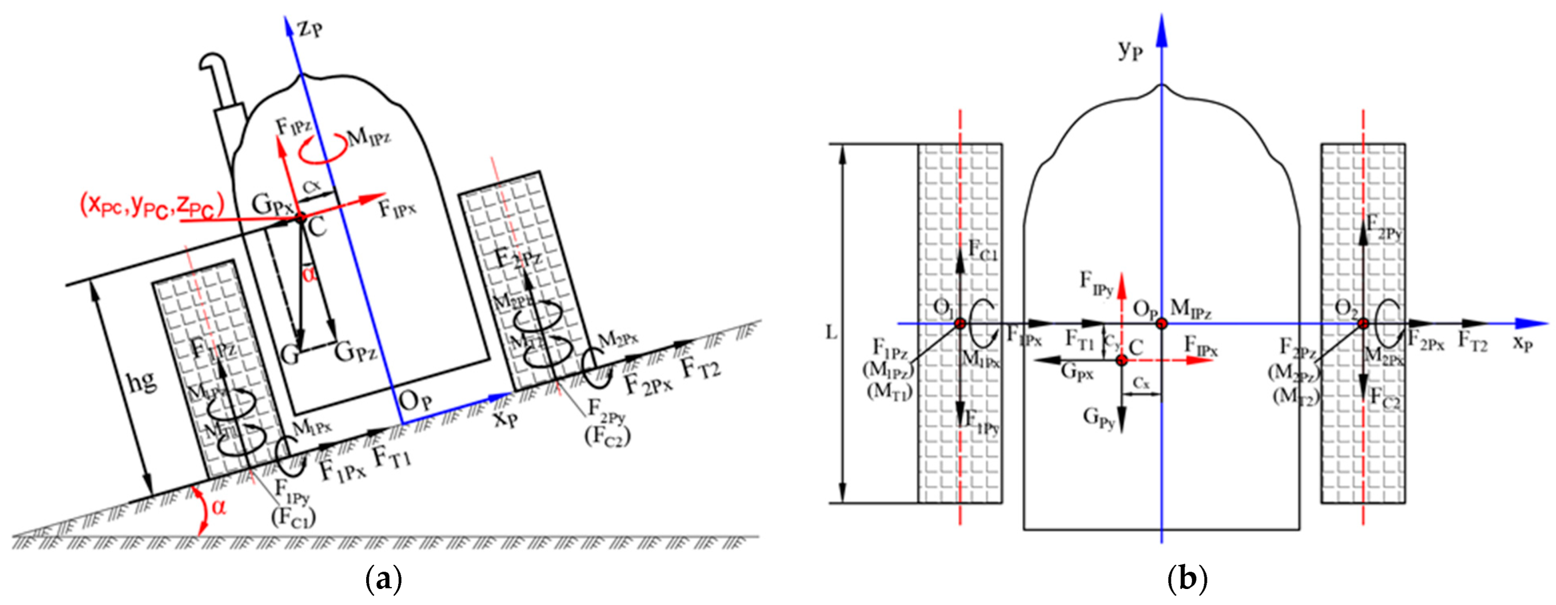
As illustrated in Figure 4, during small-radius slope steering of the tractor, gravitational effects induce lateral and longitudinal offsets (Cx and Cy) at the pressure center. These offsets can be determined by taking moments of point OP.
G   s i n α   s i n θ h g = G   c o s α C x G   s i n α   c o s θ h g = G   c o s α C y
Solving for Cx and Cy yields
C x = h g t a n α   s i n θ C y = h g t a n α   c o s θ
where hg denotes the height of the center of mass.
Substituting Equations (6)–(9) into Equation (5) yields
r c = R 2 h g t a n α   c o s θ + S 2 + h g t a n α   s i n θ 2 + S 2 × c o s θ 1 cos α   sin θ sin α   sin θ + c o s θ s i n θ 0 c o s α   s i n θ c o s α   c o s θ s i n α s i n α   s i n θ s i n α   c o s θ c o s α x P C y P C z P C
The coordinates (xPC, yPC, zPC) of point C in the {P} frame are invariant for tractors with invariant structural configurations.
To facilitate subsequent derivation, Equation (10) may be expressed in the following form, where RSP, M1, M2, M3 are defined in Appendix A.
r c = R S P   M 1 + M 2 × M 3
Given the steering angle θ as a function of time t, the first and second derivatives of Equation (10) with respect to time yield the velocity vc and acceleration ac of the center of mass during small-radius slope steering:
v c = d r c d t = θ ˙ R S P M 1 + R S P M 1 + θ ˙ M 2 M 3
a c = d 2 r c d t 2 = θ ¨ R S P M 1 + R S P M 1 + θ ˙ 2 R S P M 1 + 2 R S P M 1 + R S P M 1 + θ ¨ M 2 + θ ˙ 2 M 2 M 3
The steering angular velocity and angular acceleration during small-radius slope steering of the tractor can be expressed as
θ ˙ = v R ;             θ ¨ = a R
where v denotes the traveling speed of the tractor, and a represents its traveling acceleration.
Given specified parameters, Equations (11)–(13) are functions of turning radius R, steering angle θ, angular velocity θ ˙ , and angular acceleration θ ¨ . For tractors with invariant structural configurations, the steering resistance moment is primarily governed by two factors:
  • Variations in vehicle motion parameters (e.g., turning radius, azimuth angle, angular velocity, angular acceleration) alter the magnitude and direction of terrain reaction forces on tracks;
  • Shifts in the pressure center redistribute normal loads over the track-ground contact segment, consequently modifying the distribution of steering resistance.
The following analysis addresses the dynamics of small-radius slope steering and derives corresponding computational formulae.

2.2. Dynamics Model for Small-Radius Slope Steering of MCTs

2.2.1. Formulation of Dynamics Equations

As the small-radius slope steering of MCTs constitutes a spatial composite motion, it necessitates the formulation of six dynamics equations (three for translational motion and three for rotational motion). These equations aim to determine the required input forces or torques based on the vehicle’s steering behavior. To streamline the modeling process and facilitate analysis, a local coordinate frame (i.e., the moving frame {P}) is adopted as the reference frame. During steady-state steering, all external forces and torques maintain equilibrium at the geometric center OP. In accordance with dynamics principles, the dynamics equations are established along each axis of frame {P}, with their general form expressed as
F = m   a P c
M = J O P   θ ¨ P
where F denotes the external force applied to the tractor, m is the gross vehicle mass, JOP represents the moment of inertia about the zP-axis passing through point OP, aPc is the absolute acceleration of the vehicle’s center of mass in frame {P}, and θ ¨ P denotes the angular acceleration of the vehicle in frame {P}.
Based on coordinate transformation principles, the vecto ac can be projected onto frame {P} as
a P c = a P c x a P c y a P c z = R 1 P W a c x a c y a c z = c o s θ c o s α   s i n θ s i n α   s i n θ s i n θ c o s α   c o s θ s i n α   c o s θ 0 s i n α c o s α a c x a c y a c z
The vector vc can be projected onto {P} as:
v P c = v P c x v P c y v P c z = R 1 P W v c x v c y v c z = c o s θ c o s α   s i n θ s i n α   s i n θ s i n θ c o s α   c o s θ s i n α   c o s θ 0 s i n α c o s α v c x v c y v c z
The angular acceleration θ ¨ P in the frame {P} is expressed as
θ ¨ P = a P c R
Figure 5 illustrates the simplified force analysis of a mountainous crawler tractor during small-radius slope steering. The primary external forces acting on the tractor include
  • Gravity G;
  • Inertial force FC;
  • Sinkage resistance FC1, FC2 at track-terrain contact segments;
  • Tractive effort F1Py and F2Py at track-terrain contact segments (acting in opposite directions during small-radius steering);
  • Lateral frictional resistance F1Px, F2Px on soft terrain;
  • Bulldozing resistance FT1, FT2 along track sides;
  • Equivalent normal loads F1Pz, F2Pz from terrain;
  • Resistance moments M1Px, M2Px in the xP- direction;
  • Frictional resistance moments M1Pz, M2Pz and bulldozing resistance moments MT1, MT2 in the zP- direction.
All forces and moments are assumed to act at the center of track-terrain contact. Inertial forces FIPx, FIPy, FIPz and inertial moment MIPz are depicted in Figure 5a,b.
Inertial force can be expressed as
F I P x F I P y F I P z = m a P c = m c o s θ c o s α   s i n θ s i n α   s i n θ s i n θ c o s α   c o s θ s i n α   c o s θ 0 s i n α c o s α a c x a c y a c z
Inertial moment can be expressed as
M I P z = J I P z   θ ¨ P z
where JIPz denotes the moment of inertia about the zP-axis during slope steering, and θ ¨ P z represents the angular acceleration about the zP-axis in frame {P}.
According to Equation (19), the angular acceleration θ ¨ P z about the zP-axis in frame {P} can be expressed as
θ ¨ P z = a P c z R
The gravity vector G in frame {W}, denoted as [GWx, GWy, GWz]T, can be expressed as [0, 0, −G]T, which is then transformed to frame {P}.
G P x G P y G P z = R 1 P W G W x G W y G W z = c o s θ c o s α s i n θ s i n α s i n θ s i n θ c o s α c o s θ s i n α c o s θ 0 s i n α c o s α 0 0 G = G sin α sin θ sin α cos θ cos α
G = m   g
where JIPz denotes the moment of inertia about the zP-axis during slope steering, and θ ¨ P z represents the angular acceleration about the zP-axis in frame {P}.
where g is the gravity acceleration, taken as 9.8 m/s2.
Based on D’Alembert’s principle, the dynamic equations for tractor slope steering are established in the relative frame {P}, with the rearranged forms of Equations (15) and (16) given as follows:
F P x = 0 F 1 P x + F 2 P x + F T 1 + F T 2 G P x + F I P x = 0
F P y = 0 F 2 P y + F C 1 F 1 P y F C 2 G P y + F I P y = 0
F P z = 0 F 1 P z + F 2 P z G P z + F I P z = 0
M P x = 0 M 1 P x + M 2 P x + G P y z P C F I P y z P C + G P z y P C F I P z y P C = 0
M P y = 0 F 1 P z B 2 F 2 P z B 2 G P x z P C + F I P x z P C G P z x P C + F I P z x P C = 0
M P z = 0 M 1 P z + M 2 P z + M T 1 + M T 2 + F 1 P y + F 2 P y F C 1 F C 2 B 2 + G P y x P C F I P y x P C G P x y P C + F I P x y P C M I P z = 0
where B is the gauge of the mountain crawler tractor.
M1Px, M2Px, M1Pz, M2Pz can be expressed, respectively, as
M 1 P x = F 1 P z   e 1 P y                               M 2 P x = F 2 P z   e 2 P y M 1 P z = μ F 1 P z   e 1 P y                               M 2 P z = μ F 2 P z   e 2 P y
where e1Py is the longitudinal offset between the equivalent normal load F1Pz and the center of the contact patch for the corresponding track, e2Py is the longitudinal offset between the equivalent normal load F2Pz and the center of the contact patch for the corresponding track, and μ is the steering resistance coefficient.
The steering resistance coefficient μ can be calculated by the empirical Formula given in Reference [26].
μ = μ 0 1 + 2 R B U
where μ0 is the maximum steering resistance coefficient during on-the-spot steering of the tractor, experimentally determined in [1] and taken as 0.9; U is the track tension index ranging from 0.2 to 0.5. Given that mountain crawler tractors operate on soft terrain with relatively uniform pressure distribution, U should take a larger value, here taken as 0.4.
Given the kinematic parameters, vehicle mass, center of mass position, and moment of inertia about the zP-axis, there are nine unknowns in Equations (25)–(30). Therefore, corresponding supplementary equations need to be established.
First, by substituting Equation (20) into Equations (27) and (29) and solving them simultaneously, the vertical forces F1Pz and F2Pz are obtained as
F 1 P z = G P z m   a P c z 2 + x P C G P z m   a P c z + z P C G P x m   a P c x B
F 2 P z = G P z m   a P c z 2 x P C G P z m   a P c z + z P C G P x m   a P c x B
In Equation (28), M1Px and M2Px are the simplified moments resulting from reducing the normal loads F1Pz and F2Pz to the centers of the contact patches for their respective tracks. Based on the condition that the twist angles about the xP-axis are equal for the inner and outer tracks during steady-state steering of the tractor, supplementary equations are established.
M 1 P x × B 2 x P C G I P = M 2 P x × B 2 + x P C G I P
where GIp is the torsional stiffness of the tractor.
By solving Equations (28) and (35) simultaneously, we obtain
M 1 P x = 1 2 + x P C B G P y m   a P c y z P C + y P C G P z m   a P c z
M 2 P x = 1 2 x P C B G P y m   a P c y z P C + y P C G P z m   a P c z
Thus, the expressions for the longitudinal offsets e1Py and e2Py of the normal loads on the inner and outer tracks can be obtained.
e 1 P y = M 1 P x F 1 P z = B + 2 x P C z P C m   a P c y G P y + y P C m   a P c z G P z B + 2 x P C m   a P c z G P z + 2 z P C m   a P c x G P x
e 2 P y = M 2 P x F 2 P z = B 2 x P C z P C m   a P c y G P y + y P C m   a P c z G P z B 2 x P C m   a P c z G P z 2 z P C m   a P c x G P x
The sign of the longitudinal offsets e1Py and e2Py indicates the fore–aft relationship of the equivalent normal loads F1Pz and F2Pz relative to the centers of the contact patches for the inner and outer tracks. A positive value denotes that the load acts anterior to the contact patch center, while a negative value indicates a posterior position. Simultaneously, these longitudinal offsets govern the distribution of ground contact pressure. During slope steering with small turning radii of MCTs, lateral and longitudinal shifts in the pressure center cause markedly non-uniform contact pressure distributions on the inner and outer tracks, consequently influencing lateral resistance distribution.

2.2.2. Track Contact Pressure Distribution

Due to variations in the number of road wheels and suspension configurations among crawler tractors, their track contact pressure distributions differ accordingly. For tractors with spring-suspended multi-roller systems where the ratio of road wheel span SZ to track link pitch Lj is small (SZ/Lj ≤ 2), the contact pressure beneath road wheels avoids significant pressure fluctuations and exhibits a nearly linear distribution along the contact length. Conversely, for tractors with spring-suspended sparse roller systems where SZ/Lj > 2, the track contact pressure distribution demonstrates periodically varying nonlinear characteristics.
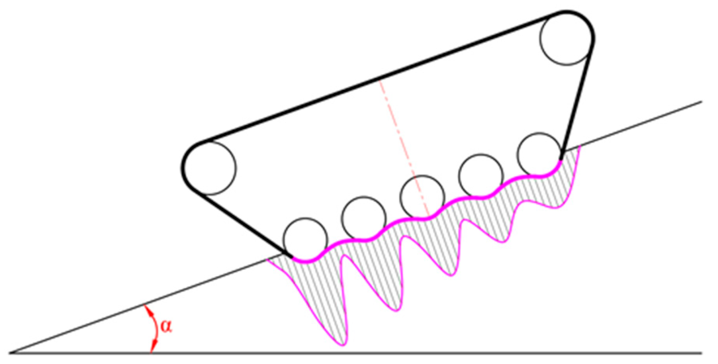
For MCTS with sparsely arranged road wheels, when operating on compliant terrain, the contact pressure distribution exhibits multi-peak nonlinear characteristics. In this scenario, the vehicle’s vertical load is transmitted to the soil through flexible tracks enveloping the road wheels. As illustrated in Figure 6, the tracks undergo dynamic deformation conforming to the road wheel profiles, manifesting local convex protrusions beneath road wheels and concave depressions in inter-roller regions, thereby constituting a continuous wavy deformation pattern with periodic characteristics. The ground contact pressure distribution under the specified conditions is expressed as [27]
p i y p = F i P z b L 1 + 12   e i P y y i L 2 1 + L L + 6   e i P y c o s 2 N π L 2 y i L                         i = 1 , 2                     y i L 2 , L 2
where yi is the longitudinal distance from any point on the track to the geometric center of the track, N represents the number of periods in the cosine-function contact pressure distribution.

2.2.3. Lateral Resistance at the Track–Soil Interface

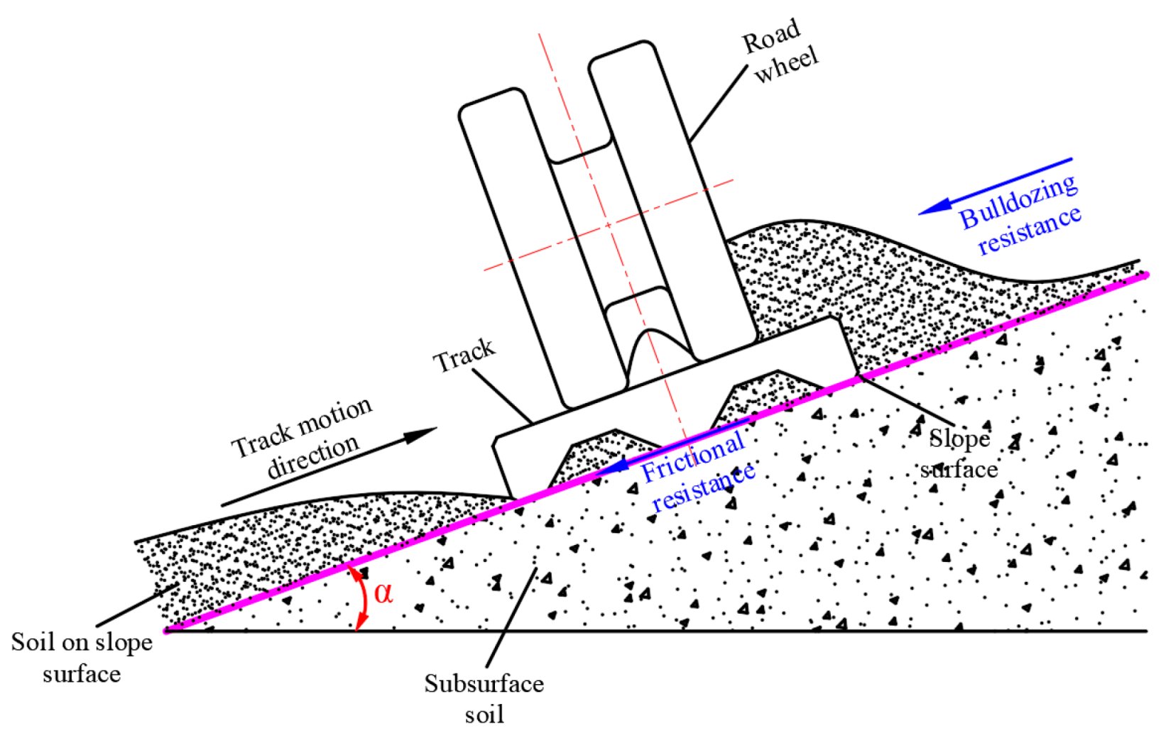
During small-radius turning of mountain crawler tractors on compliant slopes, the track undergoes composite motion at each instantaneous state. Specifically, the track contact segment simultaneously executes translational motion relative to the instantaneous turning center and rotational motion about this center. During translation, the segment experiences longitudinal resistance from the slope surface; during rotation, it is subjected to steering (lateral) resistance opposing its motion direction. As illustrated in Figure 7, this lateral resistance primarily comprises two components: sliding friction between track and soil, and bulldozing resistance generated by the track grousers displacing soil during rotation.
(1)
Frictional Resistance
Based on the lateral force distribution of both tracks during slope steering of MCTs shown in Figure 8, the expressions for the frictional forces F1Px and F2Px along the xp-direction can be derived as follows:
F 1 P x = b 2 b 2 d x 1 L 2 S μ p 1 y p d y 1 b 2 b 2 d x 1 S L 2 μ p 1 y p d y 1 F 2 P x = b 2 b 2 d x 1 L 2 S μ p 2 y p d y 2 b 2 b 2 d x 1 S L 2 μ p 2 y p d y 2
The frictional resistance moments M1Pz and M2Pz are torques about the geometric centers of both tracks, which are mechanically simplified to frictional moments M1Ps and M2Ps about the instantaneous steering center P.
M 1 P s = M 1 P z + F 1 P x S
M 2 P s = M 2 P z + F 2 P x S
(2)
Bulldozing Resistance
During small-radius steering of mountainous crawler tractors on soft slopes, significant vehicle sinkage occurs. The grousers, ribs, and track plates continuously shear and crush the soil, which accumulates laterally beside the track contact section and road wheels. To maintain rotational motion, the track plate end faces, road wheel flanges, and track guide lugs must forcibly rotate this accumulated soil. Consequently, bulldozing resistance is generated, constituting a key factor influencing the slope steering performance of tractors.
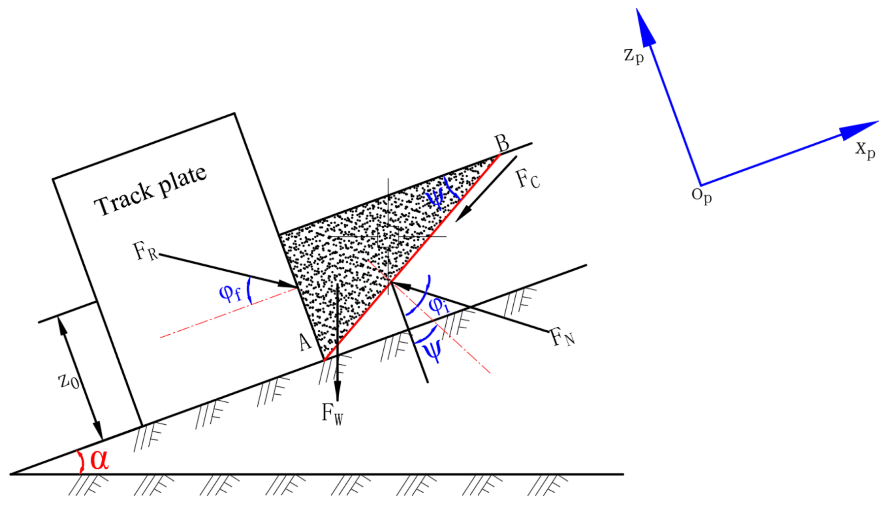
Figure 9 illustrates the bulldozing effect exerted by lateral soil on tracks during slope steering of mountainous crawler tractors. In the diagram
  • Plane AB denotes the soil-track interaction surface;
  • z represents soil sinkage perpendicular to the slope surface;
  • FR is the bulldozing resistance per unit track length;
  • FW denotes the gravity force of the soil wedge above plane AB per unit length;
  • FN indicates the supporting force from soil beneath plane AB;
  • FH signifies sliding resistance on plane AB;
  • φf designates the track plate wall friction angle;
  • φi represents the soil internal friction angle;
  • ψ defines the inclination angle of the soil failure wedge.
Based on Bekker’s pressure–sinkage relationship [28], the sinkage z0i of tracks in soft terrain is given by
z 0 i = p i y p k c b + k ϕ 1 n                               i = 1 , 2
where kc is the cohesive modulus of soil, kϕ is the frictional modulus of soil, and n is the deformation index.
The expression for the gravity force of the soil wedge FW is given by
F W = γ s   z 0 2 c o t ψ 2
where γs denotes the unit weight of soil.
The sliding resistance FH on interaction surface AB is given by
F H = z 0   c s i n ψ
where c denotes the cohesion of soil per unit area.
During steady-state slope steering, the force equilibrium on track plates is maintained at any instant, thus the equilibrium equations are established as follows:
F x p = 0 F R c o s φ f F H c o s ψ F W s i n α F N s i n ψ + φ i = 0
F P z = 0 F R s i n φ f F H s i n ψ F W c o s α + F N c o s ψ + φ i = 0
Solving Equations (44)–(48) simultaneously yields the bulldozing resistance FR exerted by lateral soil per unit track area during slope steering of mountainous crawler tractors:
F R = z 0   c   c o s ψ   c o t ψ + φ i + 1 + 1 2   γ s   z 0 2 c o t ψ c o s α + s i n α   c o t ψ + φ i c o s φ f c o t ψ + φ i s i n φ f
Since exact numerical solutions for bulldozing resistance cannot be directly obtained from Equation (49), it is reformulated as a function of the failure plane angle ψ in the following form:
F R = k k 1 c o t 2 ψ + k k 2 c o t ψ + q q 1 k k 4 c o t ψ + q q 2
where
  • kk1 denotes the coefficient of the cot2ψ term in the numerator, expressed as
1 2 z 0 2   γ s s i n α + z 0 c c o t φ i + 1 2 z 0 2   γ s   c o s α
  • kk2 denotes the coefficient of the cotψ term in the numerator, expressed as
1 2 z 0 2   γ s c o s α   c o t φ i + s i n α
  • qq1 denotes the coefficient of the constant term in the numerator, expressed as
z 0   c   c o t φ i
  • kk4 denotes the coefficient of the cotψ term in the denominator, expressed as
c o s φ f c o t φ i s i n φ f
  • qq2 denotes the coefficient of the constant term in the denominator, expressed as
s i n φ f c o t φ i c o s φ f
Equation (50) reveals that at a given slope angle α, FR is a function of ψ. When FR reaches its minimum value FRmin, it corresponds to a specific ψ value at which soil wedge failure occurs. Under this condition, the bulldozing resistance and resistance moment acting on the tracks attain their maximum values. Differentiating Equation (50) yields
F R = k k 1   k k 4 c o t 2 ψ + 2 c o t ψ   k k 1   q q 2 + k k 2   q q 2 k k 4   q q 1 k k 4 c o s ψ + q q 2 s i n ψ 2
Solve for cotψ when F’R = 0 and the denominator is non-zero.
c o t ψ = k k 1   q q 2 ± k k 1 2   q q 2 2 k k 1   k k 2   k k 4   q q 2 + k k 1   k k 4 2   q q 1 k k 1   k k 4
Considering the engineering significance of the ψ value, select
c o t ψ = k k 1   q q 2 + k k 1 2   q q 2 2 k k 1   k k 2   k k 4   q q 2 + k k 1   k k 4 2   q q 1 k k 1   k k 4
Applying the inverse cotangent function to cotψ yields the ψ value. Substituting this into Equation (49) gives FRmin, from which the bulldozing resistance FTi and resistance moment MTi exerted by lateral soil on tracks during slope steering of mountainous crawler tractors are calculated as follows:
F T i = L 2 S F R m i n c o s φ f   d y S L 2 F R m i n c o s φ f   d y = 2 F R m i n c o s φ f S                                 i = 1 , 2
M T i = L 2 0 F R m i n c o s φ f   y   d y + 0 S F R m i n c o s φ f   y   d y + S L 2 F R m i n c o s φ f   y   d y = F R m i n c o s φ f L 2 4                   i = 1 , 2

2.2.4. Sinkage Resistance of Soft Soils on Tracks

Under general conditions, when mountainous crawler tractors operate on soft slopes, the underlying soft soil experiences sinkage. After calculating the sinkage z0i using Bekker’s pressure–sinkage theory (Equation (44)), the sinkage resistance during small-radius slope steering of mountainous crawler tractors can be determined as follows [27]:
F C i = b n + 1   k c b + k ϕ 1 n p i y p n + 1 n                                           i = 1 , 2

2.3. Numerical Solution and Result Analysis

Substitute the ground contact pressure Formula (40), sliding friction Formula (41), bulldozing resistance Formula (54), bulldozing resistance moment Formula (55), and sinkage resistance Formula (56) into the dynamic Equations (25)–(30). This system constitutes a set of second-order differential equations. Since force and moment terms in all directions implicitly contain unknown motion parameters (inertial forces and moments), and complex coupling exists between parameters, analytical methods cannot yield precise solutions. Computer-aided numerical methods are required for resolution. Substituting Equation (41) into Equation (25) yields an expression for S containing polynomials and trigonometric functions, which cannot be solved symbolically. Numerical methods remain essential for practical computation. Therefore, this study employs the computational software Maple 2024 for numerical solving and case simulations.
A specific model of mountainous crawler tractor was selected for numerical solving and case analysis, with its primary structural parameters listed in Table 1. The relevant soil parameters for sloping terrain, obtained from experimental studies [2], are presented in Table 2.

3. Results

3.1. Effect of Longitudinal Offset of Instantaneous Steering Center on Steering Stability

During small-radius slope steering of MCTs, the position of the instantaneous steering center shifts under the influence of gravitational components. Consequently, the longitudinal offset S of this center varies dynamically. As a critical indicator of vehicle stability during small-radius slope steering, analyzing the variation patterns of S throughout the steering process and investigating the primary factors influencing its positional changes provide a theoretical basis for enhancing the slope steering stability of crawler vehicles.
To facilitate subsequent analysis, supplementary explanations are provided for the longitudinal offset S of the instantaneous steering center:
  • When S = 0, the vehicle’s instantaneous steering center coincides with the theoretical instantaneous steering center, representing an ideal steering condition;
  • When S increases, the instantaneous steering center shifts toward the direction of vehicle motion;
  • When S decreases, the instantaneous steering center shifts opposite to the direction of vehicle motion;
  • The magnitude of S indicates the deviation from the ideal steering condition, where larger |S| signifies greater deviation;
  • When −L/2 ≤ S ≤ L/2, the instantaneous steering center remains within the track contact segment, indicating stable slope steering;
  • When S < −L/2 or S > L/2, the instantaneous steering center deviates beyond the track contact segment, resulting in unstable slope steering with risks of arbitrary sideslip phenomena.

3.1.1. Offset Characteristics of Instantaneous Steering Center Under Varying Slope Angles

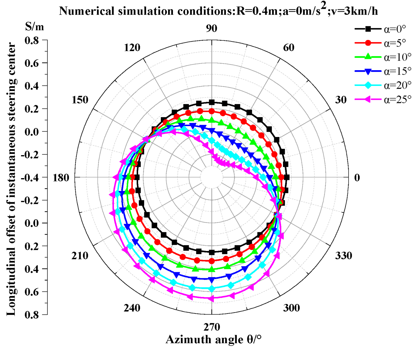
When the crawler tractor operates at a speed of 3 km/h, acceleration of 0 m/s2, and steering radius of 0.4 m, the variation curves of the longitudinal offset S of the instantaneous steering center with azimuth angle θ under slope angles α = 0°, 5°, 10°, 15°, 20°, 25° are shown in Figure 10. Except for α = 0° (level-ground steering), as θ continuously changes, S undergoes three-phase variations across four typical operational scenarios:
1.
Uphill steering on longitudinal slopes (θ ∈ [0°,90°)):
  • S initially decreases then increases;
  • Steering center shifts backward from initial position;
  • Maximum backward displacement (S ≈ −0.25 m) at θ ≈ 60°;
  • Subsequently shifts forward.
2.
Downhill steering on contour-aligned slopes and Downhill steering on longitudinal slopes (θ ∈ [90°,270°)):
  • S monotonically increases;
  • Steering center shifts continuously forward;
  • Coincides with level-steering center at θ ≈ 150° and 330°;
  • Maximum forward displacement (S ≈ 0.67 m) at θ ≈ 270°.
3.
Uphill steering on contour-aligned slopes (θ ∈ [270°,360°)):
  • S monotonically decreases;
  • Steering center shifts continuously backward toward initial position.
Figure 10 demonstrates that slope angle significantly affects the longitudinal offset S of the instantaneous steering center. Increasing slope angle amplifies the absolute value of S, thereby exacerbating deviation from the ideal steering condition. The analysis reveals
  • During uphill steering on longitudinal slopes at slope angles α > 15°, the instantaneous steering center progressively shifts toward the rear of the track contact segment as α increases. Near the azimuth angle θ ≈ 90°, this leads to oversteering conditions characterized by reduced steering radius, analogous to the “nose-in behavior” observed in understeering rear-drive passenger vehicles.
  • During downhill steering on contour-aligned slopes and longitudinal slopes, the instantaneous steering center progressively shifts toward the front of the track contact segment as the slope angle increases. Near the initial position of longitudinal uphill steering (θ ≈ 270°), this leads to understeering conditions characterized by an enlarged steering radius.
  • During uphill steering on contour-aligned slopes, the instantaneous steering center migrates from the front of the track contact segment toward its center as the slope angle increases, while oversteering persistently manifests.
  • Under both downhill steering scenarios, understeering conditions emerge. Influenced by the gravitational component parallel to the slope and the forward-shifted instantaneous steering center, significant lateral sliding occurs at the rear of the track contact segment. This manifests as “tail-swing behavior” analogous to oversteering in rear-wheel-drive vehicles. Slope gradients amplify this phenomenon—greater slope angles intensify tail-swing severity. When lateral forces exceed the crawler tractor’s lateral adhesion capacity, the steering center exits the track contact segment, triggering whole-vehicle sideslip with rearward pendulum motion. In extreme cases, the outer track loses ground contact, precipitating rollover.
Moreover, increased slope angles induce hysteresis in the reversal of instantaneous steering center offset direction, with hysteresis effects intensifying at steeper slopes. Figure 10 demonstrates
1.
For α ≤ 15°:
  • Rearward-to-forward shift reversal occurs at θ ≤ 60°;
  • Forward-to-rearward shift reversal occurs at θ ≤ 250°.
2.
For α > 15°:
  • Rearward-to-forward reversal initiates at θ > 60°;
  • Forward-to-rearward reversal initiates at θ > 250°.
Critical Safety Observation:
At α = 25°, after traversing two downhill steering phases, severe downhill inertial effects drive the steering center toward the front edge of the track contact segment. This position precipitates deteriorating steering stability and elevates accident risks.

3.1.2. Analysis of Factors Influencing Instantaneous Steering Center Offset

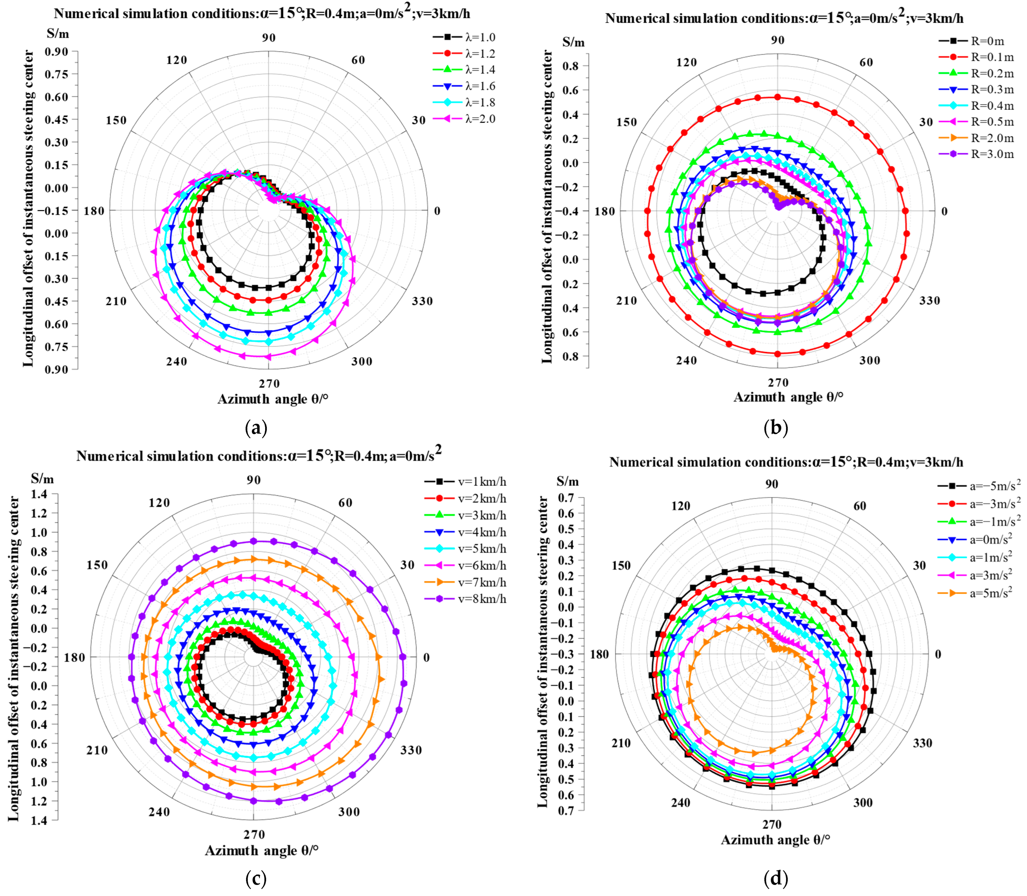
Figure 11a presents the variation curves of the instantaneous steering center longitudinal offset S with azimuth angle θ under different steering ratios λ at a slope angle of 15°, speed of 3 km/h, acceleration of 0 m/s2, and steering radius of 0.4 m. The steering ratio λ = L/B (a structural parameter determining steering agility [29]) exhibits a positive correlation with the absolute value of S, where larger λ values correspond to increased offset magnitudes. Critical structural parameters influencing steering performance include track contact length L and track gauge B:
  • Reducing L diminishes steering center offset, enhancing stability during small-radius slope steering. However, this concurrently elevates ground contact pressure, intensifying soil compaction risks in agricultural fields.
  • Increasing B reduces offset magnitude and augments steering torque capacity, but expands the vehicle footprint, impeding operation in confined hilly terrain.
Consequently, vehicle design requires multi-objective optimization to balance steering stability enhancement against soil preservation and operational maneuverability constraints.
Figure 11b illustrates the variation curves of the instantaneous steering center longitudinal offset S with azimuth angle θ under different steering radii at a slope angle of 15°, speed of 3 km/h, and acceleration of 0 m/s2. Key findings from the S-variation trends are
1.
Radius-dependent fluctuation:
  • Excluding zero-radius steering, larger steering radii increase the range of S (i.e., amplified steering center fluctuation).
2.
Small-radius zone (R < 0.525 m):
  • Decreasing R (excluding R = 0) elevates the average deviation from the ideal steering center.
3.
Critical thresholds:
  • R ≤ 0.3 m: Steering center remains in the front section of the track contact segment, inducing persistent understeering.
  • R = 0.1 m: Steering center approaches or exceeds the front edge of the contact segment, causing severe instability with significant safety hazards.
In contrast, in large-radius steering zones (specifically R = 2 m and R = 3 m), the tractor experiences both oversteering and understeering conditions. When the vehicle travels near the azimuth angles where uphill and downhill operations mutually convert (i.e., θ = 90° and θ = 270°), the instantaneous steering center position reaches maximum rearward and forward offsets, respectively. At this moment, ‘nose-pushing’ and ‘tail-swinging’ phenomena occur, and these phenomena become more pronounced with increasing steering radius. This is because on soft terrain, the steering resistance coefficient decreases as the steering radius increases [5], which further leads to reduction in the steering resistance moment.
Figure 11c demonstrates the variation patterns of the longitudinal offset of the instantaneous steering center with azimuth angle under different vehicle speeds, given a slope angle of 15°, zero acceleration, and a steering radius of 0.4 m. Analysis reveals that higher steering speeds correlate with increased forward displacement of the steering center. Specifically,
1.
Speed–impact relationship:
  • Rising speeds amplify forward steering center displacement.
  • This suppresses “nose-in” behavior while intensifying “tail-swing” phenomena, particularly near the initial contour-uphill steering position (azimuth angle ≈ 270°).
2.
Critical speed thresholds:
  • Above 3 km/h near 90° azimuth:
  • The steering center remains ahead of its ideal position, eliminating oversteering and inducing exclusive understeering (“tail-swing”).
  • Above 6 km/h:
Pronounced centrifugal forces during small-radius steering displace the steering center beyond the track contact segment. This triggers complete “tail-swing” instability, disrupts steady-state steering, and elevates rollover risks.
Under conditions of a 15° slope angle, 0.4 m steering radius, and zero acceleration, Figure 11d reveals the variation patterns of the instantaneous steering center longitudinal offset S with azimuth angle θ under different acceleration levels. Key findings indicate:
1.
Acceleration-dependent dynamics:
  • Transitioning from negative to positive acceleration amplifies fluctuations in steering center offset.
  • Variation patterns remain essentially identical across acceleration levels.
2.
Negative acceleration (a < 0):
  • Steering center oscillates exclusively within the front section of the track contact segment.
  • Oversteering is fully suppressed during all steering phases.
3.
Non-negative acceleration (a ≥ 0):
  • The instantaneous steering center progressively shifts from the rear portion of the track contact segment to the front portion and subsequently moves toward the geometric center of the track system.
  • Severe tail-swing behavior emerges near the downhill endpoint (θ ≈ 270°), demanding critical steering state monitoring.

3.2. Variation Patterns of Tractive Efforts on Dual Tracks

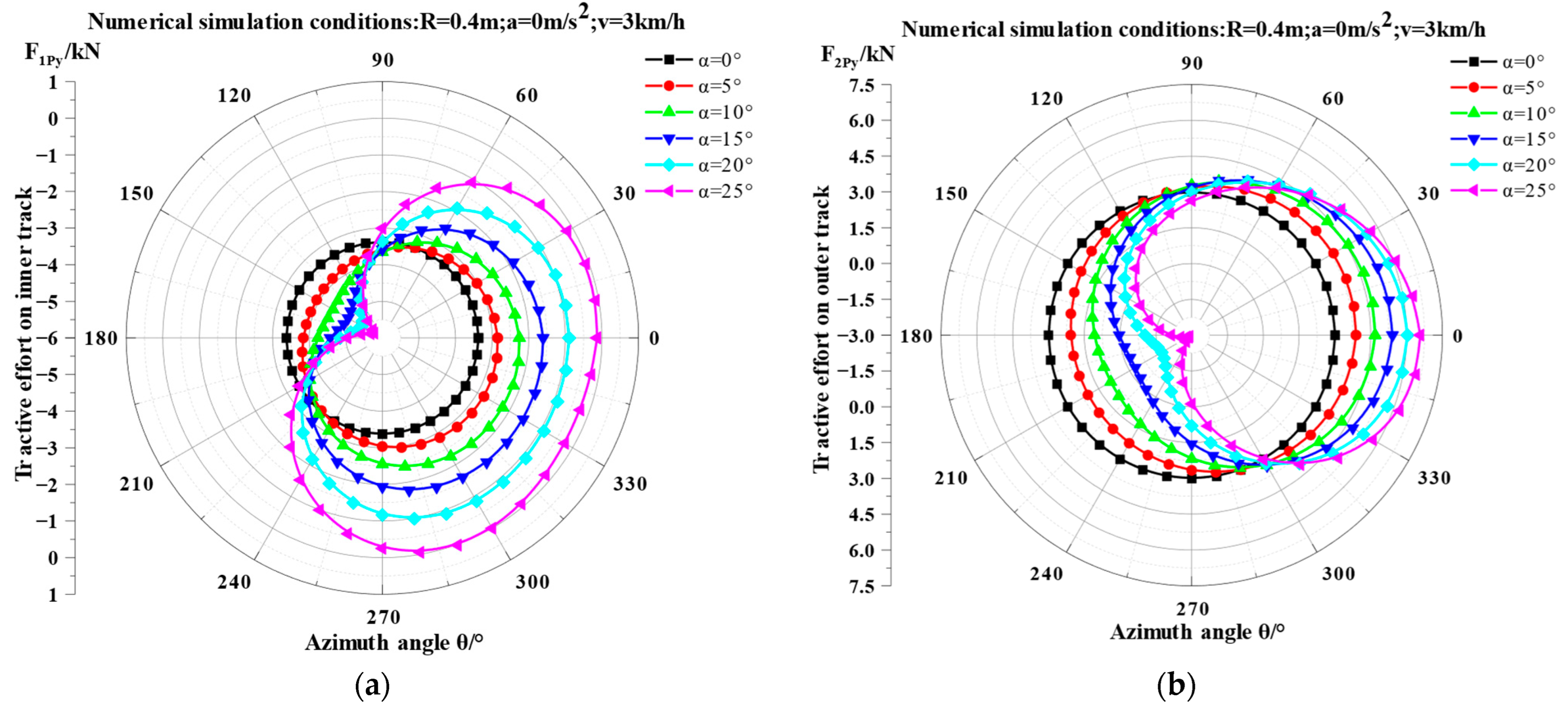
When the crawler tractor speed is 3 km/h, acceleration is 0 m/s2, and radius is 0.4 m, the variation curves of tractive efforts F1py and F2py on inner and outer tracks with azimuth angle θ under different slopes are shown in Figure 12. The tractive efforts on both tracks exhibit certain regular patterns with azimuth angle. To ensure small-radius steering, the inner track delivers braking force in all operating conditions except when the vehicle steers at a 25° slope within θ = [290°, 300°], where minimal tractive effort is required. The outer track primarily delivers tractive effort, transitioning to braking force only under larger slope angles and when the tractor traverses partial azimuth positions during two downhill steering phases.
Within azimuth ranges θ ∈ [0°,90°] and [210°,360°], the required braking force on the inner track decreases with increasing slope angle. Conversely, during downhill steering (θ ∈ [90°,210°]), the inner track braking force requirement increases as slope angle rises. For the outer track,
  • Uphill steering phases (θ ∈ [0°,90°] ∪ [300°,360°)):
  • Required tractive effort increases with slope angle.
  • Downhill-dominated range (θ ∈ [0°,300°]):
Required tractive effort decreases with rising slope angle.
Critical threshold: At α ≥ 15°, appropriate braking force must be applied to counteract gravitational components and centrifugal forces induced by steep slopes.

3.3. Variation Patterns of Bulldozing Resistance on Dual Tracks

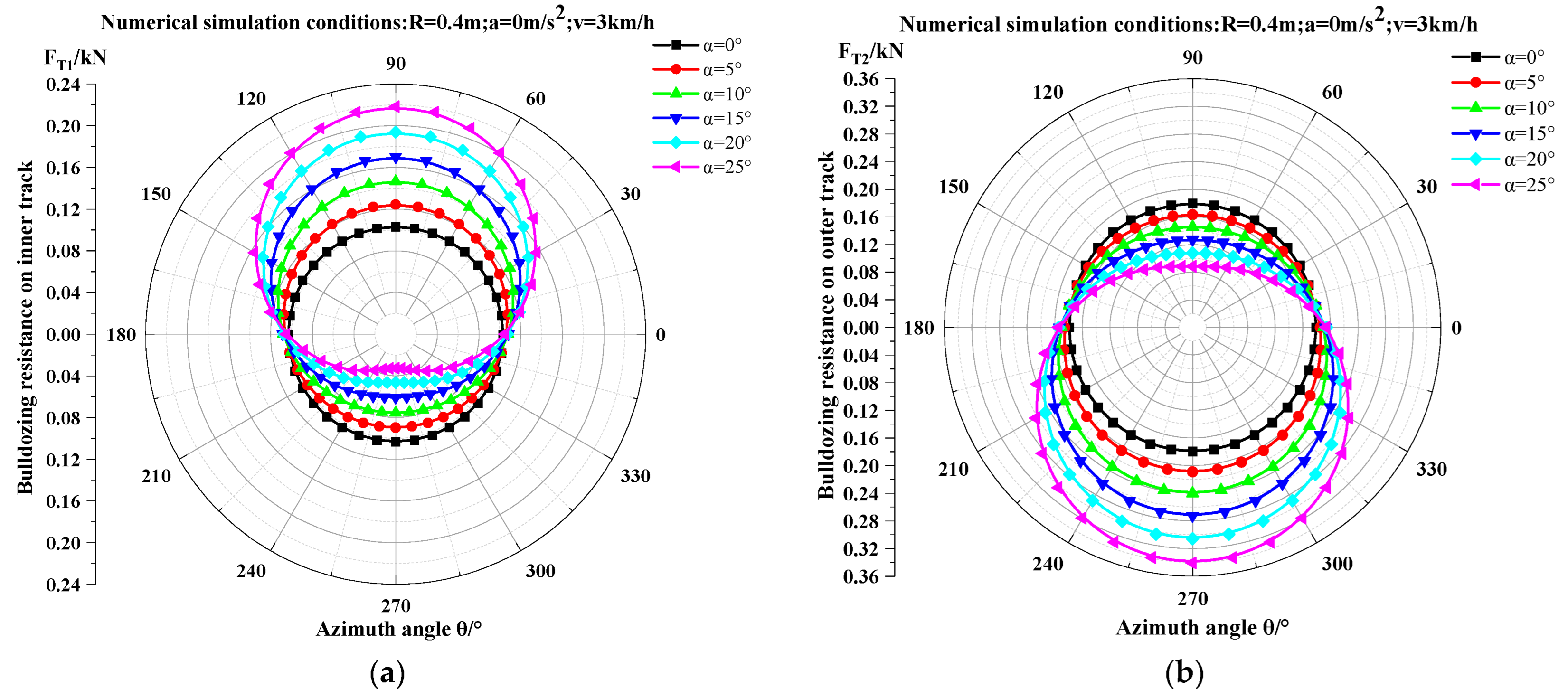
When the mountainous crawler tractor operates at 3 km/h speed, zero acceleration, and 0.4 m steering radius, Figure 13 presents the variation curves of bulldozing resistance FT1 (inner track) and FT2 (outer track) with azimuth angle θ under different slopes. The bulldozing resistance on both tracks evolves through three phases, aligning with trends in mean normal load variations. The primary reason is that—given fixed track width, contact length, and soil parameters—the mean normal load directly determines track sinkage depth, which critically influences bulldozing resistance.
Phase-Specific Dynamics:
1.
Phase 1: Uphill steering on longitudinal slopes (0° ≤ θ < 90°)
  • Inner track resistance increases with rising azimuth angle, reaching its peak at 90°.
  • Outer track resistance decreases with rising azimuth angle, hitting its lowest point at 90°.
2.
Phase 2: Downhill Steering (90° ≤ θ < 270°)
  • Combines contour-aligned and longitudinal downhill steering.
  • Inner track resistance continuously declines, bottoming out at 270°.
  • Outer track resistance rises progressively, peaking at 270°.
3.
Phase 3: Uphill steering on contour-aligned slopes (270° ≤ θ < 360°)
  • Inner track resistance increases as the azimuth angle advances.
  • Outer track resistance decreases as the azimuth angle advances.
Larger slope angles α amplify fluctuations in bulldozing resistance across all three phases for both inner and outer tracks, resulting in higher peaks and lower troughs. Thus, slope angle constitutes a critical factor influencing the steering performance of mountainous crawler tractors.

3.4. Variation in Steering Bulldozing Resistance Moments of Dual Tracks

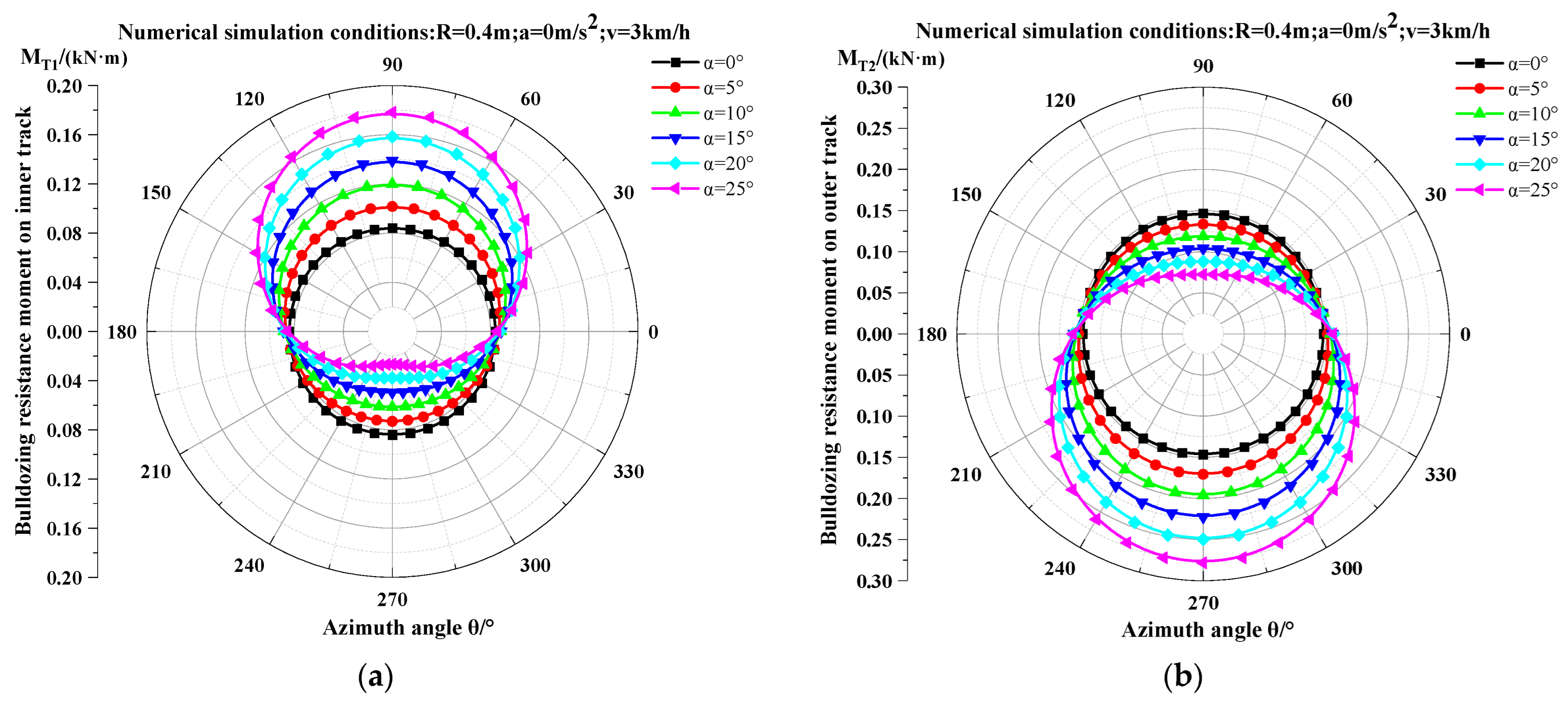
When the crawler tractor operates at 3 km/h speed, zero acceleration, and 0.4 m steering radius, Figure 14 illustrates the variation curves of steering bulldozing resistance moments MT1 (inner track) and MT2 (outer track) with azimuth angle θ. The figure reveals that trends in bulldozing resistance moments align closely with those of bulldozing resistance forces.
Phase-Specific Dynamics:
1.
Uphill steering on longitudinal slopes (0° ≤ θ < 90°)
  • Inner track moment MT1 increases with θ;
  • Outer track moment MT2 decreases with θ.
2.
Downhill Steering (90° ≤ θ < 270°)
  • Inner track moment MT1 decreases with θ;
  • Outer track moment MT2 increases with θ.
3.
Uphill steering on contour-aligned slopes (270° ≤ θ < 360°)
  • Inner track moment MT1 increases with θ;
  • Outer track moment MT2 decreases with θ.
The steering bulldozing resistance moments on inner and outer tracks exhibit identical variation trends to those of the bulldozing resistance forces. This correlation primarily arises because—when vehicle structural parameters and soil properties remain constant—the bulldozing resistance moments are governed by track sinkage depth. Since the mean normal load directly dictates sinkage depth, both parameters consequently demonstrate synchronized variation patterns.

3.5. Experimental Validation and Analysis

To validate the proposed small-radius slope steering model for mountainous crawler tractors, field tests were conducted at the Hilly-Mountainous “Soil-Machine-Crop” Comprehensive Experimental Platform of Northwest A&F University’s College of Mechanical and Electronic Engineering (the Platform specifications detailed in Reference [27]). The test employed a prototype identical to the numerical simulation model (Figure 15), featuring a hydromechanical dual-power flow planetary differential steering mechanism capable of small-radius and spot-turn maneuvers.
Tests occurred on sandy loam roads in China’s Loess Plateau region under soil parameters matching simulation conditions. Given significant centrifugal effects during small-radius steering, vehicle speed was maintained at 1 km/h. Leveraging the platform’s slope simulation capability (0–25°), six gradient conditions (0°, 5°, 10°, 15°, 20°, 25°) were tested with counterclockwise steering while synchronously collecting data.
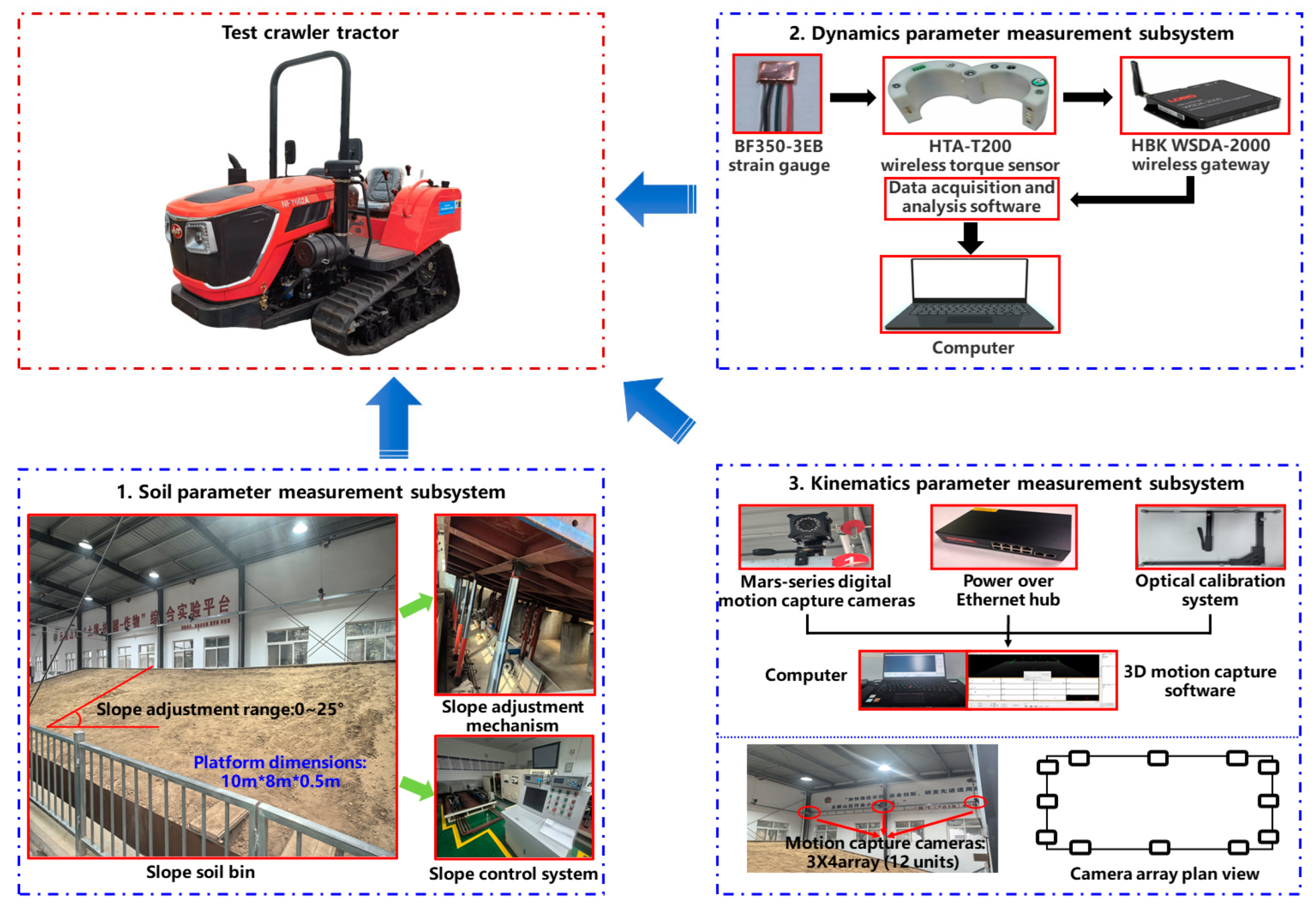
The measurement system (Figure 15) comprised three subsystems:
  • The soil parameter measurement subsystem comprises the comprehensive experimental platform, primarily designed for real-time slope angle measurement.
  • The dynamics parameter measurement subsystem utilizes HTA-200 wireless torque sensors installed on both transmission output half-shafts to indirectly measure the output torque of the drive wheels.
  • The kinematics parameter measurement subsystem was constructed using the NOKOV optical 3D motion capture system from Beijing Measure Technology Co., Ltd. (Beijing, China). It primarily acquires the following parameters during vehicle steering maneuvers: three-dimensional coordinates, azimuth angle, steering trajectory, displacement, linear velocity, linear acceleration, angular velocity, and angular acceleration.
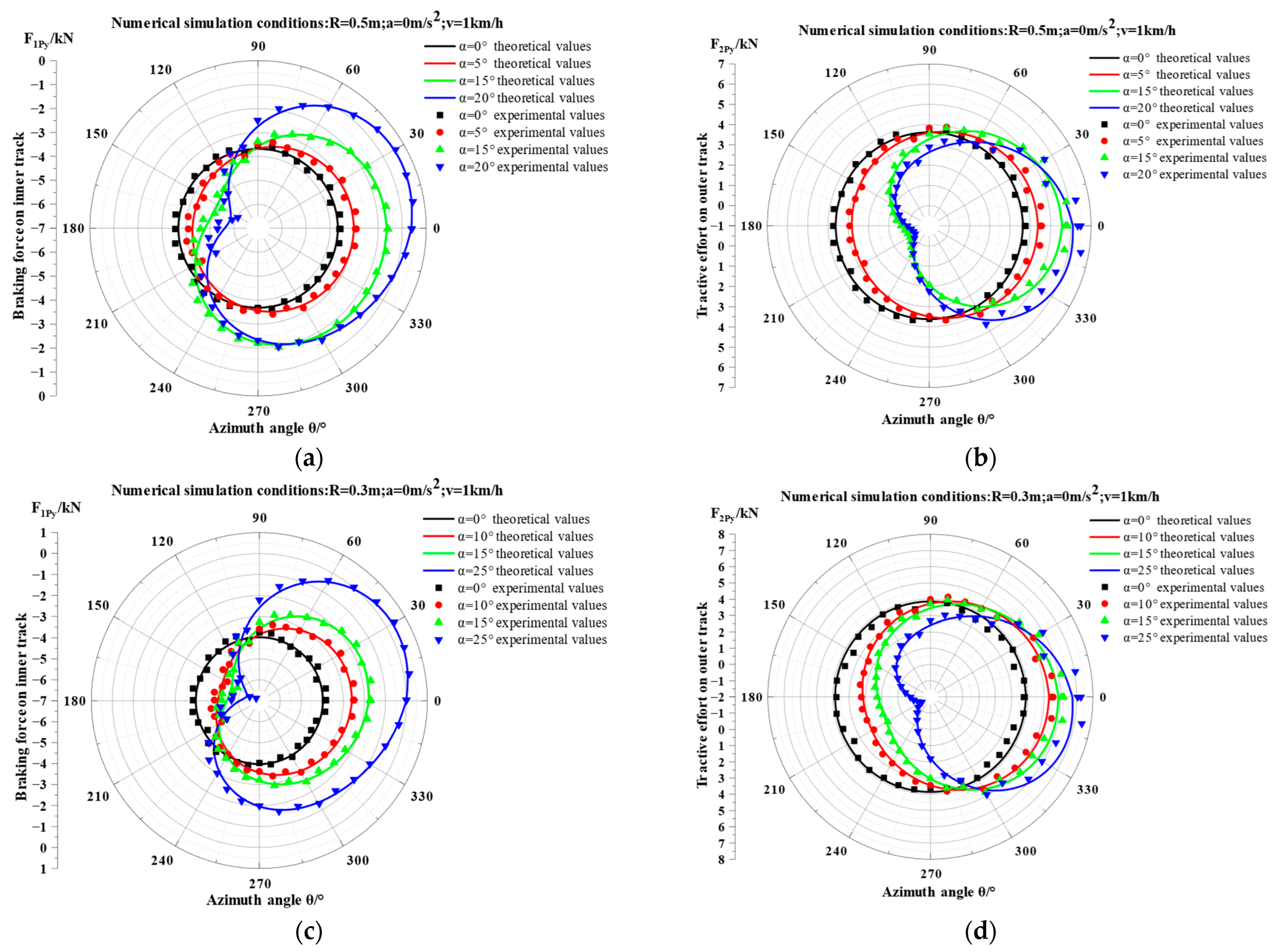
  • The measured torque from the transmission output half-shafts was computationally converted into tractive and braking forces for both inner and outer tracks. Experimental results were compared with theoretical model predictions (Figure 16), with relative errors detailed in Table 3.
Key Findings:
1.
At R = 0.5 m, a = 0 m/s2, v = 1 km/h (Figure 16a,b, Table 3):
  • Outer track tractive effort error: <9.5%;
  • Inner track braking force error: <8.5%;
  • Average tractive effort error (both tracks): <6.5%.
2.
At R = 0.3 m, a = 0 m/s2, v = 1 km/h (Figure 16c,d, Table 3):
  • Outer track tractive effort error: <11.5%;
  • Inner track braking force error: <10.5%;
  • Average tractive effort error (both tracks): <8%.
Validation Conclusion:
Experimental and calculated tractive efforts exhibit consistent variation trends with all relative errors within the 12% acceptable threshold, demonstrating the theoretical model’s high accuracy.

4. Discussion

During operation of mountainous crawler tractors on soft level terrain, the ground contact pressure exhibits non-uniform distribution along the track length. Based on existing theoretical analyses [30,31] and empirical pressure measurements [22,24], the normal load acts directly on the track through road wheels and transfers to the soil, resulting in a periodic cosine-wave pressure distribution. Pressure peaks consistently occur beneath road wheels, with the number of peaks matching the quantity of road wheels, while troughs form between adjacent road wheels.
To characterize this pressure profile, a multi-peak cosine function model with variable amplitudes is adopted. When slope angle effects are considered (with vehicle direction as positive orientation), pressure peaks beneath successive road wheels demonstrate significant gradient variations [21]. Consequently, this study models track contact pressure as an amplitude-varied multi-peak cosine function—yielding better alignment with slope operating conditions than prior research [10,15,19].
This study establishes a small-radius slope steering model for mountainous crawler tractors based on a multi-peak amplitude-varied cosine function for ground contact pressure. It employs position vectors and rotation matrices to represent the pose changes in the tractor’s center of mass in three-dimensional space. By integrating d’Alembert’s principle, the model comprehensively considers factors including slope angle, slip and skid, soil properties, vehicle structural parameters, bulldozing resistance, and sinkage resistance. Results indicate that slope angle is a critical parameter influencing the dynamic characteristics of crawler vehicles during small-radius slope steering, playing a significant role particularly in steering stability, tractive/braking force switching of tracks, and bulldozing resistance variations.
With the widespread application and significant achievements of electric drive technology in the automotive sector, electric drive systems for crawler vehicles have emerged as a new research focus. Electrically driven crawler vehicles can achieve small-radius steering and spot-turn maneuvers through precise control. This study provides a theoretical foundation for developing steering control strategies for such vehicles, as exemplified by dual-motor independently driven crawler systems:
1.
Level-ground small-radius steering [32]:
  • Control outer motor to output tractive effort;
  • Control inner motor to deliver braking force.
2.
Slope small-radius steering:
  • Dynamically regulate motor torque on both sides based on real-time slope angle and azimuth;
  • Critical intervention: During downhill operations on slopes exceeding 15°, the outer motor must apply braking torque to maintain vehicle stability during small-radius steering on steep gradients, thereby preventing severe sideslip or rollover.
To enhance stability and safety during small-radius slope steering of crawler vehicles, the following recommendations are proposed based on this study’s findings:
  • Control strategies should adjust inner/outer track torque distribution dynamically based on real-time slope angle and azimuth. Actively employ outer-track braking on steep slopes to improve steering stability.
  • Strictly limit steering speed to mitigate rollover and tail-swing risks caused by increased centrifugal forces and rapid normal load transfer.
  • Vehicle design should optimize the center-of-mass position [15] and track steering ratio (L/B) to enhance load distribution uniformity during slope steering, simultaneously reduce instantaneous steering center offset, and ensure accurate trajectory tracking.
It should be noted that although this study employs an amplitude-varied multi-peak cosine ground contact pressure model better aligned with practical conditions, discrepancies persist between the steering model and experimental results. These primarily stem from:
  • Idealized soil assumption—Actual soil properties are complex and variable, potentially compromising accuracy;
  • Planar slope simplification—Real terrain exhibits undulations rather than idealized planes;
  • Neglected tension effects—Track tension influence on driving torque was disregarded.
Soil moisture content critically affects soil bearing capacity characteristics [33]. Alterations in bearing capacity impact periodic ground contact pressure distribution, thereby influencing the tractive effort required for crawler vehicle steering.
Future research should investigate coupled effects of soil properties, road surface excitation, and tension variations on steering performance to enhance model predictive accuracy.
In summary, slope angle significantly influences the dynamic response of crawler vehicles during small-radius slope steering by directly altering gravitational components and indirectly modifying ground contact pressure distribution (via normal load/sinkage effects). This manifests most critically in the tractive-to-braking transition of the outer track and its associated dynamic instability risks. These findings provide a theoretical basis for designing crawler tractors better adapted to hilly and mountainous operations. Future research will incorporate multi-factor coupling dynamics and advanced simulations to enhance the practical utility of these outcomes.

5. Conclusions

This study addresses the operational challenges of mountainous crawler tractors in China’s hilly and mountainous regions, where confined slope plots necessitate frequent small-radius slope steering maneuvers. A novel small-radius slope steering model for crawler vehicles, better aligned with actual working conditions, was developed to investigate the steering performance of specific mountainous crawler tractors. Validation was conducted using the distinctive “Soil-Machine-Crop Comprehensive Experimental Platform” for hilly terrain, demonstrating consistency between measured data and theoretical model predictions. The established model provides a theoretical foundation for predicting and evaluating small-radius slope steering performance while enabling stability control. The principal conclusions are summarized as follows:
Under level-ground steering conditions, the position of the instantaneous steering center remains fixed. During slope steering, the instantaneous steering center undergoes periodic changes with the vehicle’s azimuth angle, leading to steering instability. Specifically,
  • Within azimuth angles θ ∈ [0°, 60°], the steering center shifts rearward, reaching its maximum rearward displacement (S = −0.25 m) near θ = 60°, which induces oversteering (“nose-in”).
  • Within azimuth angles θ ∈ [60°, 270°), the steering center shifts forward, achieving its maximum forward displacement (S = 0.67 m) near θ = 270°, resulting in understeering (“tail-swing”).
  • Within azimuth angles θ ∈ [270°, 360°), the steering center shifts rearward and moves toward the initial position.
Increasing slope angles exacerbates the offset distance of the instantaneous steering center while inducing hysteresis in directional shifts in the center. At α = 25°, during downhill phases, downhill inertial momentum drives the steering center toward the front edge of the track contact segment, significantly deteriorating steering stability. When lateral forces exceed adhesion capacity, arbitrary sideslip or even rollover will occur.
Beyond slope angle, variations in steering ratio, steering radius, speed, and acceleration also induce offset of the instantaneous steering center. Crucially,
  • Increased steering ratio causes significant growth in steering center offset distance.
  • Thus, during tractor design, rational selection of track contact length and track gauge is essential to ensure slope steering stability while meeting passability and ground contact pressure requirements.
  • Smaller steering radii amplify fluctuations in steering center offset because reduced radii increase steering resistance coefficients, lateral resistance, and centrifugal forces.
  • High-speed steering intensifies instability during small-radius slope maneuvers while elevating tail-swing and rollover risks. Consequently, travel speed must be appropriately reduced to enhance safety and stability.
Slope angle significantly influences variations in tractive efforts, bulldozing resistance, and bulldozing resistance moments on both inner and outer tracks. During small-radius steering on level ground, mountainous tractors deliver tractive effort via the outer track while generating braking force on the inner track. In contrast, during small-radius slope steering—particularly on steeper gradients—the outer track must apply braking force to counteract the coupling effects of gravitational components and centrifugal forces during descent. Changes in slope angle directly alter the magnitude of gravitational components, thereby affecting the mean normal load on both tracks and soil sinkage depth, ultimately triggering dynamic responses in tractive efforts, bulldozing resistance, and resistance moments of both tracks.

Author Contributions

Conceptualization, F.Y. and Z.L.; methodology, L.D. and Z.L.; software, K.K.; validation, L.D., J.Z. and H.W.; formal analysis, L.Z. and K.K.; investigation, X.M. and Y.J.; data curation, L.Z. and J.Z.; writing—original draft preparation, L.D.; writing—review and editing, F.Y., Z.L. and L.D.; supervision, F.Y. and Z.L.; project administration, F.Y. and Z.L.; funding acquisition, F.Y. and Z.L. All authors have read and agreed to the published version of the manuscript.

Funding

This research was funded by the National Key Research and Development Project (Project No. 2023YFD2000300) and the National Key Research and Development Project (Project No. 2022YFD2001300).

Data Availability Statement

The data underlying this article cannot be shared publicly due to confidentiality obligations under the National Key R&D Program of China. Access may be granted for research purposes upon reasonable request to the corresponding author, subject to approval by the program management authority.

Acknowledgments

We also thank the anonymous reviewers for improving the manuscript with their critical comments and suggestions.

Conflicts of Interest

The authors declare no conflicts of interest.

Appendix A

Appendix A.1

The terms RSP, M1, M2, M3 in Equation (11) can be expressed as
R S P = R 2 h g t a n α   c o s θ + S 2 + h g t a n α   s i n θ 2 + S 2
M 1 = c o s θ 1 cos α   sin θ sin α   sin θ
M 2 = c o s θ s i n θ 0 c o s α s i n θ c o s α s i n θ s i n α s i n α s i n θ s i n α c o s θ c o s α
M 3 = x P C y P C z P C
The terms RSP’, M1′, M2′, in Equation (12) can be expressed as
R S P = R 2 h g t a n α c o s θ + S 2 + h g t a n α s i n θ R 2 h g t a n α c o s θ + S 2 + h g t a n α s i n θ 2 + S 2 h g t a n α c o s θ + S h g t a n α s i n θ R 2 h g t a n α c o s θ + S 2 + h g t a n α c o s θ
M 1 = sin θ cos α cos θ sin α cos θ
M 2 = s i n θ c o s θ 0 c o s α c o s θ c o s α s i n θ 0 s i n α c o s θ s i n α s i n θ 0
The terms RSP″, M1″, M2″, in Equation (13) can be expressed as:
R S P = R 2 h g t a n α c o s θ + S 2 + h g t a n α s i n θ 2 R 2 h g t a n α c o s θ + S 2 + h g t a n α s i n θ 2 + S 2 3 2 h g t a n α c o s θ + S h g t a n α s i n θ R 2 h g t a n α c o s θ + S 2 + h g t a n α c o s θ 2 + h g t a n α c o s θ + S h g t a n α s i n θ R 2 h g t a n α c o s θ + S 2 + h g t a n α c o s θ 2 R 2 h g t a n α c o s θ + S 2 + h g t a n α s i n θ 2 + S 2 + R 2 h g t a n α c o s θ + S 2 + h g t a n α s i n θ R 2 h g t a n α c o s θ + S 2 + h g t a n α s i n θ 2 + S 2 h g t a n α c o s θ + S 2 h g 2 t a n α 2 s i n θ 2 R 2 h g t a n α c o s θ + S 2 3 2 h g 2 t a n α 2 s i n θ 2 R 2 h g t a n α c o s θ + S 2 + h g t a n α c o s θ + S h g t a n α c o s θ R 2 h g t a n α c o s θ + S 2 h g tan α sin θ
M 1 = cos θ cos α sin θ sin α sin θ
M 2 = c o s θ s i n θ 0 c o s α s i n θ c o s α c o s θ 0 s i n α s i n θ s i n α c o s θ 0

References

  1. Liu, Y. Conjecture on Agricultural Machinery in 2024 (VIII): Breakthrough in Mechanization for Hilly and Mountainous Areas [EB/OL]. 2024. Available online: http://www.amic.agri.cn/secondLevelPage/info/5/173379 (accessed on 14 February 2025).
  2. Sun, J.B.; Zeng, L.K.; Ying, J.; Sun, Q.; Zheng, H.; Sun, Q.; Meng, X.Z. Research Status and Prospects of Key Technologies for Agricultural Crawler Chassis. Trans. Chin. Soc. Agric. Mach. 2024, 55, 202–220. [Google Scholar] [CrossRef]
  3. Pan, G.T.; Yang, F.Z.; Sun, J.B.; Liu, Z.J. Analysis and Test of Obstacle Negotiation Performance of Small Hillside Crawler Tractor during Climbing Process. Trans. Chin. Soc. Agric. Mach. 2020, 51, 374–383. [Google Scholar] [CrossRef]
  4. Liu, Q. Research of Manoeuvrability Performance for Mountain Tracked Chassis on Slopes Under Non-linear Ground Pressure. Master’s Thesis, Northwest A&F Universitatis, Yangling, China, 2024. [Google Scholar] [CrossRef]
  5. Hu, J.B.; Li, X.Y.; Wei, C. Driving Principles of Armored Vehicles, 1st ed.; Beijing Institute of Technology Press: Beijing, China, 2020; pp. 140–146. [Google Scholar]
  6. Uberti, S.; Beltrami, D.; Ferrari, M.; Iora, P. Agricultural tractor bogie axle adoption: Market opportunities and traction and ground pressure improvements through mobility metrics and simulations. J. Terramechanics 2025, 117, 101013. [Google Scholar] [CrossRef]
  7. Esch, H.J.; Bashford, L.L.; Von Bargen, K.; Ekstrom, R.E. Tractive performance comparisons between a rubber belt track and a four-wheel-drive tractor. Trans. ASAE 1990, 33, 1109–1115. [Google Scholar] [CrossRef]
  8. Zhang, R.; Zhou, W.; Liu, H.; Gong, J.; Chen, H.; Khajepour, A. Similarities between wheels and tracks: A “tire model” for tracked vehicles. IEEE Trans. Veh. Technol. 2024, 73, 16416–16431. [Google Scholar] [CrossRef]
  9. Zeng, G.; Wang, W.D.; Gai, J.T.; Ma, C.J.; Li, X.M.; Li, H.H. Steering on Ramp Control Strategy of Double Motor Coupling Drive Transmission for Tracked Vehicle. Acta Armamentarii 2021, 42, 2189–2195. [Google Scholar] [CrossRef]
  10. Sun, F.C.; Shi, Q.L. Study on Grounding Pressure of Tracked Vehicles Steering on Ramp. Trans. Chin. Soc. Agric. Mach. 2006, 37, 14–18. [Google Scholar]
  11. Shi, Q.L.; Sun, F.C. Study on Steering Stability of Tracked Vehicles on Ramp. Trans. Chin. Soc. Agric. Mach. 2007, 38, 22–26. [Google Scholar]
  12. Sun, F.C.; Shi, Q.L.; Guo, F.; Zhai, L. Characteristics of Dynamics of Tracked Vehicles Steering on Ramp. Chin. Mech. Eng. 2007, 18, 2766–2771. [Google Scholar]
  13. Zhang, Y.; Qiu, M.; Liu, X.; Li, J.; Song, H.; Zhai, Y.; Hu, H. Research on Characteristics of Tracked Vehicle Steering on Slope. Math. Probl. Eng. 2021, 2021, 1–18. [Google Scholar] [CrossRef]
  14. Wong, J.Y.; Chiang, C.F. A general theory for skid steering of tracked vehicles on firm ground. Automob. Eng. 2001, 215, 343–355. [Google Scholar] [CrossRef]
  15. Dong, C.; Cheng, K.; Hu, K.L.; Hu, W.Q. Dynamic modeling study on the slope steering performance of articulated tracked vehicles. Adv. Mech. Eng. 2017, 9, 1–26. [Google Scholar] [CrossRef]
  16. Jia, X.; Xie, N.; Ding, X.B.; Liu, L.H.; Liu, Y. Establishment and Verification of Steady-State Steering Model for Mountain Tracked Vehicle on Soft Slope Road. J. Agric. Sci. Technol. 2022, 24, 97–111. [Google Scholar] [CrossRef]
  17. Pan, G.T.; Yu, L.F.; Yang, F.Z. Analysis and Simulation on Steering Stability of a Hilly Farmland Information Collection Vehicle on Slopes. J. Agric. Mach. Res. 2015, 37, 6–12. [Google Scholar] [CrossRef]
  18. Luo, H.; Wang, J.D. Kinematic analysis of slope steering on soft ground of tracked vehicle. Agric. Equip. Veh. Eng. 2023, 61, 21–27. [Google Scholar] [CrossRef]
  19. Elsharkawy, A.F.; Kamel, M.A.; Salem, A.M.; Abdelshafy, M.H. Dynamics of Tracked Vehicles during Nonuniform Turning on Level Terrain and on Slopes. Discov. Appl. Sci. 2024, 6, 547. [Google Scholar] [CrossRef]
  20. Zhang, Y.; Liu, X.X.; Chen, H.Q.; Qiu, M.H.; Zhao, Y.; Zhang, X.D. Slope-Steering Motion Planning for Unmanned Tracked Vehicles Based on SSTP-RRT. IEEE Access 2024, 12, 27267–27278. [Google Scholar] [CrossRef]
  21. Yang, F.; Liu, Q.; Ji, Y.; Chu, H.; Duan, L.; Lin, Z.; Shou, Y.; Liu, Z. Development and Validation of Sloped Ground Pressure Pre-diction Model for a Tracked Tractor in Hilly and Mountainous Environments. Soil Tillage Res. 2024, 241, 106135. [Google Scholar] [CrossRef]
  22. Zhao, Z.H.; Mu, X.H.; Guo, H.L.; Lv, K.; Du, F.P. Test and modeling on static ground pressure of rubber track conversion system. Trans. Chin. Soc. Agric. Eng. 2018, 34, 72–79. [Google Scholar] [CrossRef]
  23. Tang, S.; Yuan, S.; Hu, J.; Li, X.; Zhou, J.; Guo, J. Modeling of Steady-State Performance of Skid-Steering for High-Speed Tracked Vehicles. J. Terramechanics 2017, 73, 25–35. [Google Scholar] [CrossRef]
  24. Zhang, R.Z.; Gong, J.W.; Chen, H.Y.; Liu, H.O.; Lu, J.X. Turning Model for Tracked Vehicles on Hard Ground: Analysis and Verification. Acta Armamentarii 2023, 44, 233–246. [Google Scholar] [CrossRef]
  25. Chen, Y.J.; Yi, X.Y.; Yi, C.B.; Liu, S. Strengthening Farmland Quality Improvement to Promote High-Quality Agricultural Development. Chin. Agric. Compr. Dev. 2021, 10, 22–24. [Google Scholar]
  26. Song, H.J.; Gao, L.H.; Cheng, J.W. Research on the Steering of Tracked Vehicles with Zero Turning Radius. J. Acad. Armor. For. Eng. 2007, 21, 55–58. [Google Scholar]
  27. Duan, L.; Kang, K.; Chen, S.; Du, Z.; Zhang, L.; Liu, Z.; Yang, F.; Wang, Z. Analysis and Verification of a Slope Steering Model of TRVs in Hilly and Mountainous Environments. Agronomy 2025, 15, 147. [Google Scholar] [CrossRef]
  28. Bekker, M.G. Introduction to Terrain-Vehicle System, 1st ed.; University of Michigan Press: Ann Arbor, MI, USA, 1969; pp. 4–6. [Google Scholar]
  29. Merhof, W.; Hackbarth, E.M. Terramechanics of Crawler Vehicles, 1st ed.; National Defense Industry Press: Beijing, China, 1989; pp. 65–66. [Google Scholar]
  30. Wong, J.Y. Theory of Ground Vehicles, 5th ed.; John Wiley & Sons, Inc.: Ottawa, Canada, 2022; pp. 139–141. [Google Scholar]
  31. Chen, B.C.; Fan, Y.C.; Ren, L.Q. Relationship Between Track Thrust and Soil Parameters Under Dynamic Variation of Ground Pressure. J. Jilin Univ. (Eng. Technol. Ed.) 1984, 1, 67–84. [Google Scholar] [CrossRef]
  32. Huang, H.; Zhai, L.; Wang, Z. A power coupling system for electric tracked vehicles during high-speed steering with optimization-based torque distribution control. Energies 2018, 11, 1538. [Google Scholar] [CrossRef]
  33. Pang, G.T.; Sun, J.B.; Wang, X.L.; Yang, F.Z.; Liu, Z.J. Construction and experimental verification of sloped terrain soil pressure-sinkage model. Agriculture 2021, 11, 243. [Google Scholar] [CrossRef]
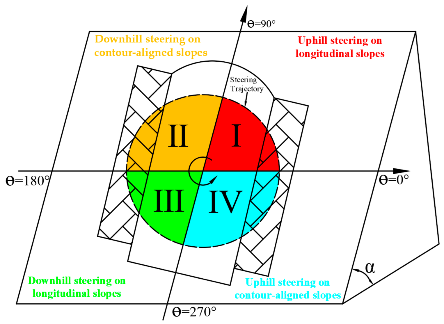
Figure 1. Schematic diagram of the azimuth angle for small radius turning on slopes by a mountain tracked tractor.
Agronomy 15 01956 g001
Figure 2. Schematic diagram of small-radius steering kinematics for MCTs on sloped surfaces.
Agronomy 15 01956 g002
Figure 3. Diagram of motion vector relationships in all coordinate systems.
Agronomy 15 01956 g003
Figure 4. 3D force diagram for small-radius slope steering of mountainous crawler tractors.
Agronomy 15 01956 g004
Figure 5. External force analysis schematic during slope steering of MCTs: (a) external force analysis in the OP-xPzP for MCTs; (b) external force analysis in the OP-xPzP for MCTs.
Agronomy 15 01956 g005
Figure 6. Schematic diagram of contact pressure distribution for MCTs operating on compliant slopes.
Agronomy 15 01956 g006
Figure 7. Lateral resistance acting on the track contact segment during slope steering.
Agronomy 15 01956 g007
Figure 8. Schematic diagram of lateral force distribution on bilateral tracks..
Agronomy 15 01956 g008
Figure 9. Bulldozing effect exerted by lateral soil on tracks.
Agronomy 15 01956 g009
Figure 10. Variation in longitudinal offset of instantaneous steering center under different slope angles at identical conditions.
Agronomy 15 01956 g010
Figure 11. Influence of various factors on longitudinal offset of instantaneous steering center: (a) variation in longitudinal offset S of instantaneous steering center at different steering ratios; (b) variation in longitudinal offset S of instantaneous steering center at different steering radii; (c) variation in longitudinal offset S of instantaneous steering center at different speeds; (d) variation in longitudinal offset S of instantaneous steering center at different accelerations.
Agronomy 15 01956 g011
Figure 12. Variations in tractive efforts of dual tracks under different slope angles at identical conditions: (a) variation in tractive effort F1py on inner track; (b) variation in tractive effort F2py on outer track.
Agronomy 15 01956 g012
Figure 13. Variations in bulldozing resistance of dual tracks under different slope angles at identical conditions: (a) variation in bulldozing resistance FT1 on inner track; (b) variation in bulldozing resistance FT2 on outer track.
Agronomy 15 01956 g013
Figure 14. Variations in bulldozing resistance moments of dual tracks under different slope angles at identical conditions: (a) variation in bulldozing resistance moment MT1 on inner track; (b) variation in bulldozing resistance moment MT2 on outer track.
Agronomy 15 01956 g014
Figure 15. Slope small-radius steering measurement system for MCT.
Agronomy 15 01956 g015
Figure 16. Comparison of theoretical and experimental values for inner and outer track forces: (a) braking force on inner track at R = 0.5 m; (b) tractive effort on outer track at R = 0.5 m; (c) braking force on inner track at R = 0.3 m; (d) tractive effort on outer track at R = 0.3 m.
Agronomy 15 01956 g016
Table 1. Primary structural parameters of MCTs.
Primary Structural ParametersValueUnit
Engine power (P)44.1kw
Engine rated speed (nz)2400r/min
Gross vehicle mass (m)2000kg
Overall dimensions (L×W×H)3400 × 1430 × 2180mm
Track ground contact length (L)1200mm
Track shoe width (b)350mm
Track gauge (B)1080mm
Sprocket pitch radius (r)180mm
Number of road wheels per side (N)5-
Minimum ground clearance (Hd)260mm
Center of mass coordinates (xPC, yPC, zPC)(−20,228,422)mm
Table 2. Soil parameters for sloping terrain.
Soil ParametersValueUnit
Soil moisture content (MC)13.5%/
Cohesive modulus of soil deformation (kc)15.9kN/mn+1
Frictional modulus of soil deformation (kϕ)1179kN/mn+2
Soil deformation index (n)0.597/
Soil cohesion (c)12kPa
Unit weight of soil (γs)1210kg/m3
Soil internal friction angle (φi)20°
Track plate wall friction angle (φf)12°
Table 3. Relative errors between measured and calculated values.
Steering VariablesBraking Force on Inner TrackTractive Effort on Outer Track
Maximum
Relative Error
Mean
Relative Error
R2RMSEMaximum
Relative Error
Mean
Relative Error
R2RMSE
v = 1 km/h, R = 0.5 m, α = 0°4.29%2.8%0.865111.94.75%3.1%0.882122.99
v = 1 km/h, R = 0.5 m, α = 5°5.51%3.6%0.893142.535.97%3.9%0.919155.52
v = 1 km/h, R = 0.5 m, α = 10°5.82%3.8%0.987137.447.05%4.6%0.992177.90
v = 1 km/h, R = 0.5 m, α = 20°8.12%5.3%0.988193.669.34%6.1%0.987246.58
v = 1 km/h, R = 0.3 m, α = 0°4.90%3.2%0.953138.086.28%4.1%0.943129.54
v = 1 km/h, R = 0.3 m, α = 10°5.67%3.7%0.967154.836.89%4.5%0.971191.86
v = 1 km/h, R = 0.3 m, α = 15°7.05%4.6%0.979186.528.12%5.3%0.982226.27
v = 1 km/h, R = 0.3 m, α = 25°10.41%6.8%0.986257.611.49%7.5%0.986326.06
Disclaimer/Publisher’s Note: The statements, opinions and data contained in all publications are solely those of the individual author(s) and contributor(s) and not of MDPI and/or the editor(s). MDPI and/or the editor(s) disclaim responsibility for any injury to people or property resulting from any ideas, methods, instructions or products referred to in the content.