Abstract
Global agriculture is confronting unprecedented pressures from population growth, diminishing arable land, and severe rural labor scarcity, necessitating the advancement of intelligent agricultural equipment. As a core component of precision farming, unmanned agricultural tractors demand highly accurate and robust path tracking control. However, conventional methods often fail to cope with unstructured terrain and dynamic wheel slip under real field conditions. This paper proposes an extended state observer (ESO)-based improved Stanley guidance law, which incorporates real-time sideslip angle observation, adaptive preview-based path curvature compensation, and a sliding mode heading controller. The ESO estimates lateral slip caused by varying soil conditions, while the modified Stanley law utilizes look-ahead path information to proactively adjust the desired heading angle during high-curvature turns. Both co-simulation in Matlab-Carsim and field experiments demonstrate that the proposed method significantly reduces lateral tracking error and overshoot, outperforming classical algorithms such as fuzzy Stanley and sliding mode controller, especially in U-turn scenarios and under low-adhesion conditions.
1. Introduction
Global agriculture is grappling with unprecedented pressures from a surging population, diminishing arable land, and worsening rural labor scarcity, spurring an urgent need for the intelligent upgrading of agricultural production systems [1,2,3]. In this context, unmanned agricultural machinery—an indispensable pillar of precision agriculture—has become a pivotal trend to boost operational efficiency, alleviate labor intensity, and optimize resource utilization, with advancements in LiDAR/machine vision sensing, GNSS precision positioning, and edge computing expediting its shift from lab-based research to large-scale field application [4,5,6,7]. However, path tracking control, the core link bridging pre-planned paths and actual field operations, remains a major bottleneck: the unstructured and dynamic farmland environment (e.g., uneven terrain-induced wheel slip or abrupt changes in physical parameters) severely undermines control stability, while the nonlinear dynamic characteristics of agricultural machinery further increase tracking errors [8,9,10,11]. Additionally, existing control strategies each have their inherent limitations. These factors collectively impede the achievement of high-precision path tracking required for precision farming tasks.
To address the challenges of path tracking in complex field environments, extensive research has been conducted on control algorithms, which can be broadly divided into model-based and geometry-based approaches. Model-based methods, represented by linear quadratic regulator (LQR) and model predictive control (MPC), rely on accurate mathematical descriptions of vehicle dynamics to optimize control inputs. LQR minimizes control costs while effectively minimizing system errors by solving linear quadratic optimal control problems over a defined time horizon. This approach ensures stable system operation with minimal control effort [12,13]. However, LQR operates under the assumption that control inputs are unconstrained and is heavily reliant on precise dynamic models. Consequently, when system parameters, such as tire–soil adhesion, fluctuate or when external disturbances, such as sudden crosswinds, occur, the robustness of LQR significantly degrades, resulting in suboptimal performance during extreme scenarios, such as sharp headland turns [14,15,16]. MPC, by contrast, systematically accounts for control constraints (e.g., steering angle limits) and performs rolling optimization within a receding horizon to obtain optimal solutions, making it suitable for systems with explicit constraints [17,18,19]. Yet, as control performance requirements rise (e.g., higher precision for variable-curvature paths), the increase in model dimensions and constraint complexity significantly amplifies the computational burden of online optimization; this is a critical bottleneck for agricultural tractors with limited onboard computing resources. Even with optimizations (e.g., fuzzy adaptive weight control served as the basis for the improved MPC controller proposed by Wang et al. [20]; Rokonuzzaman et al. developed a switching MPC, which uses a supervision mechanism to switch and select an appropriate vehicle model based on the model’s prediction error and solution time [21]; Zhou et al. used genetic algorithms to calculate the optimal time-domain parameters under real-time driving conditions to achieve adaptive MPC [22].), MPC’s high computational demand remains incompatible with real-time field operations. In addition, the sliding mode controller has received extensive attention due to its inherent insensitivity to disturbances [23,24,25]. Adjustable parameters relevant to the sliding surface and system errors are introduced in the adaptive sliding mode path tracking control method proposed by Yin et al., a design that facilitates the adaptive adjustment of control gain. Simulation results demonstrate the effectiveness of the designed control scheme [26]. Ding et al. designed an output feedback second-order sliding mode path tracking control strategy under the condition that only lateral deviation information is measurable [27]. Zhang et al. presented a path tracking control strategy that combines non-singular fast terminal sliding mode control with a finite-time disturbance observer to ensure rapid convergence of tracking errors and suppression of chattering [28].
In contrast to model-based methods, geometry-based path tracking algorithms simplify vehicle dynamics into planar geometric relationships, which avoids reliance on complex dynamic models and thus exhibits superior real-time performance and ease of implementation—traits particularly well-suited for agricultural tractors operating at low speeds under conditions of high environmental uncertainty. The main representatives of this category include PID control, pure pursuit control, and the Stanley guidance law (SGL). PID control is widely adopted for its simplicity, as it does not require precise models and allows for easy deployment; however, it suffers from cumbersome parameter tuning and high sensitivity to external disturbances. Even when combined with intelligent algorithms (e.g., Han et al. utilize the self-learning ability of neural networks to adjust the control gains of the PID path-tracking controller [29], and Marino et al. integrate PID with visual navigation for high-curvature paths [30]), its reactive error compensation logic fails to proactively counteract field disturbances, such as uneven ridges. Pure pursuit control, which is based on vehicle planar geometry, determines the desired steering angle by selecting a look-ahead distance that fits the reference path [31,32]. While improvements, such as fuzzy dynamic adjustment of the look-ahead distance [33,34,35], have enhanced its robustness on variable-curvature roads, it remains overly dependent on the optimal look-ahead distance. This limitation confines its application to low-speed, smooth-road conditions, making it unsuitable for high-curvature headland turns that are common in agricultural operations. SGL, first implemented in Stanford University’s unmanned vehicle for the DARPA Urban Challenge, distinguishes itself among geometry-based methods due to its superior performance [36]. Unlike PID controllers, it employs a nonlinear front-wheel steering angle feedback control law that ensures both lateral and heading errors converge to zero, effectively eliminating steady-state errors. In comparison to pure pursuit control, SGL demonstrates enhanced adaptability at higher speeds, maintaining stable tracking even at the upper operational speeds of agricultural tractors. Researchers have further improved its versatility; for instance, Wang et al. dynamically adjust the control gain of the Stanley controller through the particle swarm optimization algorithm [37]. Cui et al. and Sun et al. established a fuzzy rule base with navigation deviation as input and dynamically adjusted the control gain of the Stanley controller according to the deviation amount [38,39].
However, conventional path tracking controllers exhibit significant limitations when applied to unstructured agricultural field operations. First, they lack effective compensation for time-varying sideslip angles. Field conditions such as loose soil or moisture can lead to considerable tire sideslip, resulting in discrepancies between the actual travel direction and the vehicle’s longitudinal axis. Without real-time observation of sideslip, tracking errors can accumulate rapidly. Second, these algorithms follow an “error-first, compensation-later” logic, where most improvements only adjust parameters after errors have occurred. During high-curvature maneuvers (e.g., tractor headland U-turns), this reactive approach can lead to understeering, as the algorithm is unable to proactively utilize future path information to pre-adjust the desired heading angle. Once errors occur, even saturated steering inputs may fail to reduce the errors to acceptable levels.
To address these limitations, this study proposes an extended state observer (ESO) based improved Stanley guidance law (EISGL) for agricultural tractor path tracking. The main contributions and innovations of this work are summarized as follows:
- (1)
- Real-time sideslip observation and compensation: An ESO is designed to estimate the lateral slip angle in real time, effectively addressing model uncertainties and variations in tire–soil adhesion caused by unstructured field environments.
- (2)
- Look-ahead path curvature pre-compensation: An improved SGL is proposed, which incorporates a weighted error term based on previewed path points. This enhancement enables proactive adjustment of the desired heading angle during high-curvature turns, significantly mitigating understeering behavior typical of conventional Stanley methods.
- (3)
- Integrated robust control architecture: A sliding mode controller (SMC) is employed for heading tracking, offering strong robustness against disturbances and model variations. The synergistic integration of ESO, improved SGL, and SMC forms a composite control strategy that ensures high-precision path tracking under diverse and varying soil conditions, as validated through both simulation and field experiments.
2. Materials and Methods
2.1. System Overview and Modeling
As illustrated in Figure 1, the proposed universal autonomous control system for agricultural unmanned machinery integrates multi-source perception, intelligent decision-making, and collaborative control to form a closed loop system for autonomous operations. The perception layer comprises RTK-GNSS for centimeter level positioning, visual cameras for scene recognition, and LiDAR for 3D environmental sensing, thus enabling comprehensive environmental awareness. The decision-making layer achieves path planning according to field tasks and remote interaction via 5G/4G. The generated optimal trajectories are then transmitted to the control layer. The control layer adopts a dual-controller architecture: the driving controller, integrated with path-tracking algorithms, adjusts the tractor’s motion (including throttle, clutch, and steering) through interactions with sensors and actuators; the operating controller manages implement operations (e.g., lifting, PTO, and hydraulic valves). Both controllers communicate via the CAN bus and cooperate with the electric steering system, ECU, and VCU for power and vehicle management. This platform facilitates autonomous, precise, and intelligent agricultural operations, reducing labor dependence and improving resource utilization, and lays a technical foundation for smart farming.
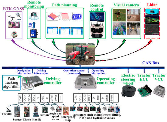
Figure 1.
Structure of universal autonomous control system for agricultural tractor.
In this study, the YTO LY1104 tractor is selected as the experimental platform, with some of its parameters presented in Table 1. The tractor underwent modifications in electrical control, upon which a universal autonomous control system is installed. The standardized interfaces of its CAN-based control system facilitate seamless integration with autonomous modules, including navigation, perception, and remote monitoring.

Table 1.
Description of some parameters of YTO LY1104 tractor.
As illustrated in Figure 2, a 2-degree-of-freedom (2-DOF) planar dynamics model was established to accurately describe the lateral and yaw motion characteristics of the agricultural tractor during path tracking, particularly under field conditions with sideslip interference. This model emphasizes the key motion states that dominate path-following performance while simplifying high-order nonlinear factors that minimally impact lateral control.
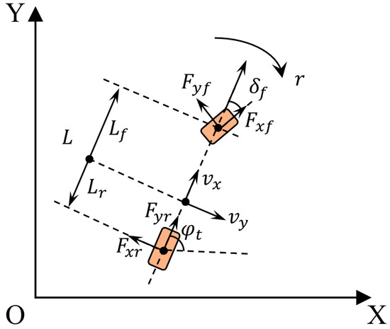
Figure 2.
2-DOF dynamic model of agricultural tractors.
This approach effectively balances model accuracy with computational efficiency for real-time control applications. It is developed based on the following reasonable assumptions, consistent with typical vehicle dynamics modeling practices in path tracking research:
- (1)
- The tractor moves in a horizontal plane, and vertical motion (e.g., pitch, roll) is neglected, as field terrain undulations in this study are within the range that does not significantly affect lateral stability;
- (2)
- Tire behavior follows the linear tire model (Pacejka’s first-order approximation). For small lateral slip angles, which is the common range for agricultural tractors during steady path tracking, the lateral tire force is linearly proportional to the slip angle, avoiding the complexity of high-order nonlinear tire models;
- (3)
- The tractor’s mass and moment of inertia are uniformly distributed, and the influence of auxiliary implements (e.g., plows, seeders) is incorporated into the total mass and yaw moment of inertia;
- (4)
- Aerodynamic forces are neglected, as the operating speed of agricultural tractors (typically ) is much lower than that of road vehicles, making aerodynamic interference negligible.
Based on Newton’s second law of motion and the law of conservation of angular momentum, the dynamics equations of the 2-DOF model are derived as follows [40]:
where is the longitudinal velocity, is the lateral velocity, is the yaw rate, is the front wheel steering angle, and are the lateral force and longitudinal force exerted on the front wheels, respectively, is the lateral force exerted on the rear tires, and are the distance from the center of mass to the front axle and rear axle, respectively, is the moment of inertia of the z-axis, is the total mass of the tractor.
Based on the assumptions mentioned earlier, the state space equation of the tractor dynamics model can be derived as follows:
where and are the cornering stiffness of the front wheels and the rear wheels, respectively.
2.2. Path Tracking Controller Design
The proposed path following control framework integrates an improved SGL, an ESO, and a SMC strategy for heading tracking. As depicted in Figure 3, the navigation and path planning system sends the error states between the tractor and the current path index point as well as the look-ahead path index points to the path tracking controller. The ESO first estimates the tractor’s sideslip angle to compensate for uncertainties in lateral dynamics. Then, the ISGL calculates the desired heading angle by fusing reference path information and the observed sideslip angle. Subsequently, the heading SMC designs an integral type sliding surface, generating the front wheel steering angle to enforce the actual heading angle to track .

Figure 3.
Block diagram of path tracking controller.
2.2.1. Improved Stanley Guidance Law
When the tractor is operating in the field, disregarding its pitch and roll movements, its motion model can be described in the following form [9]:
where is the position coordinates of the tractor, and is the heading angle in the earth-fixed coordinate system of the tractor.
As illustrated in Figure 4, point , , …, are several discrete path index points. Among them, point is the index point closest to the positioning center of the tractor. The traditional SGL calculates the target heading angle of a vehicle based on the nonlinear feedback function of both the lateral error between the vehicle’s position and the closest point on the reference path, as well as the traveling speed, combined with the heading error. Since the variation in the desired yaw angle is primarily determined by the arctangent function and highly consistent with the variation trend of the desired steering angle , in engineering applications, it is often simplified such that can be approximately used as the front wheel steering angle command [39]:
where is the lateral tracking error, is the control gain, is the desired speed, and is the difference between the tractor’s heading angle and the tangential angle of the reference path point. If is a given path and is target point, the specific expression of at the reference path point is as follows:
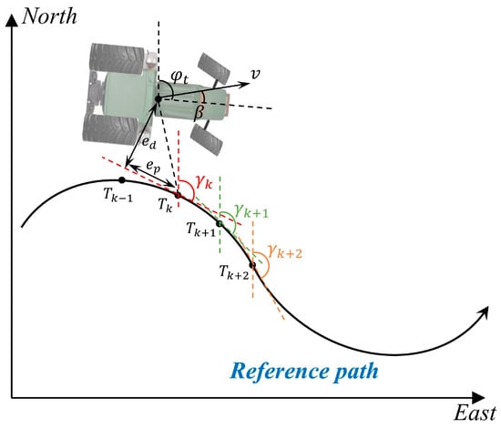
Figure 4.
Schematic of tractor path tracking problem.
The SGL was originally designed to provide a concise path tracking solution for autonomous vehicles, hence featuring only one adjustable control gain . However, determining the optimal fixed value of k under complex working conditions remains challenging. Consequently, most existing improvements to SGL in research literature focus on real-time optimization of via intelligent optimization algorithms. Fundamentally, this follows the logic of “error first, compensation later.” When the tractor operates in the field and encounters large-curvature turning paths, once a path tracking error occurs, it is highly likely that even saturation of the front wheel steering actuator will fail to converge the error to a small value. Therefore, when the tractor tracks large-curvature paths, the desired heading angle should be pre-adjusted to compensate for the SGL.
Based on the aforementioned motivations and theoretical analyses, during the reference path indexing process, we do not merely consider the path point closest to the agricultural tractor; instead, we incorporate the n subsequent points ahead of this closest point into consideration simultaneously. Specifically, the implementation method is: The currently closest indexed path point to the tractor is denoted as , and the path points ahead along the traveling direction are , , …, . The average tangential angle deviation considering these look-ahead path points is defined as:
The improved SGL proposed in this paper is given by:
wherein , are tunable control gains. An inverse proportional nonlinear term of the lateral error is introduced before the average tangential angle , which serves to adjust the weight of the average tangential angle. Specifically, when the absolute value of the tractor’s lateral error is large, this term reduces the weight of the average tangential angle to prevent excessive adjustment caused by the latter; conversely, when the absolute value of the lateral error is small, it increases the weight of the average tangential angle. As illustrated in Figure 4, compared with the traditional SGL, the improved version incorporates an additional nonlinear steering angle term. This term is designed to reflect the curvature state of the future path, thereby realizing pre-compensation for the desired heading angle during curved path tracking.
Next, the convergence of the improved SGL will be proven. For convenience, let , , . It can be derived from Equation (7) and the vehicle kinematic equations that:
When is a minimum value and , , , , it yields that:
It can be known from Equation (10) that the lateral error converges exponentially to zero over time.
2.2.2. Sideslip Compensation
During field operations, tractors often encounter unstructured working conditions such as loose soil, uneven ridges, and local slope variations. The adhesion between the tires and the soil can fluctuate due to factors such as moisture and compaction, leading to significant side slip of either the front or rear wheels. This results in a deviation between the actual travel direction of the tractor and the longitudinal axis of the tractor (i.e., the orientation of the tractor). This deviation is quantitatively characterized by the side slip angle. Therefore, it is necessary to design a method for observing the side slip angle and incorporate the side slip angle compensation into the guidance law:
Based on the error dynamics of agricultural tractor path tracking and combined with the vehicle kinematics equations, it can be obtained that:
where and are the along-track longitudinal error and lateral error between the tractor and the waypoint, respectively, is the tractor’s sideslip angle, and is the speed of the desired point , which can be regarded as the virtual control input of .
Assuming that the sideslip angle is very small and has an upper bound, it can be approximately considered that , . Then, Equation (11) can be rewritten as:
where . Design a reduced-order ESO as follows:
where is the estimated value of , is an auxiliary intermediate variable, is the observer gain. It is easy to obtain by combining Equations (12) and (13):
Define the estimation error as . Assume that the rate of change in the sideslip angle is limited, i.e., . Construct a Lyapunov function:
Differentiating the above equation gives:
where . It yields that:
Therefore, it can be concluded that:
To further prove the stability of the observer, the following two lemmas are introduced.
Lemma 1.
[41] For system , where is a continuously differentiable function in an n-dimensional Euclidean geometric space, if there exist a function of class and a function of class , then for any bounded input
and initial condition , the following inequality holds:
Lemma 2.
[42] Suppose that for the given system , there exists a smooth and continuous function that satisfies the conditions for all and :
where and are functions of class , and and are functions of class . When , the system is input-to-state stable (ISS).
Based on Lemmas 1 and 2, by choosing , there exist class function and class function such that . When , the system g = 1 is ISS. From this, it can be proven that the designed sideslip angle observer can stably estimate the unknown sideslip angle.
To offset the time-varying sideslip angle, the novel guidance law is formulated as:
2.2.3. Heading Tracking Control Based on Sliding Mode
During the tractor’s path tracking process, the desired heading angle is obtained using the guidance law in Equation (22). The design of the heading control algorithm is not the focus of this paper, a relatively simple PID algorithm can be adopted to achieve the tracking objective; however, the PID algorithm is relatively sensitive to parameter tuning and lacks robustness against disturbances under unstructured field conditions. Thus, in this section, an adaptive fuzzy sliding mode controller is employed to realize the tractor’s tracking control of the desired heading angle, thereby achieving the tracking control of the desired path. The part involving parameter identification of the dynamic model refers to the paper [43].
Based on the relationship between the heading angle and the heading angular rate, this study focuses exclusively on the lateral and yaw motions of the tractor. By integrating these considerations with the dynamic model of the tractor, the following state equation can be derived:
where . It can be derived from the above equation:
Based on the principle of linearized feedback control, the control law for the tractor is:
where , are control gains.
Due to the particularity of path tracking in a paddy field environment, the front-wheel control law shown in Equation (25) is difficult to meet the requirements of robustness and adaptability. By introducing the fuzzy sliding mode control theory, based on the universal approximation property of the fuzzy system, there exists an optimal fuzzy control system such that the control law of the front-wheel steering angle is:
where is the parameter vector, is the fuzzy vector, is the fuzzy approximation error and . In addition, , and is the weight of the fuzzy rule.
The sliding mode surface is defined as follows:
The design of the adaptive fuzzy sliding mode control law for the is as follows:
where and are the estimated values of and respectively, and and are positive constants.
Construct the following Lyapunov function:
where and are estimated errors. Differentiating the above equation gives:
When , ; when , ; when , .
To sum up, . Therefore, the adaptive fuzzy control law proposed in this paper is stable.
2.3. Data Flow and Processing in Practical Implementation
To ensure the practical deployment and reproducibility of the proposed path-tracking algorithm, a well-defined data processing pipeline is established, with the core algorithm residing on the STM32F407 driving controller. Real-time data is primarily sourced from an RTK-GNSS receiver at 10 Hz, which provides the tractor’s coordinates and heading angle in a local reference frame after coordinate transformation. Key vehicle dynamic states, including the longitudinal velocity and the yaw rate , are acquired directly from the vehicle’s CAN bus network. These data streams are synchronized within the driving controller and processed at a fixed control frequency of 10 Hz.
During each control cycle, the algorithm executes three sequential steps. First, the ESO estimates the vehicle’s sideslip angle , an unmeasured state critical for accounting for tire-ground interaction slip. The ESO utilizes the current lateral tracking error —the perpendicular distance from the vehicle’s current position to the target point on the reference path—and the heading error . Subsequently, the improved Stanley guidance law calculates the desired heading angle . It synthesizes multiple inputs: the lateral error , the heading error , an average tangential angle deviation computed from a sequence of look-ahead path points to proactively compensate for upcoming path curvature, and the estimated sideslip angle from the ESO. These are processed through the nonlinear function given in Equation (22). Finally, the SMC for heading tracking generates the final steering command. It computes the error between the actual and desired heading angles and its derivative. Based on an integral-type sliding surface , defined in Equation (27), and employing the adaptive fuzzy control law from Equation (28), the SMC produces a robust front wheel steering angle command . This command is constrained by the physical steering limits (±40°) before being issued via the CAN bus to the electric power steering actuator, thereby closing the control loop. All relevant sensor data, intermediate variables, and control commands are logged by the driving controller, ensuring full transparency and facilitating replication of the study.
3. Results and Discussions
In this section, we verify the effectiveness and superiority of the designed path tracking control algorithm through simulations and field experiments. When selecting the algorithm control groups, we chose the following three path tracking algorithms:
- (1)
- Fuzzy Stanley guidance law (FSGL) [39]: The algorithm, based on the traditional SGL described in Equation (4), dynamically adjusts the time-varying gain coefficient according to different lateral deviations through fuzzy rules.
- (2)
- SMC [24]: The sliding mode surface is set as where is the control gain. The reaching law selects the commonly used exponential reaching law.
- (3)
- EISGL in this paper.
To ensure a fair and rigorous comparison among the three controllers, their respective control gains were meticulously tuned prior to the formal experiments. The tuning objective was to minimize the integral of the absolute lateral error (IAE) for each controller independently when tracking a standard validation path. This process, which involved numerous iterative trials for each algorithm, ensured that none were disadvantaged by suboptimal parameters. Consequently, the performance differences observed in the results can be confidently attributed to the inherent strengths of the control architectures themselves, rather than to an uneven parameter tuning process.
3.1. Co-Simulation
Experiments are conducted using a co-simulation of Matlab and Carsim, where all parameters in the simulation were set according to the actual parameters of the tractor. The starting point of the reference path for the simulation is the coordinate origin, consisting of three 30 m long straight lines and two 5 m radius semicircular arcs. The starting point of the tractor is set at (0 m, −0.5 m), meaning the initial lateral deviation is 0.5 m and the initial heading deviation is 0 rad. The running speed of the vehicle’s rear wheels is 1 m/s, the simulation duration is set to 165 s, and the simulation step is 0.01 s.
Since sideslip of the tractor is inevitably observed during operation in slippery field conditions, to simulate real-world operating scenarios, we incorporate the sideslip angle into the simulation—specifically, the sideslip angle is set to 0.08 rad in straight path segments and 0.12 rad in curved path segments.
Figure 5 shows the tracking trajectories of three path-tracking controllers. Figure 6 presents the lateral errors of the three controllers. Figure 7 displays the observed values of the actual sideslip angle by the sideslip observer designed in this paper. A comprehensive analysis of the results presented in Figure 5, Figure 6 and Figure 7 clearly demonstrates that the EISGL controller achieves a significant performance improvement, exhibiting superior overall performance, particularly after the incorporation of sideslip angle observation and compensation. Statistics of the lateral errors for simulation experiments are shown in Table 2.
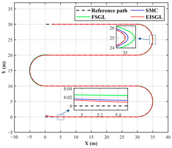
Figure 5.
The tracking trajectories of different controllers in the simulation.
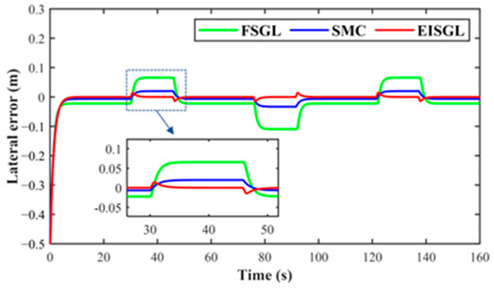
Figure 6.
The lateral errors of different controllers in the simulation.
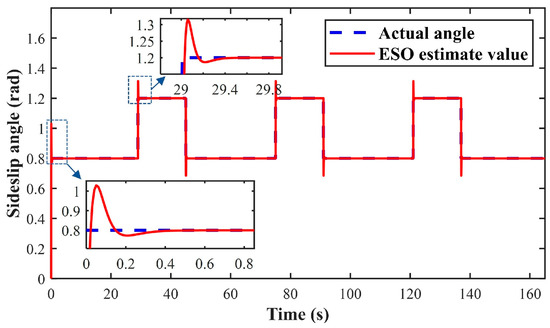
Figure 7.
The observed value of the sideslip angle in the simulation.

Table 2.
Statistics of the lateral errors for simulation experiments.
As shown in Figure 5, the trajectory of the FSGL controller shows the largest deviation, especially on curved sections, where its path curvature is noticeably smaller than that of the reference path. This indicates understeering behavior and an inability to effectively track higher curvature changes. The SMC exhibits improved tracking performance, adhering more closely to the reference path for most of the route. However, noticeable adjustments with trajectory fluctuations remain visible at the entry and exit of curves. In contrast, the EISGL controller demonstrates the highest agreement with the reference path. Its trajectory almost coincides with the reference under both high-curvature turns and straight-line conditions, indicating a stronger adaptability to vehicle dynamics and a more precise generation of control commands for path-tracking tasks.
The differences in tracking trajectories are directly reflected in the lateral error data illustrated in Figure 6. The FSGL controller yields the largest lateral error, which peaks at the initiation of curves, accompanied by slow error convergence and considerable steady-state error. Leveraging its sliding mode variable structure characteristics, the SMC enhances system robustness significantly, resulting in a notably reduced maximum overshoot and faster error convergence compared to the FSGL controller. The EISGL controller stands out with the most outstanding performance, maintaining lateral error within a minimal range throughout the entire process. This is due to the pre-compensation of EISGL for the forward-looking path index points during large-curvature turns. It is particularly noteworthy that the overshoot is nearly eliminated and the steady-state error is minimized. Moreover, the error curve of the EISGL controller transitions smoothly and rapidly when entering and exiting curves, without noticeable oscillations. This confirms that sideslip angle compensation effectively enhances system damping, suppresses overshoot, and thereby achieves smooth, stable, and accurate tracking.
In addition to the look-ahead compensation for the curvature change in the index point, the excellent performance of the EISGL controller can be attributed to another key state—the effective observation and compensation of the sideslip angle. Figure 7 displays the output of the sideslip angle observer designed in this study, which captures the actual sideslip angle generated by the vehicle. It can be observed that the estimated error of the sideslip angle remains close to zero during straight-line driving, while rapidly varying sideslip angles during cornering are also promptly estimated. Since both the FSGL and SMC lack awareness and compensation for this state, and their control laws are based on an ideal vehicle dynamic model, their performance degrades in the presence of sideslip. In contrast, the EISGL controller fully utilizes the sideslip angle observation provided in Figure 8, integrating it as a feedforward compensation term into the control law. This enables the controller to anticipate and counteract the adverse effects of sideslip in advance, explaining why the EISGL controller achieves a smoother trajectory, smaller overshoot, and higher steady-state accuracy in Figure 5 and Figure 6.
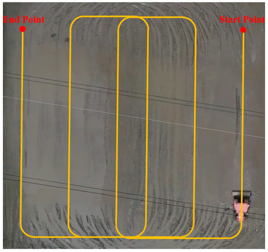
Figure 8.
Reference path for field experiments.
3.2. Field Experiments
To verify the practical operation effect of the proposed algorithm on the tractor, a field operation experiment was conducted in the cooperative experimental field of Runguo Agricultural Company in Zhenjiang City. The reference path for the operation is shown in Figure 8, which is a spiral path commonly used in agricultural scenarios. Specifically, the tractor performs operations along long straight segments; when traveling to the field headland, it lifts the implement and achieves U-turning through a path composed of a quarter-circular arc, a short cross-row straight segment, and another quarter-circular arc. The automatic driving process of the tractor is shown in Figure 9. The experimental platform is the YTO LY1104 agricultural tractor (parameters listed in Table 1), modified with an automatic control system as shown in Figure 1 of Section 2.1.

Figure 9.
Photos of tractors’ autonomous driving in field experiments: (a) Drive straight; (b) Driving around a curve along an arc path. (c) Complete the turn and U-turn.
The field tracking trajectories of the three path tracking controllers are shown in Figure 10.
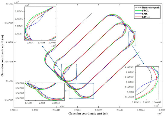
Figure 10.
Results of the tracking trajectories for field experiments.
Lateral error serves as the primary metric for assessing path tracking accuracy. Figure 11 and Figure 12, along with Table 3, collectively provide a comprehensive analysis of this accuracy. Figure 11 illustrates the time series of lateral errors, while Figure 12 presents a box plot of error distribution. Table 3 summarizes key statistical indices, including maximum lateral error, Mean Absolute Error (MAE)—which measures the average magnitude of errors to reflect overall tracking accuracy—Standard Deviation (STD)—which quantifies the dispersion of errors to indicate the stability of tracking performance—and IAE—which accumulates absolute errors over the experimental period to evaluate the total correction demand on the controller.
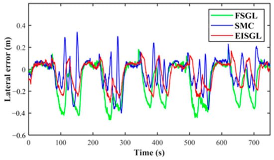
Figure 11.
Results of the lateral errors for field experiments.
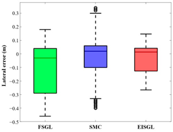
Figure 12.
Box plot of the lateral errors.

Table 3.
Statistics of the lateral errors for field experiments.
Qualitative analysis reveals significant differences in their alignment with the reference path: FSGL exhibits the most obvious trajectory deviation, especially in U-turn segments; at the quarter-circle (radius = 4 m) of the U-turn, the curvature of the FSGL trajectory is approximately 20% smaller than that of the reference path, indicating severe understeering, which is attributed to FSGL only adjusting the control gain through fuzzy rules based on the current lateral error (i.e., the “error-first, compensation-later” logic) and lacking sideslip compensation; when the tractor slips on moist soil, the gain adjustment cannot keep up with dynamic errors, leading to trajectory divergence. The SMC’s trajectory is closer to the reference path than FSGL, but slight fluctuations are observed at the entry and exit of U-turns, which stems from the sliding mode variable structure of SMC—although it enhances robustness against disturbances, the exponential reaching law introduces minor chattering (exacerbated by uneven field soil), resulting in temporary trajectory oscillations. In contrast, EISGL’s trajectory almost overlaps with the reference path in both straight segments and U-turns: the lateral error in straight segments is less than 0.05 m, and the curvature deviation in U-turn segments is less than 5%. This superiority originates from two core designs of EISGL: first, the ESO estimates the real-time sideslip angle to compensate for soil-induced slip, and second, the weighted error term integrates information from future path points (look-ahead points to ), pre-adjusting the desired heading angle to avoid understeering during turns.
In terms of time-series behavior, FSGL exhibits significant error peaks, with a maximum lateral error of −0.46 m at the onset of U-turns. Its convergence is relatively slow, requiring approximately 8 s for the error to decrease from −0.46 m to −0.1 m, and it maintains a steady-state error of around 0.12 m during straight segments. This behavior can be attributed to the fuzzy gain adjustment’s inability to fully counteract drift caused by sideslip. SMC, on the other hand, reduces error peaks to 0.40 m and shortens the convergence time to about 5 s, benefiting from its rapid disturbance rejection capability. However, minor oscillations persist in straight segments, resulting in a steady-state error of 0.08 m. Conversely, EISGL maintains lateral error within a narrow range of −0.26 m to 0.18 m throughout the experiment. It demonstrates smooth error transitions without overshoot at the entry and exit of U-turns, achieving a steady-state error of less than 0.05 m in straight segments. This advantage stems from EISGL’s pre-compensation of future path curvature through and real-time sideslip correction via ESO, which proactively suppress error accumulation.
4. Conclusions
To solve the problems of low tracking accuracy and poor robustness of conventional path tracking controllers for unmanned agricultural tractors—such as ineffective time-varying sideslip angle compensation in unstructured farmland and reactive "error-first, compensation-later" logic during high-curvature maneuvers—this study developed and validated an extended state observer based improved Stanley guidance law. Its key findings and contributions are as follows:
- (1)
- The EISGL controller’s three core modules address traditional limitations synergistically. The ESO accurately estimates the sideslip angle in real time, maintaining near-zero errors in straight-line simulation segments and quickly responding to dynamic changes (0.12 rad) in curved segments to offset tire-soil adhesion uncertainties. The improved Stanley guidance law, by fusing the average tangential angle deviation of look-ahead path points and nonlinear lateral error adjustment, proactively corrects the desired heading angle, eliminating understeering in U-turns that plagues conventional algorithms. The adaptive fuzzy sliding mode controller enhances robustness against field disturbances, suppressing chattering under low-adhesion conditions.
- (2)
- The EISGL controller significantly reduces lateral tracking errors. In field experiments, it achieved a mean absolute error (MAE) of 0.081 m and a maximum error of 0.26 m, outperforming both FSGL (MAE: 0.148 m, Max: 0.46 m) and SMC (MAE: 0.094 m, Max: 0.40 m). This performance is attributed to the proactive heading adjustment using look-ahead path points, which nearly eliminated overshoot during U-turns.
Despite these advancements, this study has certain limitations. The experiments were conducted using a single tractor model without evaluating the effects of different mounted implements, which may alter vehicle dynamics. Additionally, the soil conditions in the experiments were relatively uniform, lacking validation in highly variable terrain. Future work will focus on extending the controller to more complex operational scenarios, integrating multi-sensor fusion for enhanced state estimation, and evaluating performance under a wider range of implements and field types.
Beyond the technical contributions, this research aligns with and supports several United Nations Sustainable Development Goals (SDGs). By enhancing the accuracy and autonomy of agricultural machinery, this work directly contributes to SDG 2 (Zero Hunger) through the potential for increased crop yield efficiency and optimized resource use. The precise path tracking reduces overlapping and missed application areas, promoting SDG 12 (Responsible Consumption and Production) by minimizing the waste of inputs such as seeds, fertilizers, and pesticides. Furthermore, improved operational efficiency leads to reduced fuel consumption and lower greenhouse gas emissions, supporting efforts against climate change under SDG 13 (Climate Action). Lastly, by enabling more controlled and less intrusive field operations, the technology aids in preserving soil structure and health, contributing to SDG 15 (Life on Land).
Author Contributions
Conceptualization, A.W. and X.W.; methodology, A.W., X.J. and K.W.; software, K.W. and X.J.; validation, A.W., X.J. and K.W.; formal analysis, A.W. and X.J.; investigation, A.W., X.J., X.W. and W.C.; resources, A.W., X.W. and W.C.; data curation, A.W., X.J. and X.W.; writing—original draft preparation, A.W. and Q.S.; writing—review and editing, Q.S. and W.C.; visualization, X.J. and Q.S.; supervision, X.W.; project administration, X.W.; funding acquisition, A.W. and W.C. All authors have read and agreed to the published version of the manuscript.
Funding
This research was funded by the National Science and Technology Major Project, grant number 2022ZD0115804, the Common Technology and Product R&D Program of the Agricultural Engineering Department, Jiangsu University, grant number NGXB20240105 and the High-tech Key Laboratory of Agricultural Equipment and Intelligence of Jiangsu Province, grant number MAET202333.
Data Availability Statement
The data presented in this study are available on request from the corresponding author.
Conflicts of Interest
The authors declare no conflicts of interest.
References
- Garg, D.; Alam, M. Smart agriculture: A literature review. J. Manag. Anal. 2023, 10, 359–415. [Google Scholar] [CrossRef]
- Lacoste, M.; Cook, S.; McNee, M.; Gale, D.; Ingram, J.; Bellon-Maurel, V.; MacMillan, T.; Sylvester-Bradley, R.; Kindred, D.; Bramley, R.; et al. On-farm experimentation to transform global agriculture. Nat. Food 2022, 3, 11–18. [Google Scholar] [CrossRef]
- Shen, D.; Liang, H.; Shi, W. Rural population aging, capital deepening, and agricultural labor productivity. Sustainability 2023, 15, 8331. [Google Scholar] [CrossRef]
- Debnath, S.; Paul, M.; Debnath, T. Applications of LiDAR in agriculture and future research directions. J. Imaging 2023, 9, 57. [Google Scholar] [CrossRef]
- Rivera, G.; Porras, R.; Florencia, R.; Sánchez-Solís, J.P. LiDAR applications in precision agriculture for cultivating crops: A review of recent advances. Comput. Electron. Agric. 2023, 207, 107737. [Google Scholar] [CrossRef]
- Wang, T.; Chen, B.; Zhang, Z.; Li, H.; Zhang, M. Applications of machine vision in agricultural robot navigation: A review. Comput. Electron. Agric. 2022, 198, 107085. [Google Scholar] [CrossRef]
- Shin, J.; Mahmud, M.S.; Rehman, T.U.; Ravichandran, P.; Heung, B.; Chang, Y.K. Trends and prospect of machine vision technology for stresses and diseases detection in precision agriculture. AgriEngineering 2022, 5, 20–39. [Google Scholar] [CrossRef]
- Wang, A.; Wang, Y.; Ji, X.; Wang, K.; Qian, M.; Wei, X.; Song, Q.; Chen, W.; Zhang, S. Fuzzy backstepping controller for agricultural tractor-trailer vehicles path tracking control with experimental validation. Front. Plant Sci. 2024, 15, 1513544. [Google Scholar] [CrossRef]
- Ji, X.; Wei, X.; Wang, A.; Cui, B.; Song, Q. A novel composite adaptive terminal sliding mode controller for farm vehicles lateral path tracking control. Nonlinear Dyn. 2022, 110, 2415–2428. [Google Scholar] [CrossRef]
- Ruslan, N.A.I.; Amer, N.H.; Hudha, K.; Kadir, Z.A.; Ishak, S.A.F.M.; Dardin, S.M.F.S. Modelling and control strategies in path tracking control for autonomous tracked vehicles: A review of state of the art and challenges. J. Terramech. 2023, 105, 67–79. [Google Scholar] [CrossRef]
- He, J.; Hu, L.; Wang, P.; Liu, Y.; Man, Z.; Tu, T.; Yang, L.; Li, Y.; Yi, Y.; Li, W.; et al. Path tracking control method and performance test based on agricultural machinery pose correction. Comput. Electron. Agric. 2022, 200, 107185. [Google Scholar] [CrossRef]
- Cao, Y.; Ren, W. Optimal linear-consensus algorithms: An LQR perspective. IEEE Trans. Syst. Man Cybern. Part B Cybern. 2009, 40, 819–830. [Google Scholar]
- Kumar, E.V.; Jerome, J. Robust LQR controller design for stabilizing and trajectory tracking of inverted pendulum. Procedia Eng. 2013, 64, 169–178. [Google Scholar] [CrossRef]
- Zhang, Y.; Gao, F.; Zhao, F. Research on path planning and tracking control of autonomous vehicles based on improved RRT* and PSO-LQR. Processes 2023, 11, 1841. [Google Scholar] [CrossRef]
- Fan, X.; Wang, J.; Wang, H.; Yang, L.; Xia, C. LQR trajectory tracking control of unmanned wheeled tractor based on improved quantum genetic algorithm. Machines 2023, 11, 62. [Google Scholar] [CrossRef]
- Yang, T.; Bai, Z.; Li, Z.; Feng, N.; Chen, L. Intelligent vehicle lateral control method based on feedforward+ predictive LQR algorithm. Actuators 2021, 10, 228. [Google Scholar] [CrossRef]
- Holkar, K.S.; Waghmare, L.M. An overview of model predictive control. Int. J. Control Autom. 2010, 3, 47–63. [Google Scholar]
- Schwenzer, M.; Ay, M.; Bergs, T.; Abel, D. Review on model predictive control: An engineering perspective. Int. J. Adv. Manuf. Technol. 2021, 117, 1327–1349. [Google Scholar] [CrossRef]
- Zuo, Z.; Yang, X.; Li, Z.; Wang, Y.; Han, Q.; Wang, L.; Luo, X. MPC-based cooperative control strategy of path planning and trajectory tracking for intelligent vehicles. IEEE Trans. Intell. Veh. 2020, 6, 513–522. [Google Scholar] [CrossRef]
- Wang, H.; Liu, B.; Ping, X.; An, Q. Path tracking control for autonomous vehicles based on an improved MPC. IEEE Access 2019, 7, 161064–161073. [Google Scholar] [CrossRef]
- Rokonuzzaman, M.; Mohajer, N.; Nahavandi, S. Effective adoption of vehicle models for autonomous vehicle path tracking: A switched MPC approach. Veh. Syst. Dyn. 2023, 61, 1236–1259. [Google Scholar] [CrossRef]
- Zhou, B.; Su, X.; Yu, H.; Guo, W.; Zhang, Q. Research on path tracking of articulated steering tractor based on modified model predictive control. Agriculture 2023, 13, 871. [Google Scholar] [CrossRef]
- Young, K.D.; Utkin, V.I.; Ozguner, U. A control engineer’s guide to sliding mode control. IEEE Trans. Control Syst. Technol. 1999, 7, 328–342. [Google Scholar] [CrossRef]
- Lee, H.; Utkin, V.I. Chattering suppression methods in sliding mode control systems. Annu. Rev. Control 2007, 31, 179–188. [Google Scholar] [CrossRef]
- Sabiha, A.D.; Kamel, M.A.; Said, E.; Hussein, W.M. ROS-based trajectory tracking control for autonomous tracked vehicle using optimized backstepping and sliding mode control. Rob. Auton. Syst. 2022, 152, 104058. [Google Scholar] [CrossRef]
- Yin, C.; Wang, S.; Li, X.; Yuan, G.; Jiang, C. Trajectory tracking based on adaptive sliding mode control for agricultural tractor. IEEE Access 2020, 8, 113021–113029. [Google Scholar] [CrossRef]
- Ding, C.; Ding, S.; Wei, X.; Mei, K. Composite SOSM controller for path tracking control of agricultural tractors subject to wheel slip. ISA Trans. 2022, 130, 389–398. [Google Scholar] [CrossRef]
- Zhang, T.; Jiao, X.; Lin, Z. Finite time trajectory tracking control of autonomous agricultural tractor integrated nonsingular fast terminal sliding mode and disturbance observer. Biosyst. Eng. 2022, 219, 153–164. [Google Scholar] [CrossRef]
- Han, G.; Fu, W.; Wang, W.; Wu, Z. The lateral tracking control for the intelligent vehicle based on adaptive PID neural network. Sensors 2017, 17, 1244. [Google Scholar] [CrossRef]
- Marino, R.; Scalzi, S.; Netto, M. Nested PID steering control for lane keeping in autonomous vehicles. Control Eng. Pract. 2011, 19, 1459–1467. [Google Scholar] [CrossRef]
- Samuel, M.; Hussein, M.; Mohamad, M.B. A review of some pure-pursuit based path tracking techniques for control of autonomous vehicle. Int. J. Comput. Appl. Technol. 2016, 135, 35–38. [Google Scholar] [CrossRef]
- Elbanhawi, M.; Simic, M.; Jazar, R. Receding horizon lateral vehicle control for pure pursuit path tracking. J. Vib. Control 2018, 24, 619–642. [Google Scholar] [CrossRef]
- Yang, Y.; Li, Y.; Wen, X.; Zhang, G.; Ma, Q.; Cheng, S.; Qi, J.; Xu, L.; Chen, L. An optimal goal point determination algorithm for automatic navigation of agricultural machinery: Improving the tracking accuracy of the Pure Pursuit algorithm. Comput. Electron. Agric. 2022, 194, 106760. [Google Scholar] [CrossRef]
- Wang, R.; Li, Y.; Fan, J.; Wang, T.; Chen, X. A novel pure pursuit algorithm for autonomous vehicles based on salp swarm algorithm and velocity controller. IEEE Access 2020, 8, 166525–166540. [Google Scholar] [CrossRef]
- Kim, S.; Lee, J.; Han, K.; Choi, S.B. Vehicle path tracking control using pure pursuit with MPC-based look-ahead distance optimization. IEEE Trans. Veh. Technol. 2023, 73, 53–66. [Google Scholar] [CrossRef]
- Thrun, S.; Montemerlo, M.; Dahlkamp, H.; Stavens, D.; Aron, A.; Diebel, J.; Fong, P.; Gale, J.; Halpenny, M.; Hoffmann, G.; et al. Stanley: The robot that won the DARPA Grand Challenge. J. Field Rob. 2006, 23, 661–692. [Google Scholar] [CrossRef]
- Wang, L.; Zhai, Z.; Zhu, Z.; Mao, E. Path tracking control of an autonomous tractor using improved Stanley controller optimized with multiple-population genetic algorithm. Actuators 2022, 11, 22. [Google Scholar] [CrossRef]
- Sun, Y.; Cui, B.; Ji, F.; Wei, X.; Zhu, Y. The full-field path tracking of agricultural machinery based on PSO-enhanced fuzzy stanley model. Appl. Sci. 2022, 12, 7683. [Google Scholar] [CrossRef]
- Cui, B.; Cui, X.; Wei, X.; Zhu, Y.; Ma, Z.; Zhao, Y.; Liu, Y. Design and Testing of a Tractor Automatic Navigation System Based on Dynamic Path Search and a Fuzzy Stanley Model. Agriculture 2024, 14, 2136. [Google Scholar] [CrossRef]
- Ji, X.; Ding, S.; Wei, X.; Cui, B. Path tracking of unmanned agricultural tractors based on a novel adaptive second-order sliding mode control. J. Franklin Inst. 2022, 360, 5811–5831. [Google Scholar] [CrossRef]
- Sontag, E.D.; Wang, Y. On characterizations of the input-to-state stability property. Syst. Control Lett. 1995, 24, 351–359. [Google Scholar] [CrossRef]
- KrstiC, M.; Kanellakopoulos, I.; KokotoviC, P.V. Nonlinear design of adaptive controllers for linear systems. IEEE Trans. Autom. Control 1994, 39, 738–752. [Google Scholar] [CrossRef]
- Kayacan, E.; Kayacan, E.; Ramon, H.; Saeys, W. Modeling and identification of the yaw dynamics of an autonomous tractor. In Proceedings of the 2013 9th Asian Control Conference, Istanbul, Turkey, 23–26 June 2013. [Google Scholar]
Disclaimer/Publisher’s Note: The statements, opinions and data contained in all publications are solely those of the individual author(s) and contributor(s) and not of MDPI and/or the editor(s). MDPI and/or the editor(s) disclaim responsibility for any injury to people or property resulting from any ideas, methods, instructions or products referred to in the content. |
© 2025 by the authors. Licensee MDPI, Basel, Switzerland. This article is an open access article distributed under the terms and conditions of the Creative Commons Attribution (CC BY) license (https://creativecommons.org/licenses/by/4.0/).