Review

Recent Developments in Understanding Biochar’s Physical–Chemistry

1
Department of Agricultural, Food and Forestry Science, University of Palermo, 90128 Palermo, Italy
2
Department of Industrial Engineering, University of Padua, 35131 Padua, Italy
3
Ithaka Institute for Carbon Strategies, Ancienne Eglise 9, 1974 Arbaz, Switzerland
4
Department of Civil, Environmental and Architectural Engineering, University of Padua, 35131 Padua, Italy
5
Department of Biological, Chemical and Pharmaceutical Sciences and Technologies, University of Palermo, 90128 Palermo, Italy
*
Author to whom correspondence should be addressed.
Agronomy 2021, 11(4), 615; https://doi.org/10.3390/agronomy11040615
Submission received: 9 February 2021 / Revised: 16 March 2021 / Accepted: 18 March 2021 / Published: 24 March 2021
(This article belongs to the Special Issue Management of Soil Organic Carbon for Soil Health in Agroecosystems)

Abstract

:
Biochar is a porous material obtained by biomass thermal degradation in oxygen-starved conditions. It is nowadays applied in many fields. For instance, it is used to synthesize new materials for environmental remediation, catalysis, animal feeding, adsorbent for smells, etc. In the last decades, biochar has been applied also to soils due to its beneficial effects on soil structure, pH, soil organic carbon content, and stability, and, therefore, soil fertility. In addition, this carbonaceous material shows high chemical stability. Once applied to soil it maintains its nature for centuries. Consequently, it can be considered a sink to store atmospheric carbon dioxide in soils, thereby mitigating the effects of global climatic changes. The literature contains plenty of papers dealing with biochar’s environmental effects. However, a discrepancy exists between studies dealing with biochar applications and those dealing with the physical-chemistry behind biochar behavior. On the one hand, the impression is that most of the papers where biochar is tested in soils are based on trial-and-error procedures. Sometimes these give positive results, sometimes not. Consequently, it appears that the scientific world is divided into two factions: either supporters or detractors. On the other hand, studies dealing with biochar’s physical-chemistry do not appear helpful in settling the factions’ problem. This review paper aims at collecting all the information on physical-chemistry of biochar and to use it to explain biochar’s role in different fields of application.

1. Introduction

Global climate change (GCC) is the most important challenge mankind is facing in the modern era. The whole scientific community agrees that the main cause of GCC are greenhouse gases (e.g., carbon dioxide, methane, and various nitrous oxides) which have atmospheric concentrations that depends not only on natural Earth emissions (e.g., biomass decay and burning, oceans, volcanos, earthquakes) but also, and mainly, on anthropic activities such as agriculture, deforestation, and burning of fossil fuels [1].
To account for the effects of global climate change on living systems, the term “environmental sustainability” has become keyword for scientists and politicians. It intends to maintain environmental resources, thereby making them available for future generations [2]. To this aim, one of the strategies applied to contrast GCC effects is to limit the impact of anthropic activities on the environment, thus reducing the consumption of air, water, soils, and sediments [3]. A possible and viable alternative to fossil fuels is, for example, the use of bioenergy.
The term “bioenergy” refers to renewable and clean energy sources that derive from biomasses such as food residuals, agricultural crops, animals, and municipal solid wastes [4]. Biomasses can be transformed into bio-ethanol (the prefix “bio” is always added when a compound is obtained from biomasses; therefore, bio-ethanol is the very well-known CH3CH2OH, which is produced by using biomasses), syngas (a mixture of H2, CO, CxHy, N2, CO2, with a relative amount depending on the biomass used for its production), and a solid residue (that is referred to as “biochar”, “char”, “charcoal”) which can be used also to obtain different forms of energy.
Nowadays, bio-ethanol is used in many countries as fuel for internal combustion engines [5], whereas syngas is burned either to obtain thermal energy [6] or to be transformed into biofuels (i.e., bioethanol and biodiesel) for automotive uses [7].
Biochar/char/charcoal are highly porous fine-grained carbonaceous substances. While charcoal is mainly used for thermal energy [8], biochar is a useful material for many different applications such as soil amendment [9,10,11,12,13,14,15,16,17,18,19], soil decontamination [20], water treatment [21,22,23,24], food additive for animal feed [25], 3D printing [26], and electronic devices [27].

1.1. What Is Biochar?

As we mentioned above, three terms—biochar, charcoal, and char—can be applied to identify the solid black residue occurring from bioenergy production. Up to a few years ago, all of them were used synonymously in order to indicate the carbonaceous material produced by thermal degradation in oxygen-starved conditions (also referred to as pyrolysis) of biomasses from plant and/or animal origin [28,29]. For thousands of years, it has been the basic material for cooking, space heating, and forging of metal tools [28,30]. Moreover, the aforementioned material has also been used for centuries as soil amendment, animal bedding, medicine, and feed additive [28,30]. However, knowledge about its uses has been partly lost over time and has been only recently rediscovered [28,30]. During the last decade, this material became a major topic for many research groups due to the fact of its potential impact on slowing global warming and on its capacity to restore degraded soils [16,31,32,33,34,35,36,37]. Figure 1 reports, as an example, that the number of scientific papers containing the word “biochar” increased from less than 50 at the end of the nineties and the beginning of the 2000s to more than 3500 in 2020.
To understand why biochar/charcoal/char is very helpful in reducing the effects of global warming, one has to consider that carbonaceous plant metabolites produced by photosynthesis return back to CO2 when plant materials are allowed to decompose (Figure 2A). However, if plant residues are thermally degraded in oxygen-starved conditions, up to 60% of the original plant C can be transformed into biochar/charcoal/char (Figure 2B). Mineralization of this carbonaceous material back to CO2 is extremely slow when it is used to improve soil quality. For this reason, it provides a pathway for temporary CO2 subtraction from the global C cycle and reduces the concentration of carbon dioxide in the atmosphere [34].
The survey of Terra preta do indio in Brazil, historical Māori gardens in New Zealand, and some Anthrosols in Northern Europe [38,39,40] confirmed the contribution of the aforementioned carbonaceous material in improving soil fertility. Soils of these regions suffer from low fertility. Amazonian rain forest soils are usually thin, red, acidic, and infertile; those in southern New Zealand do not support horticultural production, which is, instead, possible in the warmer and more fertile volcanic areas placed in the northern part of the country [41]; many areas of The Netherlands, Denmark, and Belgium are characterized by sandy soils showing a relatively high content of easily weathered minerals [38]. All those soils were made more fertile by addition—in ancient times—of organic material, including biochar/charcoal/char, thereby suggesting that such a carbonaceous material can be directly involved in the amelioration of the soil properties and the improvement of crop production.
Regardless of what is reported in many textbooks about the lack of a scientific definition for biochar/charcoal/char [42], it must be pointed out that Lehmann et al. [9], Lehmann and Rondon [43], and Lehmann and Joseph [44] have defined the term “biochar” as the carbonaceous material—obtained by biomass pyrolysis—which is deliberately applied to soils as an amendment. According to this, it appears clear that the terms “charcoal” and “char” apply to the material which is not deliberately applied to soils. In particular, according to Knicker [45] charcoal can be intended as the carbonaceous material incorporated into soils as a consequence of forest fires, while from Bao et al. [46] and He et al. [47], char can be considered as the carbonaceous material produced for the achievement of new materials in industrial chemistry.
The biochar definition given by Lehmann’s group [9,43,44] appears weak for different reasons. On the one hand, it does not fulfil the sustainability concept reported in Brown et al. [2]. This definition implies that many plant biomass species can be used for biochar production regardless of the time needed for their replacement. This means that, if not controlled by sustainability standards, their use for biochar production may pose serious problems for biodiversity protection, wildlife habitats, soil protection, and water production, thereby limiting the eco-sustainability of biochar applications. On the other hand, the definition by Lehmann and coworkers [9,43,44] is only oriented towards agronomic uses. In fact, it does not consider production methodologies, and it does not include the very important greenhouse gas reduction property.
It is not possible to provide a single general definition for sustainability. It depends on the field where it is applied. As an example, sustainability is the ability to manage “a resource for maximum continuing production, consistent with the maintenance of a constantly renewable stock” when it deals with biological resources [2]. In agriculture, sustainability is “the ability of a system to maintain productivity in spite of a major disturbance” [2]. In the energy field, the term is associated with the “transition from a global energy system based on consuming depletable fossil fuels to a sustainable system based on non-depletable fuels” [2]. When dealing with ecology, sustainability refers to the conservation of the micro- and macro-environments where flora and fauna can survive [2]. All these sustainability concepts must be fulfilled in order to produce a biochar which is environmentally sustainable. To this aim, the European Biochar Foundation [48] substantially changed the definition by Lehman and co-workers [48]:
“Biochar is a porous, carbonaceous material that is produced by pyrolysis of plant biomasses and is applied in such a way that the contained carbon remains stored as a long-term C sink or replaces fossil carbon in industrial manufacturing. It is not made to be burnt for energy generation”.
According to this more general definition, the only biomasses that can be used for biochar production are those obtained by fast growing plants, plant residues from certified forestry management, agricultural residues, and organic wastes from urban areas [28]. Moreover, the European Biochar Certificate (EBC) definition accounts also for all the possible uses of biochar as a new material such as its application in paper and cellulose industry, for advanced building materials, electronics, 3D printing, decontamination, such as in water and sewage treatment, mining, air filtration, textile industry, and animal farming [49]. Table 1 reports the types of biomasses which can be used to produce biochar according to the EBC [48].

1.2. Is Biochar Risky?

One of the main concerns about the application of biochar to soils (or in general to the environment) is the potential risk of producing contamination and pollution of the environmental resources [3]. The idea about the potential risk of biochar applications comes directly from its chemical nature. Biochar is made of poly-condensed aromatic rings where stacked crystalline graphene sheets and randomly ordered amorphous aromatic structures can be identified [50] (Figure 3).
In the aforementioned structure, hetero-atoms, such as O, N, P, and S, are predominantly incorporated within the aromatic rings, thereby contributing to the complex surface chemistry and reactivity of biochar [50].
The chemical nature of biochar induces to think that environmental release of polycyclic aromatic hydrocarbons (PAHs, persistent pollutants formed during pyrolysis) may occur [3,52,53]. Based on this assumption, they put forward the precautionary principle and limit biochar field applications. However, in the last decade, many papers appeared in the literature, all dealing with the high environmental stability of biochar when it is applied to soils [3,40,52,53,54,55,56,57,58,59,60,61,62,63]. In particular, Rombolà et al. [55] reported not only that the concentration of total PAHs remains below the maximum acceptable concentration established in many European countries, but also that their concentration decreases within five years after the application of biochar to soils. However, it is noteworthy that Rombolà’s paper [53] poses a serious methodological problem. It is not clear whether PAH reduction following biochar application is due either to leaching or to PAH decomposition. The former may still be a risk because of possible accumulation in groundwater and food magnification. Polycyclic aromatic hydrocarbons decomposition occurs mainly through fragmentation. Over the long term, most of the biochar nanoparticles leach out. Although these are not toxic, at present, it is not possible to exclude any groundwater contamination risks [64]. Regardless of the possible mechanisms related to PAH reduction in soils after biochar application, the European Biochar Foundation established a PAH threshold of 4 mg kg−1 [48], which is far below the background contamination. In addition, as reported by Conte et al. [28]:
“Biochar shows a very good adsorption potential for hydrophobic materials […]. For this reason, the USEPA suggests charcoal as the best available technology for the treatment of hydrophobic contamination. […] the concern about possible dioxin content in biochars is overstated. On the one hand, the amount of dioxins in biochars that have been analyzed to date was very low […]. On the other hand, any dioxins present are strongly bound to biochar, thereby being unavailable for plant nutrition and to the food chain […]”.
In other words, biochar adsorbs more environmental PAHs and other hydrophobic pollutants than it releases.
Table 2 reports the main characteristics to produce a biochar which follows the EBC guidelines. According to what has been reported above, the answer to the question regarding biochar’s risk to health can only be that biochar is not risky provided that it is produced and used according to the recommendations from the European Biochar Foundation [48].

1.3. Aim of This Work

Biochar research received a great deal of interest in the last decade and its role in many different applications has been clarified. However, the understanding of biochar behavior seems more empirical than relying on a well-structured theoretical framework. For this reason, we intend to discuss the most recent literature to provide a general and critical overview of the newest findings on biochar’s physical chemistry, thereby highlighting all the main information useful to disclose the molecular mechanisms of biochar functioning. Due to its multivalent characteristics, we will focus not only on the mechanisms of biochar applied to soils, but also on its role in environmental remediation.

2. Making Biochar: A Brief Summary of the Main Production Methodologies

Notwithstanding that the focus of this review paper is not on biochar production, a brief summary of simple techniques used to obtain the aforementioned material is given. The idea is to provide an easy tool for inexperienced readers who want to approach biochar science. The production methods listed here are not exhaustive of the whole range of techniques used to obtain biochar; therefore, readers are recommended to consult the publications in references [44,65,66] for wider and more detailed information.
The different techniques applied for biochar production provide materials with typical characteristics, making them reliable for many specific uses [49]. As an example, when only small amounts of biochar are needed for lab studies, the lab–muffle–furnace method can be applied (Appendix A). This home-made, quick procedure to transform any kind of biomass is affected by the researcher’s awareness and by the impossibility of correctly controlling all the production parameters (e.g., atmosphere composition, quenching methodology). Therefore, a reliable approach to the lab–muffle–furnace method would be for the same researcher to undertake the production of biochar for the entire research group. This is the only way to obtain a carbonaceous material with repeatable characteristics.
A valid alternative to obtain biochars with reproducible chemical–physical properties is the use of lab-pyrolizers (Appendix B). These are designed to adjust the pyrolyzing atmosphere and quenching procedures. Depending on the pyrolizer characteristics, the amount of biochar that is produced can be in the order of tens of grams, which is at least ten times more than the amount obtained by the lab–muffle–furnace method. Being highly reproducible, the advantages of the use of lab-pyrolizers rely on the fact that the obtained biochar can be used for the production of new materials such as electrodes [67], sorbent for specific pollutants [68], or even for medicine [49].
The hydrothermal carbonization (Appendix C) is usually applied to retrieve biochars (which in this case are referred to as hydrochars) having very good fertilizing characteristics [69,70]. This is mainly due to the presence of residual polysaccharide and polypeptide units that are not thermally decomposed by the mild temperature conditions used during the process [71].
When larger amounts of material are needed for agricultural purposes, the Kon-Tiki kiln can be a useful tool for biochar production (Appendix D). This method allows control of the quenching procedure, whereas no control of the pyrolysis temperature is achieved. The biochar obtained by this home-made procedure appeared to be very effective in increasing pumpkin production [72].
In Appendix E, the industrial thermochemical carbonization (also referred to as gasification) is briefly summarized. The method is thought to produce syn-gas which can be applied for energy production, while biochar is obtained as a low-cost by-product [6]. The latter can be applied to achieve different aims such as agricultural purposes [16], environmental remediation, electrical energy storage, electrochemical sensors, and catalysis [73].

3. Biochar Physical–Chemical Properties

3.1. The Effect of Feedstock Nature

The nature of the biomass used for biochar production appears to play a major role in addressing its chemical–physical properties [28]. Different feedstocks show different composition in terms of cellulose, hemicellulose, lignin as well as inorganic components [21,74]. These differences result in a different biomass behavior during the thermal degradation described in the previous paragraph [74,75]. In particular, hemicellulose is the first to undergo decomposition at a temperature ranging between 200 and 260 °C, while cellulose breaks down at 240–350 °C and lignin at 280–500 °C [74]. The pyrolysis mechanism of hemicelluloses starts with a depolymerization producing oligosaccharides. Therefore, xylan chain cleavage and molecular rearrangement produces a xylopyranose. The xylopyranose is further degraded to small molecular weight compounds such as furfural and fragments containing two or three carbon atoms. As for the hemicellulose, also cellulose is first depolymerized into oligosaccharides. Then the glucosidic bonds of the oligosaccharides are broken to produce D-glucopyranose. The intramolecular rearrangement of D-glucopyranose produces levoglucosan. The latter further decomposes to form small molecular weight compounds. Pyrolysis of lignin generates phenolic compounds such as guaiacol-like, phenol-like, syringol-like, and catechol-like systems [74].
The relative abundances of the biomass components described above effect reactivity and yield, thereby affecting the ratios between the volatile products (e.g., bio-oil and gas) and the biochar [74,75,76]. For instance, biomasses with a low content of lignin, minerals, and nitrogen are used to produce bio-oil and fuel-gas. Conversely, feedstock containing larger amounts of lignin are mainly applied to achieve biochar [8]. As a rule of thumb, the biochars produced from woods have low ash and high carbon contents, whereas the thermal degradation of herbaceous biomasses, biosolids and manures result in biochars with low carbon content and larger amounts of ashes, nitrogen, phosphorus, potassium, and sulphur [44,77].
Besides their chemical nature, the biomasses used for biochar production affect also its porosity and, therefore, its adsorptive properties [44,78]. During the thermal degradation, the loss of volatile organic compounds results in a volume reduction. Consequently, the arising mineral and carbon skeleton retain the rudimentary feedstock porosity and structure. The residual cellular structures of botanical origin that are present and identifiable in biochars contribute to the majority of the biochar macro-porosity [44]. This is confirmed by microscopic investigations showing the presence of aligned honeycomb-like groups of pores (Figure 4). The latter ones are due to the carbonaceous skeleton arising from the biological capillary structure of the raw material. Finally, the large-sized pores serve as a feeder to lower-dimension pores [44].
The number of inorganic components in the feedstock also plays an important role in determining the physical structure of biochar. Depending on the applied processing conditions (outlined below), ash fusion or sintering may dramatically change the physical and structural composition of biochar.

3.2. The Biomass Pretreatment

The chemical–physical biochar characteristics depend not only on the feedstock’s nature but also on the pretreatments to which it was subjected. Pretreatments are usually applied to facilitate thermal degradation. The hierarchical and recalcitrant nature of biomasses (due to the intricate structure where cellulose, hemicellulose, and lignin are rigidly associated through non-covalent bonds and covalent cross-linkages) prevent any easy disruption, thereby causing undesirable energy expenditure when biomass thermal degradation is used for energy production (e.g., gasification). The advantages of biomass pretreatments are also related to the formation of solid by-products with specific properties enabling their use in wastewater treatments, air cleaning, soil remediation, and catalytic purposes to facilitate energy production [8,76,79,80,81,82,83]. In particular, washing biomass prior to pyrolysis with either acidic or basic solutions may remove up to 70% of the initial minerals contained in the feedstock [79,84,85]. However, the use of dilute acid and hot water results in a slight decomposition of hemicellulose. Conversely, the application of dilute alkali disrupts lignin structure and solubilizes hemicellulose. As a consequence, the thermal degradation applied after the acid/base treatment achieves a higher yield in liquids (tar) and gases at the expense of the solid residue [79,84,85]. The latter, when obtained after biomass treatment with a 1:1 (v:v) HNO3/H2O2 solution, appears to have enhanced adsorption capacity for cadmium from high concentration solutions as compared to biochars obtained from non-pretreated biomasses [86]. This difference can be explained assuming that the treatment favors biochar mesoporosity.
The three dimensional structure of the biomass can also be altered by the use of ionic liquids (ILs) [79]. These are poorly coordinated melted salts made by at least one large organic ion (possibly with a delocalized charge) with a relatively low reticular energy [87]. When biomass is placed in an ionic liquid, the H-bond net is broken by the interactions with the IL cation and anion moieties (Figure 5), thereby providing a material that can be better used for energy purposes (i.e., high yield in biofuels rather than biochar) [79]. However, when the biomass is first heated in concentrated sulphuric acid then treated with IL, a functionalized IL-biochar is obtained. The latter is successfully applied as a catalyst in cellulose dissolution for biofuel production [88,89].
Biochar characteristics can be modified also by treating biomasses with metals, e.g., Mg, Fe, Ca, and Al (usually as nitrogen-containing or chloride salts or by electrodeposition) prior to the thermal degradation [80]. The role of the metals is to enhance biochar adsorption properties, thereby making it a good material for environmental remediation [80]. Enhancement of the biochar’s adsorptive capacity following this treatment can be explained by the Lewis acid-like behavior of the metals added to biomasses prior to the pyrolysis.
Other biomass pretreatments are: (i) the electrospinning of a cellulose acetate solution with subsequent deacetylation and pyrolysis in order to produce carbon fibers to be applied for the production of electrodes [90]; (ii) the low-temperature pre-carbonization combined with KOH chemical activation in order to retrieve tubular nanomaterials to be applied for the achievement of super-capacitors [91]; (iii) the addition of (NH4)2HPO4 before carbonization in order to increase biochar porosity, cross-linking, and availability of nitrogen and phosphorous [91]. A complete review of biomass pretreatments for the achievement of biochars for the production of new materials is reported in Bi et al. [27].

3.3. The Influence of the Pyrolysis Conditions

The experimental conditions applied during the biomass thermal treatments (e.g., temperature and atmosphere) greatly affect biochar characteristics and properties. Therefore, biochar value in terms of its performance for its possible application (e.g., agriculture, soil carbon sequestration, catalyst) is strongly dependent on how pyrolysis is conducted. In the following sub-sections, the most important effects of pyrolysis conditions on biochar characteristics are reviewed.

3.3.1. Temperature Effect on the Amount of Carbon in Biochars

Pyrolysis temperature significantly influences the final biochar structural and physicochemical properties. This is due to the release of volatiles and the formation and volatilization of intermediate melts [77,92,93,94]. Many studies indicate that the higher the temperature, the larger is the biochar carbon-content since loss of nitrogen, hydrogen, and oxygen are recorded [77,92,93,94,95]. The biochars produced at low temperature (<350 °C) reveal a carbon content below 60% (w/w), while as the temperature increases in the range 400–500 °C, the carbon-content increases to 60–80% (w/w). For temperatures as high as 500 °C, the carbon content reaches values larger than 80% (w/w). However, the latter case is valid mostly for wood-derived biochar [44]. When animal residues (e.g., manure) are used, the carbon content reveals an opposite trend [96,97]. This is explained by the effect of the large amount of ashes present in the biomasses from animal origin [97].

3.3.2. Temperature Effect on the Chemical Nature of Biochar Components

Besides the changes of carbon content in biochars, also the chemical nature of the biochar organic components varies with temperature. With increasing temperatures, the amount of alkyl carbons decreases, and aromatic residues increases [44,98,99] (Figure 6). From approximately 250–450 °C, the amount of alkyl and aromatic moieties increases, while if the temperature reaches ≥500 °C, the resulting biochar is made by highly recalcitrant forms of organic matter, i.e., poly-condensed aromatic hydrocarbons (Figure 6). Therefore, the biochars produced at high temperatures (≥500 °C) are chemically more stable and more resistant to microbial and abiotic degradations than those obtained at lower temperatures.

3.3.3. Temperature Effect on Biochar Ash Content

Temperature increase also results in a decreased amount of the final solid product, with a concomitant increase in the ash content due to the naturally occurring inorganic components in all biomasses [92,93,94]. As an example, the biochar produced from chicken manure revealed an ash content increasing from 40% to 60%, as the temperature rose from 300 °C to 600 °C [77]; the ash content in the biochar from apple tree branches varied 6–9% as the temperature rose from 300 °C to 600 °C [93]; the biochar obtained from pine sawdust evidenced an increase of the ash content from 1% to 2% by increasing the pyrolysis temperature from 350 °C to 750 °C [94]; the ash content in a biochar obtained from pea straw increased from 15% to 24% as the temperature rose from 350 °C to 750 °C [94]; the biochar from coconut flesh waste showed an ash content varying from 5% to 8% as the temperature was changed from 350 °C to 600 °C [95]. These findings can be explained by considering that the higher the temperature, the larger is the amount of volatile organic compounds (VOCs) produced during the pyrolysis, thereby leading to an amount of solid biochar smaller than that obtained at lower temperatures.

3.3.4. Temperature Effect on Biochar Surface Properties

The progressively larger amount of volatile organic components released from the feedstock with rising temperatures is responsible for the reduction of the surface functional groups which, in turn, cause the adsorption properties of biochars [39,100,101,102,103]. According to Chun et al. [100], low-temperature biochars (that is, those obtained at 300–400 °C) revealed an amount of polar groups (e.g., –OH, –COOH, –C=O etc.) larger than those obtained at temperatures above 500 °C. Because of this, Uchimiya et al. [15,104] reported that biochars obtained at temperatures ≥500 °C revealed a lower capacity to trap heavy metals. Furthermore, the reduction of the adsorption capacity is due also to the biochar’s physical structure as the temperature increases [44,104,105,106]. In particular, the release of the volatile organic components generates pore structures similar to those of the biomass cells (see above). Pore volume and average pore size (i.e., the porosity) increase as the temperature rises up to approximately 500 °C. Above this temperature, pore coalescence and ash melting occur, thereby resulting in a reduction of the porosity [91,107,108]. Figure 7 schematically summarizes pore formation during biomass thermal degradation. The leftmost side of the figure represents the honeycomb-like cells in the biomass prior to the pyrolysis. As the temperature increases to 500 °C, the volatilization of the organic components produces holes as schematized in the central part of Figure 7. Finally, above 500 °C, the high pressure generated by salt melting, together with the production of progressively larger amounts of VOCs, provokes disruption of cell walls and pore coalescence (at the rightmost side of Figure 7), thereby allowing reduction of biochar surface area and capacity to retain organic and inorganic pollutants [107].

3.3.5. Effect of Pyrolysis Heating Rate and Holding Time

Three modes to perform pyrolysis can be recognized. As reported in Table 3, they differ for the heating rate, that is the ramp applied to reach the pyrolysis temperature, and the holding time, that is the time during which the heating temperature is maintained [109,110].
Fast pyrolysis is carried out by applying very high heating rates (that is in the order of hundreds of degrees Celsius per seconds, °C s−1) and a very short holding time (<2 s) (Table 3). Under the aforementioned conditions, the heating rate is so rapid that the biomass reaches the pyrolysis temperature before any thermal decomposition starts [111]. This mode is applied to obtain high yields of bio-oils that come from the condensation of the volatile organic compounds generated by the biomass heating [112]. Bio oils—mainly composed of 20–25% water, 20–25% water-insoluble-lignin, 25–30% organic acids, 5–12% non-polar hydrocarbons, 5–10% sugars and 10–25% other oxygenated compounds [21]—are used for the production of electrical energy. If the aim of fast pyrolysis is to produce a maximum quantity of bio-oils compared to biochar and syngas, usually conditions need to be accounted for: fine particle size of the biomass to be pyrolyzed (<1 mm), careful control of the final temperature (around 450–550 °C), heating rate > 200 °C s−1, short hot vapor residence time (around 2 s), and rapid cooling of the vapors [111,112,113]. When the fast pyrolysis is conducted at a temperature ranging between 700 °C and 1000 °C, hydrogen gas is produced in addition to bio-oils [114].
The conventional or mid pyrolysis is conducted by applying a heating rate of approximately 20 °C s−1 and a pyrolysis temperature usually not above 600 °C held from a few minutes up to a few hours (Table 3) [21,112,115]. This mode is applied to obtain a better biochar yield compared to the fast pyrolysis.
The slow pyrolysis mode—the oldest one, used for thousands of years to produce biochar for agricultural purposes [21,44,112]—is conducted by applying very low heating rates, low to moderate temperatures (around 400 °C) and long reaction times (up to days) (Table 3). The long holding time ensures the conversion of condensable vapors into biochar and non-condensable gases. Unlike fast pyrolysis, the slow one does not necessarily need a fine feedstock particle size (smaller than 1 mm). In fact, raw materials that are not available as powders or fine particles are usually used [116]. Slow/conventional and fast pyrolysis generate different solid bio-carbon products, even when the same raw biomass materials are used. The most significant differences include the evolution of the specific surface area resulting from the development of a porous structure during the pyrolysis process, and the average pore size and pore size distribution [27].

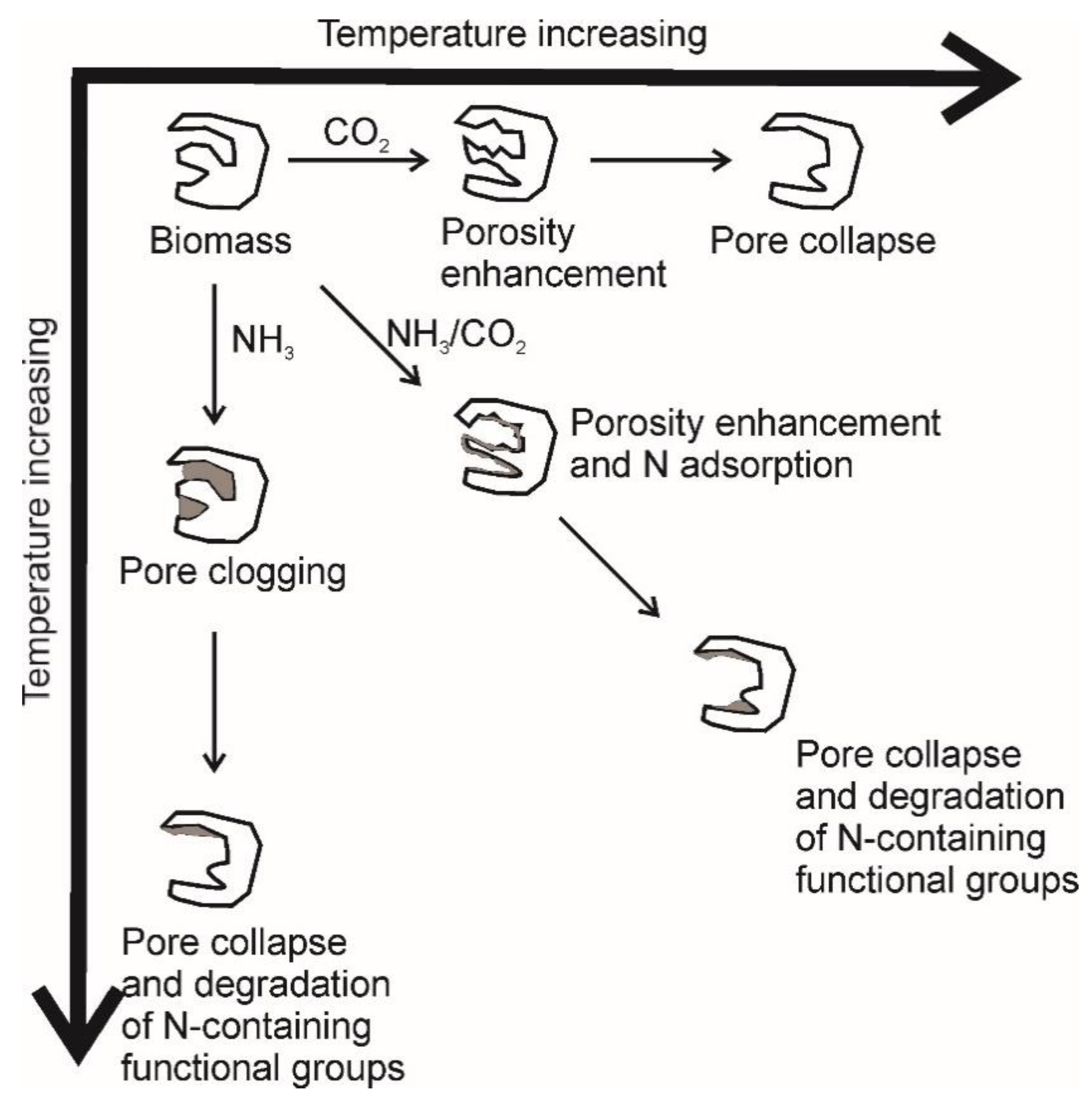
3.3.6. Effect of the Pyrolysis’ Atmosphere

Apart from temperature, heating, and holding times, also the atmosphere used during the thermal degradation influences the yield of the pyrolysis products and the biochar chemical–physical characteristics. As an example, Guizani et al. [117] reported that an atmosphere of carbon dioxide applied during the pyrolysis was responsible for the lower biochar yield as compared to the pyrolysis conducted under an N2 atmosphere. This was explained by suggesting that carbon dioxide can hinder tar polymerization according to Equation (1) (tar polymerization is one of the secondary reactions contributing to biochar formation), can react with methane and hydrogen according to Equations (2) and (3) (thus altering syngas composition), and may favor biochar degradation via the Boudouard reaction described in Equation (4) [117]:
C n H m + nCO 2 2 nCO + m 2 H 2
CO 2 + CH 4 2 H 2 + 2 CO
CO 2 + H 2 H 2 O + CO
CO 2 + C 2 CO
Guizani et al. [117] also reported that the biochar produced in a CO2 atmosphere has larger surface area and lower H/C and O/C ratios than those produced in an N2 atmosphere.
These characteristics have been related to the better adsorption properties for organic and inorganic contaminants as compared to the same materials obtained in an N2 atmosphere [118]. The ameliorated adsorption properties of the biochars obtained in a CO2 atmosphere may also suggest a better nutrient exchange ability when they are applied to soils as amendments. However, no studies have been found to confirm such an expectation.
The results from Guizani et al. [117] have been confirmed by Fan et al. [118], Valdés et al. [119], and Luo et al. [120], whereas only partially by Molenda [121]. In particular, the latter reported that “biocarbon obtained in an atmosphere of carbon dioxide is characterized by a higher proportion of oxygen compared to the product produced in a nitrogen atmosphere”. The differences among these studies lay in the different pyrolysis modes used to perform the CO2-driven thermal degradations. Fast pyrolysis was applied in Guizani et al. [117], Fan et al. [118], Valdés et al. [119], and Luo et al. [120], whereas slow pyrolysis followed by slow biochar cooling to room temperature was used in Molenda [121]. It is conceivable that the slow pyrolysis conditions may have avoided removal of the oxygenated functional groups (revealed by means of the infrared spectroscopy) laying on the surface of the biomass feedstock.
An alternative to carbon dioxide and/or nitrogen atmosphere is the application of an ammonia atmosphere. When NH3 is used to drive thermal degradation of biomasses, nitrogen-enriched biochars are obtained. They can be used either as plant fertilizers or useful activated carbon in materials science (e.g., electronic, optic or transmission applications) [122,123,124]. Ammonia leads to the formation of pyridinic-, pyrrolic-, quaternary-N and pyridine-N-oxide groups.
N-activated biochars can be also obtained via the application of an atmosphere made by a mixture of carbon dioxide and ammonia. The results by Xiong et al. [125] and Zhang et al. [126] showed that five different chemical pathways can conceivably occur on the biomass surface during the thermal degradation (Figure 8). In pathway 1, the alcoholic moieties can react with ammonia generating primary amines. The latter can combine with carbon dioxide to provide N-alkyl ammonium salts and N-alkil carbamates. Pathway 2 shows that, in the presence of ammonia, ether moieties are transformed to secondary amines. The latter combine with carbon dioxide to produce N,N-dialkyl ammonium salts and N,N-dialkyl carbamates. Primary and secondary amines (coming from Pathways 1 and 2, respectively) can react with each other in the presence of carbon dioxide to produce N-alkyl ammonium salts and N,N-dialkyl carbamates (Pathway 3). The N-alkyl carbamates from Pathway 1 may rearrange with water expulsion to produce isocianates (Pathway 4). Finally, the N-alkyl carbamates from Pathway 1 and the N,N-dialkyl ammonium salts from Pathway 2 can condense to form N-alkyl, N’,N’-dialkyl urea derivatives (Pathway 5). The simultaneous presence of all the aforementioned moieties obtained by the chemical transformations of the biomass surfaces appear to be responsible for the very high carbon dioxide affinity of the produced biochars [125,126]. This may suggest that the CO2/NH3-obtained biochars can have different effects when applied to soils. On the one hand, they can work as nitrogen suppliers to plant nutrition. On the other hand, they can trap atmospheric CO2 in soils, thereby contributing to the mitigation of global climatic change.
Besides the effects on the biochar surface chemistry, the CO2/NH3 atmosphere also affects pore formation and size [125,126]. Figure 9 shows that the atmosphere made solely by carbon dioxide first improves pore volume and surface area as the temperature is raised up to a value of around 700 °C. Above 800 °C, pore collapse occurs. Therefore, pore volume and surface area reduction are observed. As the thermal degradation is carried out in an ammonia atmosphere, pore clogging with reduction of porosity and surface area is observed up to a temperature of around 600 °C. As the temperature increases, the N-containing groups (generated by the reactions between ammonia and the walls of the biomass pores) are degraded. At the same time, pore collapse occurs. When the CO2/NH3 mixture is used as pyrolysis atmosphere, a synergic effect of both gases is observed. While carbon dioxide allows pore volume and surface area improvement, ammonia reacts with the pore walls, thereby forming a kind of glue-like layer which improves the adsorption properties of the biochar as compared to the materials obtained either in pure CO2 or NH3 atmospheres. As the temperature is raised above the value of around 800 °C, pore collapse and degradation of N-containing groups occurs [125,126].
The amount of oxygen-containing surface functional groups with the aim to produce biochar having a high affinity for metal ions and, therefore, being possibly applied for wastewater treatments, has been obtained by means of application of air steam under mild temperature conditions (that is temperatures ~ 300 °C) [127]. The mild temperatures are needed to prevent biomass burn-off while oxygen-functionalization occurs (Figure 10). The advantage of this oxygen-rich carbonaceous material is related also to its high cationic exchange capacity [127] which makes it potentially a useful soil fertilizer.

3.3.7. Effect of Co-Pyrolysis

The term co-pyrolysis refers to a process where two or more different feedstock are used to produce materials with a wide range of applications. As an example, co-pyrolysis is applied to obtain sustainable bio-fuels, when biomasses are mixed with coal [128,129] or some types of plastics [130,131,132,133]. The presence of the co-pyrolysis materials allows yield efficiency in the production of bio-oils, thereby leading to the conclusion that co-pyrolysis may satisfy two different types of needs. On one hand, it can provide liquid materials that can be applied as biofuels, thus reducing the use of fossil fuels, and contributing to the mitigation of the global climatic changes. On the other hand, it allows a better management of plastic waste disposal. Plastic pollution is one of the main environmental problems humans are currently facing [134]. Although the biochar yield is lower than in the absence of co-pyrolyzing materials, the solid carbonaceous products resulting from co-pyrolysis appear more efficient in adsorbing organic and inorganic pollutants than the biochar from non-co-pyrolyzed biomasses [130,131,132,133,135]. Moreover, Brebu et al. [136] also found that the co-pyrolyzed biochar reveals higher calorific values compared to pyrolysis of biomasses alone.

3.4. Post-Pyrolysis Chemical and Physical Biochar Functionalization

The properties of biochar can be modulated after pyrolysis, thus providing new materials to be used in very different and often not even connected fields. As an example, He et al. [137] and Liu et al. [138] report a persulfate post pyrolysis treatment of biochars produced at different temperatures. Biochars activate either formation of radical sulfate ( · SO 4 ) or active oxygen ( · OH ) which are the main agents responsible for the degradation of the organic pollutants in biochar treated soils and water.
An innovative, costless, and highly efficient way to produce a biochar with surface areas larger than 120%, compared with the typical surface areas in carbonaceous materials from slow pyrolysis, is the hydrodynamic cavitation [139]. Cavitation is a physical phenomenon occurring when a liquid surrounding a solid material is accelerated. Flow acceleration decreases liquid pressure on the surface of the solid system, thereby provoking the formation of bubbles. Once the bubbles collapse, high-pressure waves are formed, and new pores are generated on the surface of the biochar (Figure 11), leading to an improvement of its surface area. The advantage of the hydrodynamic cavitation in designing new types of biochars is its possible integration with other consolidated methods, such as hydrothermal carbonization and chemical activation, possibly leading to effective synergism [139].
When metal-containing solutions are soaked in biochars, new composites are obtained [80]. The presence of the metals allows enhancement of biochar’s surface adsorption features. As an example, hydrophilic biochars have been prepared with zero-valent iron nanoparticles in order to be applied in environmental remediation to remove organic [140,141,142] and inorganic [143] contaminants. Finally, ball milling has been shown to increase the external surface areas of low temperature biochars, while for higher temperature biochars with relatively low surface area, ball milling appeared to increase both external and internal surface areas [144]. Regardless of the temperature-driven biochar production, ball-milled biochars showed high affinity for metal ions via formation of metal–π interactions with the graphitic biochar structure.

3.5. Innovative Functionalization Strategies

As outlined above, biochar can be conceivably considered a new generation material that can have many different uses and applications. In the following subsections, we discuss the most recent developments in biochar functionalization, and the innovative strategies which are able to make biochar even more versatile than expected by the studies we analyzed so far.

3.5.1. Magnetic Biochars

As reported above, many biochars have been tested for their ability in environmental remediation. However, when applied to soils and water, these materials are difficult to remove. Therefore, new strategies have been developed to functionalize biochars with magnetic nanoparticles such as Fe2O3, FeOOH, and Fe3O4 [145]. The resulting carbonaceous materials can then be removed through the application of a magnetic field. Two different pathways can be used to make biochars magnetic. In particular, either pyrolysis or hydrothermal carbonization can be applied on the biomass feedstock treated with iron-containing solutions in alkaline conditions [145]. Alternatively, the magnetic nanoparticles can be synthesized in the presence of the biochar, thereby being deposited directly on its surface [146]. In all cases the reactions occurring in the system follow the co-precipitation scheme reported in Equations (5)–(9) [147,148,149,150]:
Fe 3 + + 3 OH Fe ( OH ) 3
Fe ( OH ) 3 FeO ( OH ) + H 2 O
Fe 2 + + 2 OH Fe ( OH ) 2
2 FeO ( OH ) + Fe ( OH ) 2 Fe 3 O 4 + 2 H 2 O
2 FeO ( OH ) Fe 2 O 3 + H 2 O
The conditions used to produce magnetic biochars can lead not only to materials easily removable from soils and water, but also with improved physicochemical properties (that is surface area and porosity) that enable better sorption capacity for organic and inorganic contaminants as compared to non-functionalized biochars [141,145,146].

3.5.2. The Plasticized Biochars

Among the different attempts to find novel uses for biochar or to improve its chemical–physical properties, plasticization appears to be the new frontier. Based on the synthetic procedures to obtain nanocomposites made by the combination of epoxy resin and multi-walled carbon nanotubes [151], Giorcelli et al. [152] mixed biochar with a low viscosity epoxy resin and a hardener in order to obtain a composite that showed elasticity increment for biochar amounts <2% (w w−1). Conversely, as the amount of biochar increased over 2%, the composite revealed higher ductility. This may suggest that biochar-based plastics can be applied to the production of a wide number of products according to the particular property needed (elasticity or ductility). Composites with enhanced dynamic viscoelasticity, creep resistance, and stress relaxation were also obtained by melt mixing, then extruding a rice husk biochar added with high-density polyethylene [153]. When the extrusion is performed on the mixture made by biochar and polyethylene added with wood flour and other additives (such as Mg(OH)2 or Al(OH)3), the resulting plastic also shows interesting flame retardant characteristics [154].

3.5.3. The Co-Composted Biochar

Multiple nutrient deficiencies due to the fact of soil fertility depletion in many areas of the planet are emerging as the major constraint to the sustainability of agriculture on a global scale. Therefore, biochar has been considered a useful amendment to improving soil quality. Biochar can affect soil structure, thereby influencing water retention and nutrient availability [16], while it can be a source of several plant nutrients once it is functionalized as in the case, for example, of Kon-Tiki kiln quenching by cow urine [72]. With the aim to produce new generation and more efficient fertilizers, biochar is also used as an additive to produce compost. The latter is an organic material obtained via a procedure referred to as composting which, in turn, consists in the microbial breakdown of organic material into simpler components used to fertilize soils [155]. When composting is done by mixing organic wastes with biochar, a co-composted material with very high capacity to capture and release nitrate is obtained [17]. Moreover, enhancement of cation exchange capacity is observed [156], while a reduction of potentially harmful chemicals is achieved during composting [157]. The co-composted biochar allows the enhancement of crop production [17,156,158,159].

4. The Physical Chemistry of Biochar Functioning

As evidenced in the paragraphs above, biochar is a heterogeneous carbonaceous material which can have multiple uses. A very explicative review concerning biochar multiple applications is given in Schmidt and Wilson [49]. However, the molecular mechanisms behind the different biochar uses are not well clarified yet. In this paragraph a summary of the molecular mechanisms of biochar functioning is given.

4.1. The Thermodynamics of Biochar Adsorption/Desorption: A Novel Elaboration of the Freundlich Isotherm

Let us indicate as A, a generic compound solubilized in a liquid solvent. When a porous system is present, the following equilibrium can be written:
A l A s
In the chemical Equation (10), A l is the equilibrium liquid phase generic compound, while A s is the same material adsorbed on the porous surface when the equilibrium is achieved. From a thermodynamic point of view, this equilibrium can be described by the Freundlich equation in the form (11):
q s = K F C w N
Here, q s , expressed in mol kg−1, represents the amount at equilibrium of the sorbed compound (in moles) per unit of biochar mass (in kg), C w is the equilibrium molar concentration of A l , K F , and N are the Freundlich constant and the linearity parameter, respectively.
Pignatello and co-workers [160,161,162] reported that Equation (11) poorly fits the adsorption data, especially when aromatic organic pollutants are accounted for. This is because biochar surface chemistry and physics changes according to all the conditions previously described. In particular, the adsorption process is affected by:
-
Cavity effects (cav): these refer to the structural organization of solvent molecules (e.g., water) at the solid–liquid interface, thereby accounting also for the transport of the solvated solute towards the point of the surface where it will be adsorbed [163,164];
-
Dispersion forces (disp): These are better known as London dispersion forces. They are involved in the adsorption of a solute via induced dipole interactions;
-
Dipole–dipole interactions (dip) due to the presence of permanent dipoles. They account for the solute–solvent, solute–solute, solvent–substrate, and solute–substrate interactions;
-
H-bonds (H-b): As for dip, these account for solvent–solute, solute–solute, substrate–solvent, and substrate–solute interactions;
-
π−π interactions (π−π): As for dip and H-b, these are also involved in solute–solute, solute–solvent, substrate–solvent, and substrate–solute interactions.
For this reason, they re-elaborated the Freundlich isotherm by accounting for all those effects and calculated the Gibbs free energy involved in the sorption process in Equation (10) as:
G s w , A = G s w , A cav + G s w , A disp + G s w , A dip + G s w , A H b + G s w , A π π
Here, the subscript s stands for “substrate” (i.e., the porous system such as biochar), while w stands for “water”. Since the latter has been recognized as the most relevant environmental solvent, from now on all the equations will refer to the adsorption processes from water systems.
The Gibbs free energy in (12) refers to the process of the removal of the solute A from water (let us indicate the solute–water interaction as [ A · w ] ) and to its inclusion on the substrate surface (let us indicate the substrate–solute interaction with [ A · s ] ) according to Equations (13) and (14). The latter two equations summed together give Equation (15), which is formally the same as Equation (10):
[ A · w ] A + w
s + A [ A · s ]
[ A · w ] [ A · s ]
Due to the non-ideality of the conditions, the excess free energy ( G ex ) must be accounted for [155]. Therefore, Equation (12) can be re-arranged as in (16):
G s w , A = [ G s w , A cav + G s w , A disp G w , A ex , dip G w , A ex , H b G w , A ex , π π ] + [ G s , A ex , dip + G s , A ex , H b + G s , A ex , π π ]
The first term in brackets on the right side of Equation (16) represents the hydrophobic effect involved in the removal of the solute from water and its transfer to the substrate surface. It can be indicated as G s w , A hydr . The other terms account for the direct intermolecular attractive forces, which are ultimately electrostatic in nature. It can be indicated as G s , A elect . Therefore, Equation (16) can be re-written as:
G s w , A = G s w , A hydr + G s , A elect
Let us now indicate with s 0 a generic solvent to put in contact with the aqueous solution containing A. The Gibbs free energy for the partition equilibrium can be written as in (18):
G s 0 w , A = G s 0 w , A hydr + G s 0 , A elect
We can assume a linear correlation between G s w , A hydr and G s 0 w , A hydr because the cavity and dispersion effects in both adsorption and partition depend on molecular size and on polarizability. Hence:
G s w , A hydr = a G s 0 w , A hydr + b
where a and b are two solute concentration dependent empirical parameters. By combining Equations (17)–(19), Equation (20) is obtained:
G s w , A = a G s 0 w , A + [ G s , A elect aG s 0 , A elect ] + b
Keeping into account the direct correlation between the Gibbs free energy and the equilibrium constant, Equation (20) can be re-arranged as in (21):
lnK s w , A = a × lnK s 0 w , A E + b 1
where K s w , A is the equilibrium constant for the adsorption of the solute A on a substrate such as biochar; K s 0 w , A is the partition constant of the solute A between water and an organic solvent (e.g., it can be the octanol–water constant, K ow ); E = [ G s , A elect aG s 0 , A elect ] RT is the electrostatic contribution to the adsorption on the substrate; b 1 = b RT .
Assuming that K s w , A = q s C w , and re-arranging Equation (21), it is possible to write:
q s = C w K s 0 w , a a e ( b 1 E )
Equation (22) simplifies to (23) when the adsorption of the generic A compound is affected only by hydrophobic interactions with the substrate:
q s = C w K s 0 w , A a e ( b 1 )
The Freundlich constant modified according to this model can be written as in (24):
K * = K s 0 w , a a e ( b 1 E )
The larger the K * value, the stronger the interaction between the generic compound A and the biochar.
The modified Freundlich model reported above allows us to understand the different contributions (i.e., hydrophobic, and electrostatic) involved in the interactions between a pollutant and a biochar. For this reason, it can be very helpful in addressing biochar production according to the chemical nature of the pollutant to be removed. However, for the sake of completeness, it must be noticed that this model was applied only to hydrophobic pollutants whose electrostatic contribution to the interaction with biochar was negligible [160,161,162]. For this reason, more studies are needed to validate the strength of this model.

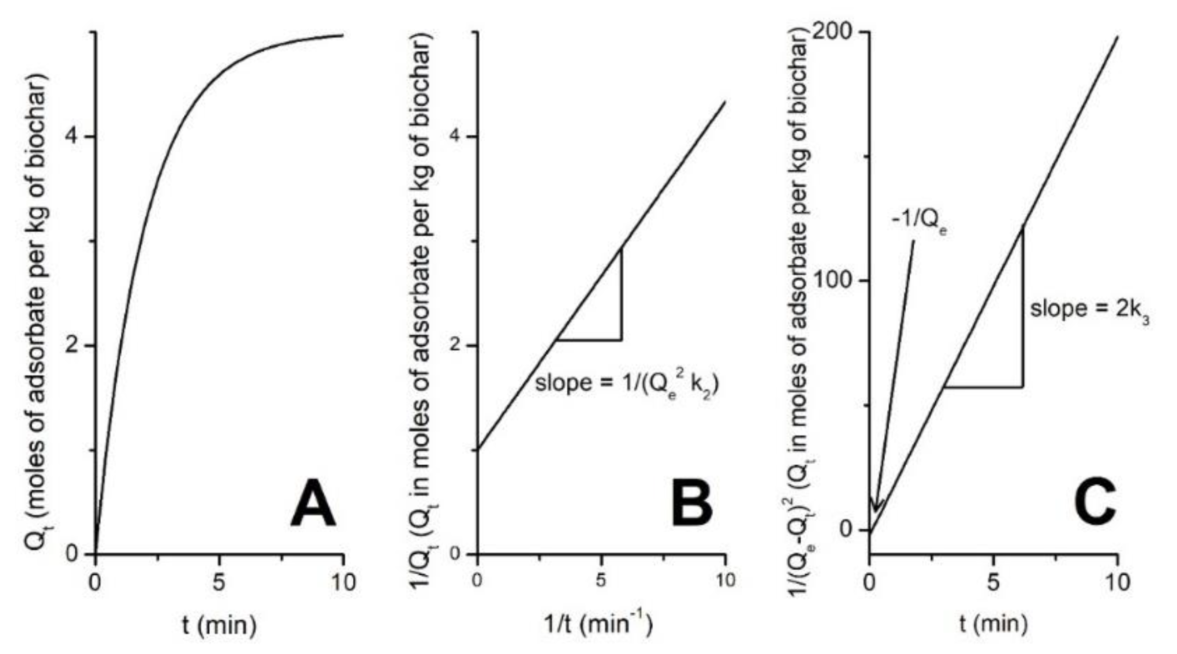
4.2. The Kinetics of Biochar Adsorption/Desorption

The reaction rate for the equilibrium described in Equation (10) is defined as the amount of adsorbate disappearing from the solution in the time unit as it is adsorbed on biochar [165]. According to Tong et al. [166], Equation (25) must be accounted for the time dependence of biochar adsorption:
dQ dt = k x ( Q e Q ) x
Here, Q is the amount (in moles) of adsorbate per mass unit (in kg) of biochar; Q e is the amount of adsorbate in solution when the sorption equilibrium is achieved (it can be expressed in moles per kilograms of solvent); x is the reaction order (it can have any value ≥ 0); k x is referred to as kinetic constant. The latter is used as the experimental parameter to establish the affinity between adsorbate and adsorbent. The larger the k x value, the higher the adsorbate-adsorbent affinity.
The order of reaction is experimentally established upon integration of Equation (25) and determines the dependence of the reaction rate on the concentration of the reactants. Assuming x = 1, 2, 3 after integration and rearrangement, Equation (25) can be re-written as in (26)–(28), respectively:
Q t = Q e ( 1 e k 1 t )
1 Q t = 1 + 1 Q e 2   ·   k 2   ·   1 t
1 ( Q e Q t ) 2 = 1 Q e + 2 k 3 t
Noticeably, for any x ≠ 1 (i.e., the order of reaction can assume also non-integer values), and the general solution of Equation (25) can be written as:
Q t = Q e [ Q e ( 1 x ) ( 1 x ) k x t ] 1 ( 1 x )
In all the previous equations, Q t is the amount of adsorbate per mass unit of biochar at time t , while k 1 , k 2 , and k 3 are the first-, second-, and third-order kinetic constants, respectively. Due to the complexity of the biochar adsorption phenomena (see below), these kinetics are also referred to as kinetics of pseudo-first, pseudo-second, and pseudo-third order, respectively [166,167,168,169,170,171,172].
Figure 12 reports the shape of Equations (26)–(28) which must be experimentally accounted for to establish if the adsorption follows one of the mentioned kinetic laws. Figure 12A shows how the fitting of the experimental data points should appear if the pseudo-first order kinetics applies. Conversely, Figure 12B,C report the linear correlation to be applied when the pseudo-second and pseudo-third order kinetics are valid.
Pseudo second-order kinetics appeared to best describe the adsorption uptake rate of a dye on biochar surface from rice husk [173], of Pb(II) and Cd(II) on the surface of a magnetic biochar obtained by functionalizing costless pine bark wastes with CoFe2O4 [174], and of Cu(II) and tetracycline on a Fe/Zn-doped sawdust biochar [175]. Interestingly, a study from Reguyal et al. [176] showed that the kinetics of biochar absorption is also affected by adsorbate concentration. It was reported that the pseudo-second order kinetic model best described the experimental data at low sulfamethoxazole concentrations (between 1 and 5.1 mg L−1), while the pseudo-first order best applied to the kinetic data when sulfamethoxazole concentration was as high as 20.5 mg L−1 [176]. However, it must be noticed that in recent kinetic studies, the terms pseudo first- and pseudo second-orders have been replaced by the term “partition coefficient” which better accounts for the biochar behavior in removing pollutants from environmental compartments [177,178,179,180].
The third-order kinetic model is rarely applied in biochar chemistry. However, Zahedifar and Moosavi [181] reported that it was unsuitable to explain the Zn desorption mechanisms from biochar-amended calcareous soils, while Tian et al. [182] showed that the third-order kinetics can be efficaciously used to describe the mechanisms of the CO2 gasification of Miscanthus-derived-biochar at different processing conditions.

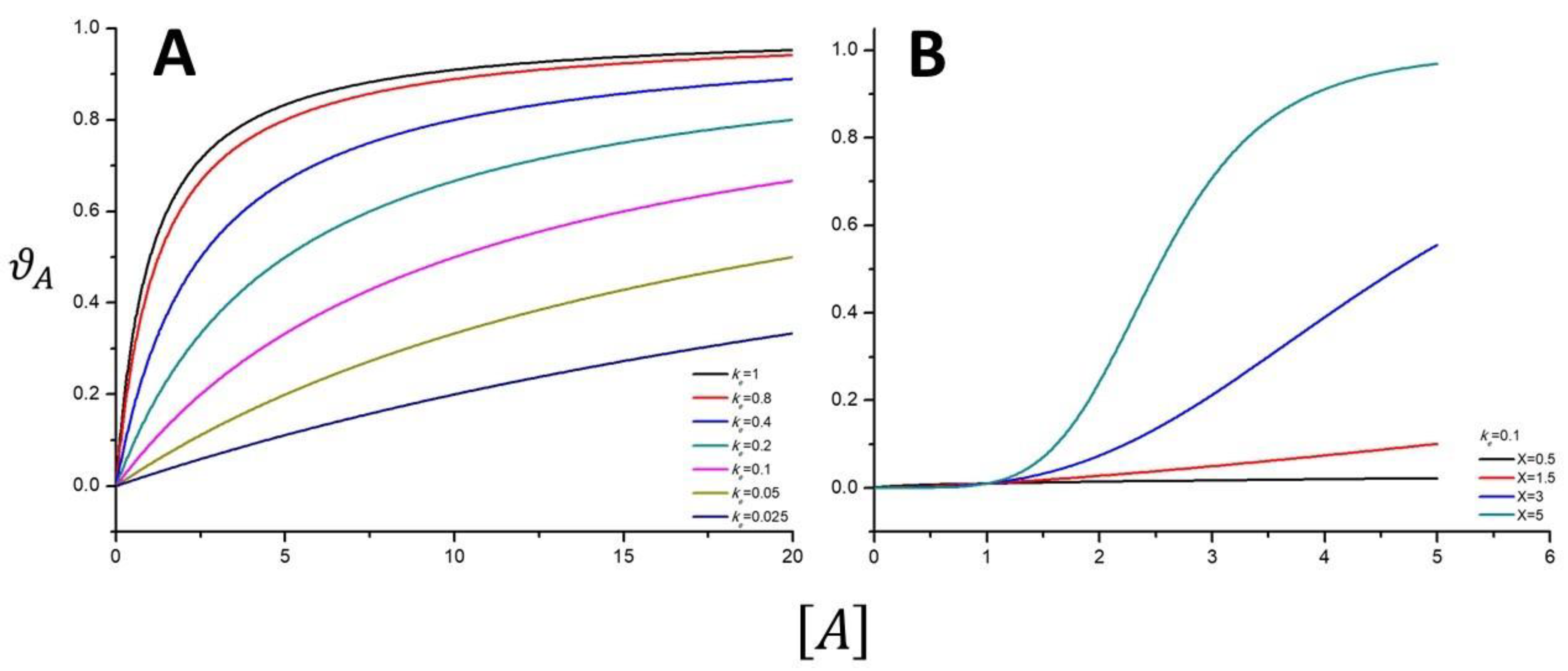
4.3. The Meaning of the Reaction Order and the Langmuir Isotherm from Kinetic Considerations

The reaction order is often related to the molecularity of a reaction. The term “molecularity” refers to the number of reactant molecules binding together to form, within the rate-limiting step of the reaction, an “activated complex” that affords the reaction products [165]. Accordingly, a first-order reaction is a reaction for which only one molecule among the different reactants is involved in the activated complex formation. However, when two molecules are needed to form the collision complex, the reaction can be referred to as second order. According to Laidler and Glasstone [165], reactions occurring on the surface of a solid-phase system, such as a catalyst, can be also considered as third-order reactions. In fact, the collision complex is made by all the reactants interacting with the surface of the catalyst. It must be recognized that the relationship between the order of a reaction and the molecularity is only a simplification. However, this can help in developing a simplistic adsorption theory such as the one elaborated by Langmuir at the beginning of the 20th century [183,184,185].
Let us indicate with the letter B the biochar, with the letter A the system that can be adsorbed on biochar, and with B1 the A–B complex containing a molar amount of adsorbate which interacts with the biochar surface. We can write the equilibrium reported in (30):
B + A B 1
where the left-to-right reaction is the adsorption of A on B, thereby providing B1, while the right-to-left reaction is the desorption of A from the B surface. Let us also assume:
(I)
a flat biochar surface;
(II)
each A molecule can interact with only one functional group on the biochar surface;
(III)
the A molecules can form only a monolayer on the biochar surface;
(IV)
the interactions of each A molecule are isotropic.
Based on these constraints, it is possible to consider the relationship (31) as descriptive for the steady-state condition:
r d = r i
where r d = k d [ A ] [ B ] is the second-order adsorption rate containing the adsorption kinetic rate constant ( k d ), the molar concentration of the adsorbate in solution as the equilibrium is achieved ( [ A ] ), and the molar concentration of the available adsorbing biochar sites at the equilibrium ( [ B ] ); while r i = k i [ B 1 ] is the first-order desorption rate containing the desorption kinetic rate constant ( k i ) and the adsorbate surface molar concentration ( [ B 1 ] ).
Being the total amount of adsorbing biochar sites given by [ B 0 ] = [ B ] + [ B 1 ] , the equilibrium constant for the Equation (29) given by k e = k d / k i and the fraction of biochar sites covered by the adsorbate given by ϑ A = [ B 1 ] / [ B 0 ] , it is straightforward to obtain Equation (32) which is the simplest form for the Langmuir adsorption isotherm.
ϑ A = k e [ A ] k e [ A ] + 1
Figure 13A reports the simulations of the Langmuir Equation (32) by using different k e values. When k e is raised up to 1, the trend changes from the quasi-linear behavior observed for low k e values (i.e., k e = 0.025 ) to the L-shaped one. Equation (32) is unreliable in fitting S-shaped experimental data. This is certainly due to the limits of the approach based on the ideal conditions (I) to (IV) indicated above. In fact, the ideal (I) to (IV) conditions are valid only for monodentate adsorbents in dilute solutions, while the biochar surface must be completely flattened. The latter condition is never a real situation.
A modified Langmuir isotherm to account for non-ideal conditions is given in Equation (33) [186]:
ϑ A = k e [ A ] X k e [ A ] X + 1
where X is an empirical parameter related to the effects of the adsorbate concentration. Equation (33) appears to be a good alternative to the model depicted in Equation (31) when S-shaped trends are acquired (Figure 13B). A slightly modified version of Equation (33) is referred to as the Sips equation [187,188], which can be written in the form (34):
q e = q max ( K e [ A ] ) X 1 + ( K e [ A ] ) X
Equation (34) has the advantage that the K e values are always expressed as L mol−1, irrespective of the value for X. Moreover, it reduces to the Freundlich equation for 1 ( K e [ A ] ) X . It is worth noting that Equation (34) has never been used in the evaluation of biochar adsorption properties. Therefore, it is desirable that in the future its suitability for the analysis of biochar characteristics is studied.
Notwithstanding the aforementioned limitations, the Langmuir model reported in Equation (31) showed a suitability to explain the competitive adsorption of different antibiotics on bamboo-derived biochar, whereas Freundlich isotherm was more reliable in modelling absorption of single antibiotics on the same biochar [189]. Similar results regarding the reliability of the Langmuir isotherm given in Equation (31) were obtained by Zhou et al. [175] who studied the adsorption mechanisms of Cu(II) on a Fe/Zn-doped-biochar.
As a general remark, special attention must be paid when one considers studies concerning the use of the Langmuir models. In most of the published papers, volumetric concentrations of adsorbate are commonly used without any theoretical background. Conversely, the concentration units must be mol L−1. This comes from thermodynamic considerations [190]. In fact, Liu [190] showed that incorrect and unreasonable G 0 values can be calculated when non-molar units are applied. As a consequence, misunderstanding of the adsorption/desorption mechanisms can occur [190].

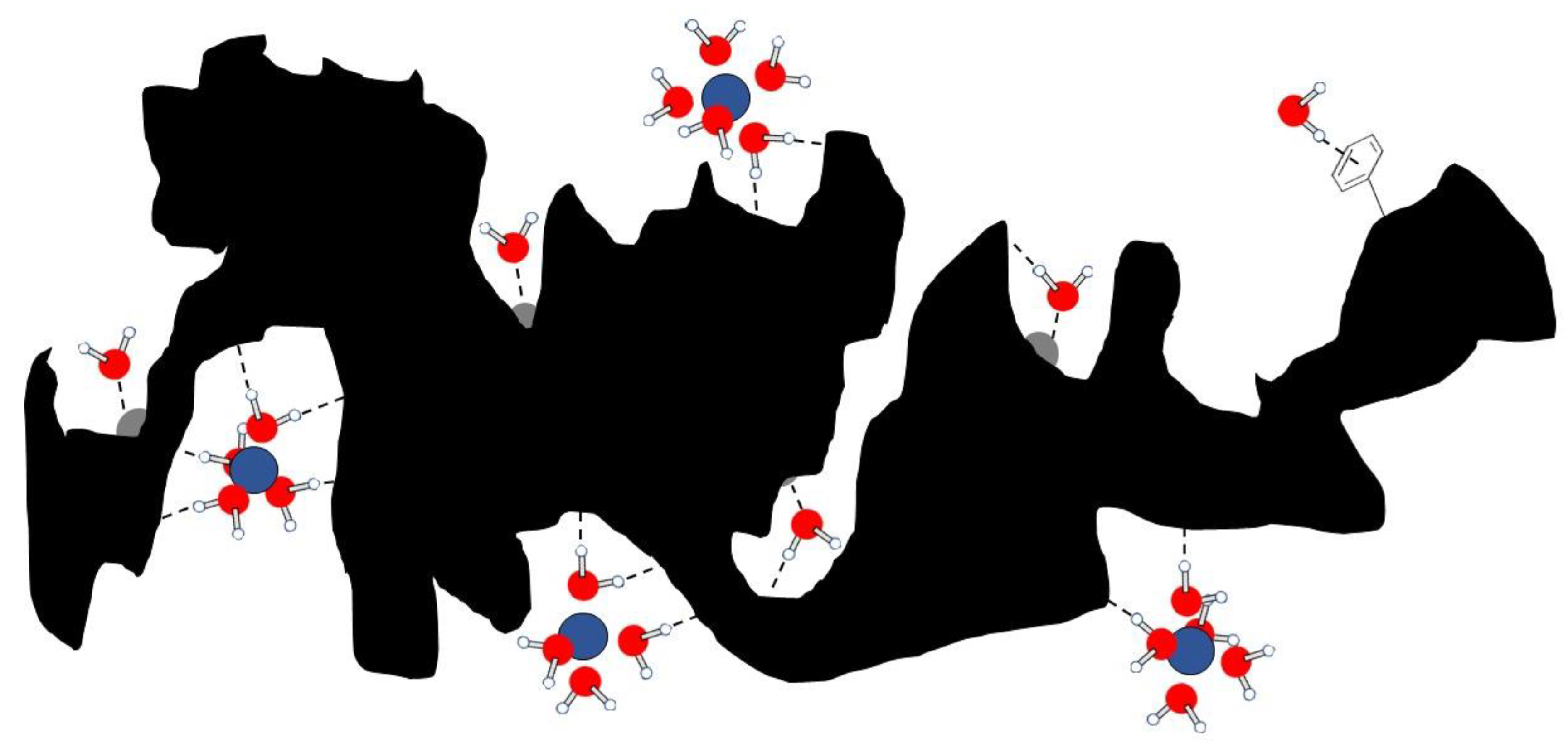
4.4. The Dynamics of Water and Nutrients in Biochar Pore System

In the previous paragraphs, the traditional thermodynamic and kinetic approaches have been discussed to explain how experimental data can be handled to understand how strongly an adsorbate is bound to biochar and which possible molecular mechanisms can be involved in the adsorbate–biochar interactions. However, a quite innovative dynamic approach can be used to understand the nature of the adsorbate–biochar interface interactions. This is based on the evaluation of fast field cycling (FFC) NMR relaxometry investigations [163,164].
Fast field cycling NMR relaxometry has been specifically designed for the measurement of the longitudinal relaxation times (T1) of NMR observable spin nuclei [163,164,191,192]. T1 is a measure of the time needed for the recovery of the longitudinal component of the magnetization along the z-axis [193]. Its value is influenced by:
“fluctuating local magnetic or electrical fields generated by (i) nuclear dipoles, (ii) unpaired electrons, (iii) electric charges interacting with nuclear quadrupole moments for > 1/2 spin nuclei, (iv) anisotropy of the chemical shielding tensor, and (v) fluctuating scalar coupling interactions and molecular rotations. It is recognized that molecular motions are the primary factors affecting the aforementioned fluctuations. For this reason, the measurement of longitudinal relaxation time (or longitudinal relaxation rate, R1, that is the inverse of T1) can be related to molecular dynamics. In particular, FFC NMR relaxometry allows evaluating motion frequencies ranging from ≈105 to ≈108 Hz. These are the typical motion frequencies for aqueous systems in natural porous media” [194].
It is widely recognized that the molecular dynamics investigated by the T1 value measurements of liquid systems, such as water, in biochar pores is affected by the interactions with the porous boundaries [163,164,191,192,193,194,195,196]. Namely, the smaller the pore size, the more constrained water molecules are. Conversely, when pore sizes increase, water molecules become more mobile. For this reason, according to pore size distribution, three different water types can be recognized: (i) strongly bound water in micropores; (ii) weakly bound water in mesopores; (iii) bulk water in macropores [163].
Following variable temperature FFC NMR relaxometry experiments [22], it was shown that water molecules can interact with pore boundaries by the inner-sphere mechanism, thereby suggesting that water molecules penetrate into biochar pores and adhere to the surface by formation of weak bonds such as non-conventional H-bonds (e.g., the OH–π bonding described in References [197,198]), Van der Waals interactions, and coordination linkages (Figure 14). The latter are Lewis acid–base interactions occurring when the electron-rich oxygen in water approaches the metal ions situated on the biochar surface.
It is worth noting that the water molecules in biochar pores belong also to the hydration spheres of solutes which may work as plant nutrients (Figure 14) [199,200]. In other words, some plant nutrients are captured in biochar thanks to water-mediated interactions and can be released into the soil solution when it is used as soil amendment [17,18,19].
Given that the nature of the aforementioned interactions is transient, it is possible to state that the movement of nutrients in the biochar pore system can occur via two different mechanisms [201]. Firstly, water molecules diffuse horizontally on the biochar surface. This allows nutrients to be dragged towards plant roots. Secondly, each water molecule can “hop” from the biochar surface over a longer distance, while it is replaced by another molecule. This allows nutrients to be leached towards deeper soil horizons, thereby reducing fertility of the upper soil horizons. The time spent by water (and hence water-solvated nutrients) either on the biochar surface (surface–time) or in the bulk (bulk–time) can be measured by FFC NMR relaxometry [195]. The relationship between the surface– and the bulk–times was used to define the biochar wettability [195], which is affected by the chemistry of the biochar surface. The latter, in turn, depends on all the experimental conditions reported above for the preparation.
Having clarified the molecular mechanisms involved in the water/nutrient dynamics inside the biochar pore system, it is intuitive to understand why biochar application to soils increases water retention [16,202,203,204,205], thereby ameliorating physiological plant responses to drought stresses [206], enhancing plant defense mechanisms [207], and increasing soil microbial biodiversity [208,209]. For further information about the advantages and disadvantages of biochar applications, see Das et al. [210].

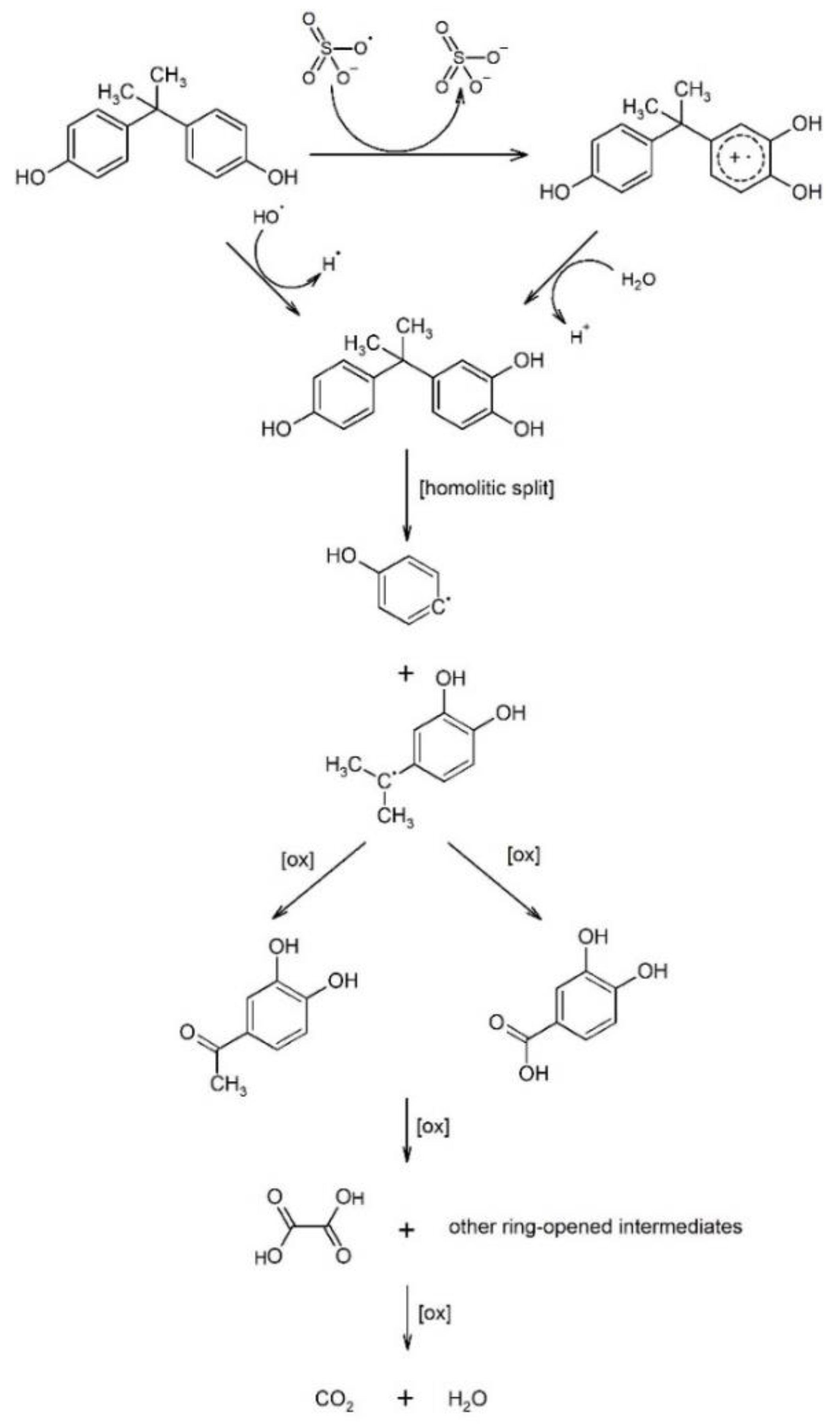
4.5. The Mechanisms of Entrapment and Decomposition of Pollutants in Biochar

In Section 3.4., a post-pyrolysis biochar functionalization with persulfate was described. It was pointed out that persulfate activates biochar surface via formation either of radical sulfate ( · SO 4 ) or hydroxyl radical ( · OH ). When the persulfate-activated biochar traps pollutants, a reaction such as that described in Figure 15 for the degradation of bisphenol A, occurs [138]. Namely, this pollutant (also known as 2,2′-bis-(4-hydroxyphenil)-propane) is firstly oxidized to 2-(4-hydroxyphenil)-2′-(3,4-dihydroxyphenil)-propane. Then a homolytic split occurs, generating hydroxyphenyl and 2-(3,4-dihydroxyphenyl)-propane radicals. Both are subjected to a series of not well-defined oxidations which result in the formation of carbon dioxide and water [138].
When the biochar is obtained by co-pyrolysis with polyethylene terephthalate (Section 3.3.7), a material very efficient in removing/entrapping organic and inorganic pollutants is obtained [135]. In particular, Oh and Seo [135] reported that this type of biochar is able to reduce selenate ( SeO 4 ) to selenite ( SeO 3 ) and then to selenide ( Se 2 ) via metallic selenium (Se) by redox reactions that can be schematized as follows:
2 SeO 4 + C 2 SeO 3 + CO 2
4 SeO 3 + 5 C + 4 H + 4 Se + 5 CO 2 + 2 H 2 O
2 Se + C + 2 H 2 O 2 Se 2 + CO 2 + 4 H +
In reactions (35) to (37), C represents the biochar which is oxidized to carbon dioxide. However, biochar oxidation can also be limited to a surface functionalization with formation of oxidized groups, thereby making the carbonaceous material more hydrophilic. While selenium-containing pollutants are immobilized by the alteration of their oxidation state, a pollutant such as chromate ( CrO 4 2 ) is trapped via a mechanism involving electrostatic interactions [135]. Experimental results [135] suggest that the presence of polyethylene–terephthalate (Section 3.5.2.) as co-pyrolyzing material allows formation of a biochar where the graphitic-like layer may reveal domains with low electron density. Hence, the electron-rich chromate anions can be hooked in the electronic “holes”, thus allowing formation of stable complexes which can be easily removed and disposed of in landfills. Conversely, when heavy metals ( Me n + ), such as Pb 2 + , are present in the environment, a C π Me n + mechanism must be invoked. In this case, the electron-rich aromatic systems of the graphitic-like biochar moieties (i.e., C π ) can “hook” the electron-poor metal cations [135]. However, Paz-Ferreiro et al. [211] report that the mechanisms for heavy metal entrapment in biochar are also due to the presence of surface oxygenated/nitrogenated functions, which can “hook” the metals via their lone-pair electrons. For this reason, the same authors state that biochar is suitable for soil phytoremediation projects because it allows reduction of heavy metals leachability and bioavailability. As already discussed in Section 3.3.6., biochar affinity for metal ions can be beneficial for water treatment. Surface complexation was found to be the main mechanism in Pb2+ removal from contaminated water in lab-scale flow-through column tests [212], where biochar potential as an active component in permeable reactive barriers for groundwater treatment was assessed.
Aromatic pollutants, such as 2,4-dichlorophenol (DCP) and triazines, may interact with the biochar via weak C π C π interactions [137,162], which were also described in Conte et al. [213] to explain the increased retention of polycyclic aromatic hydrocarbons in soils induced by treatment with humic substances. As nitro-groups are bound to the benzene ring, such as in the case of the 2,4-dinitrotoluene, the biochar C π systems can trap the aforementioned pollutant via interactions with the π systems of the nitro-groups [135]. Different mechanisms were accounted for to explain the immobilization of polyfluorinated organic compounds on biochar surfaces [200]. In particular, a cooling agent used in scientific instruments commercially known as Galden®—IUPAC name is oxidized poly(1,1,2,3,3,3-hexafluoroprop-1-ene)—with formula CF 3 ( OCF ( CF 3 ) CF 2 ) n ( OCF 2 ) m OCF 3 and an average molecular weight of 610 Da, can be adsorbed on biochar’s surface by (i) charge transfer bond with biochar metal impurities; (ii) H-bonds with biochar surface hydrophilic groups; (iii) Van der Waals interactions with the biochar C-skeleton; (iv) outer-sphere interactions where water molecules bridge the Galden® with the electron-poor biochar metal impurities. Biochar can also trap anionic pollutants such as fluoride ( F ) in groundwater [214]. In this case, the presence of biochar surface cation impurities is considered responsible for F electrostatic entrapment. However, the effect of these impurities reduces as pH increases. In fact, Zhou et al. [214] observed that the higher the pH, the lower the amount of fluoride retained on the biochar surface. This can be explained by the progressive deprotonation of the surface acidic functional groups which allow negative charge to increase and electrostatic repulsions. In addition, when magnetic biochars are applied for groundwater remediation, the presence of paramagnetic systems modifies biochar z-potential, thus allowing enhancement of the capacity of magnetic biochar surfaces to attract fluoride ions [214].

5. Conclusions

This paper aimed for a critical evaluation of the main literature dealing with the physical chemistry of biochar. As stated in the introduction, the number of studies on biochar applications in many fields is increasing tremendously. While concordance about biochar peculiarities exists in all the chemistry sectors where this system is seen as the base for the synthesis of many different materials (e.g., filters, electrodes) [215], debate regarding biochar’s usefulness in environmental applications is ongoing [28]. The latter is due to the fact that in many studies, biochar is used prior to any detailed chemical and physical evaluation of its properties and analysis of its environmental impact [216].
Summarizing the purpose of this paper in a very few words, it is a guide to answer the key question on how I intend to use the biochar.
We have reached an awareness about biochar complexity. This paper highlights that a great deal is known about the basis of biochar chemistry and physics, although the answers that have been reported here represent the starting point for new questions.
Certainly, one should be aware that biochars made from different feedstocks can have very different chemical properties, even if the same process is applied to produce them. However, not only feedstock choice but also biomass pre-functionalization, the correct production method, and biochar post-functionalization can be considered key points for biochar uses. Accordingly, papers where any conclusion (either positive or negative) regarding biochar is achieved without any deep chemical–physical investigation are not acceptable anymore. Moreover, the reading of the oldest papers where no physical–chemical analyses are reported should be contextualized and conclusions revisited by reproducing the same data after performing the correct investigations to understand the “why and how” behind those conclusions.

Author Contributions

All the authors equally contributed to this paper. All authors have read and agreed to the published version of the manuscript.

Funding

This research received no external funding.

Institutional Review Board Statement

Not applicable.

Informed Consent Statement

Not applicable.

Data Availability Statement

Not applicable.

Conflicts of Interest

The authors declare no conflict of interest.

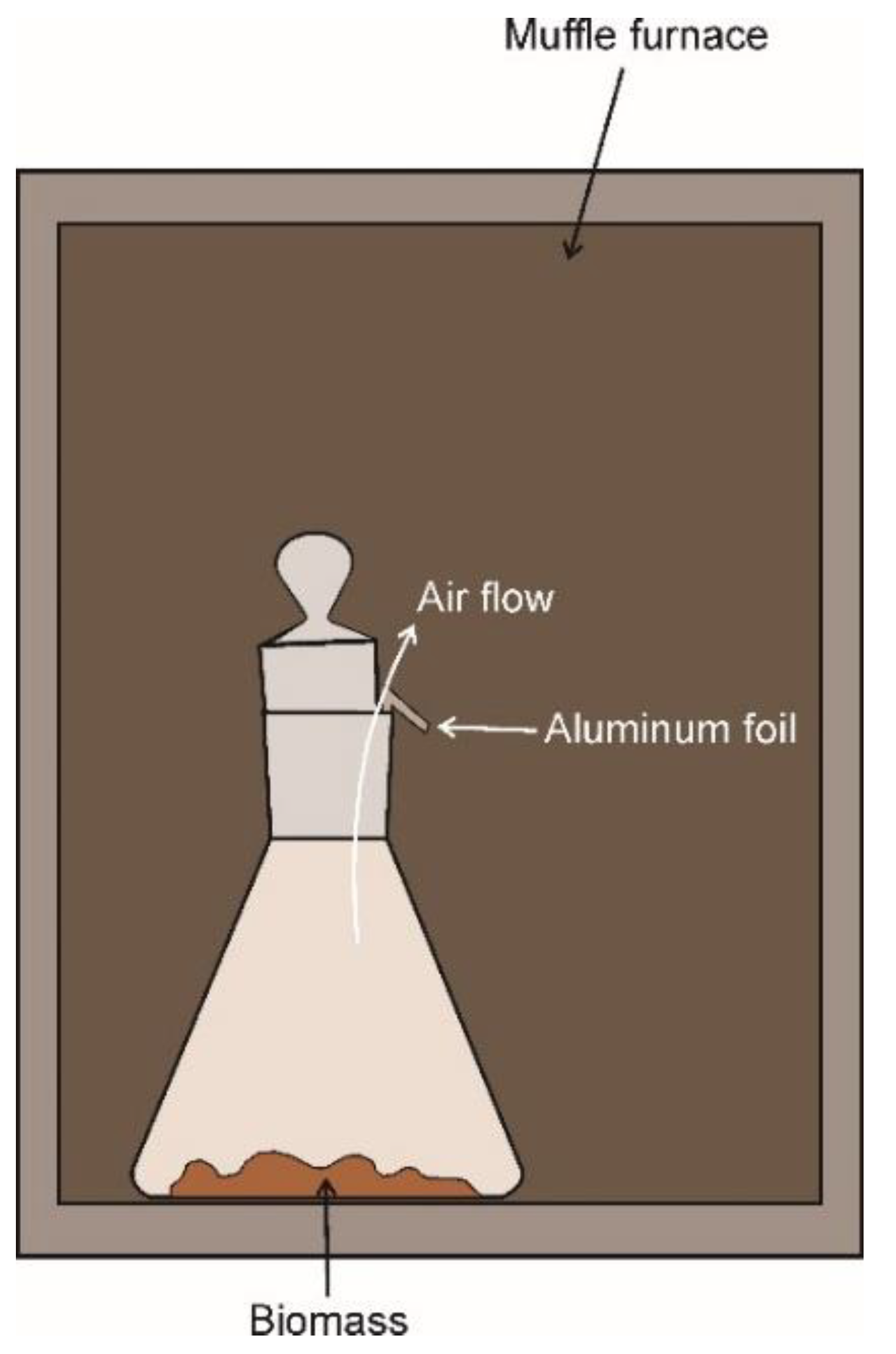
Appendix A. The Lab–Muffle–Furnace Method

When only a few grams of biochar are needed either for the purpose of chemical–physical characterization or in vitro experiments to test biochar effects on seed germination and plant growth; a lab production can be achieved by using the system reported in Figure A1 [77]. Namely, a small amount of an air-dried biomass is weighed in a Pyrex flask and placed into a muffle furnace with a cap not-hermetically closed on it. This can be obtained by placing an aluminum foil straw between the cap and the Pyrex flask opening. Muffle furnace temperature is then slowly raised until the desired value is reached. Temperature increase must be slow to avoid rapid gas release and sample blow-up. Initially, residual air is still present in the system. As the reaction starts, oxygen is consumed, the air flows away from the small aperture and cannot re-enter the flask due to the high operating temperature. Once this occurs, the thermal degradation proceeds under anoxic conditions. The limit of this method is not only the very low amount of biochar that can be obtained, but also the impossibility of controlling the quenching procedure. Moreover, the temperature is manually ramped, unless the lab muffle furnace is provided with an automatic temperature ramp controller.
Figure A1. Lab–muffle–furnace biochar production. A few grams of air-dried biomass are placed in a Pyrex flask. The temperature is slowly raised to the desired value. Initially, the oxygen-containing air is still in the flask. Once the oxygen is consumed and the gas flows out from the container, the pyrolysis starts.
Agronomy 11 00615 g0a1

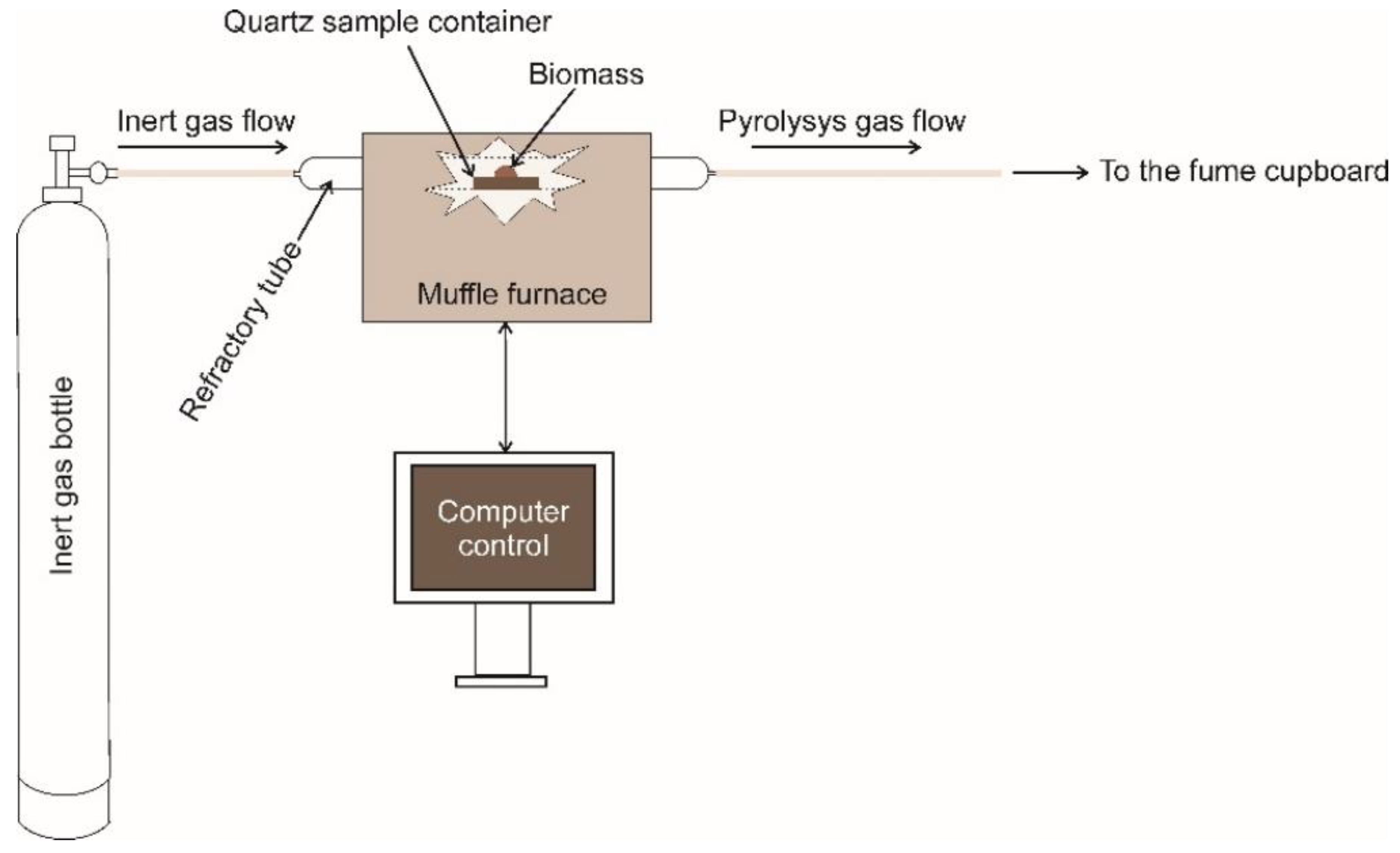
Appendix B. The Lab Pyrolizer

The biochar obtained by lab–furnace method (Appendix A) cannot be used for the production of new materials such as electrodes [67], sorbent for specific pollutants [68], or medicine [49]. In these cases, reproducible chemical–physical properties must be achieved by controlling all the pyrolysis conditions. Therefore, a different production approach must be utilized [67,68,217].
Figure A2 shows a typical lab pyrolizer made from a computer-controlled muffle furnace and a refractory tube where the biomass sample placed in a quartz container is positioned. The refractory tube is connected to an inert gas bottle. The inert gas fulfills two functions. Firstly, it removes the oxygen-containing air from the refractory tube, thereby allowing a pyrolysis with a yield larger than that from the lab muffle furnace methods (Appendix A). Secondly, the inert gas works as a carrier to remove the volatile pyrolysis by-products which are expelled towards the fume cupboard. The computer control allows to program the temperature ramp, the pyrolysis temperature, and the pyrolysis duration. The advantage of the lab pyrolizer reported in Figure A2 is the possibility of a scaling up for industrial purposes [217], while the limit can be the consumption of huge amounts of expensive inert gases.
Figure A2. Lab pyrolizer. The muffle furnace is controlled by a computer which allows the programming and control of the temperature ramp to reach the pyrolysis temperature. An inert gas removes the air from the systems, thus allowing biomass thermal degradation with a larger yield than by the lab muffle furnace method. The reported scheme represents the one available in one of the authors’ lab (PC).
Agronomy 11 00615 g0a2

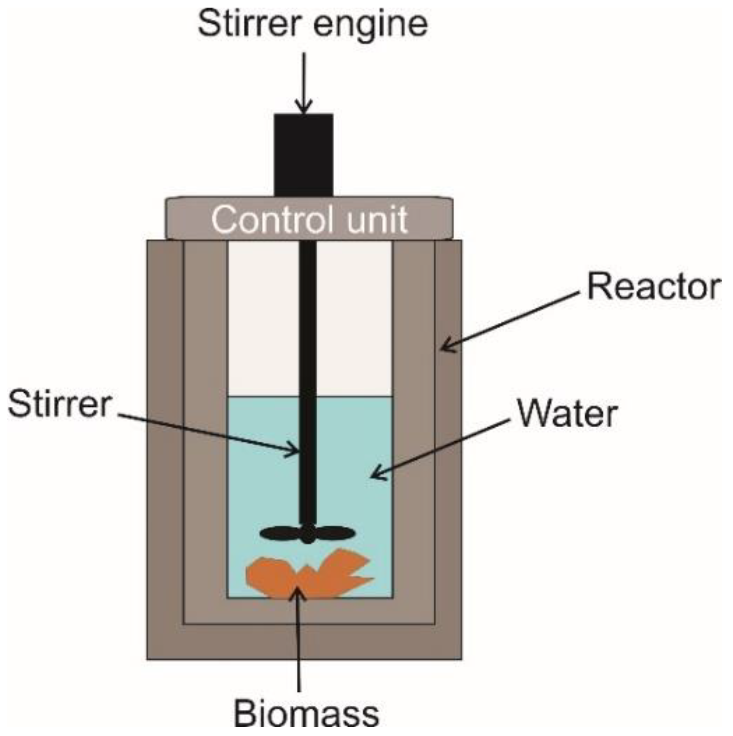
Appendix C. The Hydrothermal Carbonization

Instead of the pyrolysis conducted as aforementioned, a newer way to produce biochar is the hydrothermal carbonization (HTC) (Figure A3). It is performed in a reactor where the biomass, fully immersed in water, is heated at high pressure at a temperature between 150 °C and 350 °C [218]. Under these conditions, water causes the hydrolysis and cleavage of lignocellulose as well as the hydrolysis of all the organic systems present in the biomass [218]. An advantage of HTC is the consumption of a lower amount of thermal energy as compared to pyrolysis, while its limit is the impossibility to precisely control the operating pressure. The latter “depends on the steam pressure of water and gas development during feedstock decomposition” [218,219]. Usually, to distinguish between the biochar obtained by pyrolysis and that produced by HTC, this second is referred to as “hydrochar” [218].
Figure A3. Schematic representation of a reactor for the hydrothermal carbonization of biomasses.
Agronomy 11 00615 g0a3

Appendix D

As stated in the present study, biochar is obtained by the thermal degradation of biomasses in oxygen starved conditions. One of the most used and economic technologies for biochar achievement is the Kon-Tiki kiln depicted in Figure A4A, while the reactions occurring during biochar production are reported in Figure A4B [30,72].
The Kon Tiki kiln consists of a metallic cone where woody biomass, having the characteristics reported in Table 1, is placed and rested on a metallic grid. The thermal energy needed for the pyrolysis is provided by the flame produced by triggering biomass combustion. Once the burning starts, a series of different thermal events occur (Figure A4B). As the temperature rises to 100 °C, biomass moisture is volatilized. Simultaneously wood combustion triggers, thereby producing carbon dioxide, ashes, and water vapor as well as an increase of thermal energy. As the temperature rises, the oxygen around the wood disperses and the production of oil vapors, pyrolysis gases (e.g., CO, H2, CH4), and biochar is obtained in a zone where a temperature of around 400 °C is reached. Oil vapors disperse and are degraded to hydrocarbons and tar in the zone of the flame where the temperature rises to around 600 °C. The soot deriving from these processes is decomposed in the zone where the temperature reaches around 1500 °C. Finally, the most distant part of the flame contains all the degradation products at a temperature of around 400 °C.
To prevent an over production of ashes with a biochar low yield, the reactions occurring in the Kon Tiki kiln can be quenched by using different methods. As an example, the quench can be achieved with water solutions (such as tap water or urine) or by smothering with a 5–10 cm thick layer of soil, sand, or manure [30,72].
Figure A4. The Kon Tiki kiln is the metal funnel represented in (A). Here, the woody biomass is placed and burned. During the burning, the reactions described in (B) occur, thereby leading to the production of biochar. The image of the Kon Tiki kiln was modified from https://www.biochar-journal.org/en/ct/39 (accessed on 21 March 2021), while the image of the reactions was adapted from http://www.allpowerlabs.com/gasification-explained (accessed on 21 March 2021).
Agronomy 11 00615 g0a4
Soil, sand, and manure are applied on the upper part of the kiln and act by reducing the presence of the oxygen feeding the fire. This type of heating extinction is very slow and may produce a biochar rich in condensates and pollutants such as PAHs. The final carbonaceous product can certainly be good as fuel charcoal because condensates and PAHs burn well. However, it cannot be applied for agricultural purposes due to the possibility of groundwater contamination [30].
When water or an aqueous solution is used, the quenching can be achieved in two different ways. The liquid can be applied from the bottom. In this case a hot steam is generated when the solution gets in contact with the hot surface of the pyrolyzing material and two effects are obtained: (i) an increase of the biochar surface area, thereby improving its adsorption properties, (ii) the aqueous solution expels and reacts with the condensates from the pores of the biochar, thus preventing their possible contaminating effect [30,72]. If the quenching is done from the top of the kiln, the effect of the hot steam is not as efficient as previously described because the vapor phase cannot soak the whole system. As a consequence, a reduced surface area with a diminished adsorption potential is obtained [30,72]. The advantage of the Kon Tiki kiln is the huge amount of biochar that can be obtained, thereby fulfilling the need for field applications. The limitation is the impossibility of controlling all the pyrolysis conditions. This leads to biochars with chemical–physical properties which may differ case by case. Therefore, a precise analytical characterization is needed prior to any possible biochar field use.

Appendix E

Assuming that the conditions reported in Table 1 are fulfilled, the carbonaceous material obtained as a by-product of industrial thermochemical processes (i.e., gasification) can be also be referred to as “biochar” [99]. Gasification is used to produce a syngas which is in turn applied for energy purposes. The process has been detailed in De Pasquale et al. [99] and references therein. Briefly, the biomass is placed in a reactor where it is partially oxidized by heating at temperatures as high as 1200 °C. The syngas produced by the biomass thermal degradation consists of a mixture of carbon monoxide, carbon dioxide, hydrogen, methane, and nitrogen. It can be used to power diesel-cycle endothermic engines to produce both electricity and heat or as a ready-to-use fuel. The major reactions occurring during gasification are [220]:
Drying:
H 2 O ( l ) H 2 O ( g )   ( H = 40   MJ   kmol 1 )
Combustion
2 C + O 2 2 CO   ( H = 111   MJ   kmol 1 )
2 CO + O 2 2 CO 2   ( H = 283   MJ   kmol 1 )
2 H 2 + O 2 2 H 2 O   ( H = 242   MJ   kmol 1 )
Gasification
C + H 2 O CO + H 2   ( H = 131   MJ   kmol 1 )
C + CO 2 2 CO   ( H = 172   MJ   kmol 1 )
C + 2 H 2 CH 4   ( H = 75   MJ   kmol 1 )
CO + H 2 O CO 2 + H 2   ( H = 41   MJ   kmol 1 )
CH 4 + H 2 O CO 2 + 3 H 2   ( H = 206   MJ   kmol 1 )
The total amount of thermal energy from these processes is ΔH = −203 MJ kmol−1. However, biomasses contain not only carbon, hydrogen, and water but also nitrogen (which is converted to NxOy, NH3, and N2), sulphur (converted to H2S), and chlorine (converted to HCl). The amount of nitrogenated, sulphurated, and chlorinated gases in syn-gas is negligible. Finally, the many inorganic components usually present in biomasses are collected as ashes together with the biochar (Figure A5).
Figure A5. The left side of the photo shows conifer wood residues. The right side shows the biochar obtained by the conifer biomass after industrial thermochemical carbonization (i.e., gasification). The conifer biochar showed here was analyzed in de Pasquale et al. [99]. The amount of ash resulted 80 ± 7 g kg−1.
Agronomy 11 00615 g0a5

References

  1. Karl, T.R.; Trenberth, K.E. Modern Global Climate Change. Science 2003, 302, 1719–1723. [Google Scholar] [CrossRef] [Green Version]
  2. Brown, B.J.; Hanson, M.E.; Liverman, D.M.; Merideth, R.W. Global sustainability: Toward definition. Environ. Manag. 1987, 11, 713–719. [Google Scholar] [CrossRef]
  3. Qadeer, S.; Anjum, M.; Khalid, A.; Waqas, M.; Batool, A.; Mahmood, T. A Dialogue on Perspectives of Biochar Applications and Its Environmental Risks. Water. Air. Soil Pollut. 2017, 228, 228–281. [Google Scholar] [CrossRef]
  4. Zhang, L.; Charles, C.; Champagne, P. Overview of recent advances in thermo-chemical conversion of biomass. Energy Convers. Manag. 2010, 51, 969–982. [Google Scholar] [CrossRef]
  5. Mićić, V.; Jotanović, M. Bioethanol as fuel for internal combustion engines. Zast. Mater. 2015, 56, 403–408. [Google Scholar] [CrossRef]
  6. Solarte-Toro, J.C.; Chacón-Pérez, Y.; Cardona-Alzate, C.A. Evaluation of biogas and syngas as energy vectors for heat and power generation using lignocellulosic biomass as raw material. Electron. J. Biotechnol. 2018, 33, 52–62. [Google Scholar] [CrossRef]
  7. Mackaluso, J. The use of syngas derived from biomass and waste products to produce ethanol and hydrogen. Microbiol. Mol. Genet. 445 Basic Biotechnol. eJ. 2007, 3, 98–103. [Google Scholar]
  8. Cha, J.S.; Park, S.H.; Jung, S.C.; Ryu, C.; Jeon, J.K.; Shin, M.C.; Park, Y.K. Production and utilization of biochar: A review. J. Ind. Eng. Chem. 2016, 40, 1–15. [Google Scholar] [CrossRef]
  9. Lehmann, J.; Gaunt, J.; Rondon, M. Bio-char sequestration in terrestrial ecosystems—A review. Mitig. Adapt. Strateg. Glob. Chang. 2006, 11, 403–427. [Google Scholar] [CrossRef]
  10. Novak, J.M.; Busscher, W.J.; Laird, D.L.; Ahmedna, M.; Watts, D.W.; Niandou, M.A.S. Impact of biochar amendment on fertility of a southeastern coastal plain soil. Soil Sci. 2009, 174, 105–112. [Google Scholar] [CrossRef] [Green Version]
  11. Dieguez-Alonso, A.; Anca-Couce, A.; Frišták, V.; Moreno-Jiménez, E.; Bacher, M.; Bucheli, T.D.; Cimò, G.; Conte, P.; Hagemann, N.; Haller, A.; et al. Designing biochar properties through the blending of biomass feedstock with metals: Impact on oxyanions adsorption behavior. Chemosphere 2019, 214, 743–753. [Google Scholar] [CrossRef] [PubMed]
  12. Spokas, K.A.; Reicosky, D.C. Impacts of sixteeen different biochars on soil greenhouse gas production. Ann. Environ. Sci. 2009, 3, 179–193. [Google Scholar]
  13. Lenton, T.M. The potential for land-based biological CO2 removal to lower future atmospheric CO2 concentration. Carbon Manag. 2010, 1, 145–160. [Google Scholar] [CrossRef] [Green Version]
  14. Yuan, J.H.; Xu, R.K.; Wang, N.; Li, J.Y. Amendment of Acid Soils with Crop Residues and Biochars. Pedosphere 2011, 21, 302–308. [Google Scholar] [CrossRef]
  15. Uchimiya, M.; Wartelle, L.H.; Klasson, K.T.; Fortier, C.A.; Lima, I.M. Influence of pyrolysis temperature on biochar property and function as a heavy metal sorbent in soil. J. Agric. Food Chem. 2011, 59, 2501–2510. [Google Scholar] [CrossRef]
  16. Baiamonte, G.; De Pasquale, C.; Marsala, V.; Cimò, G.; Alonzo, G.; Crescimanno, G.; Conte, P. Structure alteration of a sandy-clay soil by biochar amendments. J. Soils Sediments 2015, 15, 816–824. [Google Scholar] [CrossRef]
  17. Kammann, C.I.; Schmidt, H.-P.; Messerschmidt, N.; Linsel, S.; Steffens, D.; Müller, C.; Koyro, H.-W.; Conte, P.; Stephen, J. Plant growth improvement mediated by nitrate capture in co-composted biochar. Sci. Rep. 2015, 5, 11080. [Google Scholar] [CrossRef]
  18. Hagemann, N.; Joseph, S.; Schmidt, H.P.; Kammann, C.I.; Harter, J.; Borch, T.; Young, R.B.; Varga, K.; Taherymoosavi, S.; Elliott, K.W.; et al. Organic coating on biochar explains its nutrient retention and stimulation of soil fertility. Nat. Commun. 2017, 8, 1089. [Google Scholar] [CrossRef]
  19. Joseph, S.; Kammann, C.I.; Shepherd, J.G.; Conte, P.; Schmidt, H.-P.; Hagemann, N.; Rich, A.M.; Marjo, C.E.; Allen, J.; Munroe, P.; et al. Microstructural and associated chemical changes during the composting of a high temperature biochar: Mechanisms for nitrate, phosphate and other nutrient retention and release. Sci. Total Environ. 2018, 618, 1210–1223. [Google Scholar] [CrossRef] [Green Version]
  20. Tang, J.; Zhu, W.; Kookana, R.; Katayama, A. Characteristics of biochar and its application in remediation of contaminated soil. J. Biosci. Bioeng. 2013, 116, 653–659. [Google Scholar] [CrossRef]
  21. Mohan, D.; Pittman, C.U.; Steele, P.H. Pyrolysis of wood/biomass for bio-oil: A critical review. Energy Fuels 2006, 20, 848–889. [Google Scholar] [CrossRef]
  22. Conte, P.; Marsala, V.; De Pasquale, C.; Bubici, S.; Valagussa, M.; Pozzi, A.; Alonzo, G. Nature of water-biochar interface interactions. GCB Bioenergy 2013, 5. [Google Scholar] [CrossRef] [Green Version]
  23. Caporale, A.G.; Pigna, M.; Sommella, A.; Conte, P. Effect of pruning-derived biochar on heavy metals removal and water dynamics. Biol. Fertil. Soils 2014, 50. [Google Scholar] [CrossRef] [Green Version]
  24. Ahmad, M.; Upamali, A.; Eun, J.; Zhang, M.; Bolan, N.; Mohan, D.; Vithanage, M.; Soo, S.; Sik, Y. Chemosphere Biochar as a sorbent for contaminant management in soil and water: A review. Chemosphere 2014, 99, 19–33. [Google Scholar] [CrossRef] [PubMed]
  25. Schmidt, H.P.; Hagemann, N.; Draper, K.; Kammann, C. The use of biochar in animal feeding. PeerJ 2019, 7, e7373. [Google Scholar] [CrossRef] [Green Version]
  26. Idrees, M.; Jeelani, S.; Rangari, V. Three-Dimensional-Printed Sustainable Biochar-Recycled PET Composites. ACS Sustain. Chem. Eng. 2018, 6, 13940–13948. [Google Scholar] [CrossRef]
  27. Bi, Z.; Kong, Q.; Cao, Y.; Sun, G.; Su, F.; Wei, X.; Li, X.; Ahmad, A.; Xie, L.; Chen, C.M. Biomass-derived porous carbon materials with different dimensions for supercapacitor electrodes: A review. J. Mater. Chem. A 2019, 7, 16028–16045. [Google Scholar] [CrossRef]
  28. Conte, P.; Schmidt, H.-P.; Cimò, G. Research and Application of Biochar in Europe. In Agricultural and Environmental Applications of Biochar: Advances and Barriers; Guo, M., He, Z., Uchimiya, S.M., Eds.; Soil Science Society of America, Inc.: Madison, WI, USA, 2015; pp. 409–422. ISBN 9780891189640. [Google Scholar]
  29. Gezahegn, S.; Sain, M.; Thomas, S. Variation in Feedstock Wood Chemistry Strongly Influences Biochar Liming Potential. Soil Syst. 2019, 3, 26. [Google Scholar] [CrossRef] [Green Version]
  30. Schmidt, H.-P.; Taylor, P. Kon-Tiki Flame Curtain Pyrolysis for the Democratization of Biochar Production. Available online: http://www.biochar-journal.org/itjo/media/doc/1437139451142.pdf (accessed on 15 June 2020).
  31. Ogawa, M.; Okimori, Y.; Takahashi, F. Carbon sequestration by carbonization of biomass and forestation: Three case studies. Mitig. Adapt. Strateg. Glob. Chang. 2006, 11, 429–444. [Google Scholar] [CrossRef]
  32. Laird, D.A. The charcoal vision: A win-win-win scenario for simultaneously producing bioenergy, permanently sequestering carbon, while improving soil and water quality. Agron. J. 2008, 100, 178–181. [Google Scholar] [CrossRef]
  33. Mathews, J.A. Carbon-negative biofuels. Energy Policy 2008, 36, 940–945. [Google Scholar] [CrossRef]
  34. Woolf, D.; Amonette, J.E.; Street-Perrott, F.A.; Lehmann, J.; Joseph, S. Sustainable biochar to mitigate global climate change. Nat. Commun. 2010, 1, 56. [Google Scholar] [CrossRef] [PubMed] [Green Version]
  35. Nair, V.D.; Nair, P.K.R.; Dari, B.; Freitas, A.M.; Chatterjee, N.; Pinheiro, F.M. Biochar in the agroecosystem-climate-change-sustainability Nexus. Front. Plant Sci. 2017, 8, 2051. [Google Scholar] [CrossRef]
  36. Mašek, O.; Buss, W.; Brownsort, P.; Rovere, M.; Tagliaferro, A.; Zhao, L.; Cao, X.; Xu, G. Potassium doping increases biochar carbon sequestration potential by 45%, facilitating decoupling of carbon sequestration from soil improvement. Sci. Rep. 2019, 9, 5514. [Google Scholar] [CrossRef] [PubMed]
  37. Li, Y.; Jiang, S.; Wang, T.; Lin, Y.; Mao, H. Research on biochar via a comprehensive scientometric approach. RSC Adv. 2018, 8, 28700–28709. [Google Scholar] [CrossRef] [Green Version]
  38. Pape, J.C. Plaggen soils in the Netherlands. Geoderma 1970, 4, 229–255. [Google Scholar] [CrossRef]
  39. Glaser, B.; Lehmann, J.; Zech, W. Ameliorating physical and chemical properties of highly weathered soils in the tropics with charcoal—A review. Biol. Fertil. Soils 2002, 35, 219–230. [Google Scholar] [CrossRef]
  40. Calvelo Pereira, R.; Kaal, J.; Camps Arbestain, M.; Pardo Lorenzo, R.; Aitkenhead, W.; Hedley, M.; Macías, F.; Hindmarsh, J.; Maciá-Agulló, J.A. Contribution to characterisation of biochar to estimate the labile fraction of carbon. Org. Geochem. 2011, 42, 1331–1342. [Google Scholar] [CrossRef]
  41. Knight, C. Maori Gardening in Pre-European NZ. Available online: https://envirohistorynz.com/2010/06/07/maori-gardening-in-pre-european-nz/ (accessed on 15 June 2020).
  42. Guo, M.; He, Z.; Uchimiya, S.M. Introduction to Biochar as an Agricultural and Environmental Amendment. In Agricultural and Environmental Applications of Biochar: Advances and Barriers; Guo, M., He, Z., Uchimiya, S.M., Eds.; Soil Science Society of America, Inc.: Madison, WI, USA, 2015; pp. 1–14. ISBN 9780891189640. [Google Scholar]
  43. Lehmann, J.; Rondon, M. Bio-Char Soil Management on Highly Weathered Soils in the Humid Tropics. In Biological Approaches to Sustainable Soil Systems; Ball, A.S., Fernandes, E., Herren, H., Husson, O., Laing, M., Palm, C., Pretty, J., Sanchez, P., Sanginga, N., Thies, J., Eds.; CRC Press, Taylor & Francis Group: Boca Raton, FL, USA, 2006; pp. 517–529. ISBN 9781420017113. [Google Scholar]
  44. Lehmann, J.; Jospeh, S. Biochar for Environmental Management: Science and Technology, 1st ed.; Lehmann, J., Joseph, S., Eds.; Earthscan: London, UK, 2009; ISBN 978-1-84407-658-1. [Google Scholar]
  45. Knicker, H. How does fire affect the nature and stability of soil organic nitrogen and carbon? A review. Biogeochemistry 2007, 85, 91–118. [Google Scholar] [CrossRef]
  46. Bao, C.; Guo, Y.; Yuan, B.; Hu, Y.; Song, L. Functionalized graphene oxide for fire safety applications of polymers: A combination of condensed phase flame retardant strategies. J. Mater. Chem. 2012, 22, 23057–23063. [Google Scholar] [CrossRef]
  47. He, Z.; Uchimiya, S.M.; Guo, M. Production and Characterization of Biochar from Agricultural By-Products: Overview and Use of Cotton Biomass Residues. In Agricultural and Environmental Applications of Biochar: Advances and Barriers; Guo, M., He, Z., Uchimiya, S.M., Eds.; Soil Science Society of America, Inc.: Madison, WI, USA, 2015; pp. 63–86. ISBN 9780891189640. [Google Scholar]
  48. European Biochar Foundation Guidelines for a Sustainable Production of Biochar. Available online: https://www.european-biochar.org/biochar/media/doc/ebc-guidelines.pdf (accessed on 6 July 2020).
  49. Schmidt, H.-P.; Wilson, K. The 55 Uses of Biochar. Available online: https://www.biochar-journal.org/en/ct/2 (accessed on 15 June 2020).
  50. Bourke, J.; Manley-Harris, M.; Fushimi, C.; Dowaki, K.; Nunoura, T.; Antal, M.J. Do all carbonized charcoals have the same chemical structure? 2. A model of the chemical structure of carbonized charcoal. Ind. Eng. Chem. Res. 2007, 46, 5954–5967. [Google Scholar] [CrossRef]
  51. Schuepfer, D.B.; Badaczewski, F.; Guerra-Castro, J.M.; Hofmann, D.M.; Heiliger, C.; Smarsly, B.; Klar, P.J. Assessing the structural properties of graphitic and non-graphitic carbons by Raman spectroscopy. Carbon N. Y. 2020, 161, 359–372. [Google Scholar] [CrossRef]
  52. de Resende, M.F.; Brasil, T.F.; Madari, B.E.; Pereira Netto, A.D.; Novotny, E.H. Polycyclic aromatic hydrocarbons in biochar amended soils: Long-term experiments in Brazilian tropical areas. Chemosphere 2018, 200, 641–648. [Google Scholar] [CrossRef]
  53. Rombolà, A.G.; Fabbri, D.; Baronti, S.; Vaccari, F.P.; Genesio, L.; Miglietta, F. Changes in the pattern of polycyclic aromatic hydrocarbons in soil treated with biochar from a multiyear field experiment. Chemosphere 2019, 219, 662–670. [Google Scholar] [CrossRef] [PubMed]
  54. Ameloot, N.; Graber, E.R.; Verheijen, F.G.A.; De Neve, S. Interactions between biochar stability and soil organisms: Review and research needs. Eur. J. Soil Sci. 2013, 64, 379–390. [Google Scholar] [CrossRef]
  55. Farrell, M.; Kuhn, T.K.; Macdonald, L.M.; Maddern, T.M.; Murphy, D.V.; Hall, P.A.; Singh, B.P.; Baumann, K.; Krull, E.S.; Baldock, J.A. Microbial utilisation of biochar-derived carbon. Sci. Total Environ. 2013, 465, 288–297. [Google Scholar] [CrossRef]
  56. Mukome, F.N.D.; Zhang, X.; Silva, L.C.R.; Six, J.; Parikh, S.J. Use of chemical and physical characteristics to investigate trends in biochar feedstocks. J. Agric. Food Chem. 2013, 61, 2196–2204. [Google Scholar] [CrossRef] [PubMed]
  57. Maestrini, B.; Herrmann, A.M.; Nannipieri, P.; Schmidt, M.W.I.; Abiven, S. Ryegrass-derived pyrogenic organic matter changes organic carbon and nitrogen mineralization in a temperate forest soil. Soil Biol. Biochem. 2014, 69, 291–301. [Google Scholar] [CrossRef]
  58. Bruun, E.W.; Müller-Stöver, D.; Ambus, P.; Hauggaard-Nielsen, H. Application of biochar to soil and N2O emissions: Potential effects of blending fast-pyrolysis biochar with anaerobically digested slurry. Eur. J. Soil Sci. 2011, 62, 581–589. [Google Scholar] [CrossRef]
  59. Bruun, S.; Clauson-Kaas, S.; Bobuľská, L.; Thomsen, I.K. Carbon dioxide emissions from biochar in soil: Role of clay, microorganisms and carbonates. Eur. J. Soil Sci. 2014, 65, 52–59. [Google Scholar] [CrossRef]
  60. Cross, A.; Sohi, S.P. The priming potential of biochar products in relation to labile carbon contents and soil organic matter status. Soil Biol. Biochem. 2011, 43, 2127–2134. [Google Scholar] [CrossRef]
  61. Jones, D.L.; Murphy, D.V.; Khalid, M.; Ahmad, W.; Edwards-Jones, G.; DeLuca, T.H. Short-term biochar-induced increase in soil CO2 release is both biotically and abiotically mediated. Soil Biol. Biochem. 2011, 43, 1723–1731. [Google Scholar] [CrossRef]
  62. Luo, Y.; Durenkamp, M.; De Nobili, M.; Lin, Q.; Brookes, P.C. Short term soil priming effects and the mineralisation of biochar following its incorporation to soils of different pH. Soil Biol. Biochem. 2011, 43, 2304–2314. [Google Scholar] [CrossRef]
  63. Wilson, K.; Reed, D. IBI White Paper Implications and Risks of Potential Dioxin Presence in Biochar. Available online: https://www.biochar-international.org/wp-content/uploads/2018/04/IBI_White_Paper-Implications_of_Potential_Dioxin_in_Biochar.pdf (accessed on 15 June 2020).
  64. Cullen, E.; O’Carroll, D.M.; Yanful, E.K.; Sleep, B. Simulation of the subsurface mobility of carbon nanoparticles at the field scale. Adv. Water Resour. 2010, 33, 361–371. [Google Scholar] [CrossRef]
  65. Higman, C.; van der Burgt, M. Gasification, 2nd ed.; Gulf Professional Publishing: Burlington, MA, USA, 2008; ISBN 9780750685283. [Google Scholar]
  66. Panwar, N.L.; Pawar, A.; Salvi, B.L. Comprehensive review on production and utilization of biochar. SN Appl. Sci. 2019, 1, 168. [Google Scholar] [CrossRef] [Green Version]
  67. Schievano, A.; Berenguer, R.; Goglio, A.; Bocchi, S.; Marzorati, S.; Rago, L.; Louro, R.O.; Paquete, C.M.; Esteve-Núñez, A. Electroactive Biochar for Large-Scale Environmental Applications of Microbial Electrochemistry. ACS Sustain. Chem. Eng. 2019, 7, 18198–18212. [Google Scholar] [CrossRef]
  68. Yang, X.; Zhang, S.; Ju, M.; Liu, L. Preparation and modification of biochar materials and their application in soil remediation. Appl. Sci. 2019, 9, 1365. [Google Scholar] [CrossRef] [Green Version]
  69. Paneque, M.; Knicker, H.; Kern, J.; De la Rosa, J.M. Hydrothermal carbonization and pyrolysis of sewage sludge: Effects on Lolium perenne Germination and Growth. Agronomy 2019, 9, 363. [Google Scholar] [CrossRef] [Green Version]
  70. Eskandari, S.; Mohammadi, A.; Sandberg, M.; Eckstein, R.L.; Hedberg, K.; Granström, K. Hydrochar-amended substrates for production of containerized pine tree seedlings under different fertilization regimes. Agronomy 2019, 9, 350. [Google Scholar] [CrossRef] [Green Version]
  71. Conte, P.; Hanke, U.M.; Marsala, V.; Cimoò, G.; Alonzo, G.; Glaser, B. Mechanisms of water interaction with pore systems of hydrochar and pyrochar from poplar forestry waste. J. Agric. Food Chem. 2014, 62, 4917–4923. [Google Scholar] [CrossRef] [Green Version]
  72. Schmidt, H.; Pandit, B.; Martinsen, V.; Cornelissen, G.; Conte, P.; Kammann, C. Fourfold Increase in Pumpkin Yield in Response to Low-Dosage Root Zone Application of Urine-Enhanced Biochar to a Fertile Tropical Soil. Agriculture 2015, 5, 723–741. [Google Scholar] [CrossRef] [Green Version]
  73. Ngan, A.; Jia, C.Q.; Tong, S.-T. Production, Characterization and Alternative Applications of Biochar; Fang, Z., Smith, R., Jr., Tian, X.F., Eds.; Production of Materials from Sustainable Biomass Resources. Biofuels and Biorefineries; Springer: Singapore, 2019; ISBN 9789811337680. [Google Scholar]
  74. Liu, W.J.; Li, W.W.; Jiang, H.; Yu, H.Q. Fates of Chemical Elements in Biomass during Its Pyrolysis. Chem. Rev. 2017, 117, 6367–6398. [Google Scholar] [CrossRef] [PubMed]
  75. Basu, P. Biomass Gasification and Pyrolysis. Practical Design and Theory, 1st ed.; Academic Press: Burlington, MA, USA, 2010; ISBN 978012374988. [Google Scholar]
  76. Nartey, O.D.; Zhao, B. Biochar preparation, characterization, and adsorptive capacity and its effect on bioavailability of contaminants: An overview. Adv. Mater. Sci. Eng. 2014, 2014, 1–12. [Google Scholar] [CrossRef] [Green Version]
  77. Cimò, G.; Kucerik, J.; Berns, A.E.; Schaumann, G.E.; Alonzo, G.; Conte, P. Effect of heating time and temperature on the chemical characteristics of biochar from poultry manure. J. Agric. Food Chem. 2014, 62, 1912–1918. [Google Scholar] [CrossRef] [PubMed] [Green Version]
  78. Keech, O.; Carcaillet, C.; Nilsson, M.C. Adsorption of allelopathic compounds by wood-derived charcoal: The role of wood porosity. Plant Soil 2005, 272, 291–300. [Google Scholar] [CrossRef]
  79. Baruah, J.; Nath, B.K.; Sharma, R.; Kumar, S.; Deka, R.C.; Baruah, D.C.; Kalita, E. Recent trends in the pretreatment of lignocellulosic biomass for value-added products. Front. Energy Res. 2018, 6, 141. [Google Scholar] [CrossRef]
  80. Rodriguez-Narvaez, O.M.; Peralta-Hernandez, J.M.; Goonetilleke, A.; Bandala, E.R. Biochar-supported nanomaterials for environmental applications. J. Ind. Eng. Chem. 2019, 78, 21–33. [Google Scholar] [CrossRef]
  81. Pereira, E.I.P.; Suddick, E.C.; Mansour, I.; Mukome, F.N.D.; Parikh, S.J.; Scow, K.; Six, J. Biochar alters nitrogen transformations but has minimal effects on nitrous oxide emissions in an organically managed lettuce mesocosm. Biol. Fertil. Soils 2015, 51, 573–582. [Google Scholar] [CrossRef]
  82. Xie, T.; Reddy, K.R.; Wang, C.; Yargicoglu, E.; Spokas, K. Characteristics and applications of biochar for environmental remediation: A review. Crit. Rev. Environ. Sci. Technol. 2015, 45, 939–969. [Google Scholar] [CrossRef]
  83. Qian, K.; Kumar, A.; Zhang, H.; Bellmer, D.; Huhnke, R. Recent advances in utilization of biochar. Renew. Sustain. Energy Rev. 2015, 42, 1055–1064. [Google Scholar] [CrossRef]
  84. Das, O.; Sarmah, A.K. Mechanism of waste biomass pyrolysis: Effect of physical and chemical pre-treatments. Sci. Total Environ. 2015, 537, 323–334. [Google Scholar] [CrossRef] [PubMed]
  85. Mazerolle, D.; Rezaei, H.; Bronson, B.; Nguyen, L.; Preto, F. Sieving and acid washing as a pretreatment to fast pyrolysis of a high ash hog fuel. Energy Fuels 2019, 33, 5352–5359. [Google Scholar] [CrossRef]
  86. Zhang, H.; Yue, X.; Li, F.; Xiao, R.; Zhang, Y.; Gu, D. Preparation of rice straw-derived biochar for ef fi cient cadmium removal by modi fi cation of oxygen-containing functional groups. Sci. Total Environ. 2018, 631–632, 795–802. [Google Scholar] [CrossRef] [PubMed]
  87. Johnson, K.E. What’s an Ionic Liquid? Available online: https://www.electrochem.org/dl/interface/spr/spr07/spr07_p38.pdf (accessed on 17 June 2020).
  88. Zhang, C.; Fu, Z.; Liu, Y.C.; Dai, B.; Zou, Y.; Gong, X.; Wang, Y.; Deng, X.; Wu, H.; Xu, Q.; et al. Ionic liquid-functionalized biochar sulfonic acid as a biomimetic catalyst for hydrolysis of cellulose and bamboo under microwave irradiation. Green Chem. 2012, 14, 1928–1934. [Google Scholar] [CrossRef]
  89. Suganuma, S.; Nakajima, K.; Kitano, M.; Yamaguchi, D.; Kato, H.; Hayashi, S.; Hara, M. Hydrolysis of cellulose by amorphous carbon bearing SO3H, COOH, and OH groups. J. Am. Chem. Soc. 2008, 130, 12787–12793. [Google Scholar] [CrossRef]
  90. Cai, J.; Niu, H.; Wang, H.; Shao, H.; Fang, J.; He, J.; Xiong, H.; Ma, C.; Lin, T. High-performance supercapacitor electrode from cellulose-derived, inter-bonded carbon nanofibers. J. Power Sources 2016, 324, 302–308. [Google Scholar] [CrossRef]
  91. Cao, Y.; Xie, L.; Sun, G.; Su, F.; Kong, Q.Q.; Li, F.; Ma, W.; Shi, J.; Jiang, D.; Lu, C.; et al. Hollow carbon microtubes from kapok fiber: Structural evolution and energy storage performance. Sustain. Energy Fuels 2018, 2, 455–465. [Google Scholar] [CrossRef]
  92. Shaaban, A.; Se, S.M.; Dimin, M.F.; Juoi, J.M.; Mohd Husin, M.H.; Mitan, N.M.M. Influence of heating temperature and holding time on biochars derived from rubber wood sawdust via slow pyrolysis. J. Anal. Appl. Pyrolysis 2014, 107, 31–39. [Google Scholar] [CrossRef]
  93. Zhao, S.X.; Ta, N.; Wang, X.D. Effect of temperature on the structural and physicochemical properties of biochar with apple tree branches as feedstock material. Energies 2017, 10, 1293. [Google Scholar] [CrossRef] [Green Version]
  94. Askeland, M.; Clarke, B.; Paz-Ferreiro, J. Comparative characterization of biochars produced at three selected pyrolysis temperatures from common woody and herbaceous waste streams. PeerJ 2019, 7, e6784. [Google Scholar] [CrossRef] [Green Version]
  95. Mohamed Noor, N.; Shariff, A.; Abdullah, N.; Mohamad Aziz, N.S. Temperature effect on biochar properties from slow pyrolysis of coconut flesh waste. Malays. J. Fundam. Appl. Sci. 2019, 15, 153–158. [Google Scholar] [CrossRef]
  96. Alén, R.; Kuoppala, E.; Oesch, P. Formation of the main degradation compound groups from wood and its components during pyrolysis. J. Anal. Appl. Pyrolysis 1996, 36, 137–148. [Google Scholar] [CrossRef]
  97. Gaskin, J.W.; Steiner, C.; Harris, K.; Das, K.C.; Bibens, B. Effect of Low-Temperature Pyrolysis Conditions on Biochar for Agricultural Use. Trans. Am. Soc. Agric. Biol. Eng. 2008, 51, 2061–2069. [Google Scholar]
  98. Antal, M.J.; Grønli, M. The art, science, and technology of charcoal production. Ind. Eng. Chem. Res. 2003, 42, 1619–1640. [Google Scholar] [CrossRef]
  99. de Pasquale, C.; Marsala, V.; Berns, A.E.; Valagussa, M.; Pozzi, A.; Alonzo, G.; Conte, P. Fast field cycling NMR relaxometry characterization of biochars obtained from an industrial thermochemical process. J. Soils Sediments 2012, 12, 1211–1221. [Google Scholar] [CrossRef]
  100. Chun, Y.; Sheng, G.; Chiou, G.T.; Xing, B. Compositions and sorptive properties of crop residue-derived chars. Environ. Sci. Technol. 2004, 38, 4649–4655. [Google Scholar] [CrossRef]
  101. Guo, Y.; Rockstraw, D.A. Physicochemical properties of carbons prepared from pecan shell by phosphoric acid activation. Bioresour. Technol. 2007, 98, 1513–1521. [Google Scholar] [CrossRef]
  102. Song, W.; Guo, M. Quality variations of poultry litter biochar generated at different pyrolysis temperatures. J. Anal. Appl. Pyrolysis 2012, 94, 138–145. [Google Scholar] [CrossRef]
  103. Al-Wabel, M.I.; Al-Omran, A.; El-Naggar, A.H.; Nadeem, M.; Usman, A.R.A. Pyrolysis temperature induced changes in characteristics and chemical composition of biochar produced from conocarpus wastes. Bioresour. Technol. 2013, 131, 374–379. [Google Scholar] [CrossRef]
  104. Uchimiya, M.; Lima, I.M.; Thomas Klasson, K.; Chang, S.; Wartelle, L.H.; Rodgers, J.E. Immobilization of heavy metal ions (CuII, CdII, NiII, and PbII) by broiler litter-derived biochars in water and soil. J. Agric. Food Chem. 2010, 58, 5538–5544. [Google Scholar] [CrossRef]
  105. Raveendran, K.; Ganesh, A. Adsorption characteristics and pore-development of biomass-pyrolysis char. Fuel 1998, 77, 769–781. [Google Scholar] [CrossRef]
  106. Li, W.; Yang, K.; Peng, J.; Zhang, L.; Guo, S.; Xia, H. Effects of carbonization temperatures on characteristics of porosity in coconut shell chars and activated carbons derived from carbonized coconut shell chars. Ind. Crops Prod. 2008, 28, 190–198. [Google Scholar] [CrossRef]
  107. Angin, D.; Şensöz, S. Effect of Pyrolysis Temperature on Chemical and Surface Properties of Biochar of Rapeseed (Brassica napus L.). Int. J. Phytoremediat. 2014, 16, 684–693. [Google Scholar] [CrossRef] [PubMed]
  108. Langan, P.; Petridis, L.; O’Neill, H.M.; Pingali, S.V.; Foston, M.; Nishiyama, Y.; Schulz, R.; Lindner, B.; Leif Hanson, B.; Harton, S.; et al. Common processes drive the thermochemical pretreatment of lignocellulosic biomass. Green Chem. 2014, 16, 63–68. [Google Scholar] [CrossRef]
  109. Bridgwater, A.V.; Meier, D.; Radlein, D. An overview of fast pyrolysis of biomass. Org. Geochem. 1999, 30, 1479–1493. [Google Scholar] [CrossRef]
  110. Onay, O. Influence of pyrolysis temperature and heating rate on the production of bio-oil and char from safflower seed by pyrolysis, using a well-swept fixed-bed reactor. Fuel Process. Technol. 2007, 88, 523–531. [Google Scholar] [CrossRef]
  111. Pütün, A.E. Biomass to bio-oil via fast pyrolysis of cotton straw and stalk. Energy Sources 2002, 24, 275–285. [Google Scholar] [CrossRef]
  112. Yanik, J.; Kornmayer, C.; Saglam, M.; Yüksel, M. Fast pyrolysis of agricultural wastes: Characterization of pyrolysis products. Fuel Process. Technol. 2007, 88, 942–947. [Google Scholar] [CrossRef]
  113. Uzun, B.B.; Pütün, A.E.; Pütün, E. Composition of products obtained via fast pyrolysis of olive-oil residue: Effect of pyrolysis temperature. J. Anal. Appl. Pyrolysis 2007, 79, 147–153. [Google Scholar] [CrossRef]
  114. Czernik, S.; Bridgwater, A.V. Overview of applications of biomass fast pyrolysis oil. Energy Fuels 2004, 18, 590–598. [Google Scholar] [CrossRef]
  115. Jourabchi, S.A.; Gan, S.; Ng, H.K. Comparison of conventional and fast pyrolysis for the production of Jatropha curcas bio-oil. Appl. Therm. Eng. 2016, 99, 160–168. [Google Scholar] [CrossRef]
  116. Maschio, G.; Koufopanos, C.; Lucchesi, A. Pyrolysis, a promising route for biomass utilization. Bioresour. Technol. 1992, 42, 219–231. [Google Scholar] [CrossRef]
  117. Guizani, C.; Escudero Sanz, F.J.; Salvador, S. Effects of CO2 on biomass fast pyrolysis: Reaction rate, gas yields and char reactive properties. Fuel 2014, 116, 310–320. [Google Scholar] [CrossRef]
  118. Fan, B.G.; Jia, L.; Li, B.; Yao, Y.X.; Huo, R.P.; Zhao, R.; Qiao, X.L.; Jin, Y. Study on the Effects of the Pyrolysis Atmosphere on the Elemental Mercury Adsorption Characteristics and Mechanism of Biomass Char. Energy Fuels 2018, 32, 6869–6878. [Google Scholar] [CrossRef]
  119. Valdés, C.F.; Betancur, Y.; López, D.; Gómez, C.A.; Chejne, F. Effects of pyrolysis atmosphere on the porous structure and reactivity of chars from middle and high rank coals. Ing. Investig. 2017, 38, 31–45. [Google Scholar]
  120. Luo, Y.; Ben, H.; Wu, Z.; Nie, K.; Han, G.; Jiang, W. Impact of CO2 on Pyrolysis Products of Bituminous Coal and Platanus Sawdust. Polymers 2019, 11, 1370. [Google Scholar] [CrossRef] [Green Version]
  121. Molenda, J. the Influence of the Protective Pyrolysis Atmosphere of Vegetable Waste on Biocarbon Construction. J. Mach. Constr. Maint. 2018, 111, 99–104. [Google Scholar]
  122. Xu, L.; Yao, Q.; Deng, J.; Han, Z.; Zhang, Y.; Fu, Y.; Huber, G.W.; Guo, Q. Renewable N-Heterocycles Production by Thermocatalytic Conversion and Ammonization of Biomass over ZSM-5. ACS Sustain. Chem. Eng. 2015, 3, 2890–2899. [Google Scholar] [CrossRef]
  123. Indayaningsih, N.; Destyorini, F.; Purawiardi, R.I.; Insiyanda, D.R.; Widodo, H. Production of activated carbon by using pyrolysis process in an ammonia atmosphere. J. Phys. Conf. Ser. 2017, 817, 012006. [Google Scholar] [CrossRef]
  124. Chen, W.; Chen, Y.; Yang, H.; Li, K.; Chen, X.; Chen, H. Investigation on biomass nitrogen-enriched pyrolysis: Influence of temperature. Bioresour. Technol. 2018, 249, 247–253. [Google Scholar] [CrossRef] [PubMed]
  125. Xiong, Z.; Shihong, Z.; Haiping, Y.; Tao, S.; Yingquan, C.; Hanping, C. Influence of NH3/CO2 Modification on the Characteristic of Biochar and the CO2 Capture. Bioenergy Res. 2013, 6, 1147–1153. [Google Scholar] [CrossRef]
  126. Zhang, X.; Zhang, S.; Yang, H.; Feng, Y.; Chen, Y.; Wang, X.; Chen, H. Nitrogen enriched biochar modified by high temperature CO2-ammonia treatment: Characterization and adsorption of CO2. Chem. Eng. J. 2014, 257, 20–27. [Google Scholar] [CrossRef]
  127. Bardestani, R.; Kaliaguine, S. Steam activation and mild air oxidation of vacuum pyrolysis biochar. Biomass Bioenergy 2018, 108, 101–112. [Google Scholar] [CrossRef]
  128. Abnisa, F.; Wan Daud, W.M.A. A review on co-pyrolysis of biomass: An optional technique to obtain a high-grade pyrolysis oil. Energy Convers. Manag. 2014, 87, 71–85. [Google Scholar] [CrossRef]
  129. Thibanyane, N.; Agachi, P.; Danha, G. Effects of biomass/coal copyrolysis parameters on the product yield: A review. Procedia Manuf. 2019, 35, 477–487. [Google Scholar] [CrossRef]
  130. Özsin, G.; Pütün, A.E. A comparative study on co-pyrolysis of lignocellulosic biomass with polyethylene terephthalate, polystyrene, and polyvinyl chloride: Synergistic effects and product characteristics. J. Clean. Prod. 2018, 205, 1127–1138. [Google Scholar] [CrossRef]
  131. Shen, Z.; Hou, D.; Zhao, B.; Xu, W.; Ok, Y.S.; Bolan, N.S.; Alessi, D.S. Stability of heavy metals in soil washing residue with and without biochar addition under accelerated ageing. Sci. Total Environ. 2018, 619–620, 185–193. [Google Scholar] [CrossRef]
  132. Xue, Y.; Bai, X. Synergistic enhancement of product quality through fast co-pyrolysis of acid pretreated biomass and waste plastic. Energy Convers. Manag. 2018, 164, 629–638. [Google Scholar] [CrossRef]
  133. Uzoejinwa, B.B.; He, X.; Wang, S.; El-Fatah Abomohra, A.; Hu, Y.; Wang, Q. Co-pyrolysis of biomass and waste plastics as a thermochemical conversion technology for high-grade biofuel production: Recent progress and future directions elsewhere worldwide. Energy Convers. Manag. 2018, 163, 468–492. [Google Scholar] [CrossRef]
  134. Eriksen, M.; Lebreton, L.C.M.; Carson, H.S.; Thiel, M.; Moore, C.J.; Borerro, J.C.; Galgani, F.; Ryan, P.G.; Reisser, J. Plastic Pollution in the World’s Oceans: More than 5 Trillion Plastic Pieces Weighing over 250,000 Tons Afloat at Sea. PLoS ONE 2014, 9, e111913. [Google Scholar] [CrossRef] [Green Version]
  135. Oh, S.Y.; Seo, T.C. Upgrading biochar: Via co-pyrolyzation of agricultural biomass and polyethylene terephthalate wastes. RSC Adv. 2019, 9, 28284–28290. [Google Scholar] [CrossRef] [Green Version]
  136. Brebu, M.; Ucar, S.; Vasile, C.; Yanik, J. Co-pyrolysis of pine cone with synthetic polymers. Fuel 2010, 89, 1911–1918. [Google Scholar] [CrossRef]
  137. He, J.; Xiao, Y.; Tang, J.; Chen, H.; Sun, H. Persulfate activation with sawdust biochar in aqueous solution by enhanced electron donor-transfer effect. Sci. Total Environ. 2019, 690, 768–777. [Google Scholar] [CrossRef]
  138. Liu, J.; Jiang, S.; Chen, D.; Dai, G.; Wei, D.; Shu, Y. Activation of persulfate with biochar for degradation of bisphenol A in soil. Chem. Eng. J. 2020, 381, 122637. [Google Scholar] [CrossRef]
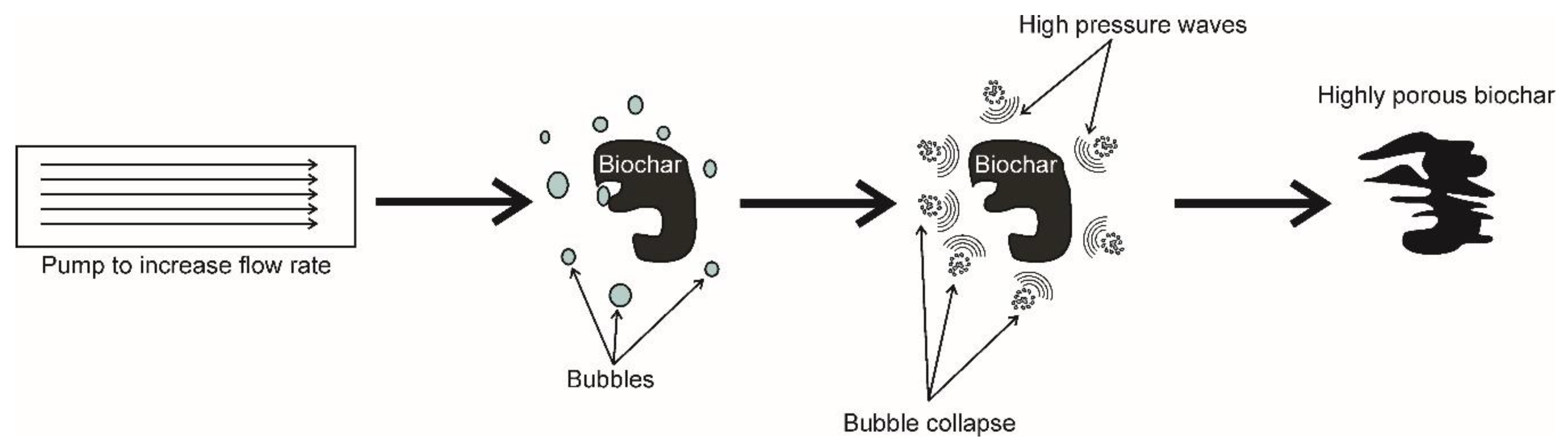
  139. Albanese, L.; Baronti, S.; Liguori, F.; Meneguzzo, F.; Barbaro, P.; Vaccari, F.P. Hydrodynamic cavitation as an energy efficient process to increase biochar surface area and porosity: A case study. J. Clean. Prod. 2019, 210, 159–169. [Google Scholar] [CrossRef]
  140. Dong, H.; Zhang, C.; Hou, K.; Cheng, Y.; Deng, J.; Jiang, Z.; Tang, L.; Zeng, G. Removal of trichloroethylene by biochar supported nanoscale zero-valent iron in aqueous solution. Sep. Purif. Technol. 2017, 188, 188–196. [Google Scholar] [CrossRef]
  141. Lawrinenko, M.; Laird, D.A. Anion exchange capacity of biochar. Green Chem. 2015, 17, 4628–4636. [Google Scholar] [CrossRef] [Green Version]
  142. Mortazavian, S.; Jones-Lepp, T.; Bae, J.H.; Chun, D.; Bandala, E.R.; Moon, J. Heat-treated biochar impregnated with zero-valent iron nanoparticles for organic contaminants removal from aqueous phase: Material characterizations and kinetic studies. J. Ind. Eng. Chem. 2019, 76, 197–214. [Google Scholar] [CrossRef]
  143. Yang, F.; Zhang, S.; Sun, Y.; Cheng, K.; Li, J.; Tsang, D.C.W. Fabrication and characterization of hydrophilic corn stalk biochar-supported nanoscale zero-valent iron composites for efficient metal removal. Bioresour. Technol. 2018, 265, 490–497. [Google Scholar] [CrossRef]
  144. Lyu, H.; Gao, B.; He, F.; Zimmerman, A.R.; Ding, C.; Huang, H.; Tang, J. Effects of ball milling on the physicochemical and sorptive properties of biochar: Experimental observations and governing mechanisms. Environ. Pollut. 2018, 233, 54–63. [Google Scholar] [CrossRef]
  145. Tu, Y.; Peng, Z.; Xu, P.; Lin, H.; Wu, X.; Yang, L.; Huang, J. Characterization and Application of Magnetic Biochars from Corn Stalk by Pyrolysis and Hydrothermal Treatment. BioResources 2017, 12, 1077–1089. [Google Scholar] [CrossRef] [Green Version]
  146. Frolova, L.; Kharytonov, M. Synthesis of Magnetic Biochar for Efficient Removal of Cr(III) Cations from the Aqueous Medium. Adv. Mater. Sci. Eng. 2019, 2019, 1–7. [Google Scholar] [CrossRef] [Green Version]
  147. Mahdavi, M.; Ahmad, M.B.; Haron, M.J.; Namvar, F.; Nadi, B.; Ab Rahman, M.Z.; Amin, J. Synthesis, surface modification and characterisation of biocompatible magnetic iron oxide nanoparticles for biomedical applications. Molecules 2013, 18, 7533–7548. [Google Scholar] [CrossRef] [Green Version]
  148. Mascolo, M.C.; Pei, Y.; Ring, T.A. Room Temperature Co-Precipitation Synthesis of Magnetite Nanoparticles in a Large ph Window with Different Bases. Materials 2013, 6, 5549–5567. [Google Scholar] [CrossRef] [PubMed] [Green Version]
  149. da Guarda Souza, M.O.; dos Santos, M.V.R.; Castro, L.M.F.; da Silva, C.P. Production and in situ transformation of hematite into magnetite from the thermal decomposition of iron nitrate or goethite mixed with biomass. J. Therm. Anal. Calorim. 2020, 139, 1731–1739. [Google Scholar] [CrossRef]
  150. Rashid, H.; Mansoor, M.A.; Haider, B.; Nasir, R.; Abd Hamid, S.B.; Abdulrahman, A. Synthesis and characterization of magnetite nano particles with high selectivity using in-situ precipitation method. Sep. Sci. Technol. 2020, 55, 1207–1215. [Google Scholar] [CrossRef] [Green Version]
  151. Giorcelli, M.; Savi, P.; Yasir, M.; Miscuglio, M.; Yahya, M.H.; Tagliaferro, A. Investigation of epoxy resin/multiwalled carbon nanotube nanocomposite behavior at low frequency. J. Mater. Res. 2014, 30, 101–107. [Google Scholar] [CrossRef]
  152. Giorcelli, M.; Khan, A.; Pugno, N.M.; Rosso, C.; Tagliaferro, A. Biochar as a cheap and environmental friendly filler able to improve polymer mechanical properties. Biomass Bioenergy 2019, 120, 219–223. [Google Scholar] [CrossRef] [Green Version]
  153. Zhang, Q.; Cai, H.; Ren, X.; Kong, L.; Liu, J.; Jiang, X. The dynamic mechanical analysis of highly filled rice husk biochar/High-density polyethylene composites. Polymers 2017, 9, 628. [Google Scholar] [CrossRef] [PubMed] [Green Version]
  154. Zhang, Q.; Cai, H.; Yang, K.; Yi, W. Effect of biochar on mechanical and flame retardant properties of wood—Plastic composites. Results Phys. 2017, 7, 2391–2395. [Google Scholar] [CrossRef]
  155. Barrett, J.R. Compost: Your Trash, Nature’s Treasure! ChemMatters. 2017. Available online: https://www.acs.org/content/acs/en/education/resources/highschool/chemmatters/past-issues/2017-2018/october2017/composting-your-trash-natures-treasure.html (accessed on 21 March 2021).
  156. Prost, K.; Borchard, N.; Siemens, J.; Kautz, T.; Séquaris, J.-M.; Möller, A.; Amelung, W. Biochar Affected by Composting with Farmyard Manure. J. Environ. Qual. 2013, 42, 164–172. [Google Scholar] [CrossRef] [Green Version]
  157. Godlewska, P.; Schmidt, H.P.; Ok, Y.S.; Oleszczuk, P. Biochar for composting improvement and contaminants reduction. A review. Bioresour. Technol. 2017, 246, 193–202. [Google Scholar] [CrossRef]
  158. Agegnehu, G.; Srivastava, A.K.; Bird, M.I. The role of biochar and biochar-compost in improving soil quality and crop performance: A review. Appl. Soil Ecol. 2017, 119, 156–170. [Google Scholar] [CrossRef]
  159. Czekała, W.; Jezowska, A.; Chełkowski, D. The use of biochar for the production of organic fertilizers. J. Ecol. Eng. 2019, 20, 1–8. [Google Scholar] [CrossRef]
  160. Zhu, D.; Pignatello, J.J. Characterization of aromatic compound sorptive interactions with black carbon (charcoal) assisted by graphite as a model. Environ. Sci. Technol. 2005, 39, 2033–2041. [Google Scholar] [CrossRef] [PubMed]
  161. Lattao, C.; Cao, X.; Mao, J.; Schmidt-Rohr, K.; Pignatello, J.J. Influence of molecular structure and adsorbent properties on sorption of organic compounds to a temperature series of wood chars. Environ. Sci. Technol. 2014, 48, 4790–4798. [Google Scholar] [CrossRef] [PubMed]
  162. Xiao, F.; Pignatello, J.J. Interactions of triazine herbicides with biochar: Steric and electronic effects. Water Res. 2015, 80, 179–188. [Google Scholar] [CrossRef] [PubMed] [Green Version]
  163. Conte, P.; Lo Meo, P. Nuclear Magnetic Resonance with Fast Field-Cycling Setup: A Valid Tool for Soil Quality Investigation. Agronomy 2020, 10, 1040. [Google Scholar] [CrossRef]
  164. Conte, P. Environmental Applications of Fast Field-cycling NMR Relaxometry. In Field-cycling NMR Relaxometry: Instrumentation, Model Theories and Applications; Kimmich, R., Ed.; The Royal Society of Chemistry: Croydon, UK, 2019; pp. 229–254. ISBN 9781788011549. [Google Scholar]
  165. Laidler, K.J.; Glasstone, S. Rate, order and molecularity in chemical kinetics. J. Chem. Educ. 1948, 25, 383–387. [Google Scholar] [CrossRef]
  166. Tong, Y.; McNamara, P.J.; Mayer, B.K. Adsorption of organic micropollutants onto biochar: A review of relevant kinetics, mechanisms and equilibrium. Environ. Sci. Water Res. Technol. 2019, 5, 821–838. [Google Scholar] [CrossRef]
  167. Yang, X.; Al-Duri, B. Kinetic modeling of liquid-phase adsorption of reactive dyes on activated carbon. J. Colloid Interface Sci. 2005, 287, 25–34. [Google Scholar] [CrossRef] [PubMed]
  168. Kołodyńska, D.; Wnetrzak, R.; Leahy, J.J.; Hayes, M.H.B.; Kwapiński, W.; Hubicki, Z. Kinetic and adsorptive characterization of biochar in metal ions removal. Chem. Eng. J. 2012, 197, 295–305. [Google Scholar] [CrossRef]
  169. Baghdadi, M. UT (University of Tehran) isotherm as a novel and useful adsorption isotherm for investigation of adsorptive removal of pollutants. J. Environ. Chem. Eng. 2017, 5, 1906–1919. [Google Scholar] [CrossRef]
  170. Guarín, J.R.; Moreno-Pirajan, J.C.; Giraldo, L. Kinetic Study of the Bioadsorption of Methylene Blue on the Surface of the Biomass Obtained from the Algae D. antarctica. J. Chem. 2018, 2018, 2124845. [Google Scholar] [CrossRef] [Green Version]
  171. Li, Q.; Tang, L.; Hu, J.; Jiang, M.; Shi, X.; Zhang, T.; Li, Y.; Pan, X. Removal of toxic metals from aqueous solution by biochars derived from long-root Eichhornia crassipes. R. Soc. Open Sci. 2018, 5, 180966. [Google Scholar] [CrossRef] [PubMed] [Green Version]
  172. Taşar, Ş.; Özer, A. A thermodynamic and kinetic evaluation of the adsorption of pb(Ii) ions using peanut (arachis hypogaea) shell-based biochar from aqueous media. Polish J. Environ. Stud. 2020, 29, 293–305. [Google Scholar] [CrossRef]
  173. Ganguly, P.; Sarkhel, R.; Das, P. Synthesis of pyrolyzed biochar and its application for dye removal: Batch, kinetic and isotherm with linear and non-linear mathematical analysis. Surf. Interfaces 2020, 20, 100616. [Google Scholar] [CrossRef]
  174. Harikishore Kumar Reddy, D.; Lee, S.M. Magnetic biochar composite: Facile synthesis, characterization, and application for heavy metal removal. Colloids Surfaces A Physicochem. Eng. Asp. 2014, 454, 96–103. [Google Scholar] [CrossRef]
  175. Zhou, Y.; Liu, X.; Xiang, Y.; Wang, P.; Zhang, J.; Zhang, F.; Wei, J.; Luo, L.; Lei, M.; Tang, L. Modification of biochar derived from sawdust and its application in removal of tetracycline and copper from aqueous solution: Adsorption mechanism and modelling. Bioresour. Technol. 2017, 245, 266–273. [Google Scholar] [CrossRef]
  176. Reguyal, F.; Sarmah, A.K.; Gao, W. Synthesis of magnetic biochar from pine sawdust via oxidative hydrolysis of FeCl2 for the removal sulfamethoxazole from aqueous solution. J. Hazard. Mater. 2017, 321, 868–878. [Google Scholar] [CrossRef]
  177. Kim, K.H.; Szulejko, J.E.; Raza, N.; Kumar, V.; Vikrant, K.; Tsang, D.C.W.; Bolan, N.S.; Ok, Y.S.; Khan, A. Identifying the best materials for the removal of airborne toluene based on performance metrics—A critical review. J. Clean. Prod. 2019, 241, 118408. [Google Scholar] [CrossRef]
  178. Vikrant, K.; Kim, K.H. Nanomaterials for the adsorptive treatment of Hg(II) ions from water. Chem. Eng. J. 2019, 358, 264–282. [Google Scholar] [CrossRef]
  179. Vikrant, K.; Kim, K.H.; Szulejko, J.E. The retrograde adsorption phenomenon at the onset of breakthrough and its quantitation: An experimental case study for gaseous toluene on activated carbon surface. Environ. Res. 2019, 178, 108737. [Google Scholar] [CrossRef] [PubMed]
  180. Younis, S.A.; Motawea, E.A.; Moustafa, Y.M.; Lee, J.; Kim, K.H. A strategy for the efficient removal of chlorophenols in petrochemical wastewater by organophilic and aminated silica@alginate microbeads: Taguchi optimization and isotherm modeling based on partition coefficient. J. Hazard. Mater. 2020, 397, 122792. [Google Scholar] [CrossRef] [PubMed]
  181. Zahedifar, M.; Moosavi, A.A. Modeling desorption kinetics of the native and applied zinc in biochar-amended calcareous soils of different land uses. Environ. Earth Sci. 2017, 76, 567. [Google Scholar] [CrossRef]
  182. Tian, H.; Hu, Q.; Wang, J.; Chen, D.; Yang, Y.; Bridgwater, A.V. Kinetics Study on the CO2 Gasification of Biochar Derived from Miscanthus at Different Processing Conditions. Energy 2021, 217, 119341. [Google Scholar] [CrossRef]
  183. Langmuir, I. The constitution and fundamental properties of solids and liquids. Part I. Solids. J. Am. Chem. Soc. 1916, 38, 2221–2295. [Google Scholar] [CrossRef] [Green Version]
  184. Langmuir, I. The Constitution and Fundamental Properties of Solids and Liquids. II. Liquids. J. Am. Chem. Soc. 1917, 39, 1848–1906. [Google Scholar] [CrossRef] [Green Version]
  185. Langmuir, I. The Adsorption of Gases on Plane Surfaces of Mica. J. Am. Chem. Soc. 1918, 40, 1361–1403. [Google Scholar] [CrossRef] [Green Version]
  186. Sohn, S.; Kim, D. Modification of Langmuir isotherm in solution systems—Definition and utilization of concentration dependent factor. Chemosphere 2005, 58, 115–123. [Google Scholar] [CrossRef]
  187. Belhachemi, M.; Addoun, F. Comparative adsorption isotherms and modeling of methylene blue onto activated carbons. Appl. Water Sci. 2011, 1, 111–117. [Google Scholar] [CrossRef] [Green Version]
  188. Tzabar, N.; ter Brake, H.J.M. Adsorption isotherms and Sips models of nitrogen, methane, ethane, and propane on commercial activated carbons and polyvinylidene chloride. Adsorption 2016, 22, 901–914. [Google Scholar] [CrossRef] [Green Version]
  189. Ahmed, M.B.; Zhou, J.L.; Ngo, H.H.; Guo, W.; Johir, M.A.H.; Sornalingam, K. Single and competitive sorption properties and mechanism of functionalized biochar for removing sulfonamide antibiotics from water. Chem. Eng. J. 2017, 311, 348–358. [Google Scholar] [CrossRef]
  190. Liu, Y. Some consideration on the Langmuir isotherm equation. Colloids Surf. A Physicochem. Eng. Asp. 2006, 274, 34–36. [Google Scholar] [CrossRef]
  191. Kimmich, R.; Anoardo, E. Field-cycling NMR relaxometry. Prog. Nucl. Magn. Reson. Spectrosc. 2004, 44, 257–320. [Google Scholar] [CrossRef]
  192. Conte, P.; Alonzo, G. Environmental NMR: Fast-field-cycling relaxometry. eMagRes 2013, 2, 389–398. [Google Scholar] [CrossRef] [Green Version]
  193. Steele, R.M.; Korb, J.P.; Ferrante, G.; Bubici, S. New applications and perspectives of fast field cycling NMR relaxometry. Magn. Reson. Chem. 2016, 54, 502–509. [Google Scholar] [CrossRef]
  194. Conte, P.; Schmidt, H.-P. Soil-water interactions unveiled by fast field cycling NMR relaxometry. eMagRes 2017, 6, 453–464. [Google Scholar] [CrossRef]
  195. Bubici, S.; Korb, J.-P.; Kučerik, J.; Conte, P. Evaluation of the surface affinity of water in three biochars using fast field cycling NMR relaxometry. Magn. Reson. Chem. 2016, 54, 365–370. [Google Scholar] [CrossRef] [PubMed] [Green Version]
  196. Lo Meo, P.; Mundo, F.; Terranova, S.; Conte, P.; Chillura Martino, D. Water Dynamics at the Solid-Liquid Interface to Unveil the Textural Features of Synthetic Nanosponges. J. Phys. Chem. B 2020, 124, 1847–1857. [Google Scholar] [CrossRef]
  197. Kalra, K.; Gorle, S.; Cavallo, L.; Oliva, R.; Chawla, M. Occurrence and stability of lone pair-π and OH-π interactions between water and nucleobases in functional RNAs. Nucleic Acids Res. 2020, 48, 5825–5838. [Google Scholar] [CrossRef] [PubMed]
  198. Jain, A.; Ramanathan, V.; Sankararamakrishnan, R. Lone pair ⋯ π interactions between water oxygens and aromatic residues: Quantum chemical studies based on high-resolution protein structures and model compounds. Protein Sci. 2009, 18, 595–605. [Google Scholar] [CrossRef] [Green Version]
  199. Conte, P. Effects of ions on water structure: A low-field 1H T1 NMR relaxometry approach. Magn. Reson. Chem. 2015, 53, 711–718. [Google Scholar] [CrossRef] [Green Version]
  200. Conte, P.; Laudicina, V.A. Mechanisms of organic coating on the surface of a poplar biochar. Curr. Org. Chem. 2017, 21, 559–565. [Google Scholar] [CrossRef] [Green Version]
  201. Conte, P.; Nestle, N. Water dynamics in different biochar fractions. Magn. Reson. Chem. 2015, 53, 726–734. [Google Scholar] [CrossRef] [Green Version]
  202. Lentz, R.D.; Ippolito, J.A.; Lehrsch, G.A. Biochar, Manure, and Sawdust Alter Long-Term Water Retention Dynamics in Degraded Soil. Soil Sci. Soc. Am. J. 2019, 83, 1491–1501. [Google Scholar] [CrossRef]
  203. Hussain, R.; Ravi, K.; Garg, A. Influence of biochar on the soil water retention characteristics (SWRC): Potential application in geotechnical engineering structures. Soil Tillage Res. 2020, 204, 104713. [Google Scholar] [CrossRef]
  204. Yi, S.; Chang, N.Y.; Imhoff, P.T. Predicting water retention of biochar-amended soil from independent measurements of biochar and soil properties. Adv. Water Resour. 2020, 14, 103638. [Google Scholar] [CrossRef]
  205. Juriga, M.; Šimanský, V. Effect of biochar on soil structure—Review. Acta Fytotech. Zootech. 2018, 21, 11–19. [Google Scholar] [CrossRef]
  206. Rillig, M.C.; Wagner, M.; Salem, M.; Antunes, P.M.; George, C.; Ramke, H.G.; Titirici, M.M.; Antonietti, M. Material derived from hydrothermal carbonization: Effects on plant growth and arbuscular mycorrhiza. Appl. Soil Ecol. 2010, 45, 238–242. [Google Scholar] [CrossRef]
  207. Jaiswal, A.K.; Alkan, N.; Elad, Y.; Sela, N.; Philosoph, A.M.; Graber, E.R.; Frenkel, O. Molecular insights into biochar-mediated plant growth promotion and systemic resistance in tomato against Fusarium crown and root rot disease. Sci. Rep. 2020, 10, 13934. [Google Scholar] [CrossRef] [PubMed]
  208. Nielsen, S.; Joseph, S.; Ye, J.; Chia, C.; Munroe, P.; van Zwieten, L.; Thomas, T. Crop-season and residual effects of sequentially applied mineral enhanced biochar and N fertiliser on crop yield, soil chemistry and microbial communities. Agric. Ecosyst. Environ. 2018, 255, 52–61. [Google Scholar] [CrossRef]
  209. Blackwell, P.; Joseph, S.; Munroe, P.; Anawar, H.M.; Storer, P.; Gilkes, R.J.; Solaiman, Z.M. Influences of Biochar and Biochar-Mineral Complex on Mycorrhizal Colonisation and Nutrition of Wheat and Sorghum. Pedosphere 2015, 25, 686–695. [Google Scholar] [CrossRef]
  210. Das, S.K.; Ghosh, G.K.; Avasthe, R. Valorizing biomass to engineered biochar and its impact on soil, plant, water, and microbial dynamics: A review. Biomass Convers. Biorefinery 2020. [Google Scholar] [CrossRef]
  211. Paz-Ferreiro, J.; Lu, H.; Fu, S.; Méndez, A.; Gascó, G. Use of phytoremediation and biochar to remediate heavy metal polluted soils: A review. Solid Earth 2014, 5, 65–75. [Google Scholar] [CrossRef] [Green Version]
  212. Hao, N.; Cao, J.; Ye, J.; Zhang, C.; Li, C.; Bate, B. Content and morphology of lead remediated by activated carbon and biochar: A spectral induced polarization study. J. Hazard. Mater. 2021, 411, 124605. [Google Scholar] [CrossRef]
  213. Conte, P.; Zena, A.; Pilidis, G.; Piccolo, A. Increased retention of polycyclic aromatic hydrocarbons in soils induced by soil treatment with humic substances. Environ. Pollut. 2001, 112, 27–31. [Google Scholar] [CrossRef]
  214. Zhou, J.; Liu, Y.; Han, Y.; Jing, F.; Chen, J. Bone-derived biochar and magnetic biochar for effective removal of fluoride in groundwater: Effects of synthesis method and coexisting chromium. Water Environ. Res. 2019, 91, 588–597. [Google Scholar] [CrossRef]
  215. Liu, W.J.; Jiang, H.; Yu, H.Q. Development of Biochar-Based Functional Materials: Toward a Sustainable Platform Carbon Material. Chem. Rev. 2015, 115, 12251–12285. [Google Scholar] [CrossRef] [PubMed]
  216. Evans, M.R.; Jackson, B.E.; Popp, M.; Sadaka, S. Chemical properties of biochar materials manufactured from agricultural products common to the southeast united states. Horttechnology 2017, 27, 16–23. [Google Scholar] [CrossRef] [Green Version]
  217. Sun, H.; Hockaday, W.C.; Masiello, C.A.; Zygourakis, K. Multiple controls on the chemical and physical structure of biochars. Ind. Eng. Chem. Res. 2012, 51, 1587–1597. [Google Scholar] [CrossRef]
  218. Zhang, S.; Zhu, X.; Zhou, S.; Shang, H.; Luo, J.; Tsang, D.C.W. Hydrothermal Carbonization for Hydrochar Production and Its Application. In Biochar from Biomass and Waste—Fundamentals and Applications; Sik Ok, Y., Tsang, D.C.W., Bolan, N., Novak, J.M., Eds.; Elsevier: Amsterdam, The Netherlands, 2019; pp. 275–294. ISBN 9780128117293. [Google Scholar]
  219. Wiedner, K.; Naisse, C.; Rumpel, C.; Pozzi, A.; Wieczorek, P.; Glaser, B. Chemical modification of biomass residues during hydrothermal carbonization—What makes the difference, temperature or feedstock? Org. Geochem. 2013, 54, 91–100. [Google Scholar] [CrossRef]
  220. NETL. Detailed Gasification Chemistry. Available online: https://www.netl.doe.gov/research/coal/energy-systems/gasification/gasifipedia/gasification-chemistry (accessed on 2 February 2021).
Figure 1. Graph showing the increasing number of papers published in the last two decades. The source of the figures are “Web of Science”, where only the term, “biochar”, was used as a keyword.
Agronomy 11 00615 g001
Figure 2. Simplified carbon dioxide cycle. (A) CO2 is photosynthetically converted in carbonaceous plant metabolites. Once the plant dies, the organic material returns back to CO2. (B) If the organic matter from dead plants is pyrolyzed and then the produced carbonaceous material is applied to soils, the rate of its conversion to CO2 is reduced, thereby allowing carbon sequestration in soils, reducing the amount of atmospheric carbon dioxide.
Agronomy 11 00615 g002
Figure 3. Example of biochar structure intended as a stacked crystalline graphene sheets and randomly ordered amorphous aromatic structures (this figure has been reproduced from Reference [51]).
Agronomy 11 00615 g003
Figure 4. Photo acquired by a scanning electron microscope (SEM) of a biochar from fir biomass charred at 500 °C for a period of 30 min via the lab–muffle–furnace method (Appendix A). The honeycomb-like group of pores, due to the cellular structure of the feedstock, are clearly visible (unpublished results from the group of P.C.).
Agronomy 11 00615 g004
Figure 5. H-bond rupture mechanism by ionic liquids. IL stands for ionic liquid, C+ is the cation moiety, while A− is the anion one [79].
Agronomy 11 00615 g005
Figure 6. Schematic representation of the chemical transformations occurring in biomasses as pyrolysis temperature increases.
Agronomy 11 00615 g006
Figure 7. Schematic representation of pore formation during pyrolysis. The leftmost side of the figure shows the honeycomb-like cells of the biomass prior of the thermal degradation. As the temperature increases pores are formed (central part of the figure). Pore coalescence due to the release of volatile organic components and salt melting provokes hole enlargement and reduction of the biochar surface area.
Agronomy 11 00615 g007
Figure 8. Chemical pathways involved in the changes of biomass surface chemistry during the pyrolysis in CO2/NH3 atmosphere. All the reactions described here do not account for the stoichiometry. The scheme has been re-elaborated from references [125,126].
Agronomy 11 00615 g008
Figure 9. Scheme of pore formation in CO2, NH3, and CO2/NH3 atmospheres. The grey color indicates the formation of a “glue”-like layer made by N-containing groups. The scheme has been elaborated from References [125,126].
Agronomy 11 00615 g009
Figure 10. Oxygen-enriched biochar produced by the application of an air steam in mild temperature conditions.
Agronomy 11 00615 g010
Figure 11. Scheme of the hydrodynamic cavitation method with a pump directing the water flow towards the biochar.
Agronomy 11 00615 g011
Figure 12. Simulation curves for the pseudo−first order (A), pseudo−second order (B), and pseudo−third order (C) absorption kinetics on biochar. The simulations have been performed by using Origin Pro 7.5.
Agronomy 11 00615 g012
Figure 13. (A) Langmuir isotherms obtained by simulation of Equation (32). The different curves have been acquired by using the value of the equilibrium constant reported in the graph. (B). Langmuir isotherms obtained by simulation of Equation (33). The different curves were obtained by fixing the k e value to 0.1 and by using the X values reported in graph.
Agronomy 11 00615 g013
Figure 14. Different possible bindings between water molecules and biochar. Water can interact with biochar’s surface by OH–π bonding, Van der Waals interactions, and coordination linkages. The latter occur when the electron-rich oxygen in water lays in the proximity of a metal ion (dark grey outgrowths). The blue spheres represent a solvated cation (e.g., ammonium).
Agronomy 11 00615 g014
Figure 15. Example of degradation of a pollutant (bisphenol A) on the surface of a persulfate activated biochar. The reaction scheme has been re-elaborated with permission from Reference [138].
Agronomy 11 00615 g015
Table 1. Types of biomasses to be used for the production of biochar according to the European Biochar Certificate [48].
OriginFeedstock
Local waste collection services with waste separationBiodegradable waste, biodegradable waste with kitchen waste, biodegradable waste with kitchen waste and leftovers
Garden wastesLeaves, flowers, vegetables, roots, pruning from trees, vines and bushes, clippings from nature conservation measures, hay, grass
Agriculture and forestryHarvest leftovers, straw, used straw, husks and grain dust, grain, feedstuffs, pruning from biomass plantations grown for energy or biomass uses (renewable resources), pruning from trees, vines and bushes, seeds and plants, bark, chipping, wood, sawdust, wood shaving, wood wool
Kitchens and canteensKitchen, canteen, restaurant leftovers
Vegetable productionsMaterial from washing, cleaning, peeling, centrifuging and separation
Waterway maintenance (vegetable material)Raked material, flotsam, fishing residues, harvested material, water plants
Materials from food and packagingSeasoning residues; residues from potatoes, corn, rice and starch production; residues from dairy processing; fruit and grain residues; marc; residues from beer production
TextilesCellulose, cotton, vegetable fibers, hemp, wool leftovers and wool dust
PaperPaper fiber sludge
Biogas plantsFermentation residues
Table 2. Technical parameters for biochars established by the European Biochar Certificate. The list is incomplete. It is, however, available in the link reported in Reference [48].
ParameterValue
H/C<0.7
O/C<0.4
Heavy metal contentPb < 150 g Mg−1; Cd < 1.5 g Mg−1; Cu < 100 g Mg−1; Ni < 50 g Mg−1; Hg < 1 g Mg−1; Zn < 400 g Mg−1; Cr < 90 g Mg−1
pH, bulk density, water, and ash contentThese are not fixed values. They must be measured and indicated
Polycyclic aromatic
hydrocarbons (PAH)
PAH content (sum of the EPA’s 16 priority pollutants) must be <6 mg kg−1 (<4 mg kg−1 for organic agriculture)
Polychlorinatedbiphenyls (PCB)<0.2 mg kg−1
Table 3. Different pyrolysis modes. They differ from each other for the heating rate, holding time, and the number of different products obtained.
Pyrolysis ModeHeating RateHolding TimeTypical Holding TemperatureBio-Oil (%, w w−1)Biochar (%, w w−1)Gas (%, w w−1)
FastVery high<2 s<550 °C70–8010–1510–15
ConventionalLow5 min up to few hours<600 °C40–5020–3030–40
SlowVery lowDays ≈400 °C303535
Publisher’s Note: MDPI stays neutral with regard to jurisdictional claims in published maps and institutional affiliations.

