Review

Polymeric Slippery Coatings: Nature and Applications

1
Department of Mechanical and Aerospace Engineering, Princeton University, Princeton, NJ 08544-5263, USA
2
Department of Mechanical and Nuclear Engineering, Virginia Commonwealth University, Richmond, VA 23284-3015, USA
*
Author to whom correspondence should be addressed.
Polymers 2014, 6(5), 1266-1311; https://doi.org/10.3390/polym6051266
Submission received: 18 February 2014 / Revised: 16 April 2014 / Accepted: 23 April 2014 / Published: 30 April 2014
(This article belongs to the Special Issue Biomimetic Polymers)

Abstract

:
We review recent developments in nature-inspired superhydrophobic and omniphobic surfaces. Water droplets beading on a surface at significantly high static contact angles and low contact-angle hystereses characterize superhydrophobicity. Microscopically, rough hydrophobic surfaces could entrap air in their pores resulting in a portion of a submerged surface with air–water interface, which is responsible for the slip effect. Suberhydrophobicity enhances the mobility of droplets on lotus leaves for self-cleaning purposes, so-called lotus effect. Amongst other applications, superhydrophobicity could be used to design slippery surfaces with minimal skin-friction drag for energy conservation. Another kind of slippery coatings is the recently invented slippery liquid-infused porous surfaces (SLIPS), which are one type of omniphobic surfaces. Certain plants such as the carnivorous Nepenthes pitcher inspired SLIPS. Their interior surfaces have microstructural roughness, which can lock in place an infused lubricating liquid. The lubricant is then utilized as a repellent surface for other liquids such as water, blood, crude oil, and alcohol. In this review, we discuss the concepts of both lotus effect and Nepenthes slippery mechanism. We then present a review of recent advances in manufacturing polymeric and non-polymeric slippery surfaces with ordered and disordered micro/nanostructures. Furthermore, we discuss the performance and longevity of such surfaces. Techniques used to characterize the surfaces are also detailed. We conclude the article with an overview of the latest advances in characterizing and using slippery surfaces for different applications.

Graphical Abstract

1. Introduction

Bioinspired slippery surfaces received significant attention in the last two decades. Superhydrophobic surfaces (i.e., water-repellent surfaces) have been developed by well designed chemistry and roughness [1,2,3,4,5,6,7,8,9,10,11,12,13]. Superhydrophobicity could be achieved by a combination of low surface energy and micro- or nanoscale surface structure. The phenomenon is primarily manifested by water droplets beading on the solid surface with static contact angles exceeding 150° and significantly low contact-angle hystereses. Examples of such surfaces in nature are the self-cleaning lotus leaves [14] and water striders [15].
Several models were proposed to explain superhydrophobicity. According to Lafuma and Quéré [16], superhydrophobicity could be explained using the models independently developed by Wenzel [17] and Cassie [18]. The former is more applicable to slightly hydrophobic materials (contact angles just above 90 degrees for a smooth surface). Both models have a linear relation between the apparent contact angle on a rough surface and the corresponding contact angle on a smooth surface. The Wenzel and Cassie models intersect at a contact angle that Lafuma and Quéré called “critical angle”, below which the metastability of the Cassie state could be observed. Therefore, in order to avoid the metastability, the material of the surface should have a smooth-surface contact angle greater than the critical angle. Microscopically rough hydrophobic surfaces could entrap air in their pores resulting in a surface with both air–water and solid–water interfaces. The ratio of the area of the air–water interface to the total surface area is called gas void fraction. The presence of the air–water interface is responsible for the slip effect, characterized by an effective “slip length” [19]. This, in turn, results in a significant reduction in the skin-friction drag exerted on a moving, submerged surface [6,10,13]. As long as air pockets are entrapped in the surface pores, the surface remains superhydrophobic. Especially in underwater applications, the longevity of a superhydrophobic surface—how long the surface could maintain the entrapped air—is critical [8,9,11,20]. Recent overviews of the phenomenon are available [12,13,21]. The last reference in particular emphasizes the dominant role of surface tension forces at the small scale.
Oleophobic coatings provide a different kind of slippery surfaces that could resist wetting of water as well as other lower surface tension liquids such as hexadecane, dodecane, octane, and ethylene glycol [22,23,24,25,26,27,28,29,30]. Since such surfaces could repel different kind of liquids, they are considered omniphobic. Superoleophobicity could be achieved by a combination of three parameters: surface roughness, low surface energy, and local curvature of the surface microsrtucture (re-entrant geometry) [22]. The curvature could affect the apparent contact angle and hysteresis. The stability of the air–oil interface (plastron) under loads was experimentally demonstrated by Jin et al. [27]. They also showed that drag reduction could be achieved by such surfaces. The coatings could be utilized in a wide range of applications including resisting biofouling and self-cleaning in water polluted oil slicks.
Another example of manmade omniphobic coatings is called “slippery liquid-infused porous surfaces (SLIPS)” [31]. This coating was inspired by the Nepenthes pitcher plant. SLIPS was engineered to enhance the wetting properties of the surface for a low-surface-energy intermediary infused liquid (lubricant) such as DuPont Krytox oil in a fluorinated microstructural roughness. The oil is utilized as a repellent surface for different liquids such as water, blood, crude oil, alcohols, etc. This, in turn, could cause slip effect. Engineered SLIPS could be produced using microfabrications of ordered or disordered roughness. However, the well-matched surface energies of the lubricant and the solid surface is crucial [31]. The lubricant should not only wet the rough substrate but also be more attracted to the solid than the other liquid needed to be repelled. Additionally, both liquids must be immiscible. These surfaces could have an impact in applications requiring significantly low contact-angle hysteresis, self-healing, working under pressure, and anti-fouling.
This article provides a broad review of the most recent developments in nature-inspired hydrophobic and omniphobic surfaces. In the next section, we discuss both hydrophobic and omniphobic coatings in nature. In Section 3, we review different manufacturing techniques used for fabrication of different slippery surfaces. In Section 4, we discuss the latest techniques used to characterize skin-friction reduction, interface stability, and longevity of such surfaces. This will be followed in Section 5 by concluding remarks.

2. Slippery Surfaces in Nature

2.1. Hydrophobic Coatings
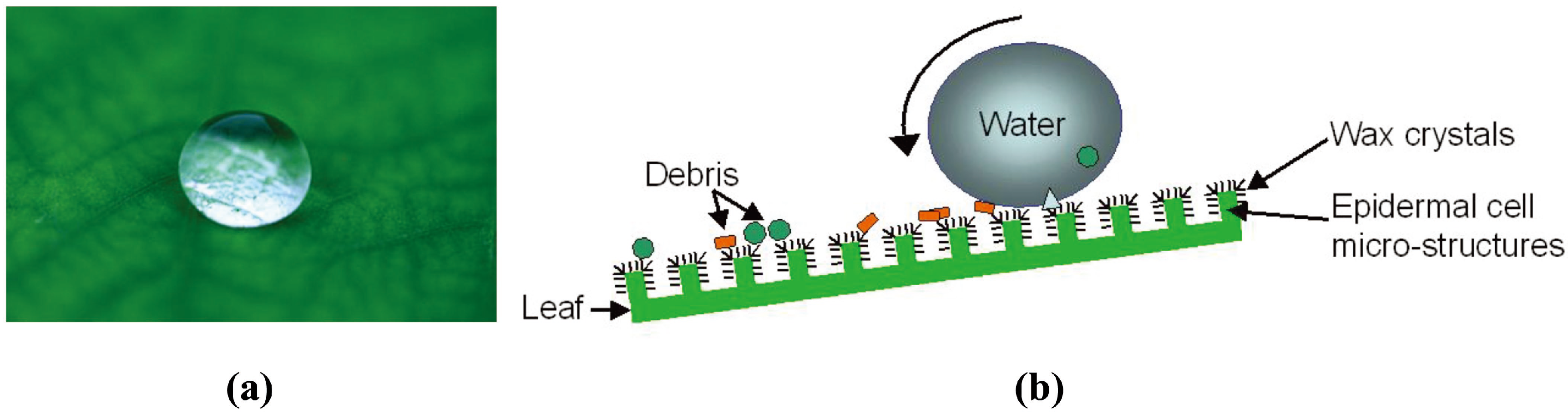
2.1.1. Lotus Leaves

The lotus leaves, Nelumbo nucifera, possess strong water repellent properties that enhance the mobility of rain drops, carrying dirt away, and creating a self-cleaning effect, so-called lotus effect. Neinhuis and Barthlott [14] obtained scanning electron microscope (SEM) images for several water-repellent plants and reported the micromorphological characteristics of 200 species. The authors demonstrated that the epidermal, outermost, cells of the lotus leaves form papillae, which act as microstructure roughness. The papillae are superimposed by a very dense layer of epicuticular waxes (wax crystals), also referred to as hair-like structures [32] or nanostructure roughness [33]. Figure 1 shows different degrees of magnification from zero to 106 of a lotus leaf using SEM images. Epicuticular waxes also have hydrophobic properties, which together with micro- and nanostructure roughness result in reduced contact area between water droplets and the leaf’s surface. This combination results in static contact angles on lotus leaves exceeding 150 degrees. If the surface is tilted, even with a slight angle, water droplets begin to roll off the leaves, and thus collect and remove dirt from the surface, which is a self-cleaning effect (Figure 2). Because of the micro- and nanostructure roughness, the contact area between dirt particles and the leaf’s surface is dramatically reduced. Thus, the adhesion between the particles and the surface can be lower than that between the particles and the droplets, facilitating particle removal. Accordingly, the lotus leaf is a symbol of purity in certain Asian religions [14].
Figure 1. Lotus leaf. (a) Zero magnification; from websites [34,35]. (b) Three different magnification of scanning electron microscope (SEM) images showing morphological micro- and nanostructures; from Koch et al. [33].
Polymers 06 01266 g001
Figure 2. (a) Water droplet beading on lotus leaf with static contact angle higher than 150 degrees; from website [36]. (b) Schematic illustration of lotus effect; from website [37].
Polymers 06 01266 g002
To demonstrate the importance of nanoscale wax crystals for the lotus effect, Cheng et al. [32] altered the surface structure of a lotus leaf without affecting the chemical composition. They heated the leaf to 150 °C to melt the waxy crystals, leaving the microstructures intact. The static contact angle of the thermally annealed leaf was found to decrease. On the other hand, Cheng and Rodak [38] investigated the effect of water condensation on the degree of hydrophobicity of the leaves. They demonstrated that lotus leaves could exhibit superhydrophobicity if water drops with macroscopic sizes were placed on their surfaces. However, hydrophilic behavior occurred when water was condensed on the surface from the vapor phase. During the condensation treatment, very small water drops were trapped within the nanohairy structures of lotus leaves. The drops were then growing or becoming connected to larger drops exhibiting hydrophilicity.
Neinhuis and Barthlott [14] reported that the lotus effect tends to keep the leaves dry, which helps to protect the plant against pathogens such as fungi by denying these parasitic organisms the moisture that they require to germinate. Moreover, since CO2 diffuses 104 times faster in air than in water, the water repellent leaves allow CO2 to be more easily absorbed, ensuring an adequate supply of this gas for photosynthesis, even in habitats with high air humidity [14].
The superhydrophobic phenomenon not only provides beneficial effects to certain plants but also characterizes some features of certain animals, as discussed in the following two subsubsections.

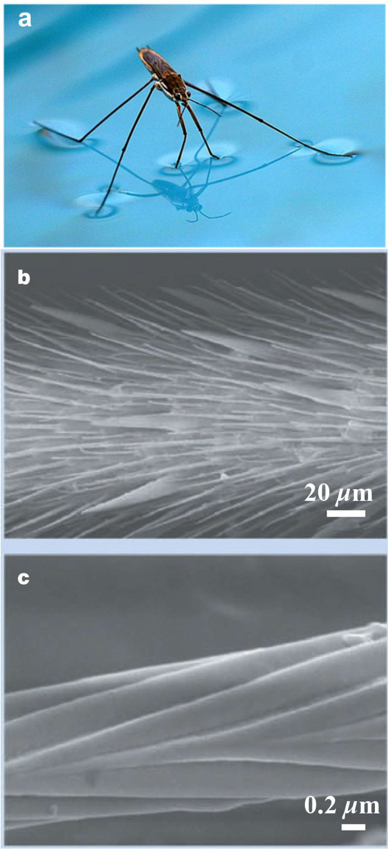
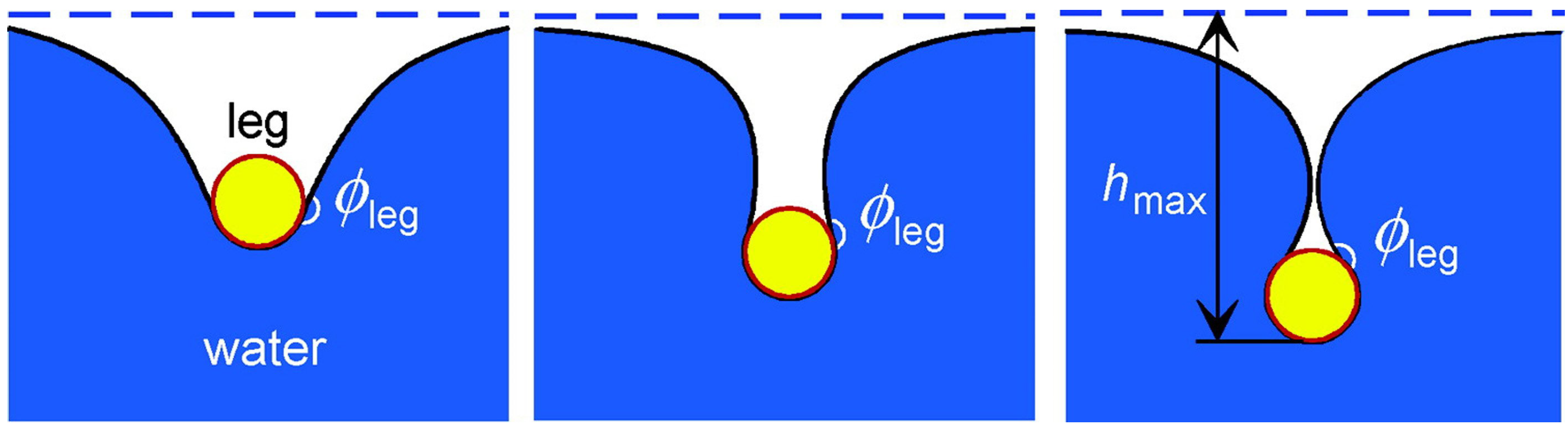
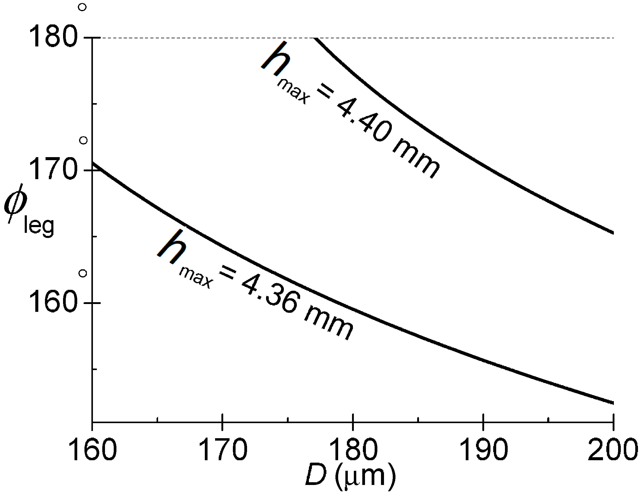
2.1.2. Water Striders

Water striders, Gerris remigis, or Jesus bugs, possess a very rare trait that allows them to walk on water. Water striders owe this ability to the hydrophobic waxy microhairs covering their legs, microsetae, which are superimposed with nanogrooves as shown in Figure 3.
Figure 3. (a) Water strider standing on water; from website [39]. (b) SEM image of water strider’s leg showing hydrophobic microsetae. (c) Higher magnification of single hair showing nanogrooves. (b,c) from Gao and Jiang [15].
Polymers 06 01266 g003
Air is entrapped between the micro- and nanostructured hairs, making their legs water repellent. Gao and Jiang [15] used a very sensitive balance system to determine the required force for a single leg to be sunk. They demonstrated that the buoyancy force is 15 times the total body weight. Furthermore, the volume of the displaced water caused by immersing a single leg is 300 times that of the leg itself. Feng et al. [40] have demonstrated the ultra-hydrophobicity of a water strider’s leg by combining a theoretical analysis with measurements. They determined how deep the leg can reach before piercing the water surface, as shown in Figure 4. Feng et al., showed that the maximum depth hmax depends on the diameter D and the contact angle of the leg ϕleg. Their results are shown in Figure 5. It is clear that for the diameter range of 140–180 µm and for the measured maximum depth of hmax = 4.38 ± 0.02 mm, the contact angle should be at least 168°, i.e., highly water repellent. Such a high contact angle allows water striders to stand on water, even in the presence of rain or water currents.
Figure 4. Transects of the water surface for the leg contacting the water to different depths until the maximum depth hmax is reached before piercing the water surface; from Feng et al. [40].
Polymers 06 01266 g004
Figure 5. Contact angle of the leg and dimple depth. Dependence of contact angle on leg’s diameter in order to form maximal dimple with depth hmax = 4.38 ± 0.02 mm; from Feng et al. [40].
Polymers 06 01266 g005
Water striders have the ability to flit about quickly, where the propulsive forces on the insect are generated by a combination of form drag and curvature forces [41]. According to Hu et al. [42], water striders use their superhydrophobic legs to generate hemispherical vortices, which transfer sufficient momentum beneath the water surface to develop the hydrodynamic force necessary to propel the insect, similar to using oars to move a boat. Several water-walking machines are inspired by water striders and other insects [43]. Such devices are designed and constructed to precisely mimic the natural locomotion mechanisms of the insects.
Gerris remigis are the natural predators of spiders and other insects that fall onto the water surface. Jesus bugs use their front legs to sense the ripples generated by a falling prey [44] and grab onto it. The superhydrophobicity of a water strider’s legs is its survival mechanism, allowing it to float, run on water, and sense prey for feeding. It is worth mentioning that other species such as spiders are covered with hydrophobic hairs similar to those of water striders, but for a different purpose. The entrapped air (plastron) is utilized by spiders for underwater breathing. The mechanics of plastron respiration was explained by Flynn and Bush [45].

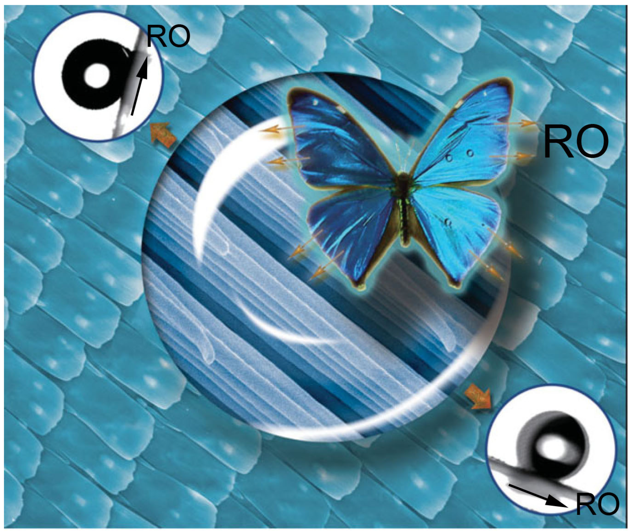
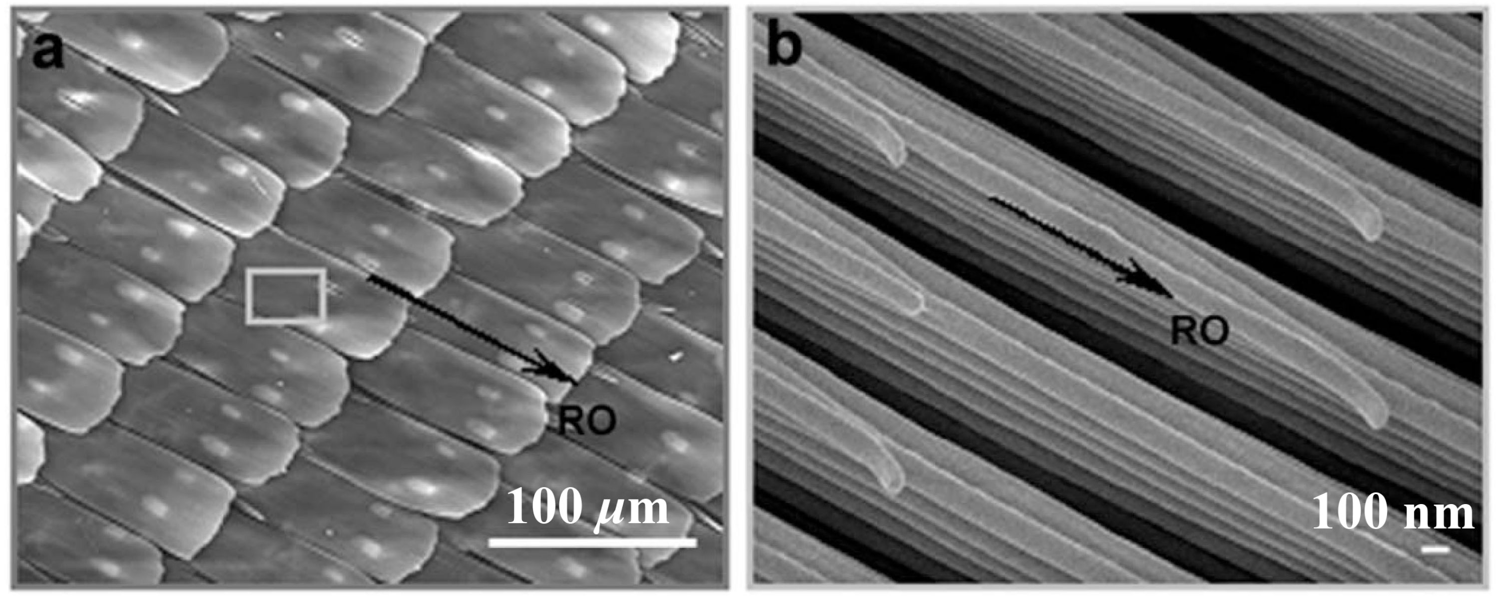
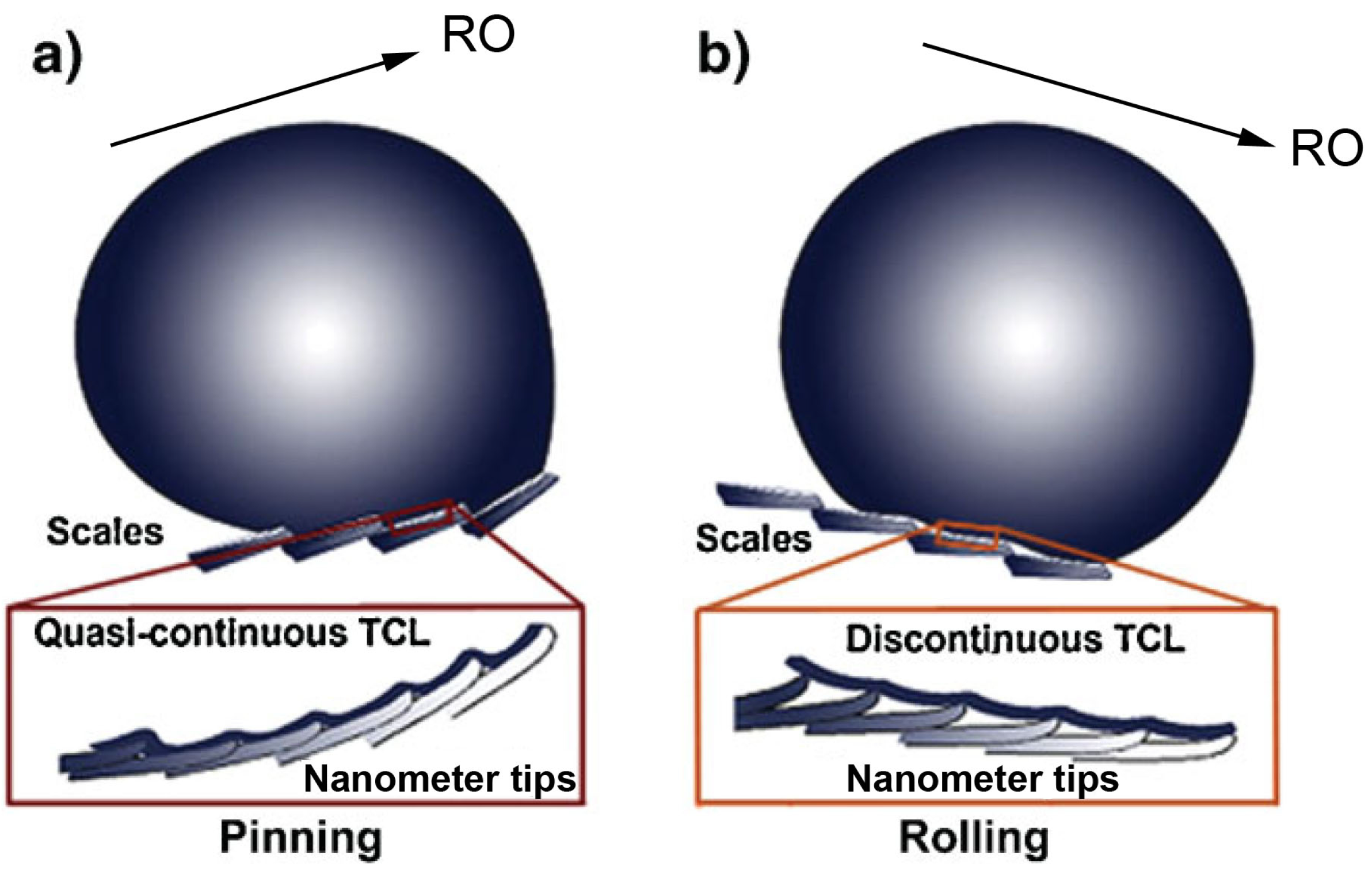
2.1.3. Butterfly Wings

Wings of the Morpho aega, a Neotropical butterfly found in Argentina, Brazil, and Paraguay have a natural mechanism that utilizes the superhydrophobic effect. The wings possess directional adhesive properties [46]. In a watery environment, droplets can easily roll off the wings’ surface along the radial outward (RO) direction from the central axis of the body exhibiting superhydrophobic state (Figure 6). However, droplets are tightly pinned against the surface in the opposite direction, demonstrating adhesive behavior in that direction.
Figure 6. Directional adhesion on superhydrophobic butterfly wings. Morpho aega with arrows indicating radial outward (RO) direction away from the central axis of the body. The droplet easily rolls of wing in the RO direction when wing is tilted downward by as low as 9° (bottom right). A water droplet is tightly pinned against wing’s surface when tilted upward up to 90° (top left). Adapted from Xia and Jiang [47].
Polymers 06 01266 g006
These favorable properties have a significant biological impact on the performance of the butterfly. First, they enhance the mobility of rain drops on the wings (in RO direction), carrying dirt away, and creating a self-cleaning effect similar to that of lotus leaves. Second, they provide adhesive effects in the other direction, and thus ensure the butterfly’s flight stability by avoiding the accumulation of dirt particles on the wing’s end near the body’s central axis [46].
Scanning electron microscope (SEM) observations by Zheng et al. [46] showed that the wings of the butterfly are covered by periodic arrangements of overlapping microquadrate scales forming hierarchy along the RO direction as shown in Figure 7a. Further magnified view is shown in Figure 7b, displaying that the microscales are superimposed with fine lamella-stacking nanostripes, which are stacked stepwise along the RO direction. The nanotips protrude on top of the stripes, which are tilted slightly upward.
Figure 7. (a) SEM image shows hierarchical microscales on the wing’s surface. (b) Further magnification shows that the microscales are superimposed with fine lamella-stacking nanostripes. From Zheng et al. [46].
Polymers 06 01266 g007
Zheng et al., proposed two modes to clarify the distinct adhesive properties of butterfly wings. When the wing was tilted upward, the flexible nanotips on the nanostrips and microscales took a close arrangement, which led to raising the nanotips together with the flexible microscales to closely contact the droplet (Figure 8a). Despite air being trapped in the nanogrooves, the complete “wet” contact of water with the nanotips and lamellae increased the contact area of the solid–water interface. This led to forming a quasi-continuous three-phase contact line (TCL) when the droplet attempted to move under the gravitational potential against the RO direction (bottom of Figure 8a). This arrangement results in pinning the droplet at many corners of the steps between the neighboring lamellae on top of the ridged nanostripes, leading to droplet adhesion on the wing as it is tilted upward, even when it is fully upright. This case is an intermediate state with the “wet” contact on top of ridging nanostripes and the “dry” contact on the air pockets trapped in nanogrooves.
When the wing was tilted downward, the microscales with nanostrips were separated from each other, and the nanotips tended to detach from the neighboring flexible strips and microscales as shown in Figure 8b. This led to producing nanoscale voids among the nanotips and the ridged nanostripes. In the voids, air is efficiently entrapped. Therefore, the droplet only touches the top of nanotips, with a minimal contact area of solid–water interface (“dry” contact on the air pockets). This efficiently enhances the mobility of the droplet on the surface (superhydrophobic effect). Additionally, the water droplet forms an extremely discontinuous TCL, which makes it easier for the water droplet to roll off the surface.
Other examples of hydrophobic surfaces in nature are discussed by Pennisi [21] in the cover and News Focus section of the 14 March 2014 issue of Science. She reports on the symposium “Shaking, dripping and drinking: surface-tension phenomena in organismal biology”, held during the 2014 meeting of the Society for Integrative and Comparative Biology. Hydrophobic and hydrophilic surfaces and the role of surface tension forces were discussed in conjunction with the quicksand-like behavior of a raindrop when an unfortunate ant dips its leg in the water, the very slow drop-by-drop peeing of rats, the awns’ locomotion of a group of flowers called Erodium and the plants Pelargonium, the floating of meter-thick ferns (Salvinia molesta) at the surface of ponds and slow-moving rivers, the flying of water lily beetles (Galerucella nymphaeae), and the spread of certain human and agricultural pathogens.
Omniphobic, slippery surfaces with complex micro/nanostructures were also inspired by nature, as demonstrated in the following subsection.
Figure 8. Directional adhesion of water on superhydrophobic Morpho aega butterfly wings. (a) Wing tilted upward. (b) Wing tilted downward. Adapted from Xia and Jiang [47].
Polymers 06 01266 g008

2.2. Omniphobic Coatings in Nature

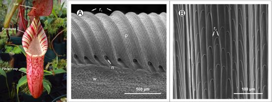
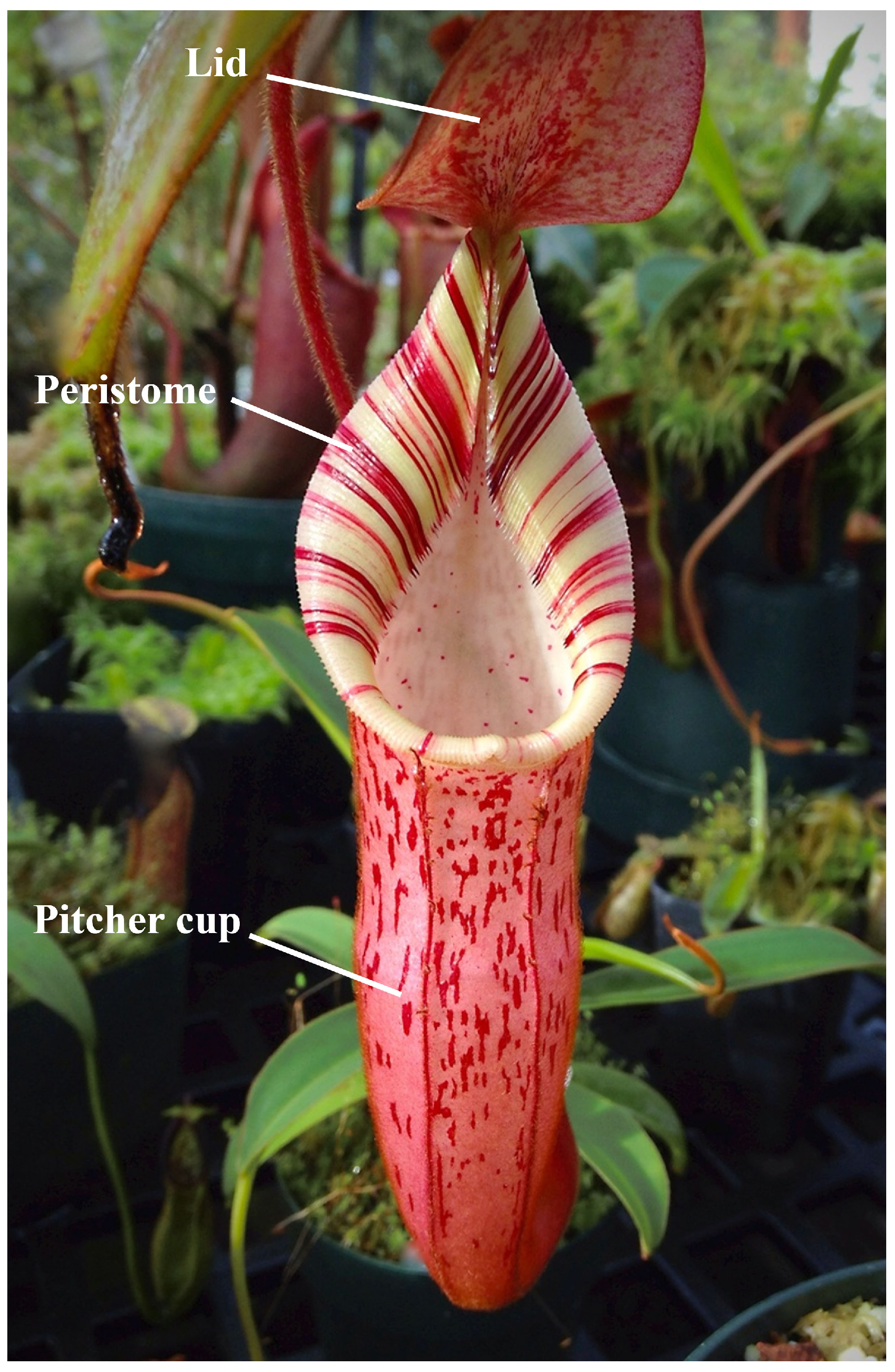
2.2.1. Nepenthes Pitcher Plants

Omniphobic coatings could be classified as slippery surfaces that can repel different types of liquids. Such coatings are exemplified in nature by the Nepenthes pitcher plants (Figure 9). The Nepenthes is a genus of carnivorous plants that are spread in several countries including China, India, Indonesia, Malaysia, and Australia. Nepenthes is also known as tropical pitcher plant or monkey cup. The plant can hold an intermediary liquid (water) by their microstructural roughness distributed on its rim (peristome) surface. The rim is colorful attracting preys such as insects [48]. The liquid is then utilized as a repellent surface to cause the prey to slip into a digestive fluid, which is the plant’s own production of a viscoelastic biopolymers. When the prey stands on the rim, its escape is nearly impossible [49,50]. On top of the plant, there is a lid (operculum), which keeps rain from diluting the digestive fluid in the cup. For some species, there are nectar glands existing underneath the lid to attract preys [51]. There are pores filled with nectar that are spread at the inner edge of the peristome. The plant absorbs nutrients from captured preys through glands that are spread inside the cup.
Figure 9. Nepenthes carnivorous pitcher. Adapted from website [48].
Polymers 06 01266 g009
As seen in Figure 10, the peristome of most Nepenthes species has a highly regular microstructure composed of first- and second-order radial ridges [49,50]. The latter ridges are much smaller and formed by straight rows of overlapping epidermal cells, which step toward inside the pitcher (anisotropic topography). The zone adjoining the peristome toward the pitcher’s inside is covered with waxy crystals. The surface of the epidermal cell is, however, smooth and free of waxy materials.
Microscopic roughness enhances the wetting properties of the peristome surface because of the surface’s hydrophilicity. Moreover, the absence of wax crystals and presence of hygroscopic nectar increase the capillary forces, resulting in rapid spread of water droplets on the surface even against gravitational forces. Thus, under humid conditions, a continuous thin water film completely covers the peristome surface. This film prevents insects from standing on the surface by disabling the adhesion of their pads. Additionally, the anisotropic surface topography prevents interlocking of claws when an insect slips into the pitcher cup [49].
The above examples from plants and animals inspired humans to fabricate several types of slippery surfaces. Those will be discussed in the following section.
Figure 10. (a) Peristome surface (p) of Nepenthes alata, structured by first- (r1) and second-order (r2) radial ridges. In between tooth-like projections at inner edge of the peristome, pores of large extrafloral nectaries (n) can be seen. Below the peristome is wax-covered inner wall surface (w). (b) Second-order ridges (r2) are formed by straight rows of overlapping epidermal cells. From Bauer and Federle [49].
Polymers 06 01266 g010

3. Fabrication of Slippery Surfaces

Hydrophobic surfaces repel water, while omniphobic ones additionally repel many other liquids such as hydrocarbons, crude oil, alcohol, and blood. The solid surface is typically made of or functionalized by low-surface-energy materials such as fluorocarbons or hydrocarbons. The phobicity of both hydrophobic and omniphobic coatings could be intensified by entrapping, respectively, air or lubricating liquid into their microscopic surface textures. For longevity, the entrapped liquid has to be immiscible to the repelled liquid. Submerged omniphobic coatings are therefore purported to maintain their advantage far longer than superhydrophobic coatings. With time, the latter type loses its advantage in part due to the air solubility into the ambient unsaturated water. The diffusion process is accelerated by the convective mass transfer of air into water, which mechanism is significantly more effective in turbulent flows. On the other hand, strong surface tension forces at the microscale work against the diffusion and convective processes, thus improve the surface’s longevity.

3.1. Superhydrophobic Surfaces

3.1.1. Ordered Microtextures

Prior studies demonstrated that superhydrophobic surfaces could be engineered with different textures such as microposts [6] and microridges [52] (Figure 11). The microstructure of these surfaces strongly affects the gas fraction, slip length, drag reduction, and the stability of the air–water interface. For example, in Figure 11a, as post diameter decreases for the same pitch (i.e., distance between two posts), the gas fraction increases, which leads to an increase in the drag reduction and slip length due to the increase of the free-shear area (air–water interface area). However, increasing the gas fraction can jeopardize the stability of the interface. Criteria describing this stability based on roughness design were given by Bico et al. [53]. A similar conclusion can be drawn for microridges.
Figure 11. (a) Scanning electron microscope (SEM) images of post patterns with 50 µm pitch for the displayed inset gas fractions; from Lee et al. [6]. (b) Image of microfabricated surface with microridges, width of cavities and ridges are respectively 30 and 10 µm, depth of rib is 15 µm; from Maynes et al. [52].
Polymers 06 01266 g011
Superhydrophobic surfaces comprised of “nanograss” and “nanobricks” were reported by Henoch et al. [54], see Figure 12. The nanograss surface was reported to yield a contact angle of nearly 180°, and was composed of posts with a diameter of 400 nm and a height of 7 µm spaced 1.25 µm from one another. The nanobricks surface was peculiar because it could better resist elevated hydrostatic pressures due to the effect of entrapped air in its closed cells, which could help to increase the stability of the air–water interface, as will be discussed later in this paper. The size of each cell was 4 µm × 10 µm, the height of the cell walls was about 1 µm, and the wall’s thickness was 300 nm. A surface with a texture somewhat similar to that of the nanograss structure was studied by Choi and Kim [55]. They determined slip length by comparing the measured drag of their surface to that of a smooth one. Lee and Kim [56] demonstrated that slip length could be maximized by superimposing a nanostructure onto sidewalls of a microfabricated structure (Figure 13), similar to the case of wax crystals on papillae of the lotus leaves. The authors demonstrated that the contact angle for their surfaces could approach 180°. In addition, they showed that the slip length could be increased up to 400 µm.
The achieved slip length could be dramatically affected by the mechanical durability of the surface micro/nanoroughness. Mechanical wear on superhydrophobic surfaces results in increased sticking of water drops and loss of nonwettability. Jung and Bhushan [57] showed that a superhydrophobic surface comprised of composite hierarchical structures of carbon nanotubes could sustain mechanical wear due to shear flow much better than the waxy crystals of lotus leaves. Meanwhile, Zhu et al. [58] fabricated a superhydrophobic surface using metal/polymer composite that could better sustain wear under abrasion test. As is well known, superhydrophobicity can be achieved by a combination of well matched low surface energy (chemical hydrophobicity) and roughness. Mechanical wear, on one hand, might remove the thin hydrophobic layer of chemically functionalized rough surface. On the other hand, it could destroy the surface roughness at the micro/nanoscale level. In either case, the surface would lose the nonwetting beneficial effects.
Figure 12. (a) SEM image of silicon nanograss; (b) SEM image of silicon nanobricks. From Henoch et al. [54].
Polymers 06 01266 g012
Figure 13. (a) Nanostructures on the sidewall; (b) re-entrant structure. From Lee and Kim [56].
Polymers 06 01266 g013

3.1.2. Engineered Cost-Effective Surfaces

There are limitations for commercializing microfabricated surfaces such as those shown in Figure 11, Figure 12 and Figure 13. Production cost is probably prohibitive when microfabricated surfaces are for large-scale applications. Recent studies, however, have shown that there are alternative methods for engineering affordable superhydrophobic surfaces. One can produce a superhydrophobic surface by randomly depositing hydrophobic aerogel particles on a substrate [59,60,61]. Samaha et al. [62] prepared aerogel superhydrophobic surfaces with different particle sizes. Aerogel beads made of amorphous silicon dioxide having almost 99.8% porosity were ground and filtered through four stages of sieves with mesh sizes of 43, 104, 150, and 210 µm to prepare four categories of aerogel particles. From each category, aerogel particles were deposited onto a metallic substrate coated with a thin polymer film for adhesion. Figure 14 shows SEM images of four aerogel coatings with different particle-size ranges. The inset in the figure shows a water droplet on each coating with a static contact angle of 155° or higher, and an average contact-angle hysteresis of about 3°, demonstrating each coating’s superhydrophobicity. As seen in parts b, c and d of the same figure, few particles exist with sizes smaller than the prescribed range determined from the mesh size of a particular sieve. The electrostatic charge of the particles is responsible for attracting few particles to each other, and therefore giving the particle conglomerate a larger virtual size. The deposited particles provide the surface roughness and porosity necessary to entrap air before the surface is submerged in water. As water flows over the coating, the interface between the entrapped air and the water has very low skin friction, resulting in slip flow and drag reduction.
Figure 14. SEM images of superhydrophobic aerogel coatings with different particle-size ranges. (a) 0–43 µm; (b) 43–104 µm; (c) 104–150 µm; (d) 150–210 µm. Upper right inset in each figure shows a water droplet on top of the particular coating. From Samaha et al. [62].
Polymers 06 01266 g014
Electrospinning is a second cost-effective fabrication technique that can be used to produce superhydrophobic surfaces with fibrous microstructure. This technique can be used to deposit micro- and/or nanotextured coatings by spinning hydrophobic polymers (e.g., Polystyrene) onto substrates of arbitrary geometries [63,64,65,66], as shown in Figure 15. Conventionally, electrospinning was performed by applying a large DC-potential between the electrospinning source (typically a hypodermic syringe) and the substrate, resulting in nonwoven fiber mats with randomly oriented fibers [67]. The random orientation of the fibers resulted from the inherent electrostatic instability of the charged jet as it traveled from the spinneret to the collector. This instability could be reduced by using a DC-biased AC potential that induced short segments of alternating polarity, thereby reducing the magnitude of the destabilizing force on the fiber as seen in Figure 16a.
Figure 15. Schematic illustration of electrified polymer jet during DC-biased AC-electrospinning. From Ochanda et al. [66].
Polymers 06 01266 g015
Figure 16 shows SEM images of fiber mats produced via DC-biased AC-electrospinning, which provided a better control over the microstructure of deposited fibrous mats. The inset in Figure 16b shows a water droplet on the coating with a static contact angle of 157°, proving superhydrophobicity even in the case of random fiber deposit [66]. Similar to the case of microfabricated surfaces, fibrous coatings can provide the porosity that is necessary to entrap air when the surface is immersed in water. When water flows over such a surface, a reduction in skin friction is observed [20]. Two recent reviews [68,69] discussed several techniques to develop superhydrophobic and oleophobic fibrous surfaces using electrospinning methods. Random, aligned, and spider-web-like nanofiber/net structures can be produced. Furthermore, by controlling the electrospinning processing parameters, more complicated morphologies can be achieved such as ribbon-like, core–shell, helical, rice-grain shape, porous, single nanofibers with bead-on-string, hollow, multichannel tubular, necklace-like, tube-in-tube, and nanowire-in-microtube structures. Those reviews highlighted the recent developments to enhance the mechanical properties (tensile strength) of the electrospun fibrous coatings inspired by silver ragwort leaves. They also discussed coatings inspired by water strider’s legs, goose feathers, lotus and rice leaves, etc.
Figure 16. SEM images of 18% weight Polystyrene fibers with 1% weight fluoro-elastomer. (a) Grid-like structure of a mono-layer; (b) Several layers of fibers show random orientation. Upper right inset in (b) shows a water droplet on top of this particular coating. Adapted from Samaha et al. [20].
Polymers 06 01266 g016
The morphology of the fibers influences the surface’s hydrophobicity. For example, fiber diameter can affect the static contact angle, as shown in Figure 17. The figure shows the results for produced beaded and bead-free fibers. It shows that contact angle decreases with increasing fiber diameter. Note, however that since other microstructural parameters of the surfaces reported were not kept constant while fiber diameter was varied, changes in the fiber diameter could affect the porosity of the mat. Therefore, in the absence of more microstructural information, one should refrain from directly relating fiber diameter to contact angle. Beaded fibers or polymeric microdroplets could appear during electrospinning if the polymeric fluid did not have adequate viscoelasticity and conductivity, which led to Rayleigh instability, i.e., domination of surface tension during the process that tended to break the liquid into droplets. In a related experiment, a recently developed method to produce a hierarchical rough superhydrophobic surface was developed by Laird et al. [70]. Carbon-based nanomaterials (nanohybrid shish kebab structure) was functionalized by polytetrafluoroethylene (PTFE) using vapor deposition technique. The morphology was adapted to control the surface superhydrophobicity using induced electric field. Application of electric potential on the nanostructures allowed reversible wetting transition of surface.
Figure 17. Effect of fiber’s diameter on static contact angle. From Ma et al. [63].
Polymers 06 01266 g017

3.2. Fabrication of Omniphobic Surfaces

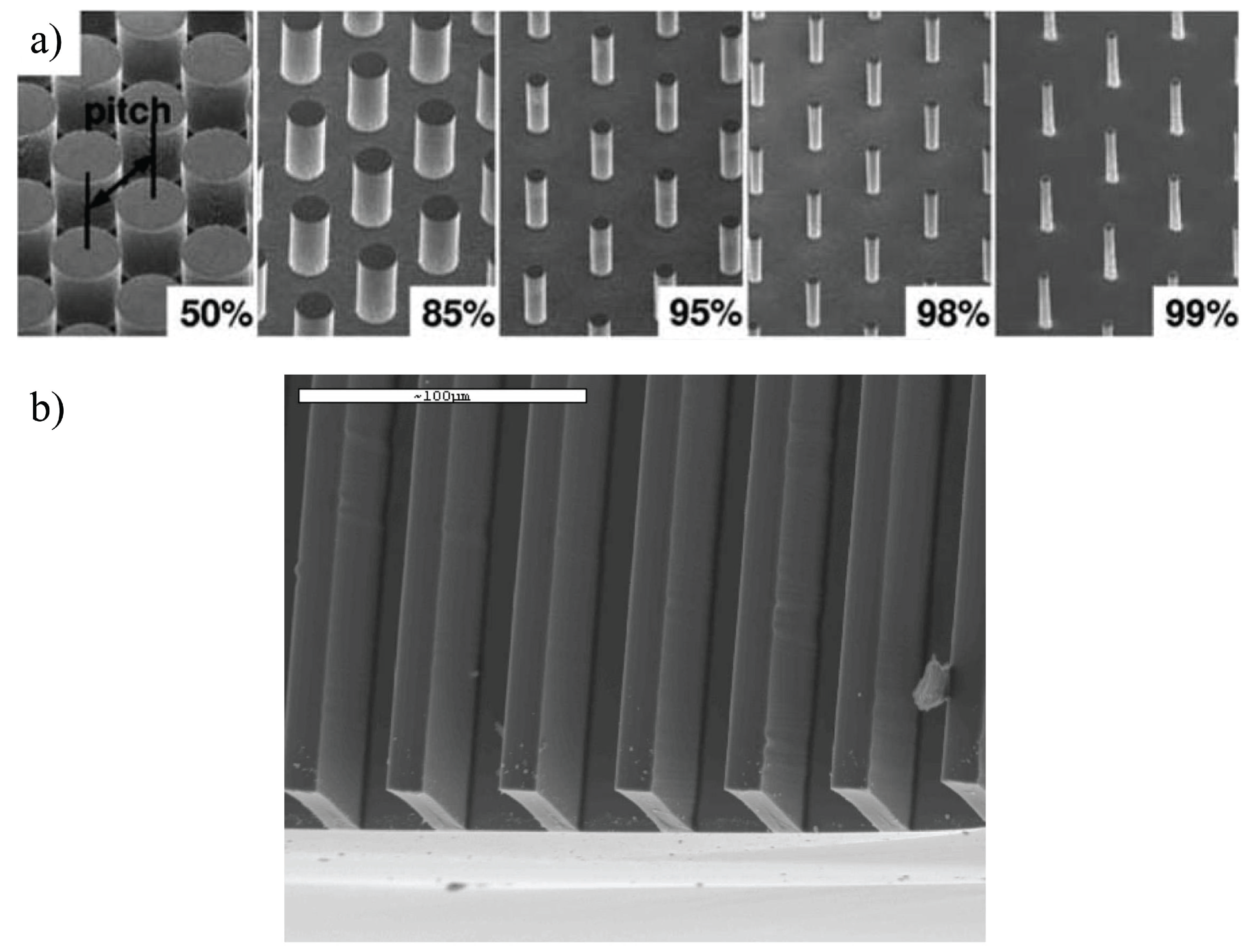
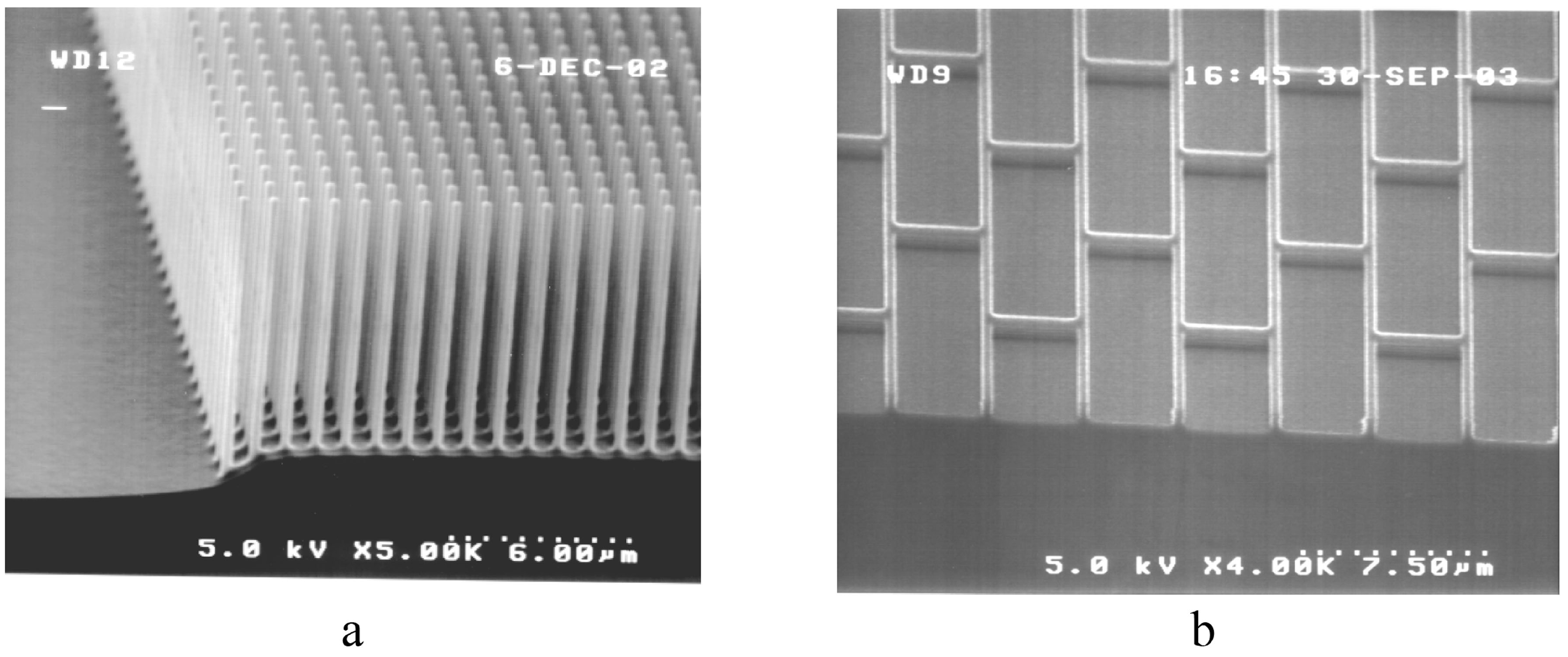
3.2.1. Superoleophobic Surfaces
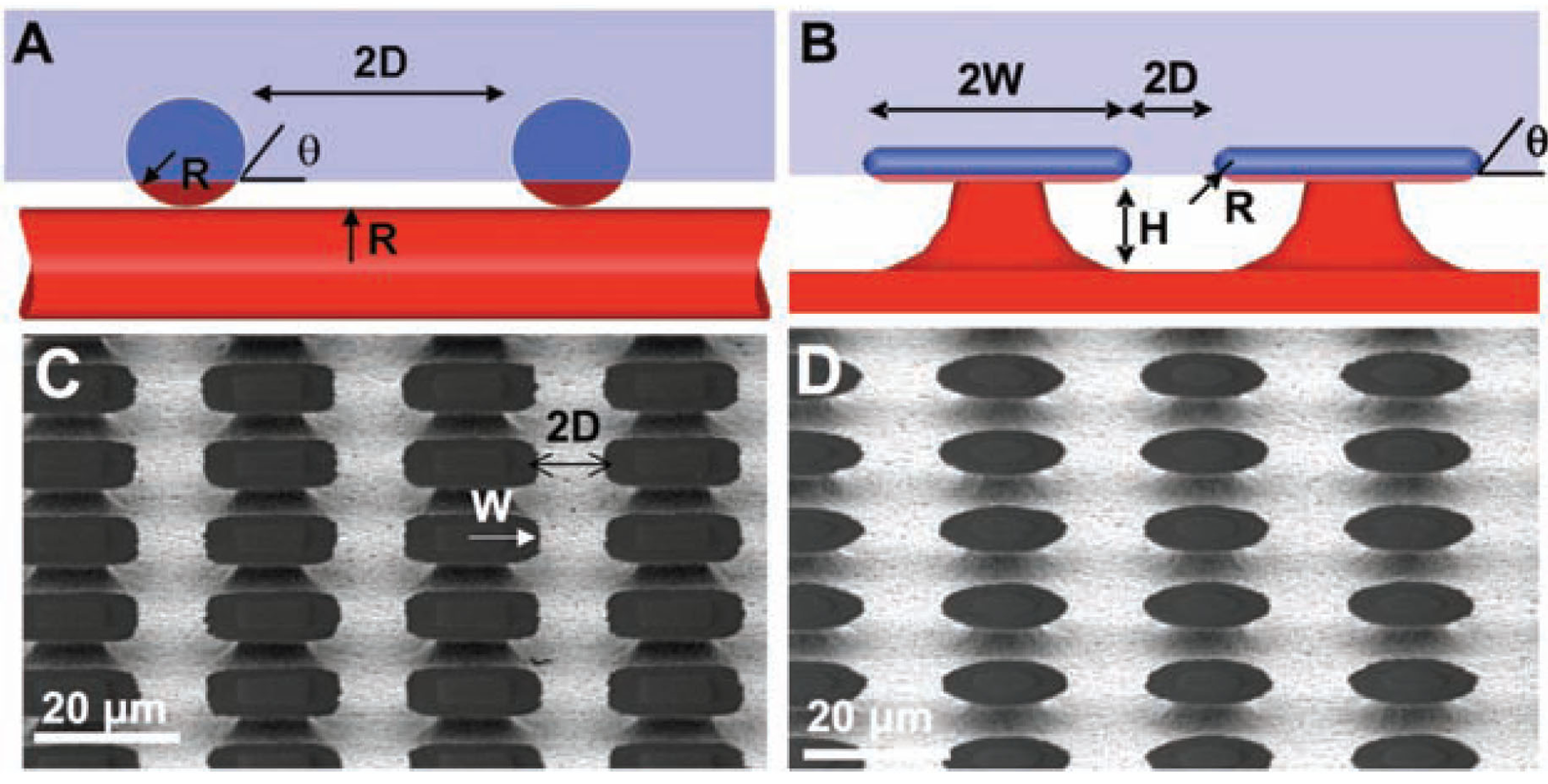
By entrapping air into their micropores, superoleophobic coatings could be classified as slippery surfaces that have the ability to repel different liquids with significant low surface tension such as hexadecane, dodecane, octane, and ethylene glycol. Superoleophobicity could be achieved by a combination of surface topography, low surface energy, and local curvature of the surface microsrtucture (re-entrant geometry). Tuteja et al. [22] fabricated surfaces having concave microtopographic features, as shown in Figure 18. They demonstrated that there are two important design parameters to achieve superoleophobicity. For electrospun fibers, the first parameter is the spacing ratio D* = (R + D)/R, where R is the radius of the fibers, which influences the solid area fraction ϕs and the apparent contact angle. The second is the robustness parameter H* = 2(1 cos θ)Rlcap/D2, where lcap = (γlv/ρg)1/2, and γlv is the liquid–vapor surface tension. The parameter H* evaluates the resistance to wetting transition—robustness of the metastable Cassie state—with respect to fluid properties, equilibrium contact angle, and surface geometry. Both parameters D* and H* should be much bigger than one to get a surface with strong resistance to wetting transition. The other proposed superoleophobic texture is the so-called “microhoodoo geometry” in which the re-entrant curvature was engineered on the side walls under microcaps (Figure 18B). For this geometry, the design parameters take the form D* = [(W + D)/W]2 and H* = 2[(1 cos θ)R + H]lcap/D2.
A cost-effective simpler technique to prepare superhydrophobic and superoleophobic microstructured coating was described by Srinivasan et al. [71,72]. They sprayed a solution of poly(methyl methacrylate) (PMMA) and the low surface energy molecule 1H,1H,2H,2H-heptadecafluorodecyl polyhedral oligomeric silsesquioxane (fluorodecyl POSS) using an air brush with a pressurized nitrogen stream. The air brush had a nozzle diameter of 0.75 mm, and was connected to a compressed nitrogen tank at 170 kPa to spray coat the polymer solution at a distance of l = 20–30 cm from the substrate. The authors demonstrated that the distance l doesn’t have a significant effect on the morphology of the coating. Meanwhile, the solution concentration and molecular weight of the dissolved polymer significantly influence the characteristics of the coating microstructure, as shown in Figure 19. The POSS/PMMA solute concentration was adjusted at 15, 25 and 50 mg/mL at a fixed fraction of 50 wt% fluorodecyl POSS. Additionally, the total mass of the polymer blend delivered to each surface was adjusted to remain constant by controlling the spray duration. The figure shows that the silicon substrate is completely covered by a corpuscular layer of spherical microbeads about 20 µm in diameter at 15 mg/mL solute concentration. A transition to a beads-on-string morphology occurs at a concentration of 25 mg/mL. Nanofibers were developed with beads of diameter ranging from 20 to 50 µm. At the higher solute concentrations of 50 mg/mL, a dense fibrous mesh is produced with individual strands forming bundles of locally oriented fibers. The corpuscular structures possess slightly higher advancing and receding contact angles than other textures.
Another example of omniphobic coatings is the slippery liquid-infused porous surfaces. Such coatings were engineered to possess certain benefits, as explained in the next subsubsection.
Figure 18. Critical role of re-entrant curvature. (A) and (B) Cartoons highlighting the formation of a composite interface on surfaces with re-entrant topography, for both fibers and microhoodoos. The geometric parameters R, D, H, and W characterizing these surfaces are also shown. The blue surface is wetted while the red surface remains unwetted when in contact with a liquid whose equilibrium contact angle is θ < 90°. (C) and (D) SEM micrographs for two microhoodoo surfaces having square and circular flat caps, respectively. The samples are viewed from an oblique angle of 30°. From Tuteja et al. [22].
Polymers 06 01266 g018
Figure 19. (a) Scanning electron microscope images of silicon surfaces sprayed with 50/50 wt% PMMA/fluorodecyl POSS blends (B2; Mw = 593 k, PDI = 2.69) of differing solute concentrations as indicated. (b) Droplets of water (15 µL) on each of the morphologies with corresponding values of apparent advancing Polymers 06 01266 i008 and receding Polymers 06 01266 i009 contact angles. From Srinivasan et al. [71].
Polymers 06 01266 g019

3.2.2. Slippery Liquid-Infused Porous Surfaces (SLIPS)

The slippery liquid-infused porous surfaces (SLIPS) were inspired by the Nepenthes pitcher plants. These surfaces were demonstrated to possess advantages of self-healing following physical damage within 0.1–1 s, pressure stability up to about 680 atm, and maintaining low contact-angle hysteresis <2.5° [31]. SLIPS were engineered to hold an intermediary infused liquid lubricant such as 3M Fluorinert FC-70 or DuPont Krytox oils in a fluorinated microstructural roughness, as shown in Figure 20a. The oil is utilized as a repellent surface for different kind of liquids such as water, blood, crude oil, alcohols, etc. This, in turn, could cause slip effect. Engineered omniphobic surfaces could be produced using microfabrications of ordered or disordered roughness. However, the well-matched surface energies of the lubricant and the solid rough surface is crucial [31]. The lubricant should not only wet within the substrate roughness but also be more wetting of the solid than the other liquid needed to be repelled (Figure 20b). Also, both liquids must be immiscible. The properties of such coatings are not sensitive to the precise micro/nanostructures of the surface, making the preparation technique cost-effective, for example for the Teflon membrane (shown in Figure 20c) and the porous polyelectrolyte multilayers [73]. Additionally, surfaces with functionalized ordered microstructures such as microposts could also be used as a substrate to prepare SLIPS. The effectiveness of the resulting coating to repel low-surface energy liquids such as Hexane is shown in Figure 20d where the sliding contact angle could be as low as 3°. Shillingford et al. [74] demonstrated that fabrics such as cotton and polyester could be treated to become SLIPS. Thus, the treated materials could be used as stain-free fabrics since they could repel even low-surface-tension liquids.
In the next section, we discuss the characterization of different manmade slippery surfaces.
Figure 20. Design of SLIPS. (a) Schematics showing fabrication of SLIPS by infiltrating functionalized porous/textured solid with a low-surface energy, chemically inert liquid to form a physically smooth and chemically homogeneous lubricating film. (b) Comparison of stability and displacement of lubricating films on silanized and non-silanized textured epoxy substrates. Top panels show schematic side views; bottom panels show time-lapse optical images of top views. Dyed pentane was used to enhance visibility. (c) Scanning electron micrographs showing the morphologies of porous/textured substrate materials: an epoxy-resin-based nanofabricated post array (left) and a Teflon-based porous nanofibre network (right). (d) Optical micrographs demonstrating mobility of low-surface-tension liquid hydrocarbon—hexane (γ = 18.6 ± 0.5mN m−1, volume of about 3.6 mL)—sliding on a SLIPS at low angle of 3°. From Wong et al. [31].
Polymers 06 01266 g020

4. Characterization of Slippery Surfaces

4.1. Superhydrophobic Surfaces

4.1.1. Slip Flow and Drag Reduction

When a superhydrophobic surface is submersed in water, it generates slip flow, which reduces the skin-friction drag exerted on the surface. Drag is the force produced by a fluid to resist the relative motion of a solid. A tremendous amount of fuel is consumed each year both by air and water vehicles and by gas and liquid transmission through pipelines in order to overcome drag [75]. Drag force can be classified into two main categories, form (pressure) drag and skin-friction drag. The latter, which depends on fluid viscosity, strain rate, and surface area, is the subject of this section. The multiplication of fluid viscosity and velocity gradient gives the shear stress. Figure 21 shows a Couette flow between two plates having a gap h in the normal direction z. The upper plate is moving with velocity Vavg and the lower one is stationary. The lower plate can have a no-slip (sticky) or a slip boundary condition. In the case of no-slip boundary, the slope of the velocity gradient (line S1) is higher than that of slip flow (line S2), which leads to a higher shear stress.
Figure 21. Schematic diagram of velocity profiles between fixed and moving plates in case of slip and no slip at fluid-solid interface. From Samaha et al. [76].
Polymers 06 01266 g021
Generally, slip is defined as a fluid dynamics condition that there is a relative tangential velocity between the solid surface and the fluid immediately adjacent to the surface. For gas flow, slip could occur if the mean free path of the gas (i.e., the average distance traveled by molecules between collisions) is comparable to the characteristic dimensions of the flow [77]. For superhydrophobic coatings, air is entrapped in the surface’s pore space producing two different interfaces. One is the aforementioned air–water interface on which water slips, and the other is the solid–water one to which water sticks. The average slip over the entire surface is often referred to as “effective slip” [78]. The air–water interface area is characterized by gas fraction, which significantly influences the superhydrophobicity of the surface. Callies et al. [4] experimentally demonstrated that as gas fraction increases, static contact angle increases. Furthermore, the gas fraction has an impact on the so-called “slip length, δ” [6]. According to Navier’s model [19], the magnitude of the slip velocity is proportional to the magnitude of the strain rate. The slip length is the proportionality constant as shown in Figure 21. Thus, the slip length can be calculated from
Polymers 06 01266 i001
where Uslip is the area-weighted average slip velocity at the superhydrophobic wall, u is the streamwise velocity, and y is the normal direction.
Several studies have demonstrated the effect of gas fraction on the slip length [5,6,52,79,80,81,82,83,84,85,86,87,88]. For laminar flow, slip length increases with gas fraction (Figure 22) and hence from Equation (1), velocity gradient decreases (i.e., less drag). The figure shows the calculated and measured slip lengths (normalized by the pitch; the distance between two posts) versus gas fraction for ordered microposts on a superhydrophobic surface. A closer view at gas fractions below 0.6 and above 0.85 is given in the insets for better illustration. From the figure, it is obvious that when the gas fraction, ϕg, is less than 0.4, the slip length is proportional to Polymers 06 01266 i002
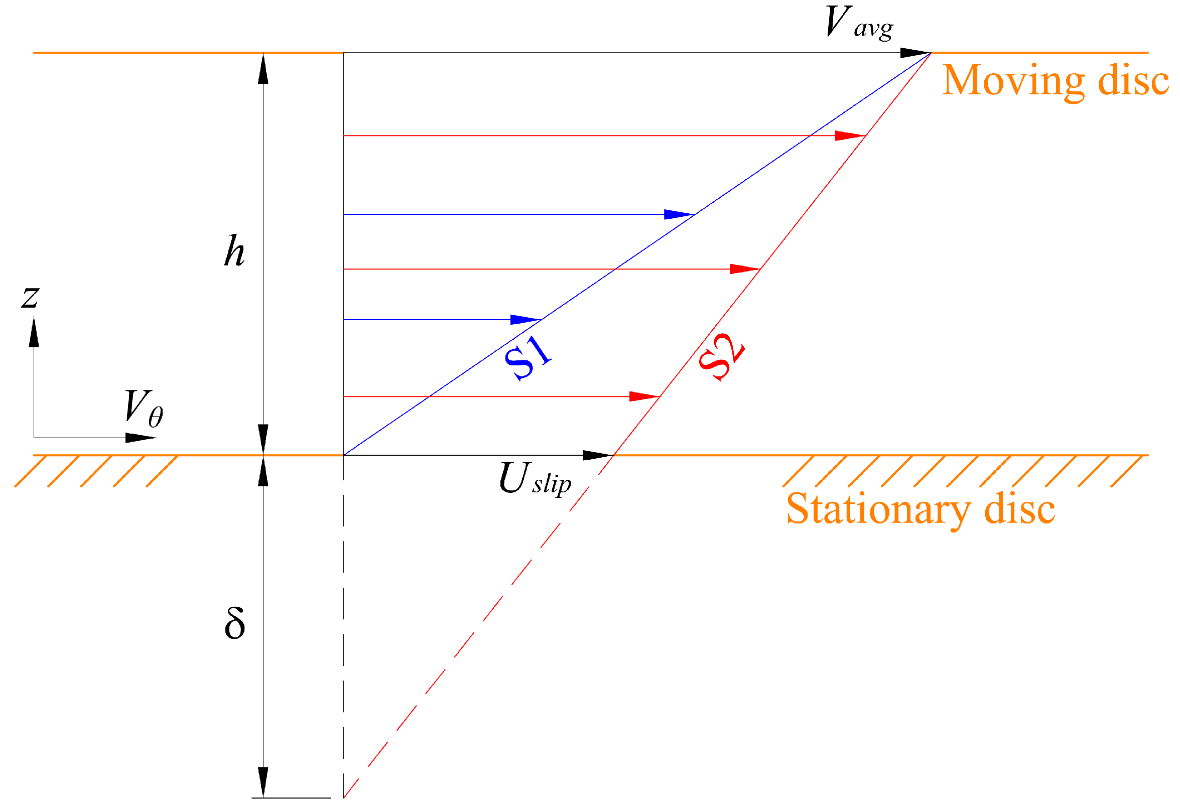
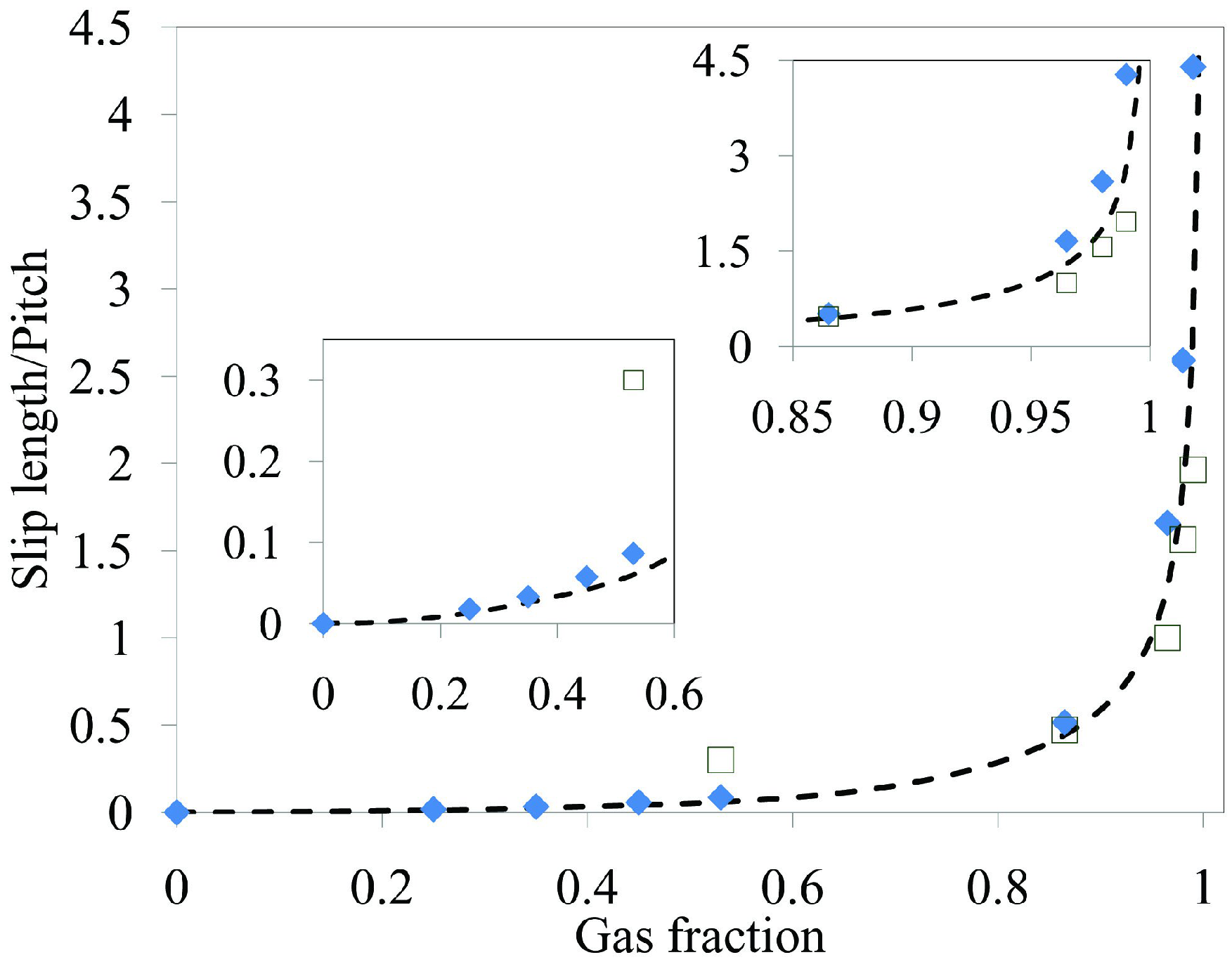
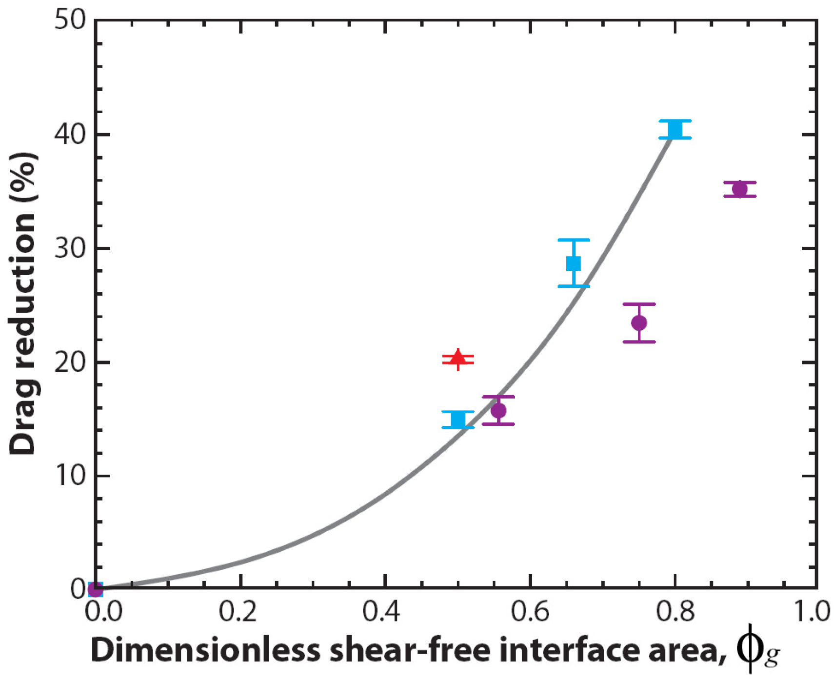
. Meanwhile, if the gas fraction is higher than 0.7, the slip length is proportional to Polymers 06 01266 i003
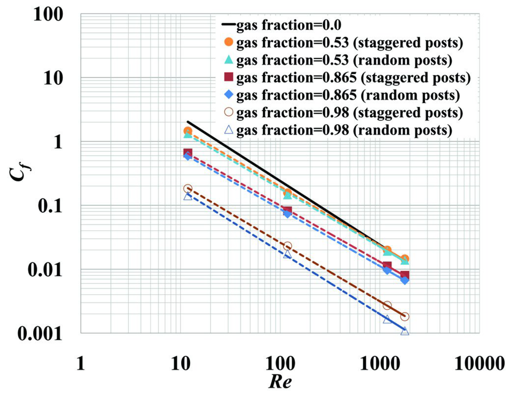
. Within the range 0.4 < ϕg < 0.7, interpolation is utilized. The above mathematical proportionalities were derived and validated by Ybert et al. [83]. The drag reduction also increases as gas fraction increases, as shown in Figure 23. The figure includes both experimental and numerical results for a microchannel with a microridged superhydrophobic wall.
Figure 22. Slip length versus gas fraction obtained for laminar flow over ordered microposts superhydrophobic surface. Experimental data of Lee et al. [6] (open squares), theory of Ybert et al. [83] (dashed line), and numerical results of Samaha et al. [79] (solid diamonds).
Polymers 06 01266 g022
Figure 23. Average drag reduction as a function of dimensionless shear-free area, gas fraction. Measurements for 30 µm wide microridges spaced 30 µm apart (red triangles), 20 µm wide microridges spaced 20 µm apart (blue squares), and 30 µm square microposts spaced 30 µm apart (purple circles). Numerical results for 20 µm wide microridges spaced 20 µm apart (gray line). From Rothstein [10].
Polymers 06 01266 g023
Samaha et al. [79] simulated the performance of superhydrophobic surfaces having idealized random roughness (posts or particles) and compared their results with those of surfaces with staggered posts. Their numerical simulations indicated that the gas fraction has a significant impact on the characteristics of a superhydrophobic surface, as it affects the slip length and therefore the skin-friction coefficient. As seen in Figure 24, the friction coefficient decreases with increasing gas fraction for surfaces with both staggered posts and randomly distributed posts. In addition, the difference between the skin-friction coefficient of the random posts and that of the staggered posts increases with gas fraction. Thus, the surface with randomly distributed posts possesses better drag reduction than that of staggered ones.
Figure 24. Skin-friction coefficient versus Reynolds number (Moody diagram) for different gas fractions. From Samaha et al. [79].
Polymers 06 01266 g024
Other studies showed that for turbulent flows, increasing the gas fraction results in an increase in the slip velocity and drag reduction [85,86,87]. Figure 25 shows that skin-friction coefficient decreases by utilizing a superhydrophobic surface on one or both walls of a microchannel for a range of Reynolds numbers covering both the laminar- and turbulent-flow regimes. However, Woolford et al. [88] demonstrated that in a turbulent flow regime, streamwise ridges (i.e., flow direction is parallel to microridges structure) could cause drag reduction, while spanwise ridges (i.e., flow direction is perpendicular to microridges) could increase the drag. Obviously, the influence of the microstructural parameters of a superhydrophobic surface on its performance requires further exploration. Such surfaces could be utilized as a passive method of flow control and might potentially become a viable alternative to the more complex and energy consuming active or reactive methods of flow control such as wall suction/blowing [75]. However, there is another coating’s characteristic that also could affect the application of such surfaces, that is the stability of the air–water interface.
Figure 25. Skin-friction coefficient vs. Reynolds number. Measurements for microchannel with smooth surfaces (open triangles and open stars), with single superhydrophobic wall (solid circles), and with two superhydrophobic walls (open circles and solid squares). The theoretical predictions of the friction coefficient for a smooth channel are also shown (—). From Daniello et al. [85].
Polymers 06 01266 g025

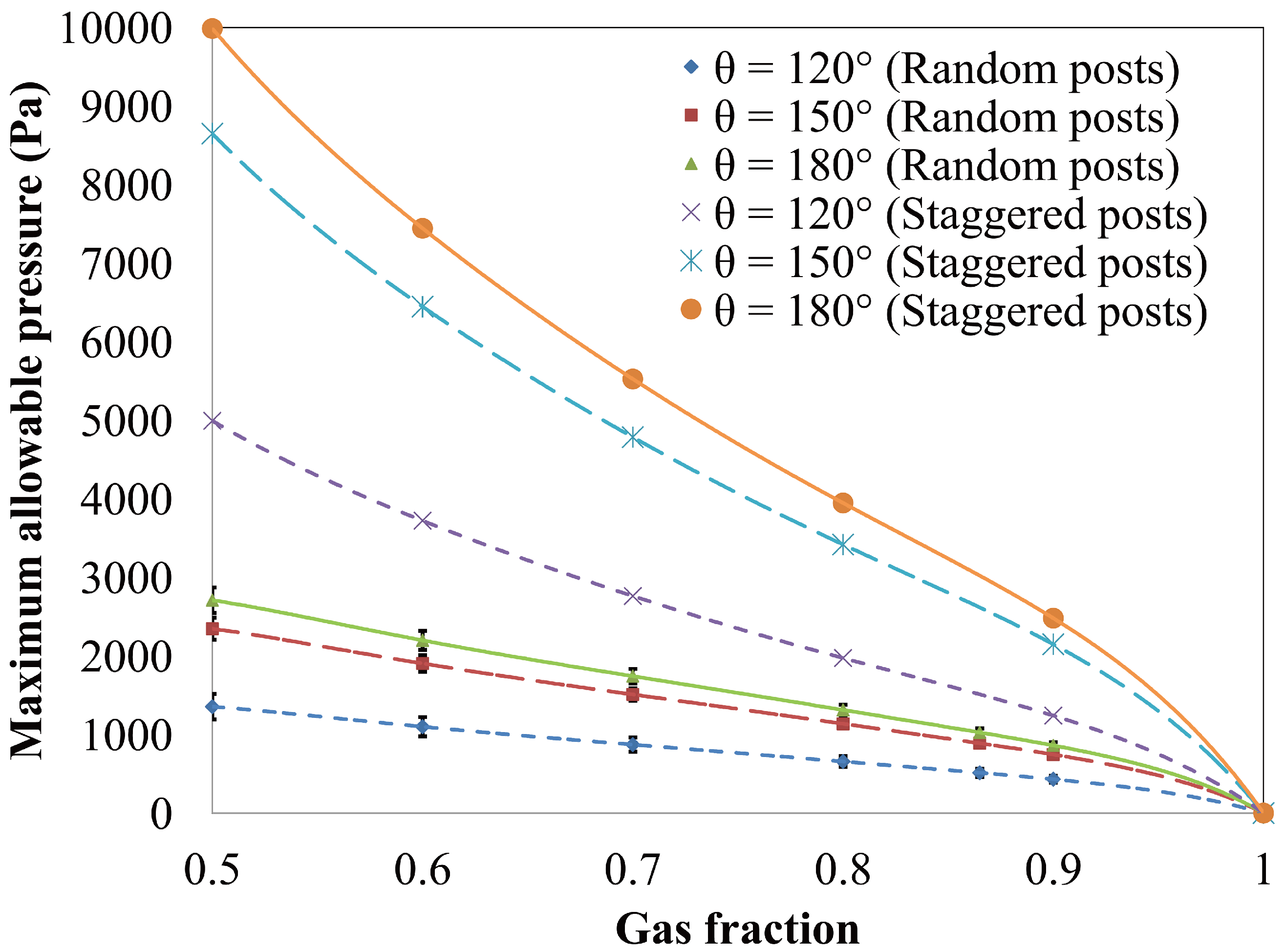
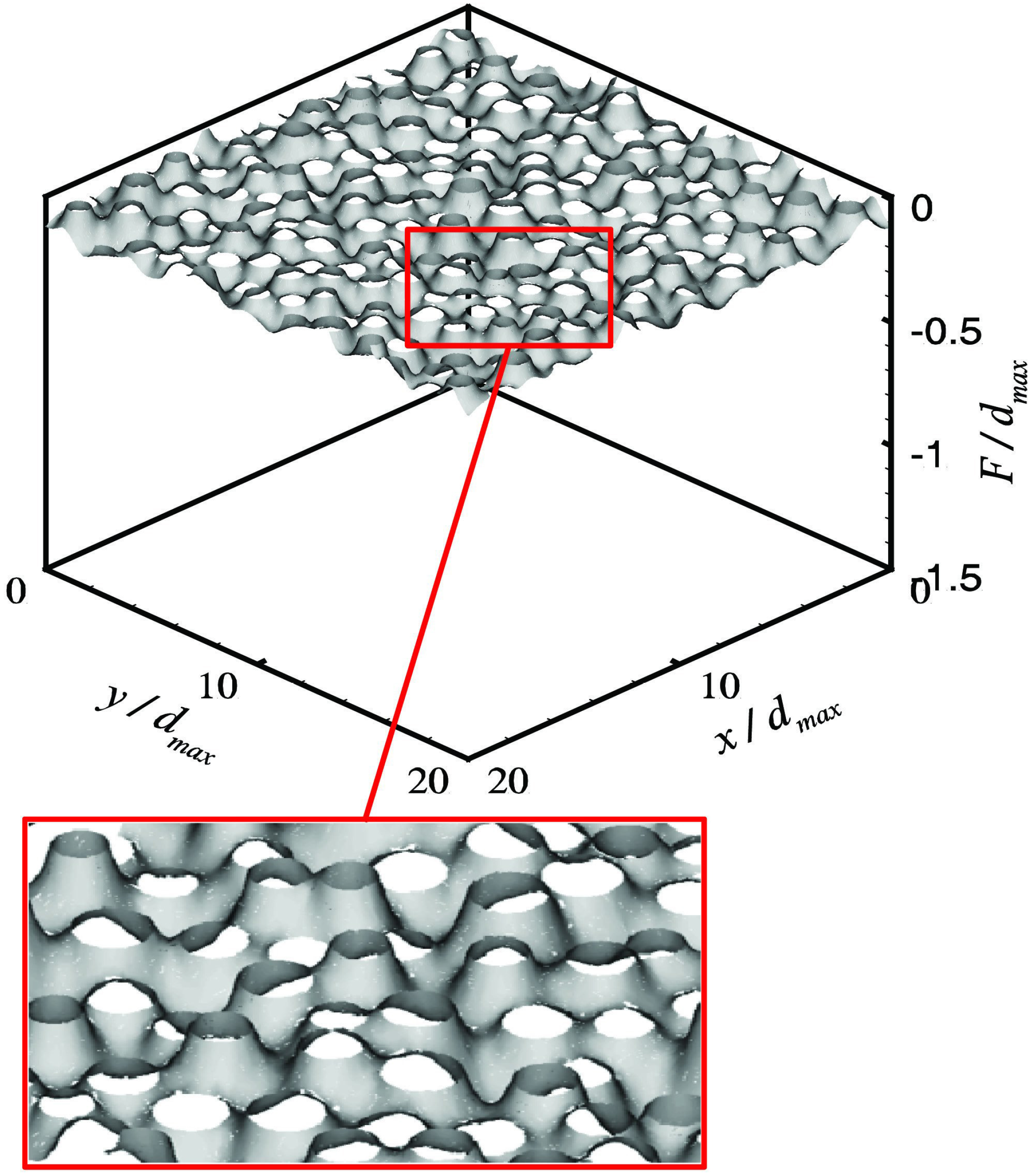
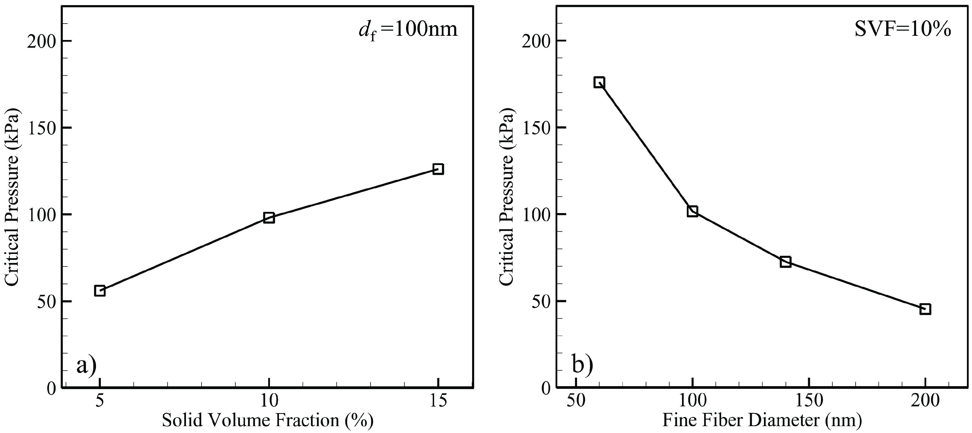
4.1.2. Air–Water Meniscus Stability Under Hydrostatic Pressure

The air–water interface developed due to superhydrophobicity is, for example, the surface that supports a water strider’s weight. Under stability condition, surface tension force is developed on the interface to support the load. A similar force can be exerted on the interface formed over a submerged superhydrophobic surface by the column of water above the surface. If the pressure is sufficiently high, water will penetrate into the micropores of the surface and replace the air, i.e., transition from the non-wetted (Cassie) to the wetted (Wenzel) state. The transition is interpreted by two approaches: one based on minimizing the thermodynamic free energy [89,90], and the other using a balance of forces across the interface [91,92,93]. Lee and Kim [56] used the latter to develop an equation to determine the maximum allowable hydrostatic pressure (critical pressure) in terms of the surface microstructure for aligned or staggered arrangement of posts as expressed by the following equation:
Polymers 06 01266 i004
where Pmax is the critical pressure, the pressure above which the system departs from the Cassie state, ϕg is the gas fraction, γ is the surface tension of the liquid, θ is the contact angle, and L is the pitch (distance between two posts).
Samaha et al. [79] utilized a Voronoi diagram [94] to determine the local gas fraction and the maximum pitch for superhydrophobic surfaces made up of randomly distributed posts. This information was used in Equation (2) to determine the maximum allowable hydrostatic pressure, which corresponds to the post that has the maximum local gas fraction. In a Voronoi diagram, the superhydrophobic surface is divided into cells, as shown in Figure 26. Each post, represented by a number, has a single surrounding Voronoi cell consisting of all points on the surface that are closer to that post than to any other post. The sides of a Voronoi cell are the locations of the points on the surface that are equidistant from the two nearest posts. The Voronoi nodes are the points equidistant from three (or more) posts. Note that a Voronoi diagram provides a rational tool to compute the local gas fraction and maximum pitch when dealing with random posts.
Figure 26. Voronoi diagram obtained for randomly distributed posts. The numbers shown in this figure refers to the posts and their locations. From Samaha et al. [79].
Polymers 06 01266 g026
The maximum allowable pressures for surfaces comprised of random and staggered posts were compared with each other as shown in Figure 27. The maximum allowable pressure decreases dramatically when the posts are arranged randomly. The results of this figure indicate that superhydrophobic surfaces with random roughness are more susceptible to failure under hydrostatic pressures. Therefore, although utilizing random posts structure could cause a better drag reduction (Figure 24), the air–water interface would be more likely to fail under elevated pressures.
Figure 27. Maximum allowable pressure as function of gas fraction and contact angle for both random and staggered posts. From Samaha et al. [79].
Polymers 06 01266 g027
Emami et al. [59] conducted a similar study in 3-D space. In particular, they simulated the stability of air–water interface formed on granular superhydrophobic coatings comprised of randomly distributed spherical aerogel particles in comparison to the ordered distributed ones. The authors also conducted a series of 3-D full-morphology (FM) numerical simulations and analytical expressions to predict the critical pressure against the solid volume fraction of their granular porous coatings, as shown in Figure 28. The figure shows that the air–water interface could sustain more pressure as the solid volume fraction increases. Moreover, the surface with random particles is more susceptible to fail under hydrostatic pressure.
In another paper, Emami et al. [95] developed a mathematical framework to predict the shape and stability of the air–water interface of superhydrophobic surfaces comprised of randomly distributed posts of different diameters, heights, and materials. They used the Young–Laplace equation to derive a second-order partial differential equation that was solved numerically via finite element method. Figure 29 shows an example of an air–water interface formed over a surface comprised of randomly distributed posts with diameters of 8 to 12 µm and heights of 50 to 51 µm. The deflection of the meniscus was calculated at a hydrostatic pressure of 3400 Pa.
Figure 28. Numerically and analytically calculated critical pressure against solid volume fraction for ordered aerogel particles and random ones. Figure adapted from Emami et al. [59].
Polymers 06 01266 g028
Figure 29. Calculated meniscus surfaces for superhydrophobic surface with randomly distributed posts of random diameters and heights at P = 3400 Pa. Term dmax refers to maximum post’s diameter. Terms x, y, and F are Cartesian coordinates. Figure adapted from Emami et al. [95].
Polymers 06 01266 g029
.
In a related numerical study, Bucher et al. [96] conducted a series of FM simulations to study the stability of an air–water interface formed over superhydrophobic coatings composed of randomly oriented nanofibers. The study was achieved for 3-D virtual domains resembling the internal microstructure of electrospun fiber mats. Figure 30 shows an example of the simulations at two different hydrostatic pressures. The solid volume fraction and fiber diameter are 10% and 500 nm, respectively. It is obvious that by increasing the pressure, the water (red color) fills a greater fraction of the pore space. Figure 31 shows the determined critical pressure as a function of the coating’s morphology for bimodal fibrous media, composed of two different fiber diameters. The surface’s morphology is characterized by the solid volume fraction and fine fiber diameter, df. The figure also shows that the critical pressure increases with increasing solid volume fraction or fine fiber diameter, when other microstructural parameters are held constant. Similar work was previously reported [97,98] to simulate the fluid transport phenomena in porous media, but by using the lattice Boltzmann technique. Water intrusion through a permeable material was modeled at different capillary pressures. This work is more applicable for electrolyte fuel cells.
Figure 30. visualization of two stages of water intrusion into unimodal fibrous structure with random in-plane fiber orientation using full morphology method at two different pressures. (a) 58.983 kPa; (b) 77.333 kPa. Non-wetting fluid (water) represented in red region is made up of spheres fitted into the domain. Figure adapted from Bucher et al. [96].
Polymers 06 01266 g030
Figure 31. Critical pressure predictions for layered, randomly oriented media compared against variations in one of four microstructural parameters. (a) Solid volume fraction; (b) fiber diameter. For both (a) and (b), coarse-to-fine fiber diameter ratio (Rcf) = 5 and coarse number fraction (nc) = 0.1. Figure adapted from Bucher et al. [96].
Polymers 06 01266 g031
Other studies were performed to determine the meniscus shape of different surfaces’ morphologies at different pressures [99,100]. Meanwhile, Extrand [101] developed a mathematical model to determine the critical pressure of a superhydrophobic surface comprised of microstructure roughness, which is superimposed with a nanostructure one. Such a surface resembles the features of lotus leaves. Extrand’s model demonstrated that the nanostructure roughness enhances the hydrophobicity of the surface. In a related experimental study, Sheng and Zhang [102] demonstrated the effect of elevated pressures on the superhydrophobicity of lotus leaves by measuring contact angles of droplets beading on the leaves before and after exposing them to pressures.
Stability of air–water interface of superhydrophobic surfaces comprised of random roughness could also be characterized by the so-called “terminal pressure”. The pressure beyond which the surface undergoes a global transition from the Cassie state to the Wenzel state [62], and therefore could no longer generate drag reduction. Note that the terminal pressure differs from the critical pressure. The latter is the pressure above which the surface starts transitioning from the Cassie state but not necessarily globally reaching the Wenzel one. In other words, the critical pressure is lower than the terminal one for a surface with random roughness. However, both pressures are equal in case of a surface with ordered roughness. The authors performed their measurements on cost-effective granular (aerogel) superhydrophobic surfaces shown in Figure 14. In order to provide an estimate for the gas area fraction of the coatings, an image processing technique was developed and validated. Thresholding (segmenting) the SEM images was processed to distinguish the upper surfaces of the particles from the background. Through this process, the gray levels were split into two classes in an attempt to separate the objects of interest from the background, and to prepare the images for analysis.
Figure 32 shows the thresholded images of those shown in Figure 14. The white regions represent the upper areas of the particles that could be in contact with water when the surface is submerged. This was estimated by calculating the total area covered with white pixels. Meanwhile, the black regions represent the voided locations in which air is entrapped. The ratio of the black area to the total one represents the gas area fraction. The segmentation process was performed using Ostu’s algorithm [103] in which the gray levels of the original image are split into two classes at the optimum thresholding value at which the intra-class variance of both classes is minimal.
Figure 32. Thresholded SEM images of superhydrophobic aerogel coatings with different particle-size ranges. (a) 0–43 µm; (b) 43–104 µm; (c) 104–150 µm; (d) 150–210 µm. From Samaha et al. [62].
Polymers 06 01266 g032
The stability of the meniscus (air–water interface) was evaluated by measuring the pressure needed for wetting transition using a developed optical technique and a custom-built pressure vessel [20], which is explained in the next sub-subsection. The degree of hydrophobicity of the coatings was characterized via goniometer measurements of the static contact-angle as well as contact-angle hysteresis. Additionally, the coatings’ drag-reduction efficacy and slip length were measured via a parallel-plates rheometer. These parameters were measured before and after the surfaces were exposed to elevated pressures. The results showed that with increasing pressure for all coatings, the loss of trapped air increases due to the breakup of the air–water interface. This effect was interpreted in terms of the balance between the liquid pressure from one side and the capillary forces and the pressure inside the entrapped air in the pores from the other side. If the liquid pressure overcomes the other two forces, the meniscus fails leading to the surface transitioning from Cassie to Wenzel state. Figure 33 shows that the terminal pressure decreases as gas area fraction increases. Furthermore, a higher terminal pressure was demonstrated for a sample with 0.27 average gas fraction because the sample was made of the finest aerogel particles.
In another work by the same research group, the idea of meniscus stability was utilized to present a novel method to precisely measure the amount of trapped air, which is particularly difficult to estimate for coatings with disordered microstructures [104]. The “effective thickness”, corresponding to the stable air–water interface, of superhydrophobic coatings was also measured. The technique was applied to both aerogel and electrospun fibrous coatings. The experiments utilize a sensitive weighing scale (down to 10−4 g m) and height gauge (down to 10 mm) to determine the buoyancy force on an immersed, coated glass-slide substrate. The measured force was used to calculate the volume fraction of entrapped air. The coating’s effective thickness also followed from the same calculations. The sensitivity of that particular scale enables the measuring of coating’s thicknesses down to 3 mm, which is not readily possible with conventional thickness gauges. Smaller thicknesses could be measured using more sensitive scales. Precise measurements of gas volume fraction and coating thickness open a pathway to precisely characterize micro/nanoporous materials for industrial purposes, which is quite a challenge using conventional methods.
Figure 33. Effect of gas area fraction on terminal pressure. From Samaha et al. [62].
Polymers 06 01266 g033

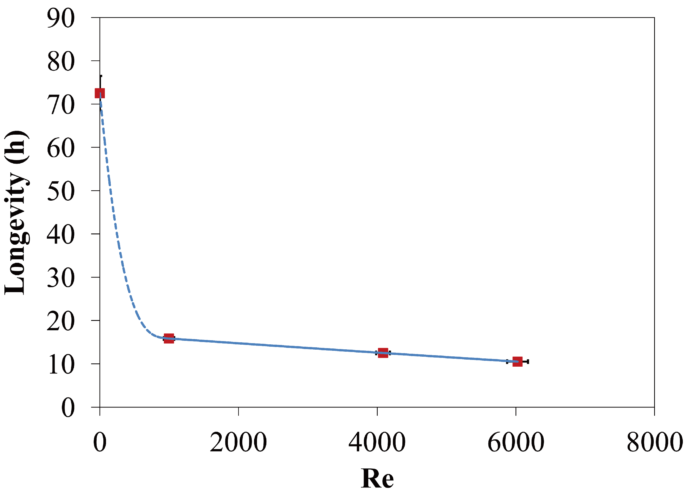
4.1.3. Longevity of Superhydrophobic Coatings

Even when the air–water interface on a superhydrophobic surface is mechanically stable, the surface is likely to lose its entrapped air content over time. This is especially the case when the surface is submerged. This effect is believed to be due to the dissolution of air in water, and is expected to accelerate when the hydrostatic pressure and water flowrate increased. The solubility of air in water increases with pressure and due to the forced convection of mass transfer.
Several studies implemented different optical techniques to measure how long superhydrophobic surfaces could entrap air underwater (surface longevity). For example, Bobji et al. [8] measured longevity of a superhydrophobic surface by measuring the number of shiny spots that indicate an interface between air and water. Similar studies were performed using a laser beam to investigate the effect of the surface structure on the longevity [9]. Moreover, Poetes et al. [11] used a different optical technique to investigate the effect of mild pressure on longevity of a superhydrophobic surface. Additionally, they mathematically interpreted the decay of longevity with pressure. Using optical measurements, Lei et al. [105] demonstrated that the wetting transition due to pressure could be either reversible (switching from nonwetted to wetted or vice versa) or irreversible (permanent wetting) depending on the value of the applied pressure. Rathgen and Mugele [106] developed an optical method to determine the contact angle and microscopic shape of the air–water interface under different hydrostatic pressure.
Samaha et al. [20] developed an optical technique to measure the longevity of submerged superhydrophobic coatings subjected to different environmental conditions. They used an optical spectroscopy system to quantify the intensity of reflected light in the visible range scattered from the surface (Figure 34). The time-dependent light reflection intensity was measured at both a single wavelength and integrated over a range of wavelengths. Note that it is important to be able to measure the hydrophobicity of a surface in situ because the traditional contact angle or rheometer measurements might not necessarily represent the environment in which a surface might operate in practice. This includes, but is not limited to a broad range of time-dependent hydrostatic pressures (i.e., depths), and different degrees of salinity and/or air saturation. It is also of particular importance to be able to test a surface hydrophobicity over time under moving or still water. The optical spectroscopy system proposed by Samaha et al., could be utilized as a noninvasive method to measure surface hydrophobicity under the above conditions.
Figure 34. (a) Schematic of optical spectroscopy system. (b) Photograph of custom pressure vessel. From Samaha et al. [20].
Polymers 06 01266 g034
Figure 35 shows the normalized reflected-light intensity as a function of time and wavelength for an electrospun fibrous coating submerged in water. The light intensity decreases with time at all wavelengths, which indicates a reduction in the volume of the entrapped air over time, and so the superhydrophobicity of the surface. Figure 36 shows the normalized average reflected light intensity (the integral of the light intensity over all wavelengths divided by the wavelength range). The results shown in this figure were obtained under atmospheric pressure. The figure shows that the average reflected light intensity decreases by about 27% after 166.5 h of continuous submersion in water.
Figure 35. Reduction in reflected light intensity with time for spun-fiber sample. Measurements are taken for entire visible-light spectrum. From Samaha et al. [20].
Polymers 06 01266 g035
Figure 36. Average reflected-light intensity reduction with time for spun-fiber sample. From Samaha et al. [20].
Polymers 06 01266 g036
For validation, Samaha et al. [20] compared the results obtained from the optical system with drag reduction data using a parallel plate rheometer. Figure 37 shows the measured drag reduction versus strain rate for the fibrous coating before and after the longevity test. The results indicate that the coating is still capable of reducing drag after 166.5 h of immersion in water under atmospheric pressure. The average drag reduction was decreased by about 31% with respect to that of the fresh specimen, which is close to the reduction in light intensity using the optical system.
Figure 37. Drag reduction versus strain rate. From Samaha et al. [20].
Polymers 06 01266 g037
For further validation, static contact angles and contact-angle hysteresis were measured for the same sample using a ramé-hart goniometer. The measurements, which followed the protocols suggested by Drelich [107], indicated that the results of the light-scattering technique correlate strongly with both contact-angle and drag-reduction measurements. The contact-angle hysteresis measurements further validated the light-scattering method. Low-contact-angle hysteresis was observed for the fresh superhydrophobic sample. However, more noticeable hysteresis was seen for aged specimens. These results were consistent with the observations of other studies [1,7]. In situ characterization of submerged hydrophobic surfaces using optical light scattering represents a useful tool for real-time estimation of hydrophobicity and drag reduction.
The optical technique was adapted to perform a systematic study to investigate the influence of different environments on longevity of superhydrophobic fibrous coatings. They studied the effect of hydrostatic pressure [76], water flow [108], and salinity of water [109]. Figure 38 shows an example of the longevity measurements versus pressure conducted for the fibrous coatings. The figure shows that as pressure increases, longevity exponentially decreases in a good agreement with another published theory [11], but at much higher pressure.
Figure 38. Effect of elevated pressure on longevity of superhydrophobic fibrous coating. Solid line is exponential fit of experimental data. From Samaha et al. [76].
Polymers 06 01266 g038
According to Poetes et al. [11], the gases in the trapped air (N2, O2, etc.) could be considered ideal gases whose fugacities f satisfy the following differential relation:
Polymers 06 01266 i005
where P is the hydrostatic pressure, v is the molar volume, R is the gas constant, c is the dissolved gas concentration, and T is the temperature. By integrating both sides between a hydrostatic pressure, P, and atmospheric pressure, P0, and substituting the equilibrium partial pressure P′ for the fugacities, one gets:
Polymers 06 01266 i006
or
Polymers 06 01266 i007
Equation (5) indicates an exponential increase of the partial vapor pressures of the gases in the trapped air with hydrostatic pressure, which leads to an exponential increase of air solubility in water and hence exponential decay of coating’s longevity (Figure 38). Additionally, the figure indicates that the terminal pressure for this particular coating could go up to 9.5 bar, which is two orders of magnitudes higher than those observed in other studies [8,11] for other coatings. Samaha et al. [76] interpreted that the scale of microroughness (the distances between the fibers) was about five microns at some locations and approached nanoscales at others, while the corresponding scales in the studies [8,11] were of the order of hundred microns. The significantly smaller scales of the fibrous coatings increase the sustainability of the air–water interface against pressure, indicating that such coatings could potentially be used for deep underwater applications. The results also indicated that the theory of Poetes et al. [11] was applicable for a much wider range of pressures. In a related theoretical study, Emami et al. [110] modeled the longevity of parallel grooves superhydrophobic surfaces subjected to different pressures. It was found that for grooves with higher width-to-depth ratios, the critical pressure was higher due to stronger resistance to deflection of the air–water interface from the air trapped in such grooves. However, grooves with higher width-to-depth ratios reached the Wenzel state faster because of their greater air–water interface areas.
Another environmental condition, water movement, was also studied [108]. Experiments were carried out to investigate the impact of flow on longevity of polystyrene fibrous coatings. The time-dependent hydrophobicity of a submerged coating in the pressure vessel was determined while exposing the coating to a rudimentary wall-jet flow. Figure 39 shows the period that the samples take for wetting transition (longevity) against jet-Reynolds number (Re). The figure demonstrates that as Re increases, longevity deteriorates. As water flows even with a relatively small Reynolds number, the flowrate strongly enhances the dissolution of the entrapped air in water where the mass-transfer free-convection regime turns into a forced convection one. The mass-transfer convection coefficients for both free and forced convection were determined.
Figure 39. Effect of water movement on longevity of superhydrophobic fibrous coating. Solid and broken lines are best fit of experimental data in forced, free and mixed convection regimes. From Samaha et al. [108].
Polymers 06 01266 g039
On the other hand, Barth et al. provided semi-analytical and numerical models to simulate the longevity of superhydrophobic flat surface comprised of spanwise microridges and subjected to both laminar [111] and turbulent [112] parallel flow. They solved the continuity, momentum, and mass transfer governing equations. The mass-transfer solution was achieved as a function of the gas fraction, Reynolds number, and Schmidt number. Longevity was estimated from a developed mass-transfer correlations.
The effect of water salinity on longevity was studied by Ochanda et al. [109]. The authors provided experimental study to observe the influence of salt (sodium chloride, NaCl) concentrations in aqueous solutions on hydrophobicity and longevity of fibrous coatings. The results indicated that both drag reduction and static contact angle decreased with increasing salt concentration. Moreover, measurements using the optical spectroscopy technique (Figure 34) were performed and showed that the coating longevity was lower for salt water in comparison to deionized water. The authors reasoned that Na+ and Cl ions are adsorbed on the polystyrene surface and the accumulation of positive and negative
charges with time leads to decrease in the hydrophobic force and hence reduces surface’s longevity.
The longevity of a submerged superhydrophobic surface depends primarily on the amount of time that air remains trapped within the surface microstructure. In other words, the degree of hydrophobicity and hence the beneficial effects are temporally diminished by the reduction of the amount of air. Keeping and/or restoring the air layer between the surface and water were undertaken by few studies. For example, Stephani and Goldstein [113] utilized the electrolysis process to continuously generate air bubbles between a solid surface and water, which lead to producing drag reduction even if the surface is not hydrophobic. Lee and Kim [114] used a similar process to rejuvenate dead microfabricated coatings, i.e., gas restoration for the wetted coatings to be converted back to be nonwetted.

4.2. Characterization of Omniphobic Surfaces

The techniques used to characterize superoleophobic surfaces are similar to those used for superhydrophobic ones. Yang et al. [28] experimentally investigated the effect of surface tension of low-surface energy liquids (e.g., dodecane, hexadecane, rapessed oil, and ethylene glycol) on oleophibicity of a fabricated coating. Figure 40 shows the variation of the apparent contact angle and sliding angle with the liquid surface tension for the coating. The surface was prepared by spraying a copper perfluorooctanoate suspension onto a substrate. Static contact angles were higher than 150 degrees even with a quite low-surface-tension liquid (Figure 40a). Also, sliding angles were relatively low for the same liquids (Figure 40b). The results indicated the strong repellent properties of the coating to those liquids.
Figure 40. (a) Apparent contact angles and (b) sliding angles as function of liquid surface tension for superoleophobic coating. Insets show shapes of corresponding liquid droplets. From Yang et al. [28].
Polymers 06 01266 g040
On the other hand, Jin et al. [27] demonstrated that a nanocellulose aerogel superoleophobic coating could produce drag reduction (measured by a rheometer). The drag reduction was obtained for a working fluid of silicone oil. Moreover, the stability of air–liquid interface under pressure was evaluated by measuring the buoyancy force supporting a loaded float surface. The meniscus stability was demonstrated for both paraffin oil and water.
Droplet mobility and behavior on lubricant-impregnated surfaces (such as SLIPS) were characterized by Smith et al. [115]. The substrate was comprised of microposts. The authors demonstrated twelve possible thermodynamic configurations of a droplet on the lubricated surface as shown in Figure 41. The droplet might pull up the lubricant and completely cloaked by it if Sow(a) = γwa − γwo − γoa > 0, where γ is the interfacial tension between the two phases designated by subscripts w (water), o (oil), and a (air), whereas Sow(a) < 0 implies otherwise. In the figure, r = 1 + 4ah/(a + b)2, which is the ratio of the total surface area to the projected area of the solid, a is post’s width = 10 µm, b is edge-to-edge spacing = 10 µm, h is post’s height = 10 µm, ϕ = a2/(a + b)2, which is the solid area fraction, θ is the static contact angle, θc = cos−1[(1 − ϕ)/(r − ϕ)], and the subscript s refers to the solid surface.
Figure 41. Possible thermodynamic states of water droplet placed on lubricant-impregnated surface. The top two schematics show whether or not the droplet gets cloaked by lubricant. For each case, there are six possible states depending on how the lubricant wets texture in presence of air (vertical axis) and water (horizontal axis). From Smith et al. [115].
Polymers 06 01266 g041
As described by Smith et al., the configurations possible outside the droplet are A1 (not impregnated, i.e., dry), A2 (impregnated with emergent features), and A3 (impregnated with submerged features, i.e., encapsulated). Meanwhile, underneath the droplet, the possible configurations are W1 (impaled), W2 (impregnated with emergent features), and W3 (impregnated with submerged features, i.e., encapsulated). The stable configuration is the one that has the lowest total interface energy to be thermodynamically satisfied.
Wong et al. [31] demonstrated that the lubricant serves as a self-healing coating for SLIPS that it quickly restores the liquid-repellent property after damaging the porous material by abrasion or impact. The surface favors to wet the lubricant by the capillary action, and spontaneously refills the physical voids as shown in Figure 42a,b. Enhancing the optical transparency in visible and/or near-infrared wavelengths was also demonstrated for such surfaces (Figure 42c–e). This could be achieved by matching refractive indices of substrate and lubricant materials. This is not easy to achieve through superhydrophobic surfaces because of the large difference in refractive index at the solid–air interface of these structured surfaces. Okada and Shiratori [116] fabricated highly transparent SLIPS using a facile nanoscale phase separation. This method could be utilized to prepare ultra-omniphobic glasses. Wong et al. [31] showed that SLIPS could repel ice, insects, and complex fluid such as blood and crude oil. In other publications, SLIPS was demonstrated for applications requiring anti-biofouling performance [117,118], antibacterial attainment [119], and repelling liquids at temperature higher than 100 °C [120].
Figure 42. Self-healing and optical transparency of Slippery Liquid-Infused Porous Surfaces (SLIPS). (a) Time-lapse images showing capability of SLIPS to self-heal from physical damage ~50 µm wide on timescale of order of 100 ms; (b) Time-lapse images showing restoration of liquid repellency of SLIPS after physical damage, as compared to typical hydrophobic flat surface (coated with DuPont Teflon AF amorphous fluoropolymers) on which oil remains pinned at the damage site. (c) Optical images showing enhanced optical transparency of epoxy-resin-based SLIPS (left) as compared to significant scattering in non-infused superhydrophobic nanostructured surface (right) in visible light range. Top panels show top views; bottom panels show schematic side views. (d) Optical transmission measurements for epoxy-resin-based SLIPS in the visible light range (400–750 nm). (e) Optical transmission measurements for Teflon-based SLIPS in the near-infrared range (800–2300 nm). From Wong et al. [31].
Polymers 06 01266 g042

5. Concluding Remarks

The present paper provided a broad review of recent research in hydrophobic and omniphobic coatings. Several design ideas have been inspired from nature. Biological mechanisms could be studied to engineer systems for modern industrial applications. Superhydrophobic surfaces were inspired by some biological creatures including lotus leaves, water striders, and wings of some butterflies. Currently, the lotus effect is employed to produce water-repellent paint and fabrics for self-cleaning, waterproofing, and anti-icing applications. Moreover, such surfaces were shown in several experimental, numerical, and analytical studies to reduce drag for both laminar and turbulent flows. This reinforces the optimistic view that these surfaces could be used for drag reduction purposes, especially in marine environments. For submerged superhydrophobic surfaces, drag reduction and slip flow take place at the interface between the entrapped air and water. The performance of the surface is characterized by slip length, which is strongly affected by gas void fraction for both laminar and turbulent flows.
Other examples of slippery surfaces, superoleophobic coatings, were developed to repel different liquids with much lower surface tension than that of water. Such coatings were considered omniphobic because they could repel different liquids. The surfaces exploit the same phenomenon of lotus effect, i.e., entrap air in micro/nanopores. However, to engineer a superoleophobic coating, the local curvature of the surface microsrtucture, so-called re-entrant geometry, should be considered in addition to combination of surface roughness and well matched low surface energy. The surface characteristics affect the apparent contact angle, hysteresis, stability of the air–liquid interface (plastron) under loads, and drag reduction. Such coatings could be utilized in a wide range of applications including resisting biofouling and self-cleaning in water polluted oil slicks. A recent example of omniphobic coatings is the slippery liquid-infused porous surfaces (SLIPS). Such a coating was inspired by Nepenthes pitcher plants. SLIPS were engineered to entrap a low-surface energy intermediary infused liquid (lubricant) in a fluorinated microstructural roughness. The lubricant is utilized as a repellent surface for different kind of complex liquids. SLIPS were engineered similarly to superhydrophobic surfaces utilizing microfabrications of ordered or disordered roughness. However, the well-matched surface energies of the lubricant and the solid rough surface is very important. Such surfaces were demonstrated to achieve significantly low contact-angle hystereses indicating slip of the repelled liquid. Furthermore, the surfaces were experimentally manifested to possess some advantages such as self-healing after damage, working under high pressure and temperature, repelling insects and ice in addition to several complex fluids, anti-fouling, antibacterial performance, and enhancing optical transparency.
Slippery surfaces could be used as a passive control strategy to reduce drag on submerged vehicles. However, there are still significant issues that need to be resolved in order for the mass production of such coatings to be feasible. First, the microstructure of the coating should be strong enough to sustain the developed shear stress without erosion especially for turbulent flows. Second, the coating should retain its slipping property for an acceptable timeframe (reasonable longevity) by holding its lubricant (gas or liquid) locked in place. Third, the coating should be durable enough to sustain environmental conditions such as water salinity, depth, circulation, biofouling, etc. Few experiments demonstrated that these environments have an impact to reduce the surface longevity. Finally, the fabrication processes should be extended from laboratory scale to large industrial scale applications. Several studies presented different methods to produce cost-effective coatings, but the best coating for drag-reduction purposes is yet to be developed. All of these issues require further research before slippery coatings could be utilized for field applications.

Acknowledgments

This research is sponsored by the Defense Advanced Research Projects Agency (DARPA), contract numbers W91CRB-10-1-0003 and W911QX-12-1-0001, technical sponsor Captain ChristopherWarren, U.S. Navy. The content of this paper does not necessarily reflect the position or the policy of the Government, and no official endorsement should be inferred.

Author Contributions

Both authors equally contributed to collect, treat, write, and discuss the physics and results presented in the manuscript.

Conflicts of Interest

The authors declare no conflicts of interest.

References

  1. Bico, J.; Marzolin, C.; Quéré, D. Pearl drops. Europhys. Lett. 1999, 47, 220–226. [Google Scholar] [CrossRef]
  2. Quéré, D. Surface chemistry: Fakir droplets. Nat. Mater. 2002, 1, 14–15. [Google Scholar] [CrossRef]
  3. Feng, L.; Li, S.; Li, Y.; Li, H.; Zhang, L.; Zhai, J.; Song, Y.; Liu, B.; Jiang, L.; Zhu, D. Super-hydrophobic surfaces: From natural to artificial. Adv. Mater. 2002, 14, 1857–1860. [Google Scholar] [CrossRef]
  4. Callies, M.; Chen, Y.; Marty, F.; Pépin, A.; Quéré, D. Microfabricated textured surfaces for super-hydrophobicity investigations. Microelectron. Eng. 2005, 78–79, 100–105. [Google Scholar] [CrossRef]
  5. Davies, J.; Maynes, D.; Webb, B.W.; Woolford, B. Laminar flow in a microchannel with superhydrophobic walls exhibiting transverse ribs. Phys. Fluids 2006, 18. [Google Scholar] [CrossRef]
  6. Lee, C.; Choi, C.-H.; Kim, C.-J. Structured surfaces for giant liquid slip. Phys. Rev. Lett. 2008, 101. [Google Scholar] [CrossRef]
  7. Quéré, D. Wetting and roughness. Annu. Rev. Mater. Res. 2008, 38, 71–99. [Google Scholar] [CrossRef]
  8. Bobji, M.S.; Kumar, S.V.; Asthana, A.; Govardhan, R.N. Underwater sustainability of the “Cassie” state of wetting. Langmuir 2009, 25, 12120–12126. [Google Scholar] [CrossRef]
  9. Sakai, M.; Yanagisawa, T.; Nakajima, A.; Kameshima, Y.; Okada, K. Effect of surface structure on the sustainability of an air Layer on superhydrophobic coatings in a water–ethanol mixture. Langmuir 2009, 25, 13–16. [Google Scholar] [CrossRef]
  10. Rothstein, J.P. Slip on superhydrophobic surfaces. Annu. Rev. Fluid Mech. 2010, 42, 89–109. [Google Scholar] [CrossRef]
  11. Poetes, R.; Holtzmann, K.; Franze, K.; Steiner, U. Metastable underwater superhydrophobicity. Phys. Rev. Lett. 2010, 105. [Google Scholar] [CrossRef]
  12. Shirtcliffe, N.J.; McHale, G.; Atherton, S.; Newton, M.I. An introduction to superhydrophobicity. Adv. Colloid Interface Sci. 2010, 161, 124–138. [Google Scholar] [CrossRef]
  13. Samaha, M.A.; Tafreshi, H.V.; Gad-el-Hak, M. Superhydrophobic surfaces: From the lotus leaf to the submarine. C. R. Mec. 2012, 340, 18–34. [Google Scholar] [CrossRef]
  14. Neinhuis, C.; Barthlott, W. Characterization and distribution of water-repellent, self-cleaning plant surfaces. Ann. Bot. 1997, 79, 667–677. [Google Scholar] [CrossRef]
  15. Gao, X.; Jiang, L. Water-repellent legs of water striders. Nature 2004, 432, 36. [Google Scholar] [CrossRef]
  16. Lafuma, A.; Quéré, D. Superhydrophobic states. Nat. Mater. 2003, 2, 457–460. [Google Scholar] [CrossRef]
  17. Wenzel, R.N. Resistance of solid surfaces to wetting by water. Ind. Eng. Chem. 1936, 28, 988–994. [Google Scholar] [CrossRef]
  18. Cassie, A.B.D.; Baxter, S. Wettability of porous surfaces. Trans. Faraday Soc. 1944, 40, 546–551. [Google Scholar] [CrossRef]
  19. Navier, C.L.M.H. Memoire sur les lois du mouvement des fluides. Mem. Acad. R. Sci. Inst. France 1823, 6, 389–440. [Google Scholar]
  20. Samaha, M.A.; Ochanda, F.O.; Tafreshi, H.V.; Tepper, G.C.; Gad-el-Hak, M. In Situ, non-invasive characterization of superhydrophobic coatings. Rev. Sci. Instrum. 2011, 82, 045109. [Google Scholar]
  21. Pennisi, E. Water’s tough skin. Science 2014, 343, 1194–1197. [Google Scholar] [CrossRef]
  22. Tuteja, A.; Choi, W.; Ma, M.; Mabry, J.M.; Mazzella, S.A.; Rutledge, G.C.; McKinley, G.H.; Cohen, R.E. Designing superoleophobic surfaces. Science 2007, 318, 1618–1622. [Google Scholar] [CrossRef]
  23. Tuteja, A.; Choi, W.; McKinley, G.H.; Cohen, R.E.; Rubner, M.F. Design parameters for superhydrophobicity and superoleophobicity. MRS Bull. 2008, 33, 752–758. [Google Scholar] [CrossRef]
  24. Joly, L.; Biben, T. Wetting and friction on superoleophobic surfaces. Soft Matter 2009, 5, 2549–2557. [Google Scholar]
  25. Leng, B.; Shao, Z.; de With, G.; Ming, W. Superoleophobic cotton textiles. Langmuir 2009, 25, 2456–2460. [Google Scholar]
  26. Ramos, S.M.M.; Benyagoub, A.; Canut, B.; Jamois, C. Superoleophobic behavior induced by nanofeatures on oleophilic surfaces. Langmuir 2010, 26, 5141–5146. [Google Scholar]
  27. Jin, H.; Kettunen, M.; Laiho, A; Pynnönen, J.; Paltakari, J.; Marmur, A.; Ikkala, O.; Ras, R.H.A. Superhydrophobic and superoleophobic nanocellulose aerogel membranes as bioinspired cargo carriers on water and oil. Langmuir 2011, 27, 1930–1934. [Google Scholar]
  28. Yang, J.; Zhang, Z.; Men, X.; Xu, X.; Zhu, X. A simple approach to fabricate superoleophobic coatings. New J. Chem. 2011, 35, 576–580. [Google Scholar] [CrossRef]
  29. Zhao, H.; Law, K.-Y. Directional self-cleaning superoleophobic surface. Langmuir 2012, 28, 11812–11818. [Google Scholar] [CrossRef]
  30. Jin, H.; Tian, X.; Ikkala, O.; Ras, R.H.A. Preservation of superhydrophobic and superoleophobic properties upon wear damage. ACS Appl. Mater. Interfaces 2013, 5, 485–488. [Google Scholar]
  31. Wong, T.-S.; Kang, S.H.; Tang, S.K.Y.; Smythe, E.J.; Hatton, B.D.; Grinthal, A.; Aizenberg, J. Bioinspired self-repairing slippery surfaces with pressure-stable omniphobicity. Nature 2011, 477, 443–447. [Google Scholar] [CrossRef]
  32. Cheng, Y.T.; Rodak, D.E.; Hayden, C.A. Effects of micro- and nano-structures on the self-cleaning behaviour of lotus leaves. Nanotechnology 2006, 17, 1359–1362. [Google Scholar] [CrossRef]
  33. Koch, K.; Bhushan, B.; Jung, Y.C.; Barthlott, W. Fabrication of artificial Lotus leaves and significance of hierarchical structure for superhydrophobicity and low adhesion. Soft Matter 2006, 5, 1386–1393. [Google Scholar]
  34. WordPress. Available online: http://biodsign.files.wordpress.com/2008/08/lotusan.jpg (accessed on 5 May 2011).
  35. Flickr. Available online: http://www.flickr.com/photos/leonefabre/3922996122/ (accessed on 5 May 2011).
  36. Atomic World. Available online: http://www.hk-phy.org/atomic_world/lotus/lotus01_e.html (accessed on 5 May 2011).
  37. Thenakedscientists. Available online: http://www.thenakedscientists.com/HTML/articles/article/biomimetics borrowingfrombiology/ (accessed on 5 May 2011).
  38. Cheng, Y.T.; Rodak, D.E. Is the lotus leaf superhydrophobic? Appl. Phys. Lett. 2005, 86. [Google Scholar] [CrossRef]
  39. Wikimedia Commons. Available online: http://commons.wikimedia.org/wiki/File:Water-strider-1.jpg (accessed on 11 May 2011).
  40. Feng, X.-Q.; Gao, X.; Wu, Z.; Jiang, L.; Zheng, Q.-S. Superior water repellency of water strider legs with hierarchical structures: Experiments and analysis. Langmuir 2007, 23, 4892–4896. [Google Scholar] [CrossRef]
  41. Bush, J.W.M.; Hu, D.L. Walking on water: Biolocomotion at the interface. Annu. Rev. Fluid Mech. 2006, 38, 339–369. [Google Scholar] [CrossRef]
  42. Hu, D.L.; Chan, B.; Bush, J.W.M. The hydrodynamics of water strider locomotion. Nature 2003, 424, 663–666. [Google Scholar] [CrossRef]
  43. Hu, D.L.; Prakash, M.; Chan, B.; Bush, J.W.M. Water-walking devices. Exp. Fluids 2007, 43, 769–778. [Google Scholar] [CrossRef]
  44. Stonedahl, G.M.; Lattin, J.D. The Gerridae or Water striders of oregon and Washington (Hemiptera:Heteroptera). In Technical Bulletin 144; Oregon State University: Corvallis, OR, USA, 1982; pp. 1–36. [Google Scholar]
  45. Flynn, M.R.; Bush, J.W.M. Underwater breathing: The mechanics of plastron respiration. J. Fluid Mech. 2008, 608, 275–296. [Google Scholar]
  46. Zheng, Y.; Gao, X.; Jiang, L. Directional adhesion of superhydrophobic butterfly wings. Soft Matter 2007, 3, 178–182. [Google Scholar]
  47. Xia, F.; Jiang, L. Bio-inspired, smart, multiscale interfacial materials. Adv. Mater. 2008, 20, 2842–2858. [Google Scholar] [CrossRef]
  48. Nitrogenseekers. Available online: http://nitrogenseekers.wordpress.com/page/36/ (accessed on 20 November 2013).
  49. Bauer, U.; Federle, W. The insect-trapping rim of Nepenthes pitchers surface structure and function. Plant Signal. Behav. 2009, 4, 1019–1023. [Google Scholar] [CrossRef]
  50. Bohn, H.F.; Federle, W. Insect aquaplaning: Nepenthes pitcher plants capture prey with the peristome, a fully wettable water-lubricated anisotropic surface. Proc. Natl. Acad. Sci. USA 2004, 101, 14138–14143. [Google Scholar] [CrossRef]
  51. Barthlott, W.; Porembski, S.; Seine, R.; Theisen, I. The Curious World of Carnivorous Plants; Timber Press: Portland, ON, USA, 2007. [Google Scholar]
  52. Maynes, D.; Jeffs, K.; Woolford, B.; Webb, B.W. Laminar flow in a microchannel with hydrophobic surface patterned microribs oriented parallel to the flow direction. Phys. Fluids 2007, 19. [Google Scholar] [CrossRef]
  53. Bico, J.; Thiele, U.; Quéré, D. Wetting of textured surfaces. Colloids Surf. A 2002, 206, 41–46. [Google Scholar] [CrossRef]
  54. Henoch, C.; Krupenkin, T.N.; Kolodner, P.; Taylor, J.A.; Hodes, M.S.; Lyons, A.M.; Peguero, C.; Breuer, K. Turbulent drag reduction using superhydrophobic surfaces. In Proceedings of 3rd AIAA Flow Control Conference, San Francisco, CA, USA, 5–8 June 2006.
  55. Choi, C.-H.; Kim, C.-J. Large slip of aqueous liquid flow over a nanoengineered superhydrophobic surface. Phys. Rev. Lett. 2006, 96. [Google Scholar] [CrossRef]
  56. Lee, C.; Kim, C-J. Maximizing the giant slip on superhydrophobic microstructures by nanostructuring their sidewalls. Langmuir 2009, 25, 12812–12818. [Google Scholar] [CrossRef]
  57. Jung, Y.C.; Bhushan, B. Mechanically durable carbon nanotube–composite hierarchical structures with superhydrophobicity, self-cleaning, and low-drag. ACS Nano 2009, 3, 4155–4163. [Google Scholar] [CrossRef]
  58. Zhu, X.; Zhang, Z.; Men, X.; Yang, J.; Wang, K.; Xu, X.; Zhou, X.; Xue, Q. Robust superhydrophobic surfaces with mechanical durability and easy repairability. J. Mater. Chem. 2011, 21, 15793–15797. [Google Scholar]
  59. Emami, B.; Bucher, T.M.; Tafreshi, H.V.; Pestov, D.; Gad-el-Hak, M.; Tepper, G.C. Simulation of meniscus stability in superhydrophobic granular surfaces under hydrostatic pressures. Colloids Surf. A 2011, 385, 95–103. [Google Scholar]
  60. Yang, H.; Deng, Y. Preparation and physical properties of superhydrophobic papers. J. Colloid Interface Sci. 2008, 325, 588–593. [Google Scholar] [CrossRef]
  61. Bhagat, S.D.; Kim, Y.-H.; Suh, K.-H.; Ahn, Y.-S.; Yeo, J.-G.; Han, J.-H. Super hydrophobic silica aerogel powders with simultaneous surface modification, solvent exchange and sodium ion removal from hydrogels. Microporous Mesoporous Mater. 2008, 112, 504–509. [Google Scholar] [CrossRef]
  62. Samaha, M.A.; Tafreshi, H.V.; Gad-el-Hak, M. Effects of hydrostatic pressure on the drag reduction of submerged aerogel-particle coatings. Colloids Surf. A 2012, 399, 62–70. [Google Scholar]
  63. Ma, M.; Mao, Y.; Gupta, M.; Gleason, K.K.; Rutledge, G.C. Superhydrophobic fabrics produced by electrospinning and chemical vapor deposition. Macromolecules 2005, 38, 9742–9748. [Google Scholar] [CrossRef]
  64. Singh, A.; Steely, L.; Allcock, H.R. Poly[bis(2,2,2-trifluoroethoxy)phosphazene] superhydrophobic nanofibers. Langmuir 2005, 21, 11604–11607. [Google Scholar] [CrossRef]
  65. Zhu, M.; Zuo, W.; Yu, H.; Yang, W.; Chen, Y. Superhydrophobic surface directly created by electrospinning based on hydrophilic material. J. Mater. Sci. 2006, 41, 3793–3797. [Google Scholar]
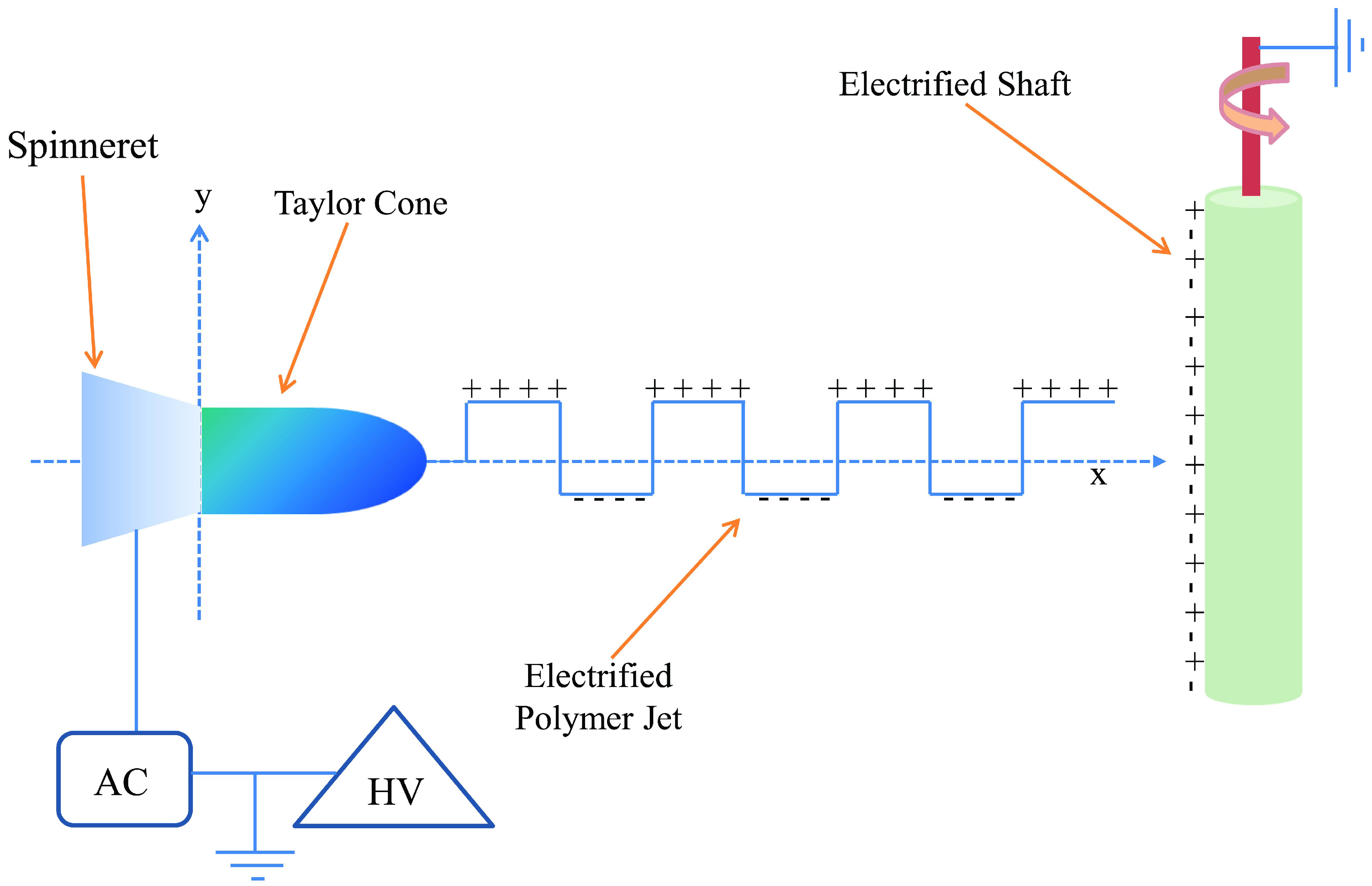
  66. Ochanda, F.O.; Samaha, M.A.; Tafreshi, H.V.; Tepper, G.C.; Gad-el-Hak, M. Fabrication of superhydrophobic fiber coatings by DC-biased AC-electrospinning. J. Appl. Polym. Sci. 2012, 123, 1112–1119. [Google Scholar] [CrossRef]
  67. Sarkar, S.; Deevi, S.; Tepper, G. Biased AC electrospinning of aligned polymer nanofibers. Macromol. Rapid Commun. 2007, 28, 1034–1039. [Google Scholar] [CrossRef]
  68. Wang, X.; Ding, B.; Yu, J.; Wang, M. Engineering biomimetic superhydrophobic surfaces of electrospun nanomaterials. Nano Today 2011, 6, 510–530. [Google Scholar] [CrossRef]
  69. Lin, J.; Wang, X.; Ding, B.; Yu, J.; Sun, G.; Wang, M. Biomimicry via electrospinning. Crit. Rev. Solid State Mater. Sci. 2012, 37, 94–114. [Google Scholar] [CrossRef]
  70. Laird, E.D.; Bose, R.K.; Qi, H.; Lau, K.K.S.; Li, C.Y. Electric field-induced, reversible lotus-to-rose transition in nanohybrid shish kebab paper with hierarchical roughness. ACS Appl. Mater. Interfaces 2013, 5, 12089–12098. [Google Scholar]
  71. Srinivasan, S.; Chhatre, S.S.; Mabry, J.M.; Cohen, R.E.; McKinley, G.H. Solution spraying of poly(methyl methacrylate) blends to fabricate microtextured, superoleophobic surfaces. Polymer 2011, 52, 3209–3218. [Google Scholar] [CrossRef]
  72. Srinivasan, S.; Choi, W.; Park, K.-C.; Chhatre, S.S.; Cohen, R.E.; McKinley, G.H. Drag reduction for viscous laminar flow on spray-coated non-wetting surfaces. Soft Matter 2013, 9, 5691–5702. [Google Scholar]
  73. Huang, X.; Chrisman, J.D.; Zacharia, N.S. Omniphobic slippery coatings based on lubricant-infused porous polyelectrolyte multilayers. ACS Macro Lett. 2013, 2, 826–829. [Google Scholar] [CrossRef]
  74. Shillingford, C.; MacCallum, N.; Wong, T-S.; Kim, P.; Aizenberg, J. Fabrics coated with lubricated nanostructures display robust omniphobicity. Nanotechnology 2014, 25. [Google Scholar] [CrossRef]
  75. Gad-el-Hak, M. Flow Control: Passive, Active, and Reactive Flow Management; Cambridge University Press: London, UK, 2000. [Google Scholar]
  76. Samaha, M.A.; Tafreshi, H.V.; Gad-el-Hak, M. Sustainability of superhydrophobicity under pressure. Phys. Fluids 2012, 24. [Google Scholar] [CrossRef]
  77. Gad-el-Hak, M. The fluid mechanics of microdevices—The freeman scholar lecture. J. Fluids Eng. 1999, 121, 5–33. [Google Scholar] [CrossRef]
  78. Lauga, E.; Brenner, M.P.; Stone, H.A. Microfluidics: The no-slip boundary condition. In Handbook of Experimental Fluid Dynamics; Tropea, C., Yarin, A., Foss, J., Eds.; Springer: New York, NY, USA, 2007; pp. 1219–1240. [Google Scholar]
  79. Samaha, M.A.; Tafreshi, H.V.; Gad-el-Hak, M. Modeling drag reduction and meniscus stability of superhydrophobic surfaces comprised of random roughness. Phys. Fluids 2011, 23. [Google Scholar] [CrossRef]
  80. Lauga, E.; Stone, H.A. Effective slip in pressure-driven Stokes flow. J. Fluid Mech. 2003, 489, 55–77. [Google Scholar] [CrossRef]
  81. Ou, J.; Perot, J.B.; Rothstein, J.P. Laminar drag reduction in microchannels using ultrahydrophobic surfaces. Phys. Fluids 2004, 16, 4635–4643. [Google Scholar] [CrossRef]
  82. Ou, J.; Rothstein, J.P. Direct velocity measurements of the flow past drag-reducing ultrahydrophobic surfaces. Phys. Fluids 2005, 17. [Google Scholar] [CrossRef]
  83. Ybert, C.; Barentin, C.; Cécile, C.-B.; Jospeh, P.; Bocquet, L. Achieving large slip with superhydrophobic surfaces: Scaling laws for generic geometries. Phys. Fluids 2007, 19. [Google Scholar] [CrossRef]
  84. Cheng, Y.P.; Teo, C.J.; Khoo, B.C. Microchannel flow with superhydrophobic surfaces: Effects of Reynolds number and pattern width to channel height ratio. Phys. Fluids 2009, 21. [Google Scholar] [CrossRef]
  85. Daniello, R.; Waterhouse, N.E.; Rothstein, J.P. Drag reduction in turbulent flows over superhydrophobic surfaces. Phys. Fluids 2009, 21. [Google Scholar] [CrossRef]
  86. Martell, M.; Perot, J.B.; Rothstein, J.P. Direct numerical simulations of turbulent flows over superhydrophobic surfaces. J. Fluid Mech. 2009, 620, 31–41. [Google Scholar]
  87. Davis, A.M.J.; Lauga, E. The friction of a mesh-like super-hydrophobic surface. Phys. Fluids 2009, 21. [Google Scholar] [CrossRef]
  88. Woolford, B.; Prince, J.; Maynes, D.; Webb, B.W. Particle image velocimetry characterization of turbulent channel flow with rib patterned superhydrophobic walls. Phys. Fluids 2009, 21. [Google Scholar] [CrossRef]
  89. Patankar, N.A. Transition between superhydrophobic states on rough surfaces. Langmuir 2004, 20, 7097–7102. [Google Scholar] [CrossRef]
  90. Barbieri, L.; Wagner, E.; Hoffmann, P. Water wetting transition parameters of perfluorinated substrates with periodically distributed flat-top microscale obstacles. Langmuir 2007, 23, 1723–1734. [Google Scholar] [CrossRef]
  91. Extrand, C.W. Criteria for ultralyophobic surfaces. Langmuir 2004, 20, 5013–5018. [Google Scholar] [CrossRef]
  92. Extrand, C.W. Designing for optimum liquid repellency. Langmuir 2006, 22, 1711–1714. [Google Scholar]
  93. Zheng, Q.S.; Yu, Y.; Zhao, Z.H. Effects of hydraulic pressure on the stability and transition of wetting modes of superhydrophobic surfaces. Langmuir 2005, 21, 12207–12212. [Google Scholar] [CrossRef]
  94. Okabe, A.; Boots, B.; Sugihara, K.; Chiu, S.N.; Kendall, D.G. Spatial Tessellations: Concepts andApplications of Voronoi Diagrams, 2nd ed.; John Wiley & Sons Ltd: Chichester, England, 2000. [Google Scholar]
  95. Emami, B.; Tafreshi, H.V.; Gad-el-Hak, M.; Tepper, G.C. Predicting shape and stability of air–water interface on superhydrophobic surfaces with randomly distributed, dissimilar posts. Appl. Phys. Lett. 2011, 98, 203106:1–203106:3. [Google Scholar]
  96. Bucher, T.M.; Emami, B.; Tafreshi, H.V.; Gad-el-Hak, M.; Tepper, G.C. Modeling resistance of nanofibrous superhydrophobic coatings to hydrostatic pressures: The role of microstructure. Phys. Fluids 2012, 24. [Google Scholar] [CrossRef]
  97. Kang, Q.; Wang, M.; Mukherjee, P.P.; Lichtner, P.C. Mesoscopic modeling of multiphysicochemical transport phenomena in porous media. Adv. Mech. Eng. 2010, 2010, 142879:1–142879:11. [Google Scholar]
  98. Mukherjee, P.P.; Kang, Q.; Wang, C-Y. Pore-scale modeling of two-phase transport in polymer electrolyte fuel cells—Progress and perspective. Energy Environ. Sci. 2011, 4, 346–369. [Google Scholar] [CrossRef]
  99. Emami, B.; Tafreshi, H.V.; Gad-el-Hak, M.; Tepper, G.C. Predicting shape and stability of air–water interface on superhydrophobic surfaces comprised of pores with arbitrary shapes and depths. Appl. Phys. Lett. 2012, 100, 013104:1–013104:4. [Google Scholar]
  100. Emami, B.; Tafreshi, H.V.; Gad-el-Hak, M.; Tepper, G.C. Effect of fiber orientation on shape and stability of air–water interface on submerged superhydrophobic electrospun thin coatings. J. Appl. Phys. 2012, 111. [Google Scholar] [CrossRef]
  101. Extrand, C.W. Repellency of the Lotus Leaf: Resistance to Water Intrusion under Hydrostatic Pressure. Langmuir 2011, 27, 6920–6925. [Google Scholar] [CrossRef]
  102. Sheng, X.; Zhang, J. Air layer on superhydrophobic surface underwater. Colloids Surf. A 2011, 377, 374–378. [Google Scholar] [CrossRef]
  103. Otsu, N. A threshold selection method from gray-level histograms. IEEE Trans. Syst. Man Cybern. 1979, 9, 62–66. [Google Scholar] [CrossRef]
  104. Samaha, M.A.; Tafreshi, H.V.; Gad-el-Hak, M. Novel method to characterize superhydrophobic coatings. J. Colloid Interface Sci. 2013, 395, 315–321. [Google Scholar] [CrossRef]
  105. Lei, L.; Li, H.; Shi, J.; Chen, Y. Diffraction patterns of a water-submerged superhydrophobic grating under pressure. Langmuir 2010, 26, 3666–3669. [Google Scholar] [CrossRef]
  106. Rathgen, H.; Mugele, F. Microscopic shape and contact angle measurement at a superhydrophobic surface. Faraday Discuss. 2010, 146, 49–56. [Google Scholar] [CrossRef]
  107. Drelich, J. Guidelines to measurements of reproducible contact angles using a sessile-drop technique. Surface Innovations 2013, 1, 248–254. [Google Scholar] [CrossRef]
  108. Samaha, M.A.; Tafreshi, H.V.; Gad-el-Hak, M. Influence of flow on longevity of superhydrophobic coatings. Langmuir 2012, 28, 9759–9766. [Google Scholar] [CrossRef]
  109. Ochanda, F.O.; Samaha, M.A.; Tafreshi, H.V.; Tepper, G.C.; Gad-el-Hak, M. Salinity effects on the degree of hydrophobicity and longevity for superhydrophobic fibrous coatings. J. Appl. Polym. Sci. 2012, 124, 5021–5026. [Google Scholar]
  110. Emami, B.; Hemeda, A.A.; Amrei, M.M.; Luzar, A.; Gad-el-Hak, M.; Tafreshi, H.V. Predicting longevity of submerged superhydrophobic surfaces with parallel grooves. Phys. Fluids 2013, 25. [Google Scholar] [CrossRef]
  111. Barth, C.A.; Samaha, M.A.; Tafreshi, H.V.; Gad-el-Hak, M. Convective mass transfer from submerged superhydrophobic surfaces. Int. J. Flow Contr. 2013, 5, 79–88. [Google Scholar] [CrossRef]
  112. Barth, C.A.; Samaha, M.A.; Tafreshi, H.V.; Gad-el-Hak, M. Convective mass transfer from submerged superhydrophobic surfaces: Turbulent flow. Int. J. Flow Contr. 2013, 5, 143–152. [Google Scholar] [CrossRef]
  113. Stephani, K.A.; Goldstein, D.B. An Examination of trapped bubbles for viscous drag reduction on submerged surfaces. J. Fluids Eng. 2010, 132. [Google Scholar] [CrossRef]
  114. Lee, C.; Kim, C.-J. Underwater restoration and retention of gases on superhydrophobic surfaces for drag reduction. Phys. Rev. Lett. 2011, 106. [Google Scholar] [CrossRef]
  115. Smith, J.D.; Dhiman, R.; Anand, S.; Reza-Garduno, E.; Cohen, R.E.; McKinley, G.H.; Varanasi, K.K. Droplet mobility on lubricant-impregnated surfaces. Soft Matter 2013, 9, 1772–1780. [Google Scholar]
  116. Okada, I.; Shiratori, S. High-transparency, self-standable Gel-SLIPS fabricated by a facile nanoscale phase separation. ACS Appl. Mater. Interfaces 2014, 6, 1502–1508. [Google Scholar] [CrossRef]
  117. Epstein, A.K.; Wong, T.-S.; Belisleb, R.A.; Boggsa, E.M.; Aizenberg, J. Liquid-infused structured surfaces with exceptional anti-biofouling performance. Proc. Natl. Acad. Sci. USA 2012, 109, 13182–13187. [Google Scholar]
  118. Xiao, L.; Li, J.; Mieszkin, S.; Fino, A.D.; Clare, A.S.; Callow, M.E.; Callow, J.A.; Grunze, M.; Rosenhahn, A.; Levkin, P.A. Slippery liquid-infused porous surfaces showing marine antibiofouling properties. ACS Appl. Mater. Interfaces 2013, 5, 10074–10080. [Google Scholar]
  119. Li, J.; Kleintschek, T.; Rieder, A.; Cheng, Y.; Baumbach, T.; Obst, U.; Schwartz, T.; Levkin, P.A. Hydrophobic liquid-infused porous polymer surfaces for antibacterial applications. ACS Appl. Mater. Interfaces 2013, 5, 6704–6711. [Google Scholar] [CrossRef]
  120. Daniel, D.; Mankin, M.N.; Belisleb, R.A.; Wong, T.-S.; Aizenberg, J. Lubricant-infused micro/nano-structured surfaces with tunable dynamic omniphobicity at high temperatures. Appl. Phys. Lett. 2013, 102. [Google Scholar] [CrossRef]

