
Parametric Study of Geometry and Process Parameter Influences on Additively Manufactured Piezoresistive Sensors Under Cyclic Loading


Abstract
1. Introduction
2. Materials and Methods
2.1. Sensor Design and Additive Manufacturing
2.2. Measurement
2.3. Analyzed Properties
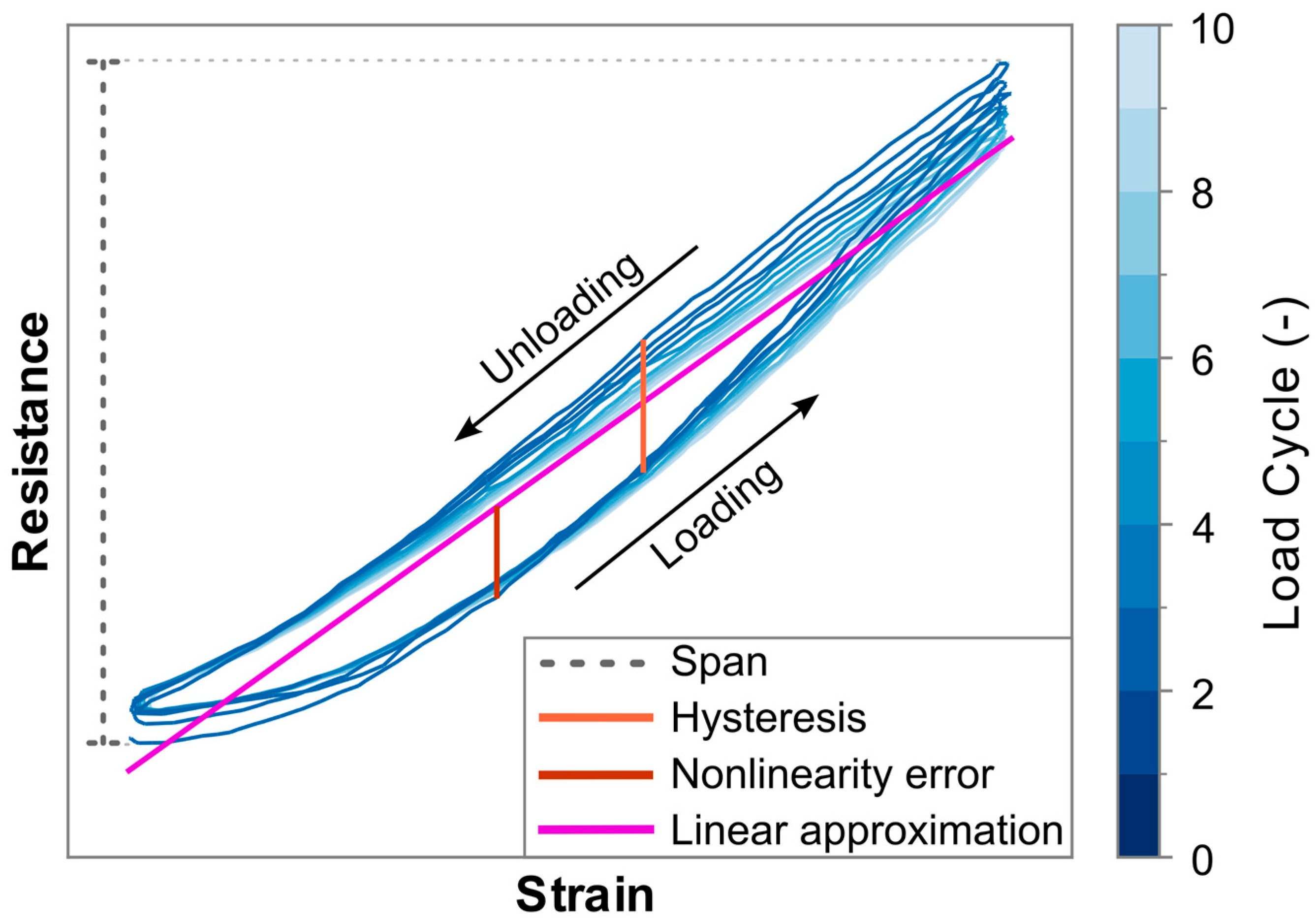
- Nonlinearity error: The absolute maximum difference that occurs between a sensor’s resistance in response to strain, and a best fit straight line (BFSL) type of linear approximation of that signal. Both the BFSL and the nonlinearity error are depicted in Figure 3.
- Hysteresis error: The maximum difference between the upwards and downwards slopes of the resistance at any given strain level within a cycle, as shown in Figure 3.
- Drift over multiple load cycles: Analyzed using the approach as demonstrated in the work of Scholle et al. [66], which utilizes the slope of a linear approximation of the resistance over time signal, as illustrated in Figure 4. Because the load case for the experiments in the current work forms a symmetrical signal, with this approach a theoretical perfect piezoresistive material, without any drift, would exhibit a linear approximation with zero slope. A positive or a negative slope value indicates that the sensor response exhibits an increasing or decreasing trend in resistance under repeated loading, respectively. The values used in this work are the average increase or decrease per load cycle as a percentage of the span for that particular sensor. The approach of Scholle et al. is selected over similar ones used to characterize additively manufactured sensors by Georgopoulou et al. [50] or Gooding et al. [29], because the former considers only changes in the maximum values, disregarding potential drift in the minimum resistance values, while the latter analyzes the drift only for the first two cycles.
3. Results and Discussion
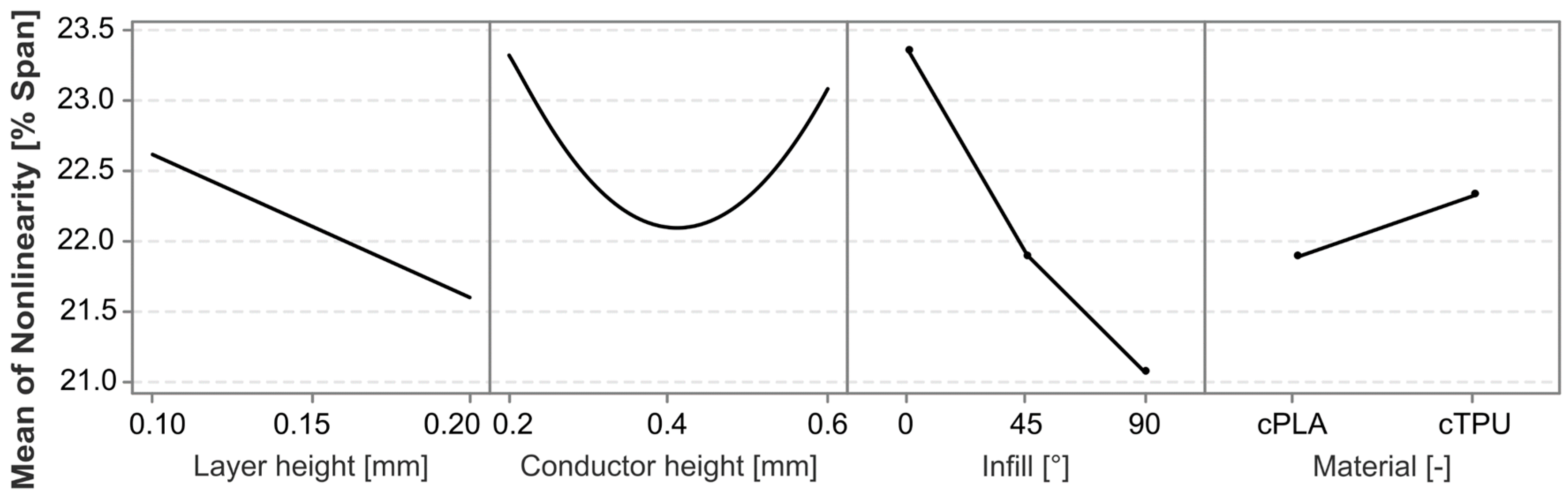
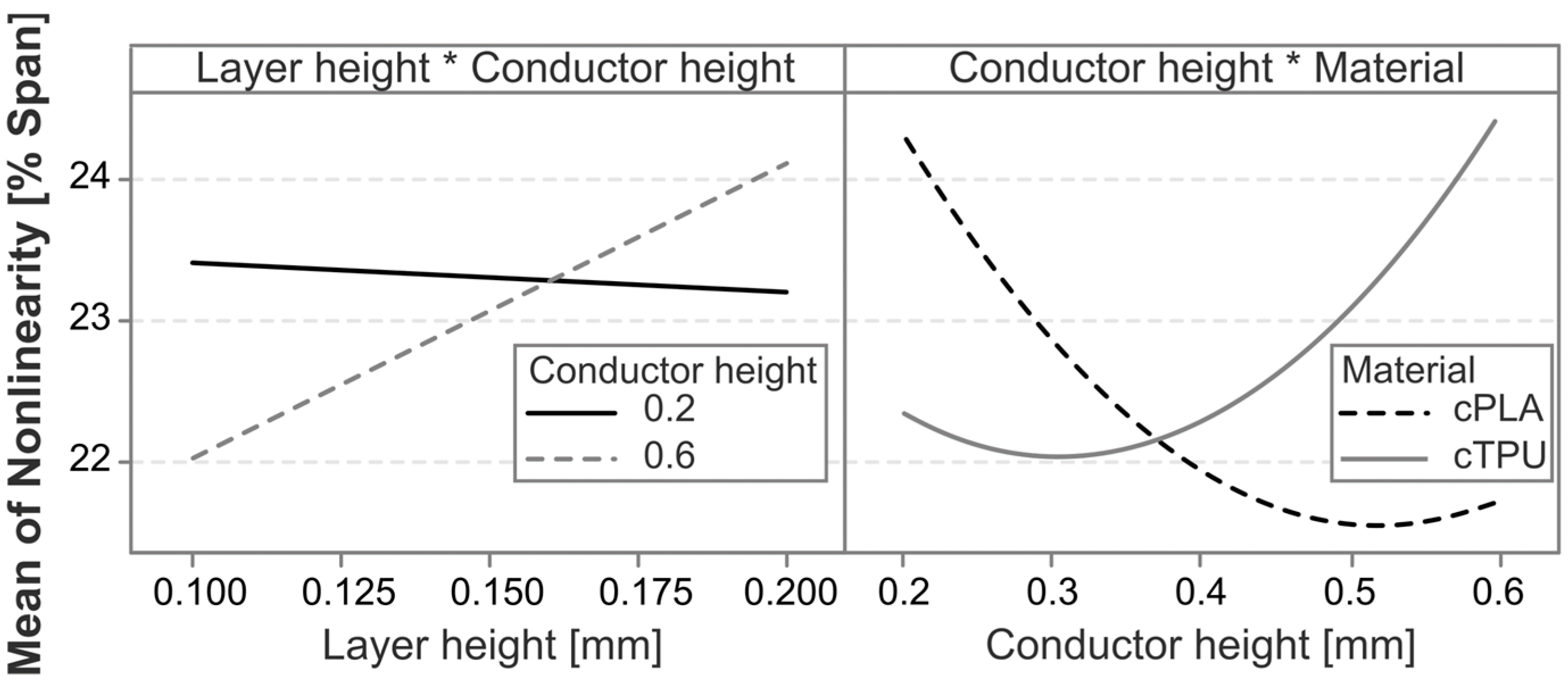
3.1. Nonlinearity Error
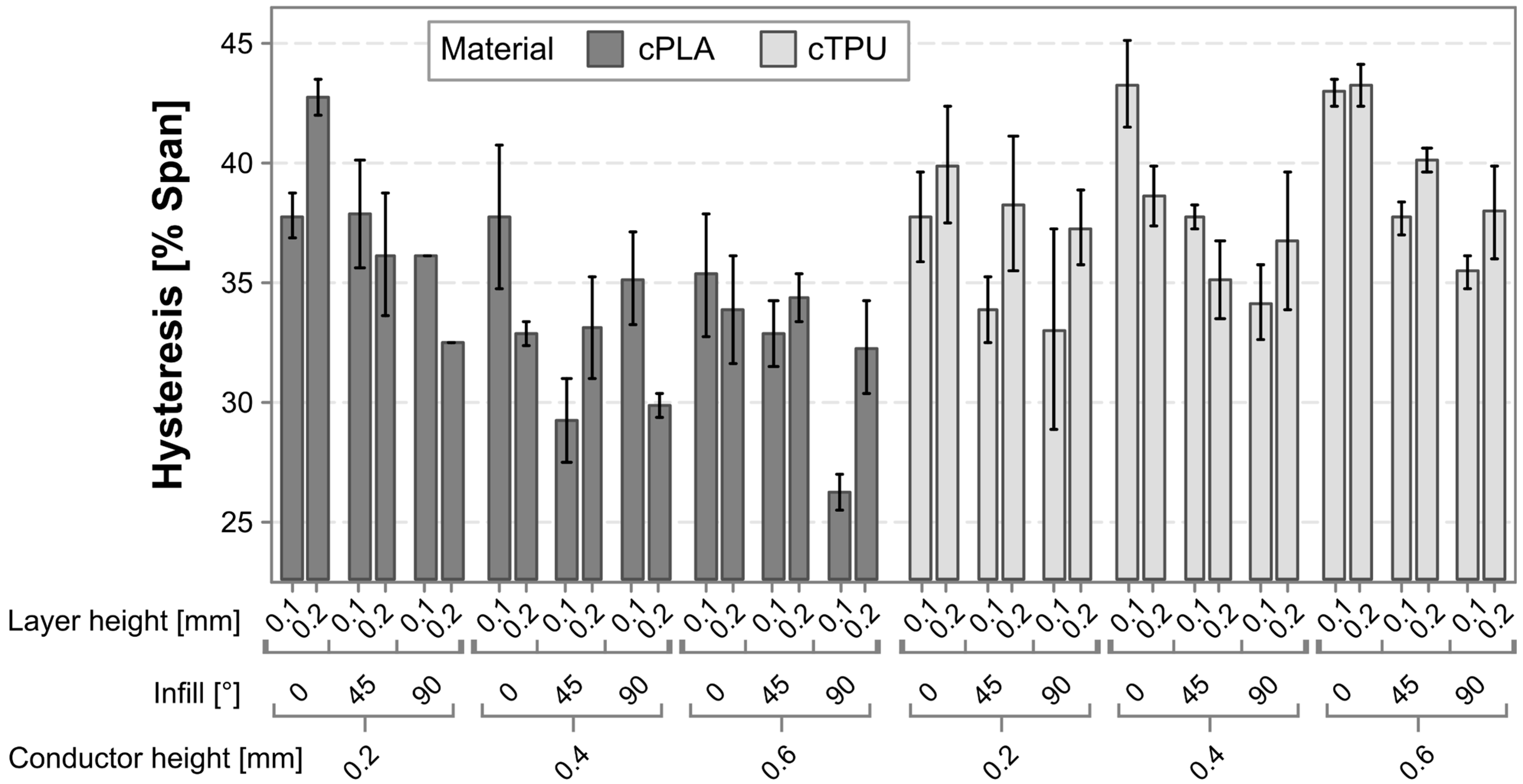
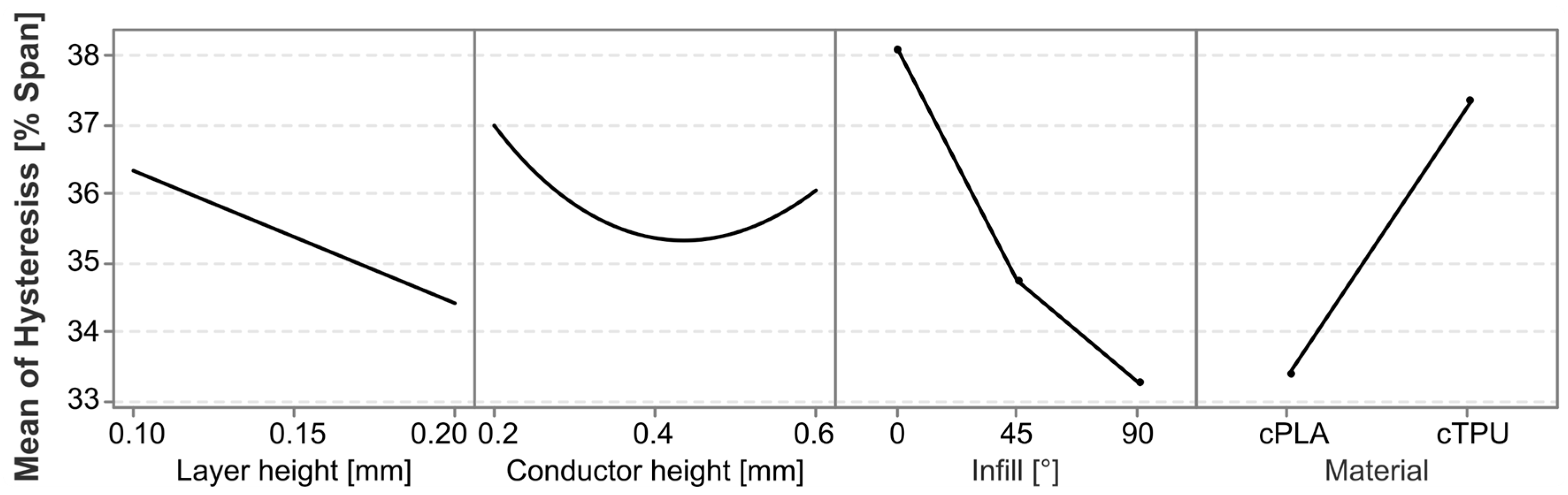
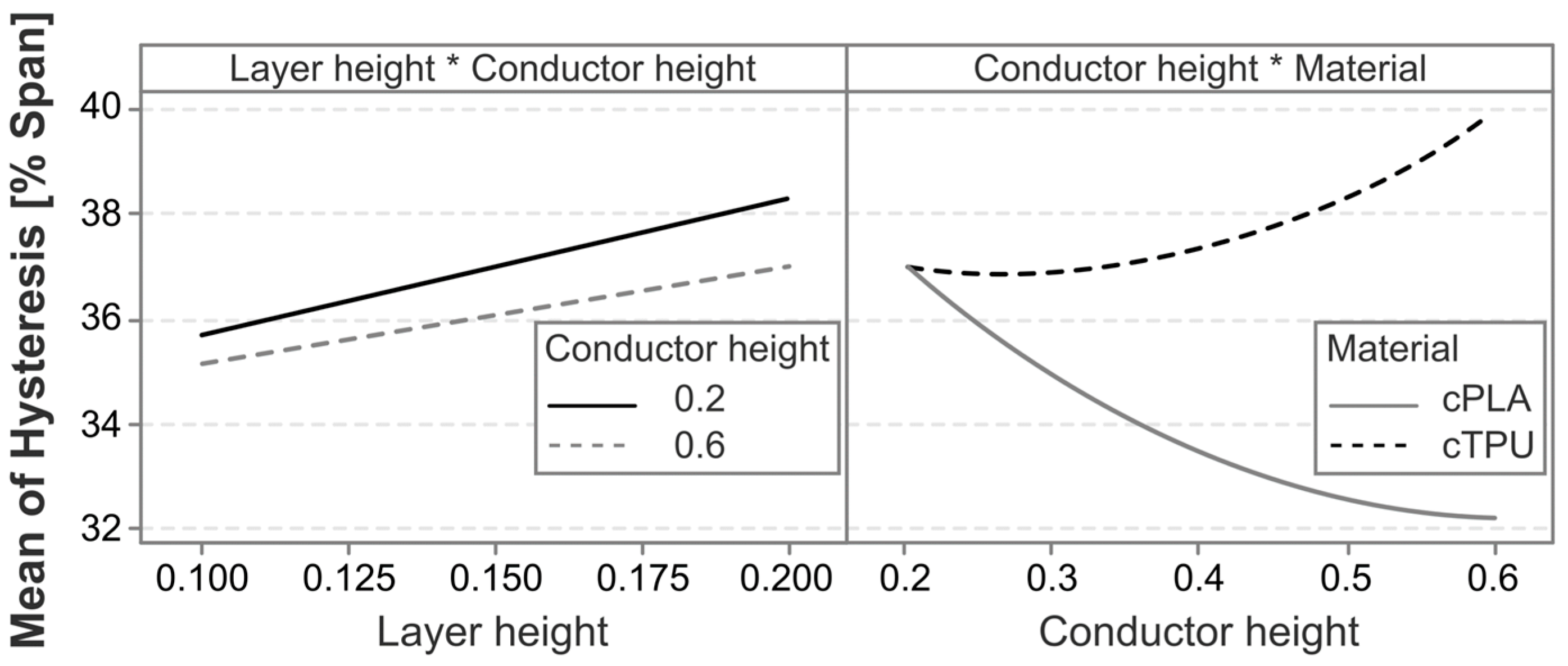
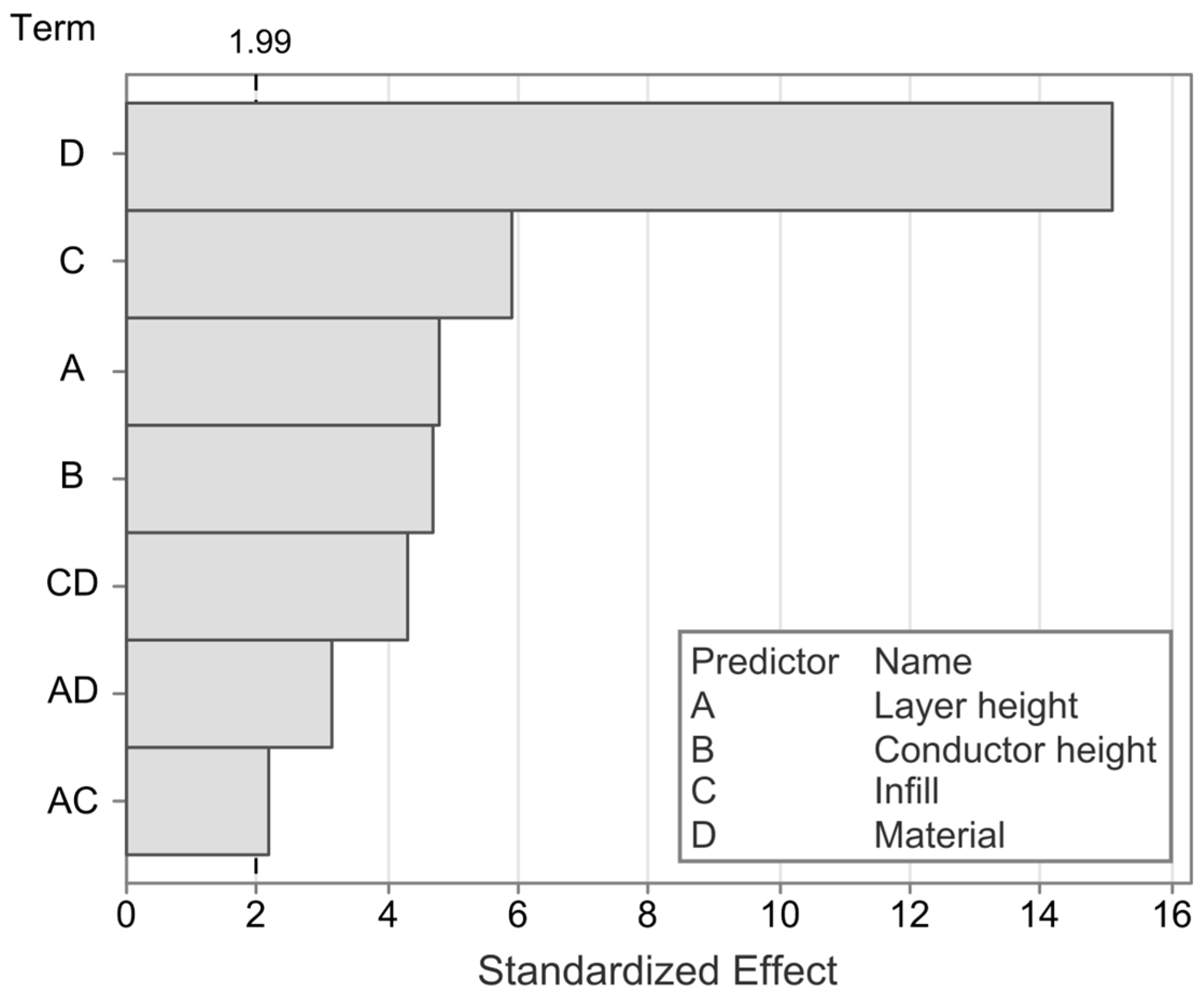
3.2. Hysteresis
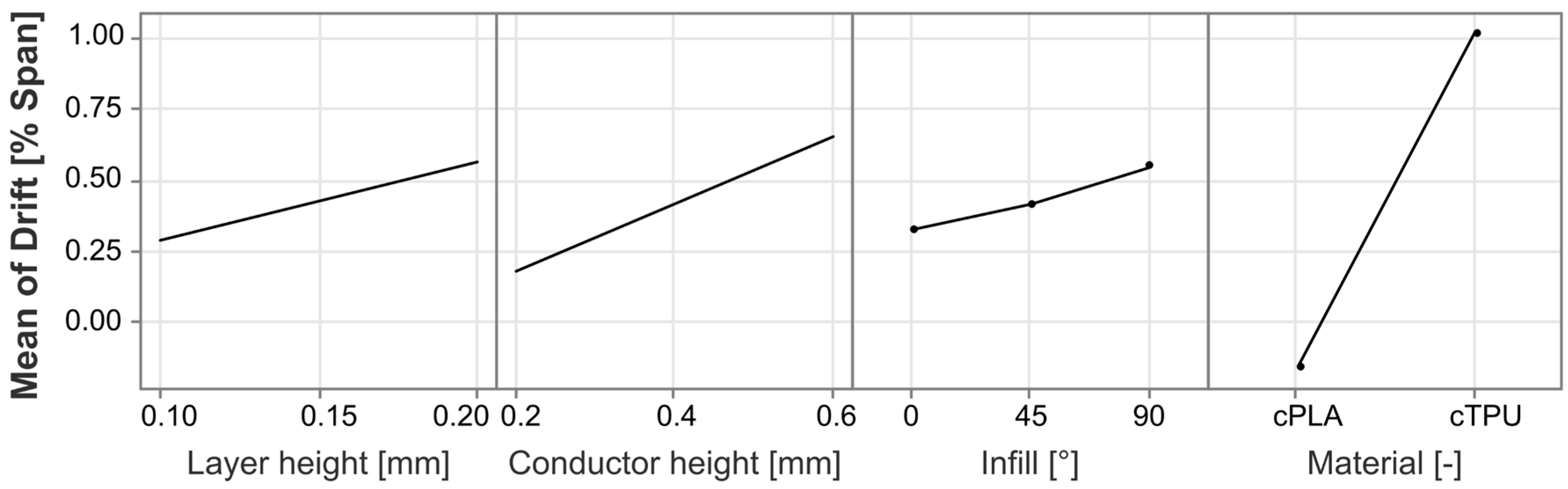
3.3. Drift
4. Conclusions
Author Contributions
Funding
Institutional Review Board Statement
Data Availability Statement
Acknowledgments
Conflicts of Interest
Abbreviations
| AM | Additive manufacturing |
| BFSL | Best fit straight line |
| CI | Confidence interval |
| CPC | Conductive polymer composite |
| cPLA | Conductive polylactic acid |
| cTPU | Conductive thermoplastic polyurethane |
| EPDM | Ethylene propylene diene monomer |
| GF | Gauge factor |
| PLA | Polylactic acid |
| TPU | Thermoplastic polyurethane |
| r | Pearson correlation coefficient |
| R0 | Initial unloaded sensor resistance |
| SEM | Scanning electron microscope |
References
- Gibson, I.; Rosen, D.; Stucker, B.; Khorasani, M. Additive Manufacturing Technologies; Springer International Publishing: Cham, Switzerland, 2021; ISBN 978-3-030-56126-0. [Google Scholar]
- Barši Palmić, T.; Slavič, J.; Boltežar, M. Process Parameters for FFF 3D-Printed Conductors for Applications in Sensors. Sensors 2020, 20, 4542. [Google Scholar] [CrossRef] [PubMed]
- Nowka, M.; Hilbig, K.; Schulze, L.; Heller, T.; Goutier, M.; Vietor, T. Influence of Manufacturing Process on the Conductivity of Material Extrusion Components: A Comparison between Filament- and Granule-Based Processes. Polymers 2024, 16, 1134. [Google Scholar] [CrossRef]
- Ashuri, T.; Armani, A.; Jalilzadeh Hamidi, R.; Reasnor, T.; Ahmadi, S.; Iqbal, K. Biomedical soft robots: Current status and perspective. Biomed. Eng. Lett. 2020, 10, 369–385. [Google Scholar] [CrossRef]
- Abedi, M.; Al-Jabri, K.; Han, B.; Fangueiro, R.; Lourenço, P.B.; Correia, A.G. Advancing infrastructure resilience: A polymeric composite reinforcement grid with self-sensing and self-heating capabilities. Constr. Build. Mater. 2024, 435, 136730. [Google Scholar] [CrossRef]
- Al-Rubaiai, M.; Pinto, T.; Torres, D.; Sepulveda, N.; Tan, X. Characterization of a 3D-Printed Conductive PLA Material With Electrically Controlled Stiffness. In Proceedings of the ASME 2017 Conference on Smart Materials, Adaptive Structures and Intelligent Systems, Snowbird, UT, USA, 18–20 September 2017; The American Society of Mechanical Engineers: New York, NY, USA, 2017. ISBN 978-0-7918-5825-7. [Google Scholar]
- Guadagno, L.; Aliberti, F.; Longo, R.; Raimondo, M.; Pantani, R.; Sorrentino, A.; Catauro, M.; Vertuccio, L. Electrical anisotropy controlled heating of acrylonitrile butadiene styrene 3D printed parts. Mater. Des. 2023, 225, 111507. [Google Scholar] [CrossRef]
- Mirasadi, K.; Rahmatabadi, D.; Ghasemi, I.; Khodaei, M.; Baniassadi, M.; Bodaghi, M.; Baghani, M. 3D and 4D Printing of PETG-ABS-Fe3O4 Nanocomposites with Supreme Remotely Driven Magneto-Thermal Shape-Memory Performance. Polymers 2024, 16, 1398. [Google Scholar] [CrossRef]
- Košir, T.; Slavič, J. Manufacturing of single-process 3D-printed piezoelectric sensors with electromagnetic protection using thermoplastic material extrusion. Addit. Manuf. 2023, 73, 103699. [Google Scholar] [CrossRef]
- Kim, H.; Torres, F.; Wu, Y.; Villagran, D.; Lin, Y.; Tseng, T.-L. Integrated 3D printing and corona poling process of PVDF piezoelectric films for pressure sensor application. Smart Mater. Struct. 2017, 26, 85027. [Google Scholar] [CrossRef]
- Monroe, M.M.; Fumeaux, N.; Villanueva, L.G.; Briand, D. Additively Manufactured Degradable Piezoelectric Microsystems for Sensing and Actuating. Adv. Mater. Technol. 2024, 9, 2300745. [Google Scholar] [CrossRef]
- Nassar, H.; Khandelwal, G.; Chirila, R.; Karagiorgis, X.; Ginesi, R.E.; Dahiya, A.S.; Dahiya, R. Fully 3D printed piezoelectric pressure sensor for dynamic tactile sensing. Addit. Manuf. 2023, 71, 103601. [Google Scholar] [CrossRef]
- Schouten, M.; Sanders, R.; Krijnen, G. 3D printed flexible capacitive force sensor with a simple micro-controller based readout. In Proceedings of the 2017 IEEE SENSORS, Glasgow, UK, 29 October–1 November 2017; IEEE: Piscataway, NJ, USA, 2017; pp. 1–3, ISBN 978-1-5090-1012-7. [Google Scholar]
- Wolterink, G.; Sanders, R.; Krijnen, G. Thin, Flexible, Capacitive Force Sensors Based on Anisotropy in 3D-Printed Structures. In Proceedings of the 2018 IEEE Sensors, New Delhi, India, 28–31 October 2018; IEEE: Piscataway, NJ, USA, 2018; pp. 1–4, ISBN 978-1-5386-4707-3. [Google Scholar]
- Hohimer, C.J.; Petrossian, G.; Ameli, A.; Mo, C.; Pötschke, P. 3D printed conductive thermoplastic polyurethane/carbon nanotube composites for capacitive and piezoresistive sensing in soft pneumatic actuators. Addit. Manuf. 2020, 34, 101281. [Google Scholar] [CrossRef]
- Arh, M.; Slavič, J.; Boltežar, M. Design principles for a single-process 3d-printed accelerometer—Theory and experiment. Mech. Syst. Signal Process. 2021, 152, 107475. [Google Scholar] [CrossRef]
- Leigh, S.J.; Bradley, R.J.; Purssell, C.P.; Billson, D.R.; Hutchins, D.A. A simple, low-cost conductive composite material for 3D printing of electronic sensors. PLoS ONE 2012, 7, e49365. [Google Scholar] [CrossRef] [PubMed]
- Georgopoulou, A.; Clemens, F. Piezoresistive Elastomer-Based Composite Strain Sensors and Their Applications. ACS Appl. Electron. Mater. 2020, 2, 1826–1842. [Google Scholar] [CrossRef]
- Xiang, D.; Zhang, X.; Han, Z.; Zhang, Z.; Zhou, Z.; Harkin-Jones, E.; Zhang, J.; Luo, X.; Wang, P.; Zhao, C.; et al. 3D printed high-performance flexible strain sensors based on carbon nanotube and graphene nanoplatelet filled polymer composites. J. Mater. Sci. 2020, 55, 15769–15786. [Google Scholar] [CrossRef]
- Goutier, M.; Hilbig, K.; Vietor, T.; Böl, M. Process Parameters and Geometry Effects on Piezoresistivity in Additively Manufactured Polymer Sensors. Polymers 2023, 15, 2159. [Google Scholar] [CrossRef]
- Watschke, H.; Goutier, M.; Heubach, J.; Vietor, T.; Leichsenring, K.; Böl, M. Novel Resistive Sensor Design Utilizing the Geometric Freedom of Additive Manufacturing. Appl. Sci. 2021, 11, 113. [Google Scholar] [CrossRef]
- Glogowsky, A.; Korger, M.; Rabe, M. Influence of print settings on conductivity of 3D printed elastomers with carbon-based fillers. Prog. Addit. Manuf. 2024, 9, 791–803. [Google Scholar] [CrossRef]
- Watschke, H.; Hilbig, K.; Vietor, T. Design and Characterization of Electrically Conductive Structures Additively Manufactured by Material Extrusion. Appl. Sci. 2019, 9, 779. [Google Scholar] [CrossRef]
- Hampel, B.; Monshausen, S.; Schilling, M. Properties and applications of electrically conductive thermoplastics for additive manufacturing of sensors. Tech. Messen. 2017, 84, 593–599. [Google Scholar] [CrossRef]
- Arh, M.; Slavič, J.; Boltežar, M. Experimental identification of the dynamic piezoresistivity of fused-filament-fabricated structures. Addit. Manuf. 2020, 36, 101493. [Google Scholar] [CrossRef]
- Mousavi, S.; Howard, D.; Zhang, F.; Leng, J.; Wang, C.H. Direct 3D Printing of Highly Anisotropic, Flexible, Constriction-Resistive Sensors for Multidirectional Proprioception in Soft Robots. ACS Appl. Mater. Interfaces 2020, 12, 15631–15643. [Google Scholar] [CrossRef]
- Mousavi, S.; Blanloeuil, P.; Vinoth, T.; Howard, D.; Wang, C.H. A 3D Printed, Constriction-Resistive Sensor for the Detection of Ultrasonic Waves. In Structural Health Monitoring, Proceedings of the Structural Health Monitoring; Materials Research Forum LLC: Millersville PA, USA, 2021; pp. 272–277. [Google Scholar]
- Shin, S.; Ko, B.; So, H. Structural effects of 3D printing resolution on the gauge factor of microcrack-based strain gauges for health care monitoring. Microsyst. Nanoeng. 2022, 8, 12. [Google Scholar] [CrossRef]
- Gooding, J.; Fields, T. 3D Printed Strain Gauge Geometry and Orientation for Embedded Sensing. In Proceedings of the 58th AIAA/ASCE/AHS/ASC Structures Structural Dynamics and Materials Conference, Grapevine, TX, USA, 9–13 January 2017; American Institute of Aeronautics and Astronautics: Reston, VA, USA, 2017. ISBN 978-1-62410-453-4. [Google Scholar]
- Hernandez, J.A.; Maynard, C.; Gonzalez, D.; Viz, M.; O’Brien, C.; Garcia, J.; Newell, B.; Tallman, T.N. The development and characterization of carbon nanofiber/polylactic acid filament for additively manufactured piezoresistive sensors. Addit. Manuf. 2022, 58, 102948. [Google Scholar] [CrossRef]
- Stano, G.; Di Nisio, A.; Lanzolla, A.; Percoco, G. Additive manufacturing and characterization of a load cell with embedded strain gauges. Precis. Eng. 2020, 62, 113–120. [Google Scholar] [CrossRef]
- Xu, J.; Doubrovski, Z.; Ozdemir, M.; Geraedts, J.M.; Song, Y. Development of a 3D printed structural electronics force sensor. IEEE Access 2024, 12, 58551–58561. [Google Scholar] [CrossRef]
- Amjadi, M.; Kyung, K.-U.; Park, I.; Sitti, M. Stretchable, Skin-Mountable, and Wearable Strain Sensors and Their Potential Applications: A Review. Adv. Funct. Mater. 2016, 26, 1678–1698. [Google Scholar] [CrossRef]
- Avilés, F.; Oliva-Avilés, A.I.; Cen-Puc, M. Piezoresistivity, Strain, and Damage Self-Sensing of Polymer Composites Filled with Carbon Nanostructures. Adv. Eng. Mater. 2018, 20, 1701159. [Google Scholar] [CrossRef]
- Schouten, M.; Prakken, B.; Sanders, R.; Krijnen, G. Linearisation of a 3D printed flexible tactile sensor based on piezoresistive sensing. In Proceedings of the 2019 IEEE SENSORS, Montreal, QC, Canada, 27–30 October 2019; IEEE: Piscataway, NJ, USA, 2019; pp. 1–4, ISBN 978-1-7281-1634-1. [Google Scholar]
- Abshirini, M.; Charara, M.; Liu, Y.; Saha, M.C.; Altan, M.C. Additive Manufacturing of Polymer Nanocomposites With In-Situ Strain Sensing Capability. In Proceedings of the ASME 2018 International Mechanical Engineering Congress and Exposition, Pittsburgh, PA, USA, 9–15 November 2018; The American Society of Mechanical Engineers: New York, NY, USA, 2019. ISBN 978-0-7918-5217-0. [Google Scholar]
- Ahmed, S.; Bodaghi, M.; Nauman, S.; Muhammad Khan, Z. Additive Manufacturing of Flexible Strain Sensors Based on Smart Composites for Structural Health Monitoring with High Accuracy and Fidelity. Adv. Eng. Mater. 2023, 25, 2300763. [Google Scholar] [CrossRef]
- Al-Rubaiai, M.; Tsuruta, R.; Gandhi, U.; Wang, C.; Tan, X. A 3D-printed stretchable strain sensor for wind sensing. Smart Mater. Struct. 2019, 28, 84001. [Google Scholar] [CrossRef]
- Giffney, T.; Bejanin, E.; Kurian, A.S.; Travas-Sejdic, J.; Aw, K. Highly stretchable printed strain sensors using multi-walled carbon nanotube/silicone rubber composites. Sens. Actuators A Phys. 2017, 259, 44–49. [Google Scholar] [CrossRef]
- Grønborg, F.; Zsurzsan, T.G.; Daugaard, A.E.; Spangenberg, J.; Pedersen, D.B. Conductive compliant mechanisms: Geometric tuning of 3D printed flexural sensors. Addit. Manuf. Lett. 2022, 3, 100088. [Google Scholar] [CrossRef]
- Kim, K.; Park, J.; Suh, J.; Kim, M.; Jeong, Y.; Park, I. 3D printing of multiaxial force sensors using carbon nanotube (CNT)/thermoplastic polyurethane (TPU) filaments. Sens. Actuators A Phys. 2017, 263, 493–500. [Google Scholar] [CrossRef]
- Kosmas, D.; Schouten, M.; Krijnen, G. Hysteresis Compensation of 3D Printed Sensors by a Power Law Model with Reduced Parameters. In Proceedings of the 2020 IEEE International Conference on Flexible and Printable Sensors and Systems (FLEPS), Manchester, UK, 16–19 August 2020; IEEE: Piscataway, NJ, USA, 2020; pp. 1–4, ISBN 978-1-7281-5278-3. [Google Scholar]
- Lanzolla, A.M.L.; Attivissimo, F.; Percoco, G.; Ragolia, M.A.; Stano, G.; Di Nisio, A. Additive Manufacturing for Sensors: Piezoresistive Strain Gauge with Temperature Compensation. Appl. Sci. 2022, 12, 8607. [Google Scholar] [CrossRef]
- Liu, H.; Zhang, H.; Han, W.; Lin, H.; Li, R.; Zhu, J.; Huang, W. 3D Printed Flexible Strain Sensors: From Printing to Devices and Signals. Adv. Mater. Weinheim. 2021, 33, e2004782. [Google Scholar] [CrossRef]
- Ntagios, M.; Nassar, H.; Pullanchiyodan, A.; Navaraj, W.T.; Dahiya, R. Robotic Hands with Intrinsic Tactile Sensing via 3D Printed Soft Pressure Sensors. Adv. Intell. Syst. 2020, 2, 1900080. [Google Scholar] [CrossRef]
- Xiang, D.; Zhang, X.; Li, Y.; Harkin-Jones, E.; Zheng, Y.; Wang, L.; Zhao, C.; Wang, P. Enhanced performance of 3D printed highly elastic strain sensors of carbon nanotube/thermoplastic polyurethane nanocomposites via non-covalent interactions. Compos. Part. B Eng. 2019, 176, 107250. [Google Scholar] [CrossRef]
- Stübler, N.; Fritzsche, J.; Klüppel, M. Mechanical and electrical analysis of carbon black networking in elastomers under strain. Polym. Eng. Sci. 2011, 51, 1206–1217. [Google Scholar] [CrossRef]
- Li, J.; Fang, L.; Sun, B.; Li, X.; Kang, S.H. Review—Recent Progress in Flexible and Stretchable Piezoresistive Sensors and Their Applications. J. Electrochem. Soc. 2020, 167, 37561. [Google Scholar] [CrossRef]
- Mu, Q.; Hu, T.; Tian, X.; Li, T.; Kuang, X. The Effect of Filler Dimensionality and Content on Resistive Viscoelasticity of Conductive Polymer Composites for Soft Strain Sensors. Polymers 2023, 15, 3379. [Google Scholar] [CrossRef]
- Georgopoulou, A.; Clemens, F. Pellet-based fused deposition modeling for the development of soft compliant robotic grippers with integrated sensing elements. Flex. Print. Electron. 2022, 7, 25010. [Google Scholar] [CrossRef]
- Shui, X.; Chung, D.D.L. A piezoresistive carbon filament polymer-matrix composite strain sensor. Smart Mater. Struct. 1996, 5, 243–246. [Google Scholar] [CrossRef]
- Karabal, M.; Yuksel, R.; Kayginok, F.; Yildiz, A.; Cebeci, H. Embedded Piezoresistive Sensors Printed by FFF for Aerospace Applications. In Proceedings of the AIAA SCITECH 2023 Forum, National Harbor, MD, USA, 23–27 January 2023; American Institute of Aeronautics and Astronautics: Reston, VA, USA, 2023. ISBN 978-1-62410-699-6. [Google Scholar]
- Klimm, W.; Kwok, K. Mechanism of resistance relaxation and hysteresis in viscoelastic piezoresistive polymer nanocomposites. Int. J. Mech. Mater. Des. 2022, 18, 769–783. [Google Scholar] [CrossRef]
- Muller, V.; Fritzsche, M.; Elkmann, N. Sensor design and calibration of piezoresistive composite material. In Proceedings of the 2015 IEEE SENSORS, Busan, Republic of Korea, 1–4 November 2015; IEEE: Piscataway, NJ, USA, 2015; pp. 1–4, ISBN 978-1-4799-8203-5. [Google Scholar]
- Munasinghe, N.; Woods, M.; Miles, L.; Paul, G. 3-D Printed Strain Sensor for Structural Health Monitoring. In Proceedings of the 2019 IEEE International Conference on Cybernetics and Intelligent Systems (CIS) and IEEE Conference on Robotics, Automation and Mechatronics (RAM), Bangkok, Thailand, 18–20 November 2019; pp. 275–280, ISBN 978-1-7281-3458-1. [Google Scholar]
- Proto-Pasta. Proto-Pasta Conductive PLA Technical Data Sheet. Available online: https://cdn.shopify.com/s/files/1/0717/9095/files/TDS__Conductive_PLA_1.0.1.pdf (accessed on 29 October 2024).
- NinjaTek. Eel 3D Printing Filament Technical Datasheet. Available online: https://ninjatek.com/wp-content/uploads/Eel-TDS.pdf (accessed on 15 April 2025).
- Proto-Pasta. Composite Conductive Fiber PLA Safety Data Sheet. Available online: https://cdn.shopify.com/s/files/1/0717/9095/files/CDP1xxxx_SDS.pdf (accessed on 26 June 2023).
- NinjaTek. EEL 3D Filament Safety Data Sheet. Available online: https://ninjatek.com/wp-content/uploads/SDS_EEL.pdf (accessed on 15 April 2025).
- Nowka, M.; Ruge, K.; Schulze, L.; Hilbig, K.; Vietor, T. Characterization of the Anisotropic Electrical Properties of Additively Manufactured Structures Made from Electrically Conductive Composites by Material Extrusion. Polymers 2024, 16, 2891. [Google Scholar] [CrossRef]
- DIN EN ISO 20753; Plastics—Test Specimens; International Organization for Standardization: Geneva, Switzerland, 2018.
- NinjaTek. Technical Data Sheet—NinjaFlex 85A by NinjaTek. Available online: https://ninjatek.com/wp-content/uploads/NinjaFlex-TDS.pdf (accessed on 8 June 2025).
- Schouten, M.; Wolterink, G.; Dijkshoorn, A.; Kosmas, D.; Stramigioli, S.; Krijnen, G. A Review of Extrusion-Based 3D Printing for the Fabrication of Electro-and Biomechanical Sensors. IEEE Sens. J. 2020, 21, 12900–12912. [Google Scholar] [CrossRef]
- DIN EN ISO 7500-1; Metallic Materials—Calibration and Verification of Static Uniaxial Testing Machines—Part 1: Tension/Compression Testing Machines—Calibration and Verification of the Force-Measuring System. International Organization for Standardization: Geneva, Switzerland, 2018.
- DIN EN ISO 527-1; Plastics—Determination of Tensile Properties—Part 1: General Principles. International Organization for Standardization: Geneva, Switzerland, 2019.
- Scholle, P.; Rüther, S.; Sinapius, M. Comparison of Electrical Contacting Techniques to Carbon Fiber Reinforced Plastics for Self-Strain-Sensing Applications. C 2021, 7, 81. [Google Scholar] [CrossRef]
- Regtien, P.P.L. Sensors for Mechatronics; Elsevier: London, UK, 2012; ISBN 9780123944092. [Google Scholar]
- Amjadi, M.; Yoon, Y.J.; Park, I. Ultra-stretchable and skin-mountable strain sensors using carbon nanotubes-Ecoflex nanocomposites. Nanotechnology 2015, 26, 375501. [Google Scholar] [CrossRef]
- Beutier, C.; David, L.; Sudre, G.; Cassagnau, P.; Heuillet, P.; Cantaloube, B.; Serghei, A. In-situ coupled mechanical/electrical investigations of EPDM/CB composite materials: The electrical signature of the mechanical Mullins effect. Compos. Sci. Technol. 2022, 218, 109144. [Google Scholar] [CrossRef]
- Dijkshoorn, A.; Cui, J.; Stramigioli, S.; Krijnen, G. First results of a Soft, 3D-Printed, Resistive Cantilever Flow Sensor. In Proceedings of the 2021 IEEE International Conference on Flexible and Printable Sensors and Systems (FLEPS), Manchester, UK, 20–23 June 2021; IEEE: Piscataway, NJ, USA, 2021; pp. 1–4, ISBN 978-1-7281-9173-7. [Google Scholar]
- Georgopoulou, A.; Vanderborght, B.; Clemens, F. Multi-material 3D Printing of Thermoplastic Elastomers for Development of Soft Robotic Structures with Integrated Sensor Elements. In Industrializing Additive Manufacturing; Meboldt, M., Klahn, C., Eds.; Springer International Publishing: Cham, Switzerland, 2021; pp. 67–81. ISBN 978-3-030-54333-4. [Google Scholar]


| Setting | Unit | TPU | cPLA | cTPU |
|---|---|---|---|---|
| Extrusion temperature | °C | 235 | 235 | 235 |
| Speed | mm/s | 20 | 15 | 20 |
| Extrusion multiplier | - | 1.02 | 0.94 | 1.05 |
| Trace width | mm | 0.4 | 0.4 | 0.4 |
| Shells | - | 2 | 0 | 0 |
| Bed temperature | °C | 40 | 40 | 40 |
Disclaimer/Publisher’s Note: The statements, opinions and data contained in all publications are solely those of the individual author(s) and contributor(s) and not of MDPI and/or the editor(s). MDPI and/or the editor(s) disclaim responsibility for any injury to people or property resulting from any ideas, methods, instructions or products referred to in the content. |
© 2025 by the authors. Licensee MDPI, Basel, Switzerland. This article is an open access article distributed under the terms and conditions of the Creative Commons Attribution (CC BY) license (https://creativecommons.org/licenses/by/4.0/).
Share and Cite
Goutier, M.; Vietor, T. Parametric Study of Geometry and Process Parameter Influences on Additively Manufactured Piezoresistive Sensors Under Cyclic Loading. Polymers 2025, 17, 1625. https://doi.org/10.3390/polym17121625
Goutier M, Vietor T. Parametric Study of Geometry and Process Parameter Influences on Additively Manufactured Piezoresistive Sensors Under Cyclic Loading. Polymers. 2025; 17(12):1625. https://doi.org/10.3390/polym17121625
Chicago/Turabian StyleGoutier, Marijn, and Thomas Vietor. 2025. "Parametric Study of Geometry and Process Parameter Influences on Additively Manufactured Piezoresistive Sensors Under Cyclic Loading" Polymers 17, no. 12: 1625. https://doi.org/10.3390/polym17121625
APA StyleGoutier, M., & Vietor, T. (2025). Parametric Study of Geometry and Process Parameter Influences on Additively Manufactured Piezoresistive Sensors Under Cyclic Loading. Polymers, 17(12), 1625. https://doi.org/10.3390/polym17121625