

Experimental Study of a 3D Printing Strategy for Polymer-Based Parts for Drone Equipment Using Bladeless Technology


Abstract

1. Introduction
2. Theoretical Aspects
2.1. Calculus of the Motors
- Gravitational force.
- Drag force.
- Total force required.
- Motor rotation speed (at the shaft).
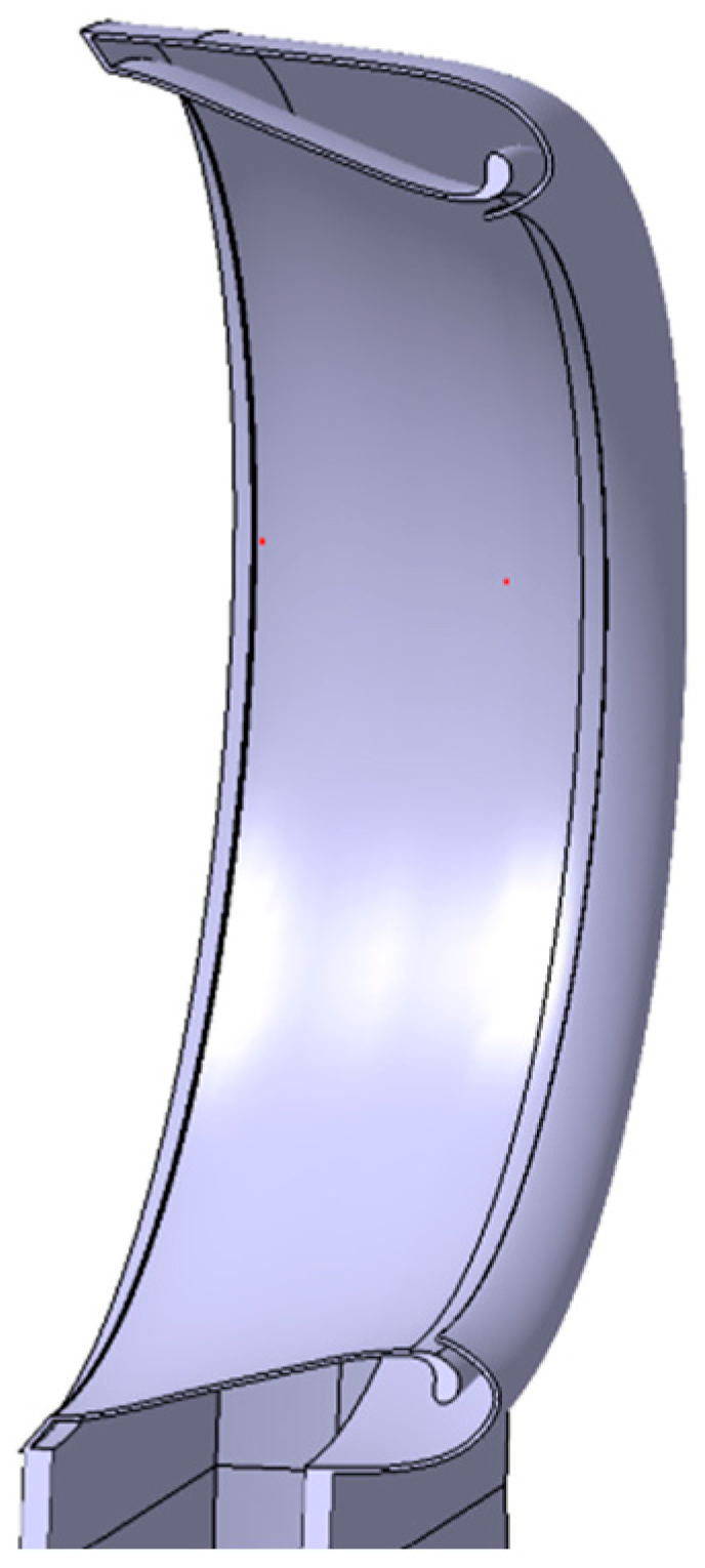
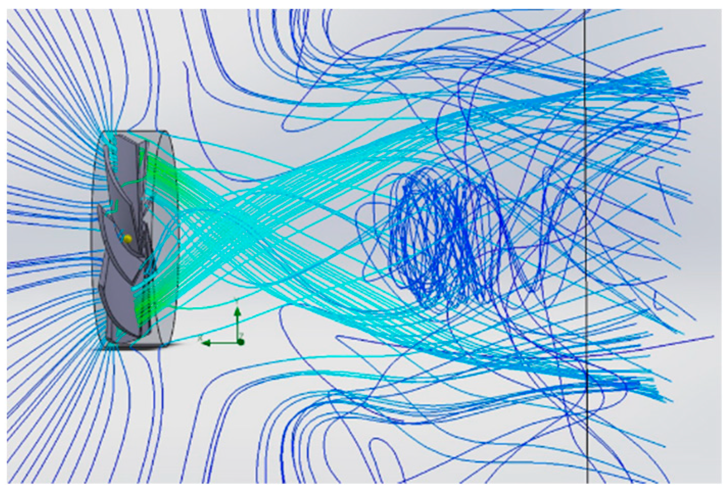
2.2. Presentation of the 3D Model
3. Practical Development of the Drone
- The structure must exhibit a high level of rigidity.
- The assembly must have a low mass.
- Surface quality must be adequate, particularly on surfaces in contact with air currents.
- Components must be capable of withstanding specific loads.
- Prototyping should prevent issues from arising at contact surfaces with components or fasteners made from different materials.
- Efficient and easy assembly must be facilitated by the surfaces on which the attachment is carried out.
- The propulsion system of the assembly must provide superior thrust force values compared to those provided by the established method used by drones currently available on the market.
- The motion model must provide dynamic behavior capabilities at least equivalent to those of current multi-rotor type drones.
- The sound signature of the concept should exploit the quietness of the “Air Multiplier” technology, offering the alternative of a flying machine with a reduced noise level.
- The level of safety required must be high, given that the blades are embedded in the propeller body.
- The assembly must offer a low energy consumption for an equivalent value of propulsion force compared to usual drones.
- The assembly must offer good maneuverability.
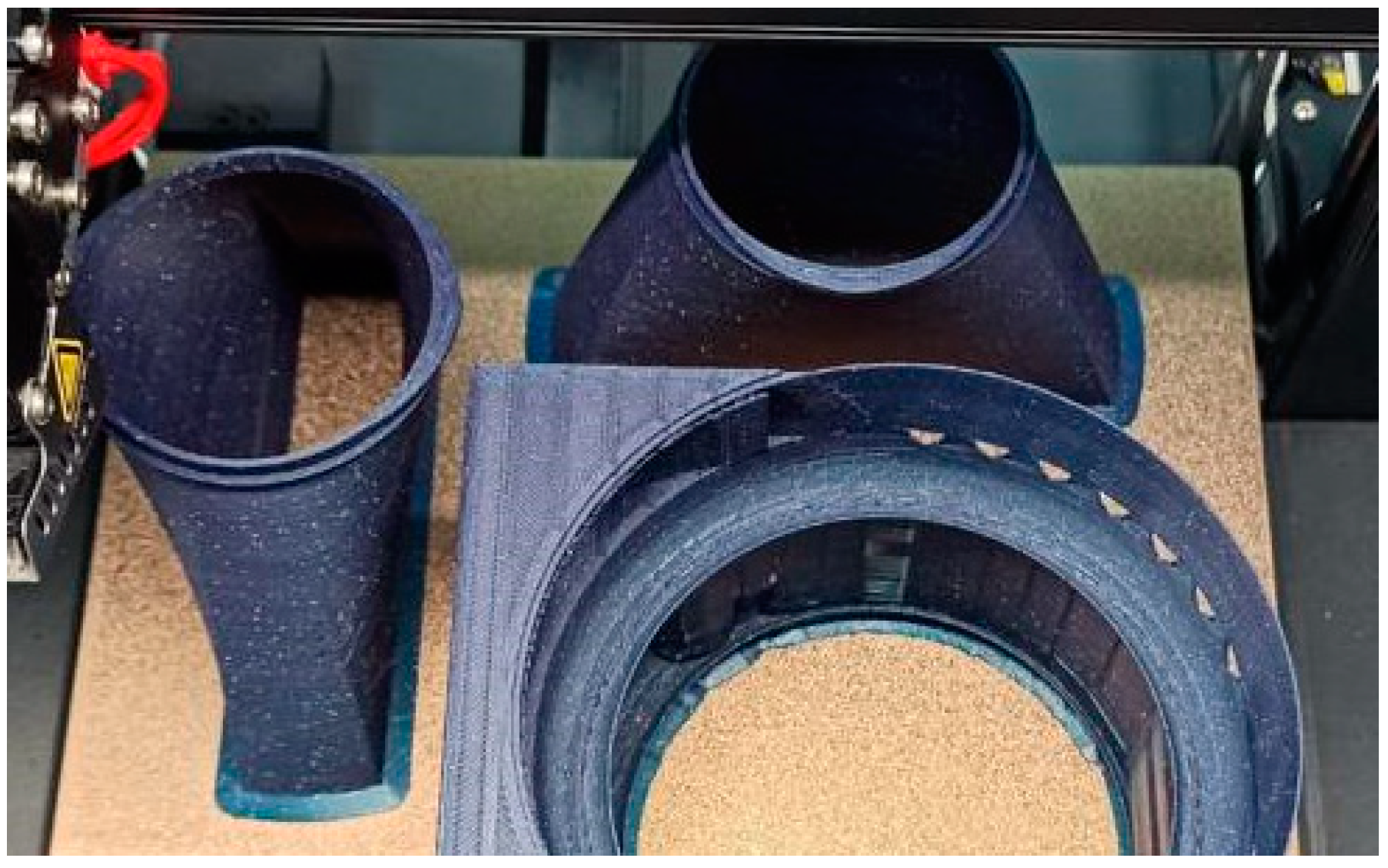
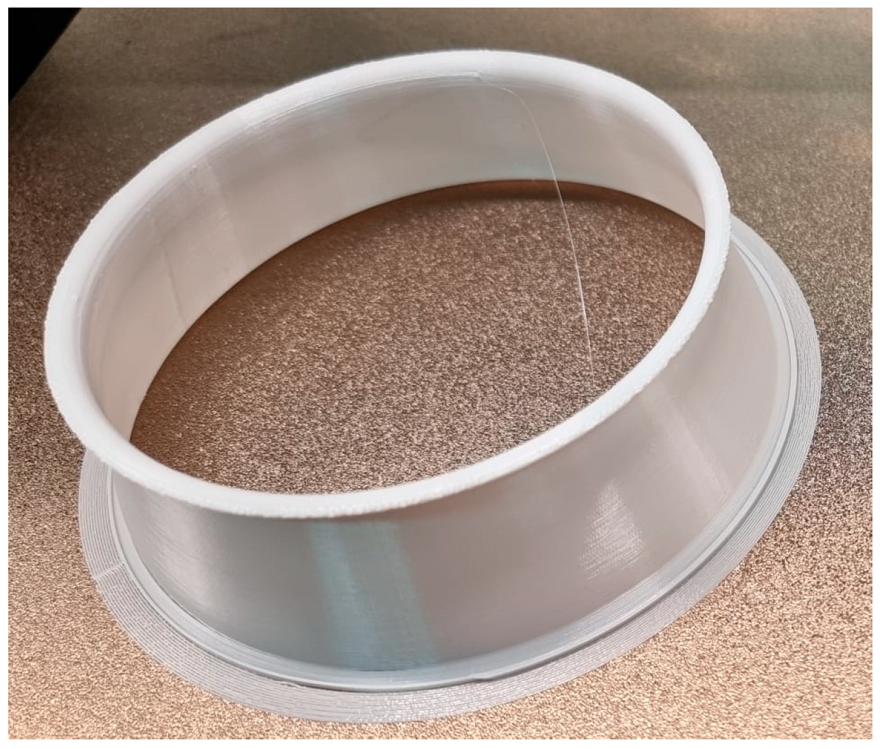
The Prototyping and Assembly of the Model
4. Conclusions
Author Contributions
Funding
Institutional Review Board Statement
Data Availability Statement
Conflicts of Interest
References
- Pringle, A.M.; Rudnicki, M.; Pearce, J.M. Wood Furniture Waste-Based Recycled 3-D Printing Filament. For. Prod. J. 2017, 68, 86–95. [Google Scholar] [CrossRef]
- Calì, M.; Pascoletti, G.; Gaeta, M.; Milazzo, G.; Ambu, R. A New Generation of Bio-Composite Thermoplastic Filaments for a More Sustainable Design of Parts Manufactured by FDM. Appl. Sci. 2020, 10, 5852. [Google Scholar] [CrossRef]
- Sharma, V.; Roozbahani, H.; Alizadeh, M.; Handroos, H. 3D Printing of Plant-Derived Compounds and a Proposed Nozzle Design for the More Effective 3D FDM Printing. IEEE Access 2021, 9, 57107–57119. [Google Scholar] [CrossRef]
- Gardner, D.; Anderson, J.; Tekinalp, H.; Ozcan, S.; Sauerbier, P. Lignocellulosic-filled polymer feedstocks for large scale additive manufacturing of low cost composites. In Proceedings of the International Forest Products Congress, Trabzon, Turkey, 26–29 September 2018; pp. 26–29. [Google Scholar]
- Velu, R.; Raspall, F.; Singamneni, S. Chapter 8—3D printing technologies and composite materials for structural applications. In Green Composites for Automotive Applications; Woodhead Publishing: Sawston, UK, 2019; pp. 171–196. [Google Scholar]
- Rajak, D.K.; Wagh, P.H.; Linul, E. A Review on Synthetic Fibers for Polymer Matrix Composites: Performance, Failure Modes and Applications. Materials 2022, 15, 4790. [Google Scholar] [CrossRef] [PubMed]
- Zhang, H.; Huang, T.; Jiang, Q.; He, L.; Bismarck, A.; Hu, Q. Recent progress of 3D printed continuous fiber reinforced polymer composites based on fused deposition modeling: A review. J. Mater. Sci. 2021, 56, 12999–13022. [Google Scholar] [CrossRef]
- Valvez, S.; dos Santos, P.S.P.; Parente, J.; Silva, M.; Reis, P. 3D printed continuous carbon fiber reinforced PLA composites: A short review. Procedia Struct. Integr. 2020, 25, 394–399. [Google Scholar] [CrossRef]
- Hikmat, M.; Rostam, S.; Ahmed, Y.M. Investigation of tensile property-based Taguchi method of PLA parts fabricated by FDM 3D printing technology. Results Eng. 2021, 11, 100264. [Google Scholar] [CrossRef]
- Hsueh, M.-H.; Lai, C.-J.; Wang, S.-H.; Zeng, Y.-S.; Hsieh, C.-H.; Pan, C.-Y.; Huang, W.-C. Effect of Printing Parameters on the Thermal and Mechanical Properties of 3D-Printed PLA and PETG, Using Fused Deposition Modeling. Polymers 2021, 13, 1758. [Google Scholar] [CrossRef] [PubMed]
- Gammack, P.D.; Nicolas, F.; Simmonds, K.J. A Fan. European Patent EP2232077B1, 20 April 2011. Available online: https://patents.google.com/patent/EP2232077B1 (accessed on 15 October 2022).
- Dyson Air Multiplier. Available online: https://media.dyson.com/downloads/uk/fan/fanCommercialUK.pdf (accessed on 16 October 2022).
- The Sun. Dyson Fans Are Well Engineered and Use Power Very Efficiently. Available online: https://www.thesun.co.uk/money/19472832/how-much-cost-run-dyson-fan-overnight (accessed on 17 October 2022).
- Pickles, D.J.; Green, R.B.; Busse, A. The vortex ring state of a rotor and its comparison with the collapse of an annular jet in counterflow. Phys. Fluids 2023, 35, 044103. [Google Scholar] [CrossRef]
- Jafari, M.; Afshin, H.; Farhanieh, B.; Bozorgasareh, H. Experimental and Numerical Investigation of a 60 cm Diameter Bladeless Fan. J. Appl. Fluid Mech. 2016, 9, 935–944. Available online: https://www.jafmonline.net/article_1673_3e66870aa0cac45d95ea33e41d0a7d0f.pdf (accessed on 28 October 2022).
- Jetoptera. Available online: https://www.jetoptera.com/products/ (accessed on 2 October 2022).
- Sivaraman, S.; Kumar, V.S.; Santhini, M.; Rajalakshmi, S.; Sittheshwaran, S. An Overview of Bladeless Drone. IJIREEICE 2021, 9, 80–85. [Google Scholar] [CrossRef]
- Xu, H.; Jiang, L.; Cao, Z.; Bao, X. Design study of a rotorless Unmanned Aerial Vehicle. In Proceedings of the 4th International Seminar on Artificial Intelligence, Networking and Information Technology (AINIT), Nanjing, China, 16–18 June 2023. [Google Scholar] [CrossRef]
- Valdenegro, D.; Capunay, A.; Gonzalez, D.; Carrillo, L.R.G.; Rangel, P. Improving Safety: Design and Development of a Bladeless Thruster for Autonomous Multicopters. In Proceedings of the International Conference on Unmanned Aircraft Systems (ICUAS), Dallas, TX, USA, 12–15 June 2018. [Google Scholar] [CrossRef]
- Lumen Learning. Drag Forces. Available online: https://courses.lumenlearning.com/suny-physics/chapter/5-2-drag-forces/ (accessed on 28 October 2022).
- Hoerner, S.F. Fluid-Dynamic Drag. 1965. Available online: https://archive.org/details/FluidDynamicDragHoerner1965/mode/1up (accessed on 28 October 2022).
- Astro Flight. Motor Terminology. Available online: https://www.astroflight.com/explanation-of-motor-terminology.html (accessed on 7 December 2022).
- SVUB05. Brushless Electric Motor MT2204. Available online: https://rcl.lt/products/svub05-variklis-besepetelinis-2300kv-mt2204-rc003-tinka-ir-qav250 (accessed on 7 December 2022).
- Abutha, M.A.; Aparna, R.; Dsouza, A.L.; Kumar, S.; Tejaswini, G. Development of Bladeless Thruster for an UAV Application. JETIR 2020, 7, 856–864. [Google Scholar]
- Aqilah, F.; Islam, M.; Juretic, F.; Guerrero, J.; Wood, D.; Ani, F. Study of Mesh Quality Improvement for CFD Analysis of an Airfoil. IIUM Eng. J. 2018, 19, 203–212. [Google Scholar] [CrossRef]
- University of British Columbia. Standard Atmosphere Pressure and Density. Available online: https://www.eoas.ubc.ca/courses/atsc113/flying/met_concepts/02-met_concepts/02a-std_atmos-P/index.html (accessed on 11 December 2022).
- Ozsoy, K.; Erçetin, A.; Çevik, Z. Comparison of Mechanical Properties of PLA and ABS Based Structures Produced by Fused Deposition Modelling Additive Manufacturing. Eur. J. Sci. Technol. 2021, 27, 802–809. [Google Scholar] [CrossRef]
- Grgić, I.; Karakašić, M.; Glavaš, H.; Konjatić, P. Accuracy of FDM PLA Polymer 3D Printing Technology Based on Tolerance Fields. Processes 2023, 11, 2810. [Google Scholar] [CrossRef]
- Han, Y.; Song, L.; Du, H.; Wang, G.; Zhang, T.; Ni, L.; Li, Y. Enhancing structural response via macro-micro hierarchy for piezoelectric nanogenerator and self-powered wearable controller. Chem. Eng. J. 2024, 481, 148729. [Google Scholar] [CrossRef]
- Jiang, K.; Wen, X.; Deng, Y.; Zhou, Z.; Weng, Q. Integration of all-printed zinc ion microbattery and glucose sensor toward onsite quick detections. SusMat 2022, 2, 368–378. [Google Scholar] [CrossRef]
- Khosravani, M.R.; Anders, D.; Reinicke, T. Effects of post-processing on the fracture behavior of surface-treated 3D-printed parts. CIRP J. Manuf. Sci. Technol. 2023, 46, 148–156. [Google Scholar] [CrossRef]
- Sebastian, T.; Strem, C. Toroidal Propeller. U.S. Patent US20190135410A1, 17 November 2017. Available online: https://patents.google.com/patent/US20190135410A1/en (accessed on 6 January 2023).
- MIT Lincoln Laboratory. Toroidal Propeller. Available online: https://www.ll.mit.edu/sites/default/files/other/doc/2023-02/TVO_Technology_Highlight_41_Toroidal_Propeller.pdf (accessed on 6 January 2023).
- Nagendra, G.; Tanikella, B.W.; Joshua, M.P. Tensile strength of commercial polymer materials for fused filament fabrication 3D printing. Addit. Manuf. 2017, 15, 40–47. [Google Scholar] [CrossRef]
- Popescu, S.; Rusu, D.; Dragomir, M.; Popescu, D.; Nedelcu, Ș. Competitive Development Tools in Identifying Efficient Educational Interventions for Improving Pro-Environmental and Recycling Behavior. Int. J. Environ. Res. Public Health 2020, 17, 156. [Google Scholar] [CrossRef]


| Basic Mesh Dimensions | Nx = 27, Ny = 52, Nz = 26 |
| Pressure [Pa] | 101,305.44 to 101,345.97 |
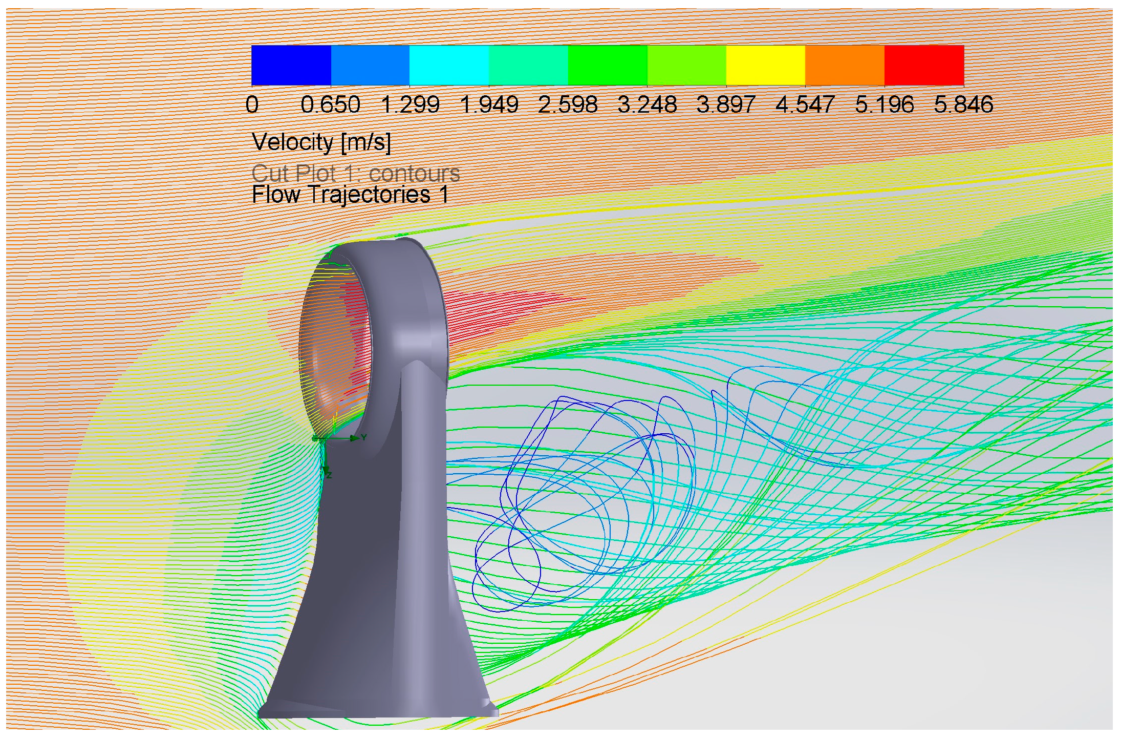
| Velocity [m/s] | 0 to 5.846 |
| Gravity | Yes |
| Temperature [K] | 293.19 to 293.21 |
| Density of Fluid [kg/m3] | 1.20 |
| Reference Pressure [Pa] | 10,1325 |
| Acoustic Power [dB] | 34.21 |
| Shear Stress [Pa] | 0 to 0.8 |
| ABS | PLA | |
|---|---|---|
| Printing Temperature [°C] | 210–250 | 205–225 |
| Density (g/cm3) | 1.04 | 1.24 |
| Distortion Temperature [°C, 0.45 MPa] | 98 | 52 |
| Tensile Strength [MPa] | 40 | 60 |
| Elongation at break [%] | 40 | 29 |
| Impact Resistance [kJ/m2] | 7.7 | 7.0 |
| Tensile Elasticity Module [GPa] | 0.65 | 1.08 |
| Layer Height [mm] | Wall Line Count | Infill Density [%] | Printing Temperature [°C] | Build Plate Temperature [°C] | Support Structure | Thin Walls | |
|---|---|---|---|---|---|---|---|
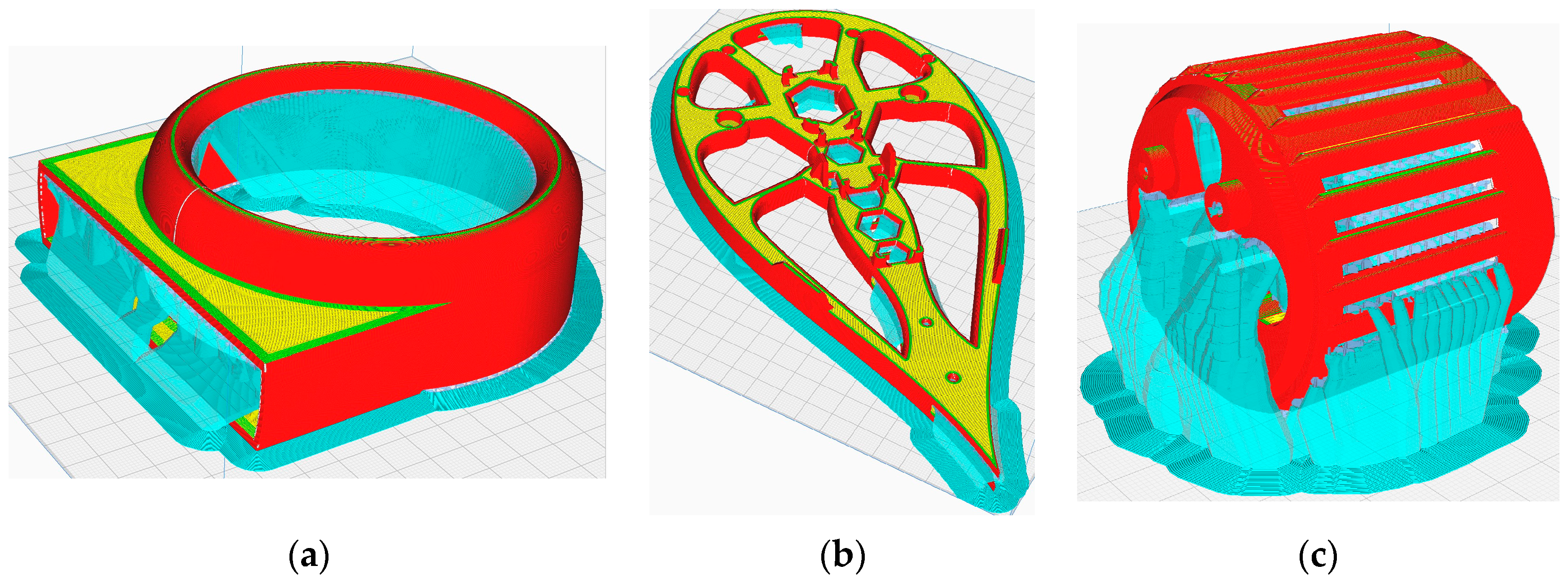
| Outside Air Multiplier Cilinder | 0.12 | 8 | 100 | 230 | 70 | Tree | Yes |
| Base Part | 0.12 | 3 | 15 | 230 | 70 | Tree | No |
| Motor Cage | 0.12 | 8 | 15 | 230 | 70 | Tree | No |
Disclaimer/Publisher’s Note: The statements, opinions and data contained in all publications are solely those of the individual author(s) and contributor(s) and not of MDPI and/or the editor(s). MDPI and/or the editor(s) disclaim responsibility for any injury to people or property resulting from any ideas, methods, instructions or products referred to in the content. |
© 2024 by the authors. Licensee MDPI, Basel, Switzerland. This article is an open access article distributed under the terms and conditions of the Creative Commons Attribution (CC BY) license (https://creativecommons.org/licenses/by/4.0/).
Share and Cite
Popișter, F.; Goia, H.Ș.; Ciudin, P.; Dragomir, D. Experimental Study of a 3D Printing Strategy for Polymer-Based Parts for Drone Equipment Using Bladeless Technology. Polymers 2024, 16, 533. https://doi.org/10.3390/polym16040533
Popișter F, Goia HȘ, Ciudin P, Dragomir D. Experimental Study of a 3D Printing Strategy for Polymer-Based Parts for Drone Equipment Using Bladeless Technology. Polymers. 2024; 16(4):533. https://doi.org/10.3390/polym16040533
Chicago/Turabian StylePopișter, Florin, Horea Ștefan Goia, Paul Ciudin, and Diana Dragomir. 2024. "Experimental Study of a 3D Printing Strategy for Polymer-Based Parts for Drone Equipment Using Bladeless Technology" Polymers 16, no. 4: 533. https://doi.org/10.3390/polym16040533
APA StylePopișter, F., Goia, H. Ș., Ciudin, P., & Dragomir, D. (2024). Experimental Study of a 3D Printing Strategy for Polymer-Based Parts for Drone Equipment Using Bladeless Technology. Polymers, 16(4), 533. https://doi.org/10.3390/polym16040533