Article

Full-Scale Experimental and Field Investigations into Expansion Mechanism of Foamed Polyurethane and its Lifting Behaviors for Repair and Maintenance of Railway Slab Track Systems

1
School of Civil Engineering, Southwest Jiaotong University, Chengdu 610031, China
2
Department of Civil Engineering, School of Engineering, University of Birmingham, Birmingham B15 2TT, UK
3
China Railway Construction Kunlun Investment Group Co., Ltd., Chengdu 610040, China
*
Author to whom correspondence should be addressed.
Polymers 2024, 16(3), 404; https://doi.org/10.3390/polym16030404
Submission received: 28 November 2023 / Revised: 29 January 2024 / Accepted: 30 January 2024 / Published: 31 January 2024

Abstract

:
Excessive settlement of the subgrade seriously reduces the service quality of slab tracks and threatens trains’ running safety. While the utilization of foamed polyurethane is recognized as an effective solution, previous research on its expansion mechanism and its impact on track lifting requires further refinement. Accordingly, a series of full-scale tests, including expansion force tests on foamed polyurethane with diverse qualities and lifting tests of polyurethane grouting with varied qualities on the track structure, have been conducted. The expansion development process of foamed polyurethane is meticulously elucidated, and key expansion parameters are analyzed. Simultaneously, this research explores the lifting behavior of foamed polyurethane grouting under the slab tracks, yielding new insights into essential lifting parameters for track formation repair and maintenance. Based on the experimental data, this study proposes new empirical formulas to comprehensively describe both the expansion mechanism of foam polyurethane and its lifting behavior under the slab tracks. The outcomes of this research offer a new breakthrough for the design of lifting mechanism for maintaining slab track structures through the utilization of foam polyurethane slurry grouting, such as determining the optimal grouting quantity. In addition, these results are instrumental to the evaluation of lifting effects and service life, enhancing the circular economy of railway track systems.

1. Introduction

As of the end of 2022, China’s high-speed railways span a total length of 42,000 km, as reported by the National Railway Administration of the People’s Republic of China. Nearly 70% of these railways are designed for the slab track, due to its notable stability and robust integrity. Illustrated in Figure 1a, the typical slab track system in high-speed railways (HSR) comprises the upper slab track plate, concrete base, and subgrade infrastructure, in which the surface layer and the bottom layer of the subgrade bed are filled with grade-broken stones and group A or B materials, respectively.
The stiffness of the track structure is much greater than that of the subgrade. This means that once the settlement occurs in the foundation, due to the stiffness difference, the track structure fails to undergo coordinated deformation with the subgrade. Consequently, as shown in Figure 1b, this weakens the contact between the track and subgrade, potentially leading to a loss of subgrade support, jeopardizing running safety, and causing damage to the track system. For instance, a simulating analysis [1] of the CRTS II slab track reveals that even a five millimeter subgrade settlement (with a settlement wavelength of 10 m) results in damage and a gradual loss of longitudinal tensile bearing capacity of the slab structure. Differential subgrade settlements contribute to track irregularities and deterioration [2,3,4,5], thereby adversely impacting the dynamic response of the track system during train operations. Various studies [6,7,8,9] suggest that as settlement amplitudes increase, dynamic wheel–rail interactions, car vibrations, and track structure vibrations intensify, posing threats to the comfort and safety of train operations.
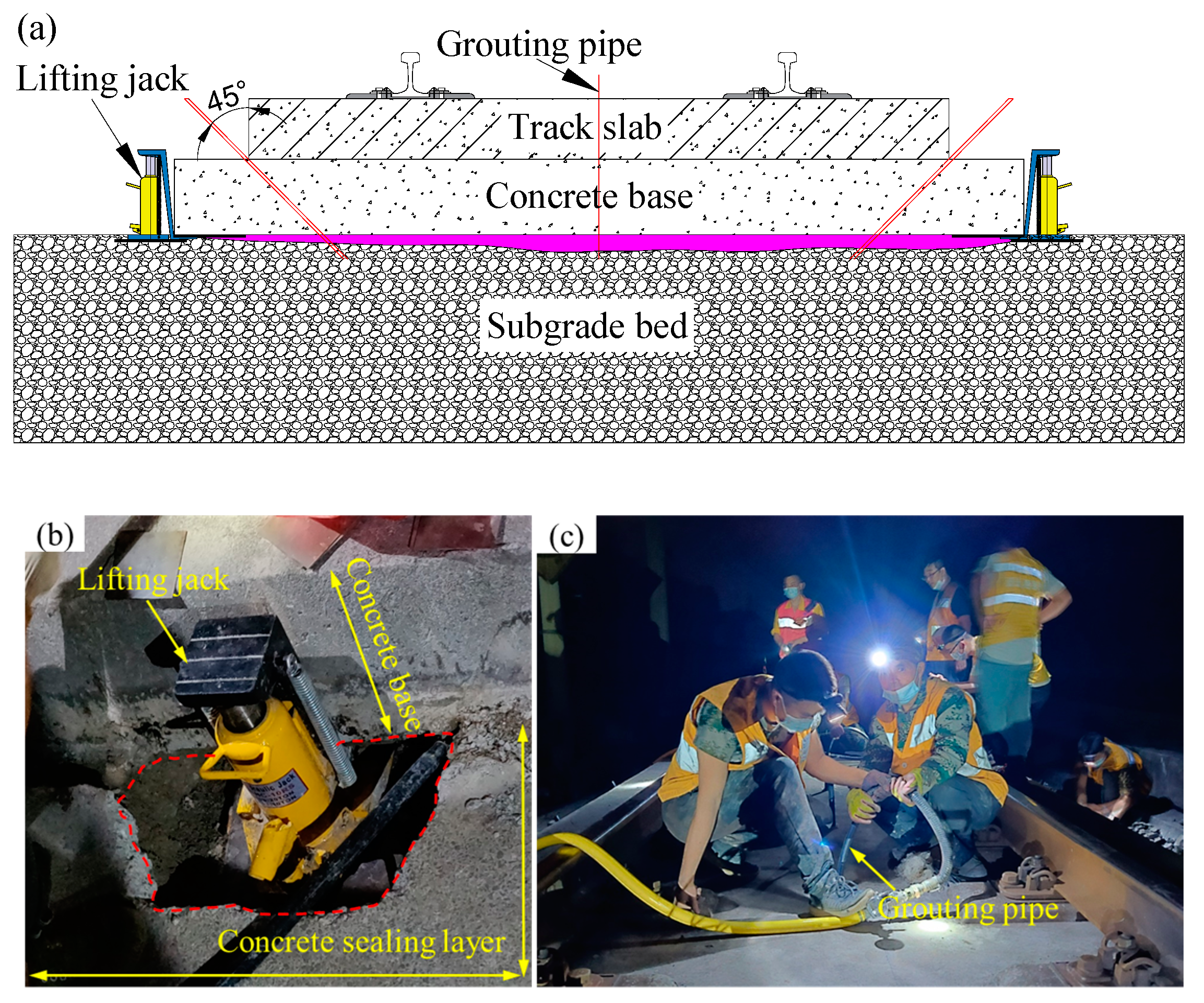
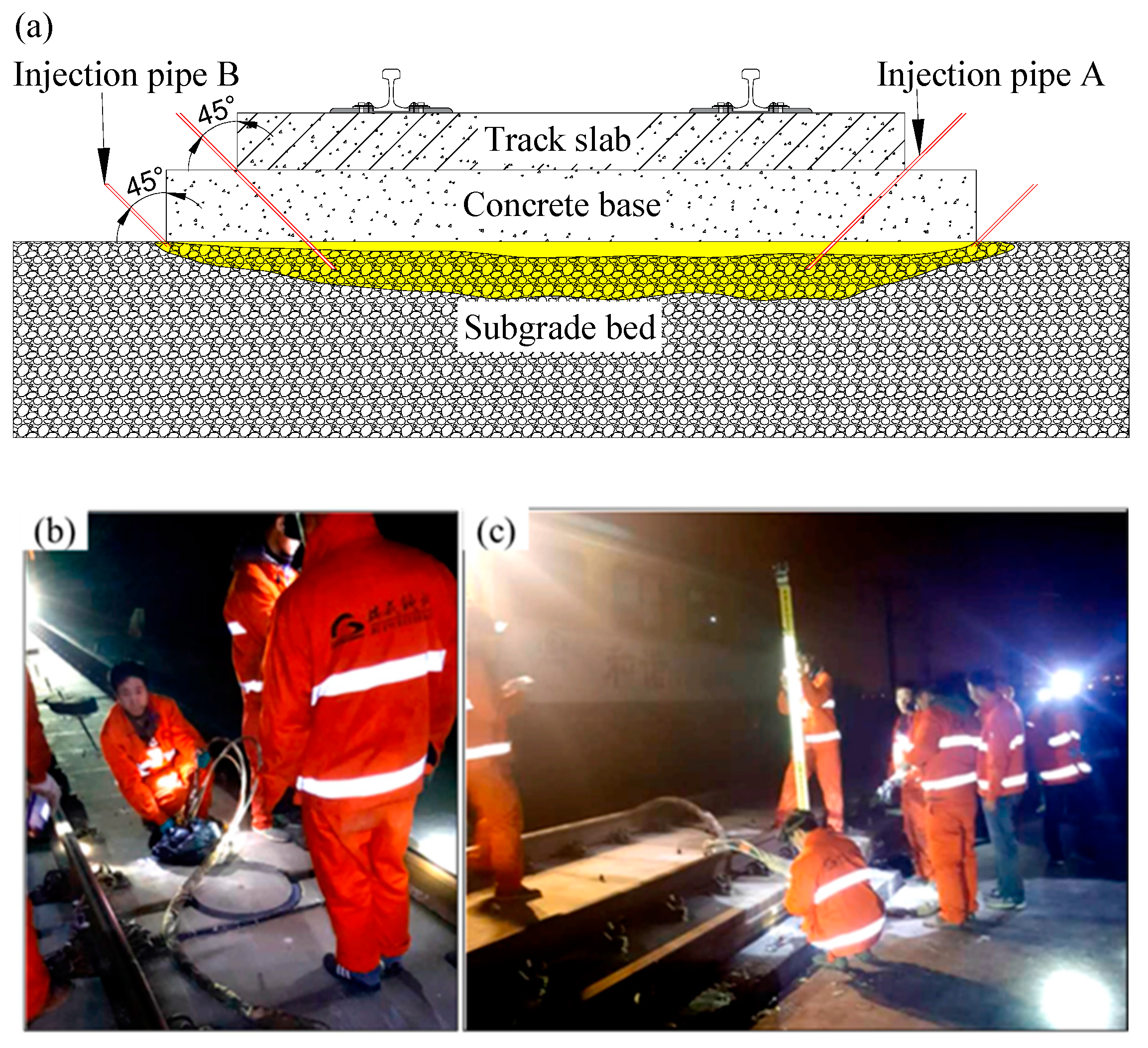
To ensure the smoothness and stability of slab tracks, China’s HSR design code [10] stipulates that post-construction settlement of the subgrade should not exceed 15 mm. Despite this, during the operation period of the HSR, factors such as groundwater [11,12] and mud pumping [13,14] still can induce uneven subgrade settlement, causing the strong vibration of the track structure under the train load, particularly in coastal and soft soil areas. To maintain the service amount, China’s HSR maintenance criteria [15] mandates that for lines with speeds exceeding 250 km/h, if the settlement wavelength ranges from 1.5 m to 42 m and the vertical settlement exceeds 8 mm in a specific area, repairs are required. Traditional methods involve adding height adjustment pads to the fastener system or lifting the track using jacks. However, it should be noted that the maximum adjustment height of the first method is no more than 26 mm according to the China’s HSR maintenance criteria [15]. As shown in Figure 2, the author’s research team successfully employed the latter traditional method to repair settlement lines in the Weituo-Jingkou Railway. However, this method can damage the integrity of the track system and the conduction process is complex. By contrast, as shown in Figure 3, lifting the slab track by grouting foamed polyurethane can minimize disturbance to the track structure and simplifies the repair process. The essence of this technology is that polyurethane slurry is grouted into a depth ranging from 0.10 m to 0.05 m of the subgrade bed, and then a polyurethane slurry undergoes a combination reactions and expansions, thus the slab structure is lifted. This means that the expansion mechanism of foamed polyurethane plays a crucial role in the effectiveness of this settlement repair method.
Mixing components such as isocyanates, polyols, catalysts, chain extenders, and crosslinkers in specific mass ratios enables the rapid synthesis of polyurethane. This material has excellent properties [16], including high porosity, is lightweight, and has a superior anti-deformation capacity. Many research results [17,18,19,20,21,22,23,24] find that this material has perfect mechanical properties, and laboratory tests and numerical analyses reveal the material’s effectiveness in improving the mechanical properties of sand [25], expansive soil [26], loess soil [27], and gravels [28]. Numerous studies [14,29,30,31,32,33,34,35] demonstrate that by adjusting the mix ratio and density, polyurethane proves beneficial in maintaining the performance of railway foundations. Applications include treating mud pumping, strengthening sleepers and subgrade beds, and solidifying ballasted tracks. These findings indicate that controlling the mix ratio and density ensures that polyurethane meets the compressive strength, tensile strength, and dynamic strength requirements outlined in the HSR design code. This implies that polyurethane layers or mixed gravel layers can effectively support track structures. Additionally, a full-scale model [36] and in-site tests [37] have proven the effectiveness of lifting the track structure by grouting a foamed polyurethane slurry. Moreover, long-term dynamic loading tests have shown that the dynamic response of the slab track has been improved after grouting. However, the concealment and randomness of polyurethane grouting in the interlayer between the concrete base and subgrade bed present challenges to the application of this technology. Moreover, the relationship between the grouting parameters, including grouting quantity, grouting duration, and lifting displacement, remains unclear. Polyurethane grouting for slab track lifting presently relies on experience and real-time observation.
In this paper, a series of expanding force tests is constructed to explore the expansion mechanism with different quantities of the foamed polyurethane. Subsequently, a full-scale slab track model is established, and foamed polyurethane grouting is performed. Based on testing data, the lifting mechanism of polyurethane with different grouting quantities on the slab track is discussed. Empirical formulas are proposed to describe the expansion process of the foamed polyurethane and lifting process by foamed polyurethane grouting on the slab track. The research findings presented in this paper serve as valuable references for the design and assessment of lifting slab tracks employing polyurethane grouting techniques. The insights will improve lifecycle asset management and circular economy practices of high-speed railway track systems.

2. Expansion Properties of Polyurethane

2.1. Preparation of Polyurethane and Testing Procedure

The foamed polyurethane utilized for lifting the slab track was synthesized with two component slurries in a certain proportion. Generally, component A was isocyanate, while component B comprised a mixture of polyether polyol and various additives, including a catalyst, chain extension crosslinking agent, foaming agent, and foam stabilizer. In this study, the types and physical properties of selected isocyanates and polyether polyol are shown in Table 1a. The catalyst, chain extension crosslinking agent, and foam stabilizers employed were triethylenediamine (TEDA), butane-1,4-diol (BDO), and polyether-modified polysiloxane (PMP), respectively. The physical properties of these different additives provided by the manufacturers are summarized in Table 1b,c. Notably, water was chosen as the foaming agent. The synthesis ratio of foamed polyurethane was mPAPI:mMDI4110:mPOP2140:mTEDA:mBDO:mPMP:mw = 50:50:200:22.5:2.5:10:4, as set in this research.
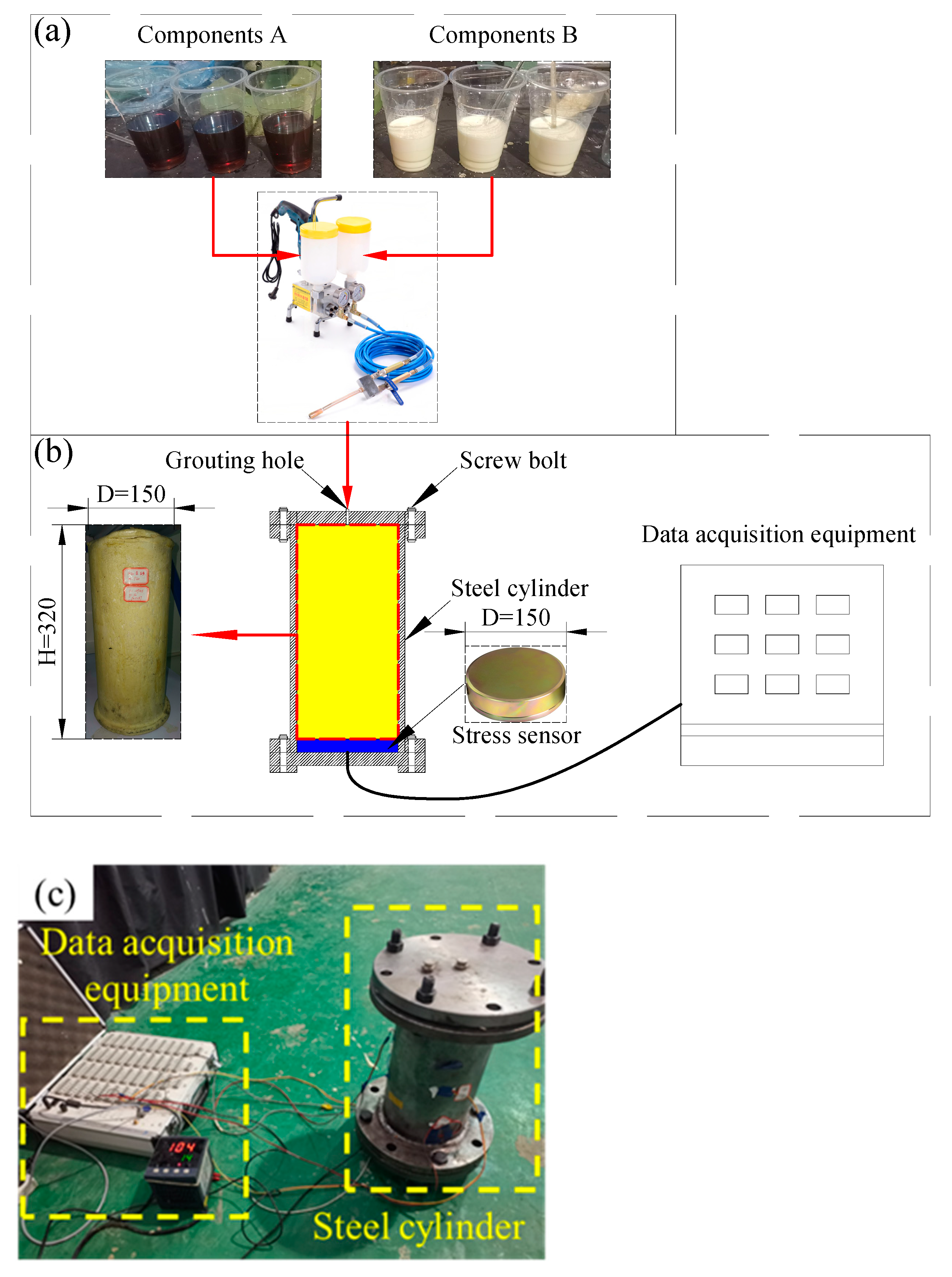
The foamed polyurethane preparation process is depicted in Figure 4a. Firstly, component A and component B slurries were prepared according to the designated mix ratio and injected into separate barrels, respectively. Subsequently, using the grouting pump, component A and component B were uniformly mixed and rapidly grouted into the steel cylinder. Once both slurry types were completely injected into the steel cylinder, the grouting hole was sealed, and data of grouting durations and expansion force collections commenced. Notably, the steel cylinder, with an inner diameter of 15 cm, a net height of 32 cm, and a wall thickness of 2 cm, had its top and bottom sealed by flanges, setting the stress sensor on the top surface of the bottom flange. The test equipment is shown in Figure 4a,b. Ten different densities were designed: 0.110 g/cm3, 0.140 g/cm3, 0.190 g/cm3, 0.210 g/cm3, 0.250 g/cm3, 0.300 g/cm3, 0.350 g/cm3, 0.400 g/cm3, 0.450 g/cm3, and 0.530 g/cm3, corresponding to grouting foamed polyurethane quantities of 622.0 g, 791.7 g, 1074.4 g, 1187.5 g, 1413.7 g, 1696.5 g, 1979.2 g, 2261.9 g, 2544.7 g, and 2997.1 g, respectively.

2.2. Testing Results

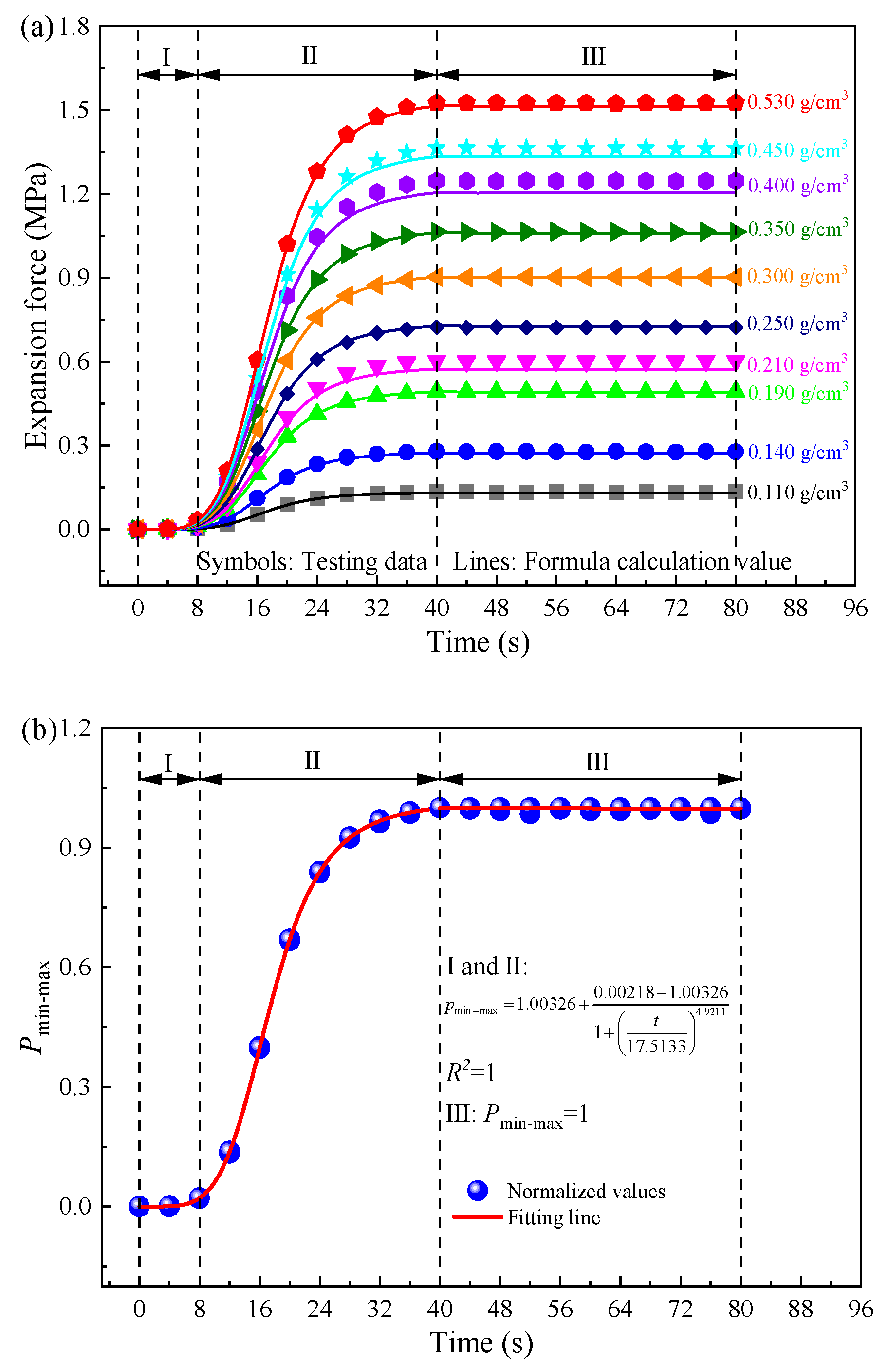
Expansion time history curves of foamed polyurethane with different densities are depicted in Figure 5a. Remarkably, although the final expansion pressure value increased with density, the expansion development process of foamed polyurethane remained consistent. Thus, the Min-Max normalization method was used to eliminate the influence of numerical values and discuss the expansion mechanism of foamed polyurethane. Specifically, the normalization values can be calculated using the following equation:
p = p i p min p max p min ,
where p′ represents the normalized value of the foamed polyurethane expansion force, pi is the testing value of the foamed polyurethane expansion pressure at any time for a specific density, and pmax and pmin denote the maximum and the minimum values of the expansion pressures of foamed polyurethane for that density. The normalized results of foamed polyurethane expansion pressures are plotted in Figure 5b.
Before delving into the expansion mechanism of foamed polyurethane, it is essential to understand the chemical foaming reaction principle underlying foamed polyurethane. In this study, foamed polyurethane was synthesized using the One-Step Method, wherein the polycondensation reaction between isocyanates and polyols, alongside the bubble production reaction between isocyanates and water, occurs concurrently. Facilitated by catalysts and chain extenders, the polycondensation reaction forms polyurethane chains [38,39]. Simultaneously, with the aid of bubble stabilizers, isocyanates react with water, generating CO2 [38,39], which is uniformly dispersed among the polyurethane chains. Upon completion of the reaction, polyurethane with porous characteristics is formed. Notably, the process of bubble formation corresponds to the development of the expansion pressure. The typical chemical reaction formula for this method is as follows:
R N C O + H O R + H 2 O = R N H C O O R + C O 2 ,
Continuing the analysis of the foamed polyurethane expansion mechanism based on Figure 5a,b, it is evident that the expansion process unfolds in three distinct stages. In stage I, expansion pressure is not generated until 8 s, which means the bubble production reaction does not occur until the time comes to 8 s. Consequently, stage I is deemed the initial reaction stage, with the initial reaction time being 8 s. Then, it transitions into stage II, characterized by the rapid growth of the expansion pressure. Specifically, from 8 s to 32 s, the expansion pressure rapidly increases, while the increase rate slows down after 32 s. When the time comes to 40 s, the expansion pressure reaches the maximum value, which is also the final expansion pressure. This also indicates that the bubble production reaction mainly occurs during the 8–40 s time period. Furthermore, in this stage, the growth rate of the expansion pressure exhibits an escalating trend with increasing density (or grouting quantity). Specifically, within the density range of 0.110 g/cm3 to 0.250 g/cm3, growth rates range from 0.0041 MPa/s to 0.0222 MPa/s. For foamed polyurethane with densities ranging from 0.030 g/cm3 to 0.350 g/cm3 and 0.400 g/cm3 to 0.530 g/cm3, the corresponding increase rates range from 0.0276 MPa/s to 0.0326 MPa/s and 0.0381 MPa/s to 0.0467 MPa/s, respectively. In addition, the higher the density of foamed polyurethane, which means a greater grouting quantity, the greater its final expansion pressure. Finally, after 40 s, it is in stage III, the solidifying stage. In this stage, expansion pressures fluctuate around the maximum values of the expansion pressure (also the final expansion pressure) before stabilizing. This suggests that foamed polyurethane does not undergo shrinkage during the solidification stage, enhancing its stability for use in the subgrade bed supporting the slab track. Remarkably, the expansion duration (tr) is consistently 40 s, regardless of the foamed polyurethane slurry quantity.
Expanding on the prior analysis, it is discerned that stages I and II collectively represent the entire expansion process of foamed polyurethane, resembling the curve of the Logistic function. Stage III is identified as the stable stage. Mathematical formulations can be postulated to articulate this developmental pattern, as delineated below:
f ( t ) = p f + p s p f 1 + t t 0 μ 1   ( 0 t t f ) ,
f ( t ) = p f   ( t > t f ) ,
where pf and ps (MPa) signify the final values and initial values of the expansion pressures of foamed polyurethane with a certain density, respectively. In this study, ps is 0. The coefficient t denotes time (s), tf represents the time point at which expansion ends, while t0 and μ1 represent the inflection point of the curve and slope at the inflection point, respectively. This means that t0 is the critical time point at which the bubble production reaction transitions from intense to slow, and μ1 is associated with the bubble production reaction rate at this juncture. Actually, the bubble production reaction is linked to the raw material ratio of the synthesized foamed polyurethane, independent of the quantity of foam polyurethane slurry. Moreover, all data in Figure 5a are normalized by the Min-Max normalization method and plotted in Figure 5b, where it can be found that the expansion process exhibits similarity regardless of the foamed polyurethane slurry quantity. Therefore, through fitting from Figure 5b, the values of t0 and μ1 are determined to be 17.5133 and 4.9211, respectively.
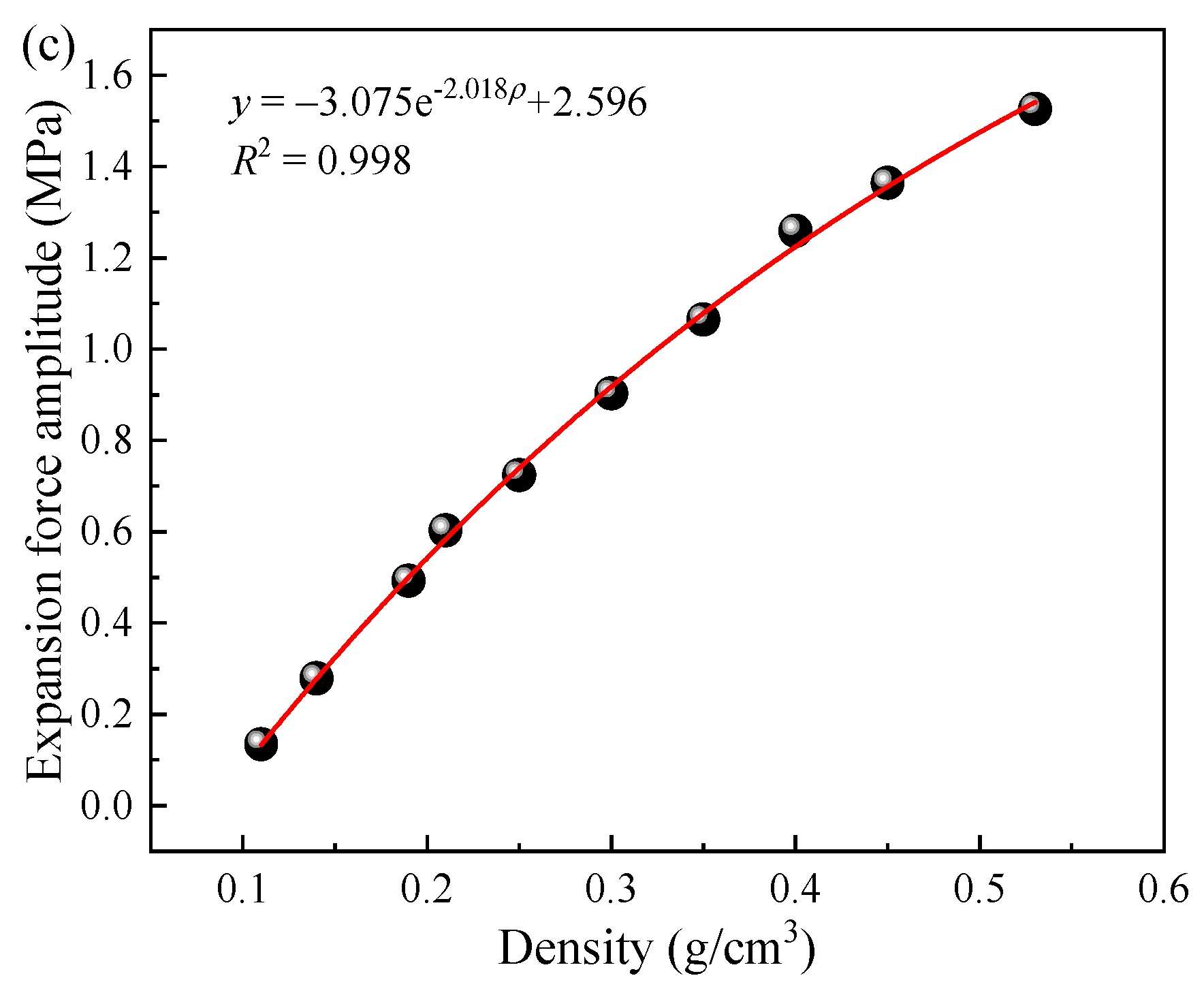
As mentioned previously, the expansion pressure exhibits an increase with the rise in the density of cured foamed polyurethane. Drawing from testing data, Figure 5c is formulated to explore this relationship. Through calculation, this can be articulated using a natural exponential function, expressed as:
p f = a e b ρ + c ,
where pf signifies the final expansion pressure values (MPa), ρ represents the density of foamed polyurethane (g/cm3), and a, b, and c all denote correlation coefficients. Following fitting with the testing data, the coefficients are determined as −3.075, −2.018, and 2.596, respectively. Furthermore, considering that ρ is the mass-to-volume ratio, with a known volume, the final expansion pressure can be calculated based on the grouting quantity using the following equation:
p f = a e b m V + c ,
where m represents the quantity of polyurethane slurry (g) and V is the volume (cm3). Thus, combining Equations (3)–(6), the empirical mathematical expression of the expansion mechanism of foamed polyurethane is proposed as follows:
f ( t ) = ( 3.075 e 2.018 m V + 2.596 ) t 4.9211 17.513 3 4.9211 + t 4.9211   ( 0 t t r ) ,
f ( t ) = 3.075 e 2.018 m V + 2.596   ( t > t r ) ,
where t represents any time point during the experimental process (s), ρ represents the density of foamed polyurethane (g/cm3), and f(t) denotes the expansion pressure at any time (Mpa). In this study, tr is 40 s. Therefore, the calculation results of expansion pressures of foamed polyurethane of different quantities can be obtained and plotted in Figure 5a. Obviously, the calculated values closely align with the testing data, with related errors consistently below 7.10%. It is emphasized that while errors in the initial stage might appear slightly larger, given the minute values of expansion pressures, these discrepancies are negligible. Thus, the expansion process of polyurethane foam in a completely confined space can be described using Equations (7) and (8).

3. Lifting Behaviors by Polyurethane Grouting to the Slab Track

3.1. Model Construction and Testing Procedure

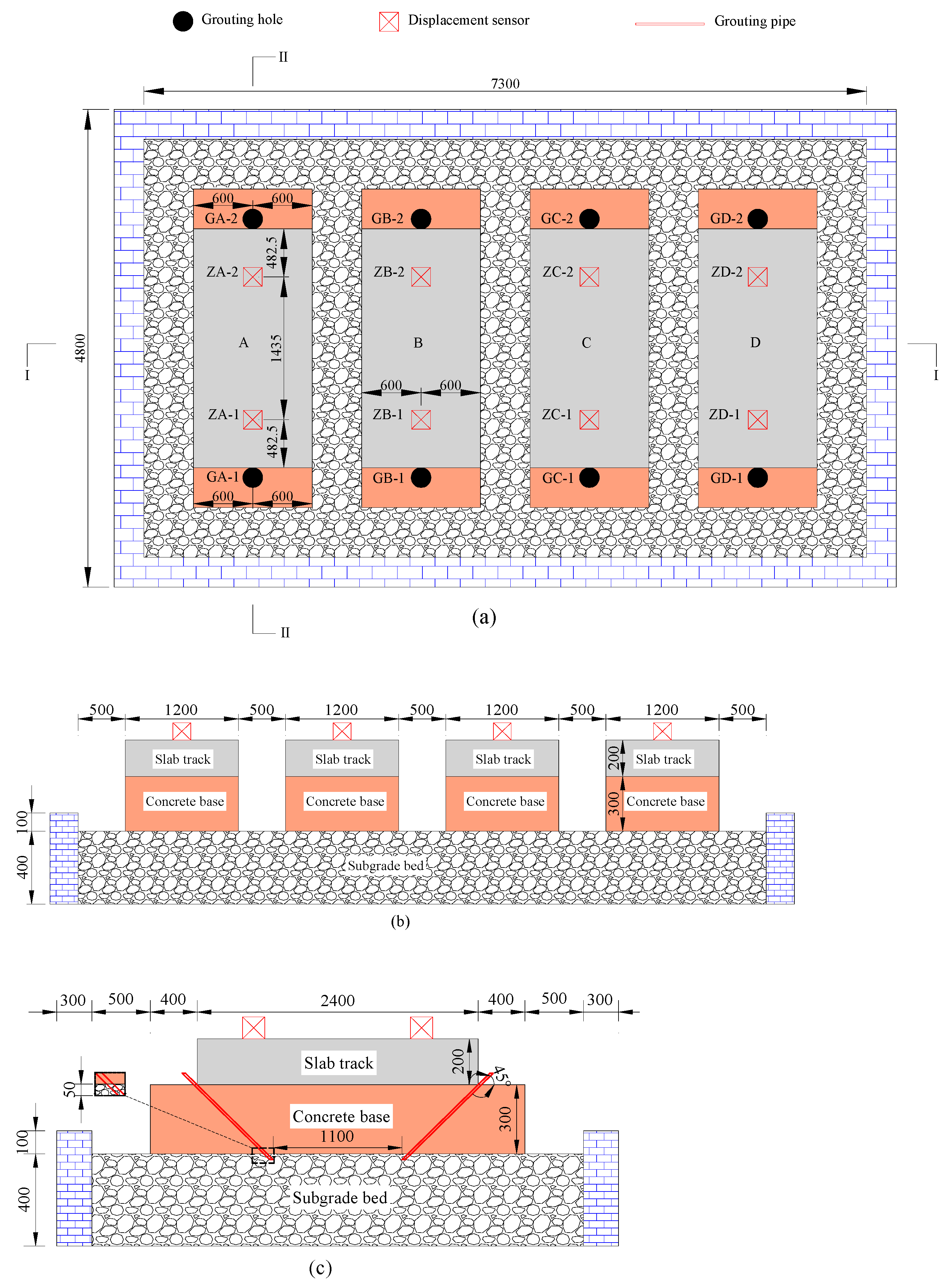
The full-scale slab track grouting model was constructed in a brick wall box measuring 7.3 m in length, 4.2 m in width, and 0.5 m in height, as illustrated in Figure 6. This model comprised slab tracks, concrete bases, and a subgrade bed filled with well-graded gravel, all constructed following the Chinese high-speed railway design code [10]. It is noteworthy that the slab track was built with concrete (C50) and threaded steel bars with a diameter of 20 mm, and the concrete base plate was built with concrete (C15). In this study, four track structures with a length of 1.2 m were constructed for lifting tests of different grouting quantities. The construction process is detailed in Figure 7. The compaction degree of the subgrade bed was set to 0.97.
The track structure was cast in place directly on the surface of the subgrade bed, as illustrated in Figure 7a. Following concrete paving and vibration (as shown in Figure 7b,c), the surface of the slab track was covered with PE film for a curing period of 7 days. Subsequently, grouting holes with a diameter of 25 mm were drilled in each slab track structure, as shown in Figure 7d. Grouting pipes with a diameter of 25 mm were then inserted into all the holes, with the end of the grouting pipe positioned approximately 5 cm below the surface of the subgrade bed, as illustrated in Figure 6c. Displacement sensors were installed on the surface of each slab track structure, and the distribution of the grouting holes and displacement sensors is plotted in Figure 6a–c.
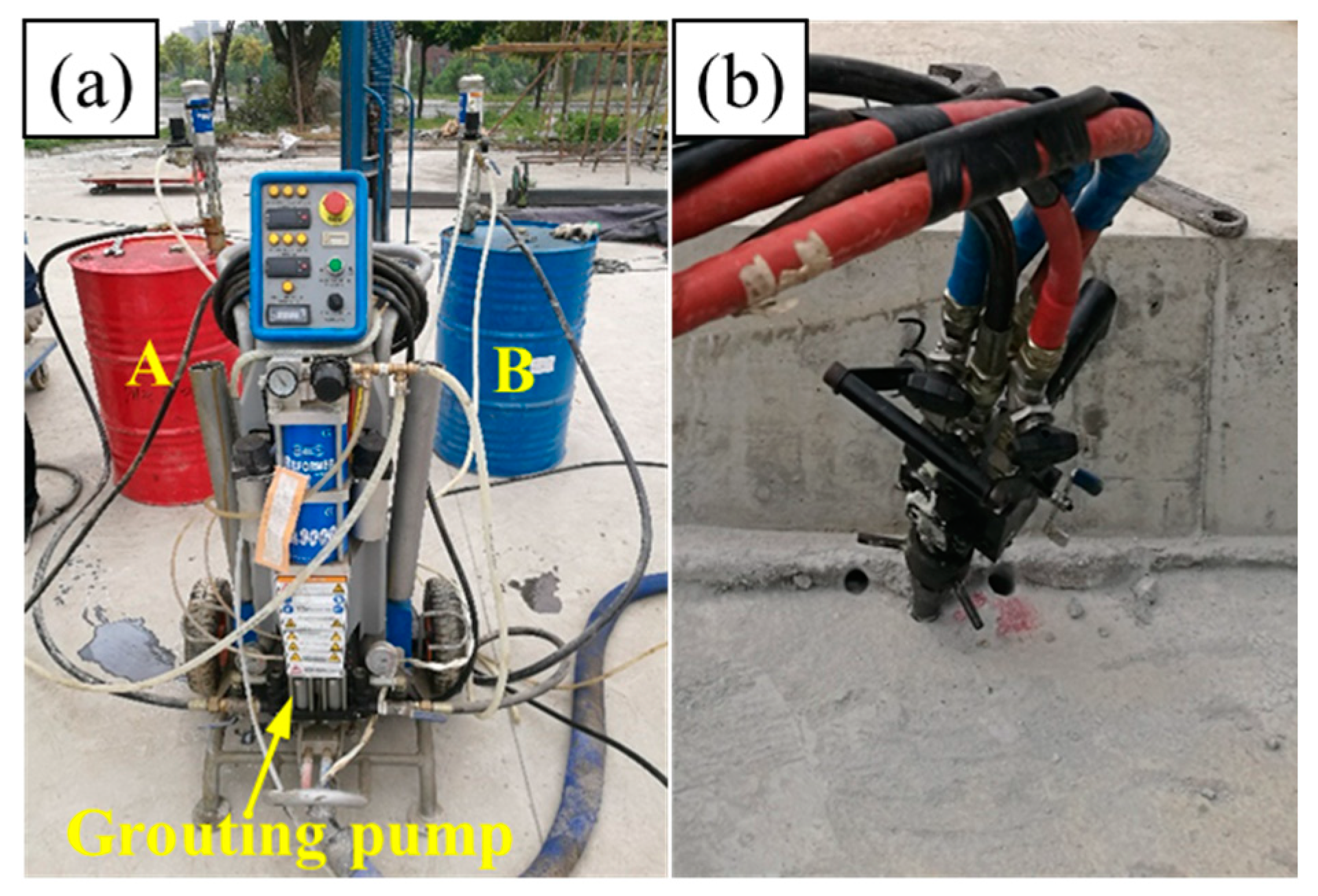
In this study, the total quantity of foamed polyurethane grouted into the slab track structures A, B, C, and D were 3.0 kg, 4.5 kg, 6.0 kg, and 7.5 kg, respectively. For structures A, B, C, and D, the grouting quantity in a single hole was 1.50 kg, 2.25 kg, 3.00 kg, and 3.75 kg, respectively. Synchronous grouting on both sides of the slab track was conducted to ensure balance during the lifting process. Specifically, as shown in Figure 8, the components A and B were first prepared in sufficient quantities following the synthesis ratio mentioned earlier. Subsequently, these components were simultaneously grouted into the subgrade bed through the holes on both sides of the slab track using a grouting pump. The grouting pressure was set to 5 MPa, and once the set grouting quantity was reached, the grouting was stopped. Data collection commenced from the beginning of the grouting process, with a data collection interval set to 1 s. When the displacement tended to stabilize, data collection was stopped.

3.2. Testing Results and Discussion

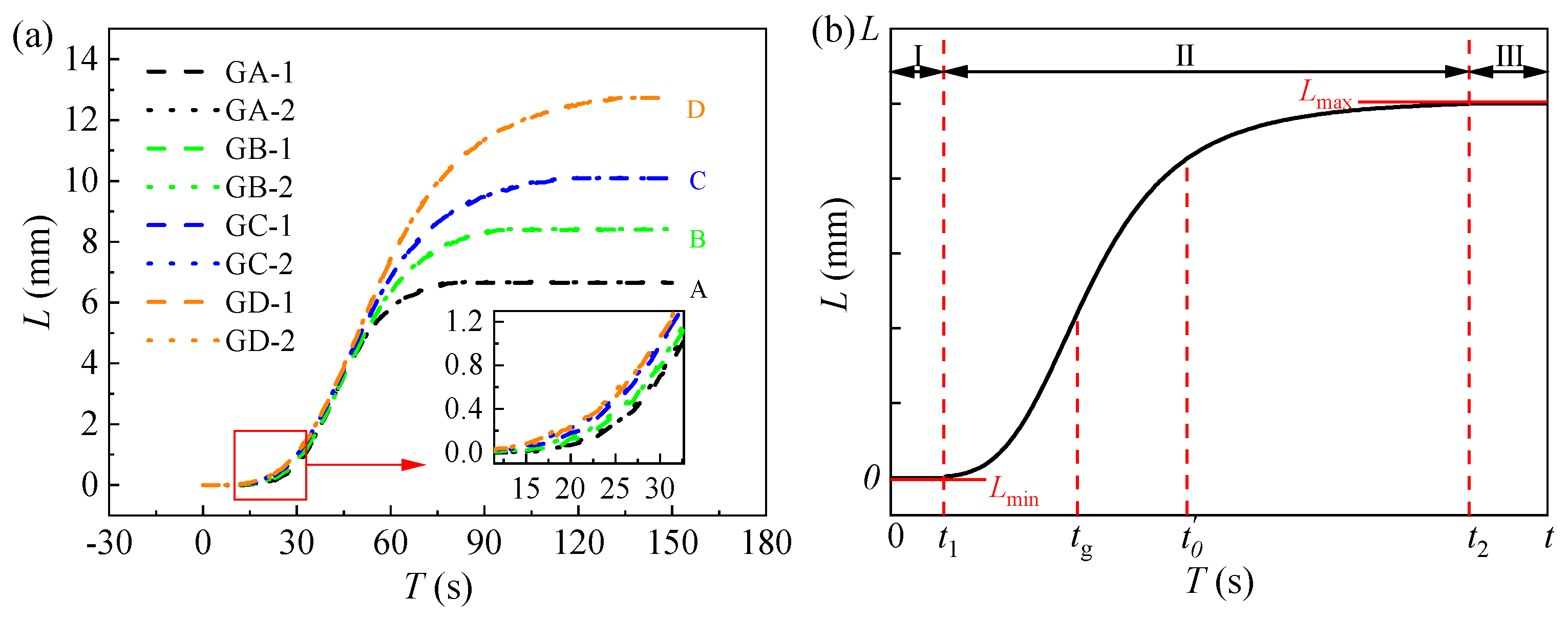
The variation in the laws of lifting displacement with time history for each testing point are plotted in Figure 9. It is obvious that the related errors of the test values for lifting displacement at different measuring points of the same structure are very small. Specifically, the related errors between the testing values at GA-1 and GA-2, at GB-1 and GB-2, GC-1 and GC-2, and GD-1 and GD-2 are all less than 2.00%. This observation illustrates the efficacy of symmetrical synchronous grouting on both sides in ensuring uniform lifting of the slab track structure. Furthermore, it can be found that the increase laws with time are similar, although the lifting displacement amplitudes (the final lifting displacement values) are different. This phenomenon is illustrated by Figure 9b.
The lifting mechanism of the grouting foamed polyurethane can be divided into three stages. Stage I ranges from the grouting start to t1 and is the diffusion and initialization reaction stage. In this stage, the foamed polyurethane slurry gradually diffuses in the subgrade bed under the influence of grouting pressure. Once reaching the critical point of the combination reaction, the slurry gradually solidifies and expands. As mentioned before, the expansion pressure increases with time; thus, lifting only occurs when the expansion pressure reaches the self-weight of the track structure, i.e., at time t1. During stage I, the lifting displacement is the smallest (Lmin), with a value of 0. It then enters stage II, the lifting stage, where the grouting continues, and the slurry undergoes combination reactions and foaming, resulting in a rapid increase in the expansion pressure and lifting of the slab track until the grouting stops at the moment of tg. After that, the slurry gradually stops diffusing but continues to undergo a combination reaction, thereby continuing to rapidly lift the slab track. Subsequently, in the time period t0 to t2, the combination reaction and foaming of the slurry gradually slow down, the foamed polyurethane slurry solidifies gradually, and the lifting displacement increases slightly. At t2, the combination reaction and foaming of the foamed polyurethane are completed, lifting stops, and the lifting displacements reach the maximum values (Lmax), which are also the final lifting displacement values (Lf). t2 marks the end time of lifting. Finally, stage III is entered, where the lifting displacement fluctuates around the values of Lf in the initial period and then tends to stabilize at Lf gradually. The track structure is supported by the cured polyurethane and the subgrade bed.
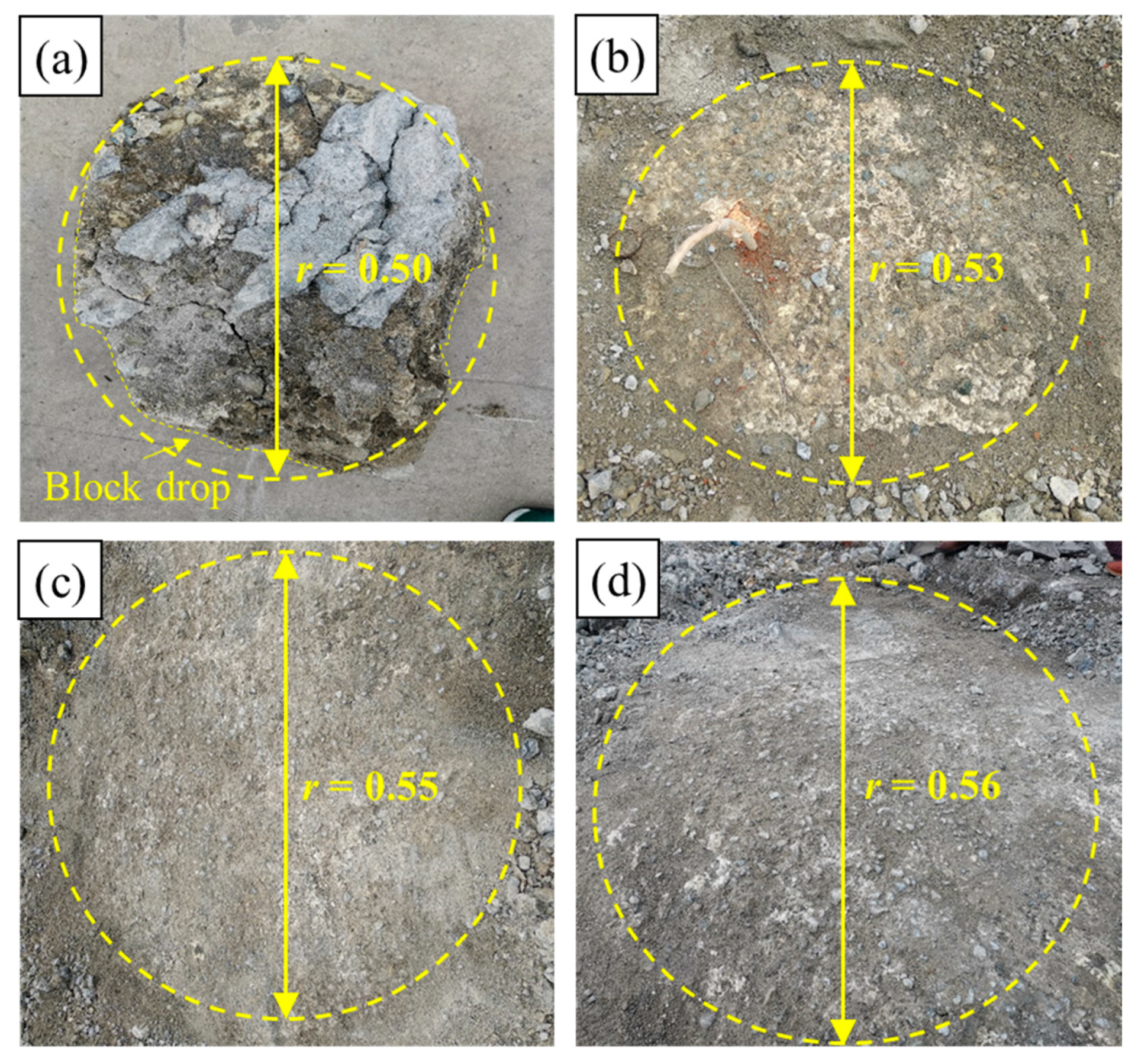
After 2 h of completing the lifting, the slab track structure was removed, and the diffusion radius under different grouting quantities can be observed, as shown in Figure 10. Notably, the diffusion area of foamed polyurethane grouting in the well-graded gravel resembles a circular shape, although some solid blocks within the diffusion area have detached. The key values from the grouting tests, including total grouting quantity (mt), grouting duration (tg), final lifting displacements (Lf), diffusion radius (r), initial lifting time (t1), and lifting duration (t2), were obtained and are presented in Table 2. The data illustrates that, under consistent grouting pressure and medium, the final lifting displacements are positively correlated with the total grouting quantity. Moreover, due to the time-dependent viscosity of the foamed polyurethane slurry, and the friction resistance of the well-graded gravel, an increase in grouting quantity leads to a prolonged grouting duration, assuming the grouting pressure remains constant. In the same grouting environment, the initiation time for lifting, with different total grouting quantities, is nearly identical, emphasizing that the initial reaction time of foamed polyurethane is primarily linked to its composition. Furthermore, the observed end times for lifting exceed the theoretical values, which account for the sum of the grouting duration and foamed polyurethane synthesis reaction duration (in the steel cylinder). This suggests that the combination reaction of foamed polyurethane slurry in well-graded gravel with a certain compaction degree is considerably more intricate than that in the steel cylinder.
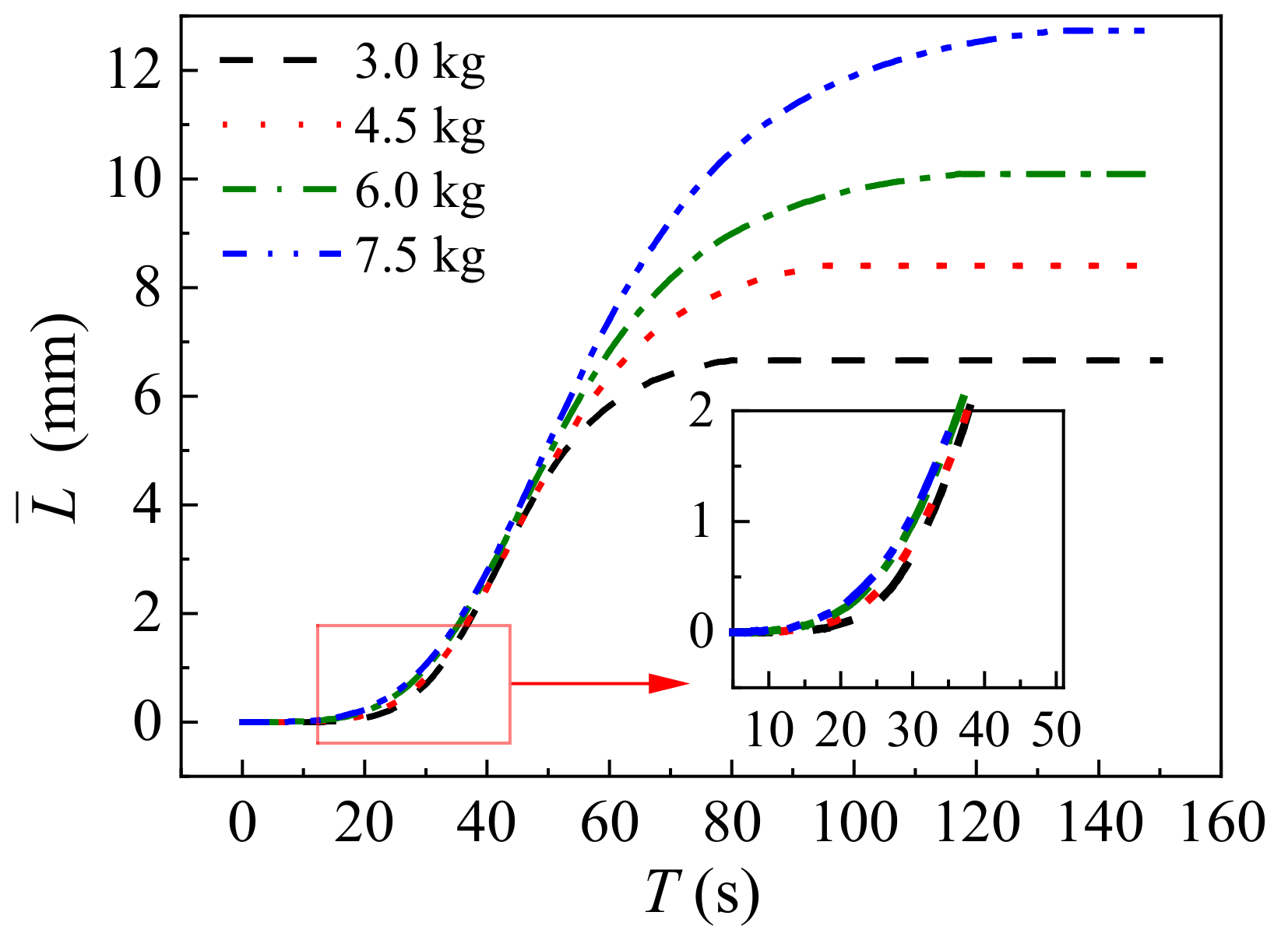
As previously mentioned, the error between the lifting values on both sides (A, B, C, and D) is minimal. Consequently, the average values ( L ¯ ) can be calculated using the following equation to further discuss the lifting mechanism:
L ¯ = L 1 i + L 2 i 2 ,
where L 1 i and L 2 i (mm) represent the testing values of the lifting displacement on both sides of the track slab at any time. The resulting curve of L ¯ T is plotted in Figure 11. Additionally, the non-linear relationship between the lifting displacement and time is attributed to the expansion mechanism of foamed polyurethane. It is observed that both stages I and II in all time history curves of lifting displacement resemble the curve of the logistic function, and in stage III, the lifting displacement stabilizes at Lf. Hence, the following mathematical formulas can be given out to describe the lifting behavior of foamed polyurethane grouting:
f ( t ) = L max + L min L max 1 + ( t t 0 ) μ 2   ( 0 t t 2 ) ,
f ( t ) = L max   ( t 2 < t ) ,
where t represents time (s), and t0 and μ2 denote the inflection point and slope at the inflection point during the growth stage of the curve, respectively. In this study, Lmin is 0, and Lmax is related to the total grouting quantity, as mentioned before. Values of t’0 and μ2 can be obtained by fitting the data in Figure 11, and are plotted in Table 3.
Based on previous analysis, it is apparent that the expansion pressure is closely linked to the quantity of foamed polyurethane, and considering that the self-weight of the track structure plays a critical role in the lifting process, the ratio of grouting quantity to the self-weight of the track structure is introduced to evaluate the final lifting displacement value. Additionally, it is observed that values of t0 are greater than those of tg in all curves. In stage II, during the period from t1 to tg, the slurry expands while diffusing, and when the grouting is completed, that is, after tg, the slurry still diffuses for a short period, while the diffusion of the slurry affects the foaming of the slurry. As mentioned previously, t0 is the inflection point. Based on these analyses, it can be proposed that t0 correlates with m and tg. It is evident that the duration of lifting is closely associated with both the grouting and expansion durations of foamed polyurethane. Building on the aforementioned analyses, the following equations are proposed to discuss the parameters in Equation (5):
L f = a 1 m t M b 1 ,
t 0 t g = a 2 m b 2 ,
μ 2 = a 3 m b 3 ,
t 2 = a 4 t g + t r b 4 ,
where m and M (kg) signify the foamed polyurethane grouting quantity in a single hole and the self-weight of the slab track, respectively. tr denotes the duration of foamed polyurethane expansion, while ai and bi represent correlation coefficients. In this study, M is 4320 kg and tr is 40 s. Therefore, the utilization of Equations (12)–(15) allows the generation of Figure 12, illustrating the values of all coefficients, as depicted in the figure. Specifically, in this investigation, a1 and b1 are 1259.96 and 0.7271, respectively. Similarly, a2 and b2 are found to be 3.6172 and −0.9449, respectively, while a3 and b3 are 6.5119 and −0.3985, and a4 and b4 are 0.9273 and 1.0970, respectively. All R-Square values exceed 0.95, indicating the reliability of the coefficients obtained through fitting testing data.
In the grouting process, the monitoring values of tg are crucial for evaluating the lifting effect. When the grouting environment remains unchanged, the grouting duration can be estimated based on the grouting quantity. In this study, through calculations, as depicted in Figure 13a, it was observed that the relationship between tg and m can be expressed by the following equation:
t g = a 5 m b 5 ,
where a5 and b5 are coefficients, determined to be 10.1142 and 1.3064, respectively, in this study. Utilizing Equation (16), the calculated values of tg for grouting quantities of 1.50 kg, 2.25 kg, 3.00 kg, and 3.75 kg are 17 s, 29 s, 42 s, and 57 s, respectively. The related errors between the calculated and testing values of tg are −5.56%, 0, 2.44%, and 7.55%, respectively, confirming the reliability of Equation (16). Consequently, values of Lf, t0, μ2, and t2 can be determined by combining Equation (12) through Equation (16). The calculated values (CALC) and testing values of these parameters are presented in Table 3. The absolute related errors between the test values and calculated values for all parameters range from 0 to 5.66%, demonstrating the reliability of the calculated values. Employing Equations (4)–(16), the time history curve of the lifting displacement with different grouting quantities can be plotted in Figure 13b. It is evident that for structures A, B, C, and D, the maximum related errors between the calculated values and testing values of the lifting displacement are −7.00%, −2.42%, 0.61%, and 6.76%, respectively. This indicates an acceptable level of accuracy; therefore, Equations (5)–(16) are recommended for estimating the quantity of foamed polyurethane grouting required to lift the track slab and for evaluating the real-time lifting development process.

4. Conclusions

This paper conducts a thorough examination of the expansion force characteristics of foamed polyurethane and explores the lifting behavior of the foamed polyurethane on slab tracks through grouting lift tests. The following conclusions can be drawn.
(1) The initial reaction time and expansion duration of the foamed polyurethane slurry remain at 8 s and 40 s, respectively. The final expansion pressure and growth rate are positively correlated with the grouting quantity, and an empirical formula is provided to calculate the final expansion pressure based on the grouting quantity.
(2) The expansion process of the polyurethane slurry is categorized into three stages: the initial reaction stage, expansion development stage, and the stable stage. The initial reaction and expansion development stages are described using logical functions, while the stable stage is represented as a constant function. The boundary time point between the expansion development stage and the constant stage is determined as T = 40 s.
(3) The diffusion morphology of the foamed polyurethane slurry in the shallow layer of the subgrade bed surface appears circular. Under constant grouting pressure, the diffusion radius in well-graded gravel with a compaction degree of 0.97 increases non-linearly with the grouting quantity. The starting time of lifting is less affected by the quantity of grouting, while the duration of lifting is related to the grouting quantity and duration. The final lifting displacement value shows an increasing trend with the rise in grouting quantity.
(4) The lifting process exhibits characteristics resembling the approximation curve and can be divided into three stages: the diffusion of the slurry and the initial reaction stage, the continuous lifting stage, and the slurry solidification forming stage, which also is the stable lifting stage. The optimized logical function formula has been proposed to describe the process of uplift development, and a constant function can be used to express the stable stage of uplift. In addition, empirical formulas have been proposed to determine the grouting duration and lifting duration based on the grouting quantity. The insights obtained from this study have already been applied to high-speed railway track maintenance practices in reality. The outcome helps high-speed rail engineers improve lifecycle asset management and circular economy practices in the railway industry.
While this study offers valuable insights into the application of foamed polyurethane for the settlement repair of slab tracks, it acknowledges certain limitations, such as the incomplete explanation of the foamed polyurethane slurry diffusion mode in well-graded gravel, and the influence of spatial constraints conditions on the expansion mechanism of foamed polyurethane. These scientific questions will be addressed in future numerical and theoretical analyses to optimize and refine the inflation mechanism and uplift mode proposed in this paper.

Author Contributions

Conceptualization, Z.H., Q.S., X.W. and S.K.; methodology, Z.H., Q.S., J.H. and S.K.; software, Q.S.; validation, Z.H., Q.S., T.L., J.H., X.W. and S.K.; formal analysis, Z.H., T.L., J.H. and S.K.; investigation, Z.H., Q.S., T.L., J.H., X.W. and S.K.; resources, Q.S., T.L., J.H. and S.K.; data curation, Q.S.; writing—original draft, Z.H. and Q.S.; writing—review and editing, Z.H., Q.S., T.L., J.H., X.W. and S.K.; visualization, Z.H., X.W. and S.K.; supervision, S.K.; project administration, S.K.; funding acquisition, S.K. All authors have read and agreed to the published version of the manuscript.

Funding

This research was funded by the China Scholarship Council National (No. 202107000077), the Natural Science Foundation of China (Grant No. 51978588 and Grant No. 52078434), the Technology Research and Development Program of the Chinese Railway Corporation (Grant No. 2015G002-K), and the European Commission and UKRI Engineering and Physical Science Research Council (EPSRC) for the financial sponsorship of the Re4Rail project (Grant No. EP/Y015401/1). This article is based upon work from COST Action (Circular B—Implementation of Circular Economy in the Built Environment, CA21103), supported by COST (European Cooperation in Science and Technology). The APC has been kindly sponsored by the University of Birmingham Library’s Open Access Fund.

Institutional Review Board Statement

Not applicable.

Data Availability Statement

The data presented in this study are available upon request from the corresponding author or the first author.

Conflicts of Interest

Author Ting Liu was employed by the company China Railway Construction Kunlun Investment Group Co., Ltd. The remaining authors declare that the research was conducted in the absence of any commercial or financial relationships that could be construed as potential conflicts of interest.

References

  1. Cui, X.; Ling, X. Effects of differential subgrade settlement on damage distribution and mechanical properties of CRTS II slab track. Constr. Build. Mater. 2021, 271. [Google Scholar] [CrossRef]
  2. Guo, Y.; Zhai, W. Long-term prediction of track geometry degradation in high-speed vehicle–ballastless track system due to differential subgrade settlement. Soil Dyn. Earthq. Eng. 2018, 113, 1–11. [Google Scholar] [CrossRef]
  3. Jiang, H.; Li, X.; Xin, G.; Yao, Z.; Zhang, J.; Liang, M. Geometry mapping and additional stresses of ballastless track structure caused by subgrade differential settlement under self-weight loads in high-speed railways. Transp. Geotech. 2019, 18, 103–110. [Google Scholar] [CrossRef]
  4. Kang, G. Influence and Control Strategy for Local Settlement for High-Speed Railway Infrastructure. Engineering 2016, 2, 374–379. [Google Scholar] [CrossRef]
  5. Kaewunruen, S.; Chiengson, C. Railway track inspection and maintenance priorities due to dynamic coupling effects of dipped rails and differential track settlements. Eng. Fail. Anal. 2018, 93, 157–171. [Google Scholar] [CrossRef]
  6. Bian, X.; Jiang, H.; Chang, C.; Hu, J.; Chen, Y. Track and ground vibrations generated by high-speed train running on ballastless railway with excitation of vertical track irregularities. Soil Dyn. Earthq. Eng. 2015, 76, 29–43. [Google Scholar] [CrossRef]
  7. Guo, Y.; Sun, Q.; Sun, Y. Dynamic evaluation of vehicle-slab track system under differential subgrade settlement in China’s high-speed railway. Soil Dyn. Earthq. Eng. 2023, 164, 107628. [Google Scholar] [CrossRef]
  8. Jiang, H.; Li, Y.; Wang, Y.; Yao, K.; Yao, Z.; Xue, Z.; Geng, X. Dynamic performance evaluation of ballastless track in high-speed railways under subgrade differential settlement. Transp. Geotech. 2022, 33, 100721. [Google Scholar] [CrossRef]
  9. Ren, J.-J.; Liu, W.; Du, W.; Zheng, J.-L.; Wei, H.; Zhang, K.-Y.; Ye, W.-L. Identification method for subgrade settlement of ballastless track based on vehicle vibration signals and machine learning. Constr. Build. Mater. 2023, 369. [Google Scholar] [CrossRef]
  10. China, N.R.A.o. Code for Design of High Speed Railway; China Railway Publishing House: Beijing China, 2016. [Google Scholar]
  11. Chen, R.; Chen, J.; Zhao, X.; Bian, X.; Chen, Y. Cumulative settlement of track subgrade in high-speed railway under varying water levels. Int. J. Rail Transp. 2014, 2, 205–220. [Google Scholar] [CrossRef]
  12. Jiang, H.; Bian, X.; Chen, Y.; Han, J. Impact of Water Level Rise on the Behaviors of Railway Track Structure and Substructure. Transp. Res. Rec. J. Transp. Res. Board 2015, 2476, 15–22. [Google Scholar] [CrossRef]
  13. Bian, X.; Wan, Z.; Zhao, C.; Cui, Y.; Chen, Y. Mud pumping in the roadbed of ballastless high-speed railway. Géotechnique 2023, 73, 614–628. [Google Scholar] [CrossRef]
  14. Wan, Z.; Xu, W.; Zhang, Z.; Zhao, C.; Bian, X. In-situ investigation on mud pumping in ballastless high-speed railway and development of remediation method. Transp. Geotech. 2022, 33, 100713. [Google Scholar] [CrossRef]
  15. China, N.R.A.o. Maintenance Guideline for the High Speed Railway Line; China Railway Publishing House: Beijing, China, 2012. [Google Scholar]
  16. Saint-Michel, F.; Chazeau, L.; Cavaillé, J.-Y.; Chabert, E. Mechanical properties of high density polyurethane foams: I. Effect of the density. Compos. Sci. Technol. 2006, 66, 2700–2708. [Google Scholar] [CrossRef]
  17. Valentino, R.; Romeo, E.; Stevanoni, D. An experimental study on the mechanical behaviour of two polyurethane resins used for geotechnical applications. Mech. Mater. 2014, 71, 101–113. [Google Scholar] [CrossRef]
  18. Whisler, D.; Kim, H. Experimental and simulated high strain dynamic loading of polyurethane foam. Polym. Test. 2015, 41, 219–230. [Google Scholar] [CrossRef]
  19. Pellegrino, A.; Tagarielli, V.; Gerlach, R.; Petrinic, N. The mechanical response of a syntactic polyurethane foam at low and high rates of strain. Int. J. Impact Eng. 2015, 75, 214–221. [Google Scholar] [CrossRef]
  20. Wei, Y.; Wang, F.; Gao, X.; Zhong, Y. Microstructure and Fatigue Performance of Polyurethane Grout Materials under Compression. J. Mater. Civ. Eng. 2017, 29. [Google Scholar] [CrossRef]
  21. Liu, K.; Liang, W.; Ren, F.; Ren, J.; Wang, F.; Ding, H. The study on compressive mechanical properties of rigid polyurethane grout materials with different densities. Constr. Build. Mater. 2019, 206, 270–278. [Google Scholar] [CrossRef]
  22. Park, K.-B.; Kim, H.-T.; Her, N.-Y.; Lee, J.-M. Variation of Mechanical Characteristics of Polyurethane Foam: Effect of Test Method. Materials 2019, 12, 2672. [Google Scholar] [CrossRef]
  23. Li, M.; Du, M.; Wang, F.; Xue, B.; Zhang, C.; Fang, H. Study on the mechanical properties of polyurethane (PU) grouting material of different geometric sizes under uniaxial compression. Constr. Build. Mater. 2020, 259, 119797. [Google Scholar] [CrossRef]
  24. Liu, W.; Zhang, S.; Li, Y.; Ye, X. The expansion and mechanical property-based cavity expansion model for polyurethane grouting underneath the airport pavement. Transp. Geotech. 2023, 43, 101141. [Google Scholar] [CrossRef]
  25. Golpazir, I.; Ghalandarzadeh, A.; Jafari, M.K.; Mahdavi, M. Dynamic properties of polyurethane foam-sand mixtures using cyclic triaxial tests. Constr. Build. Mater. 2016, 118, 104–115. [Google Scholar] [CrossRef]
  26. Buzzi, O.; Fityus, S.; Sasaki, Y.; Sloan, S. Structure and properties of expanding polyurethane foam in the context of foundation remediation in expansive soil. Mech. Mater. 2008, 40, 1012–1021. [Google Scholar] [CrossRef]
  27. Luo, L.; Wang, X.; Xue, C.; Wang, D.; Lian, B. Laboratory Experiments and Numerical Simulation Study of Composite-Material-Modified Loess Improving High-Speed Railway Subgrade. Polymers 2022, 14, 3215. [Google Scholar] [CrossRef]
  28. Xiao, Y.; Stuedlein, A.W.; Chen, Q.; Liu, H.; Liu, P. Stress-Strain-Strength Response and Ductility of Gravels Improved by Polyurethane Foam Adhesive. J. Geotech. Geoenviron. Eng. 2018, 144, 4017108. [Google Scholar] [CrossRef]
  29. Alsabhan, A.; Tinjum, J.; Fratta, D.; Edil, T. Field Validation of Polyurethane Technology in Remediating Rail Substructure and Enhancing Rail Freight Capacity. In Railroad Ballast Testing and Properties; ASTM International: West Conshohocken, PA, USA, 2018; pp. 123–134. [Google Scholar]
  30. Cai, X.; Zhong, Y.; Hao, X.; Zhang, Y.; Cui, R. Dynamic behavior of a polyurethane foam solidified ballasted track in a heavy haul railway tunnel. Adv. Struct. Eng. 2018, 22, 751–764. [Google Scholar] [CrossRef]
  31. Ferdous, W.; Manalo, A.; Salih, C.; Yu, P.; Abousnina, R.; Heyer, T.; Schubel, P. Behaviour of Polymer Filled Composites for Novel Polymer Railway Sleepers. Polymers 2021, 13, 1324. [Google Scholar] [CrossRef] [PubMed]
  32. Huang, J.-J.; Su, Q.; Cheng, Y.-M.; Liu, B.; Liu, T. Improved performance of the subgrade bed under the slab track of high-speed railway using polyurethane adhesive. Constr. Build. Mater. 2019, 208, 710–722. [Google Scholar] [CrossRef]
  33. Huang, Z.; Su, Q.; Huang, J.; Dong, M.; Li, D.; Liu, T. Polyurethane grouting materials with different compositions for the treatment of mud pumping in ballastless track subgrade beds: Properties and application effect. Railw. Eng. Sci. 2022, 30, 204–220. [Google Scholar] [CrossRef]
  34. Wan, Z.; Bian, X.; Li, S.; Chen, Y.; Cui, Y. Remediation of mud pumping in ballastless high-speed railway using polyurethane chemical injection. Constr. Build. Mater. 2020, 259, 363–371. [Google Scholar] [CrossRef]
  35. Woodward, P.K.; El Kacimi, A.; Laghrouche, O.; Medero, G.; Banimahd, M. Application of polyurethane geocomposites to help maintain track geometry for high-speed ballasted railway tracks. J. Zhejiang Univ. Sci. A 2012, 13, 836–849. [Google Scholar] [CrossRef]
  36. Bian, X.; Duan, X.; Li, W.; Jiang, J. Track settlement restoration of ballastless high-speed railway using polyurethane grouting: Full-scale model testing. Transp. Geotech. 2021, 26, 100381. [Google Scholar] [CrossRef]
  37. Liu, J.; He, Y.; Zhang, J.; Hong, J.; Wen, X.; Xiao, J.; Wang, F.; Zheng, X. Polymer Injection Rehabilitation Technology for Lifting Differential Settlement of Turnout Ballastless Track. MATEC Web Conf. 2018, 199, 07013. [Google Scholar] [CrossRef]
  38. Kausar, A. Polyurethane Composite Foams in High-Performance Applications: A Review. Polym. Plast. Technol. Eng. 2017, 57, 346–369. [Google Scholar] [CrossRef]
  39. Gama, N.V.; Ferreira, A.; Barros-Timmons, A. Polyurethane Foams: Past, Present, and Future. Materials 2018, 11, 1841. [Google Scholar] [CrossRef]
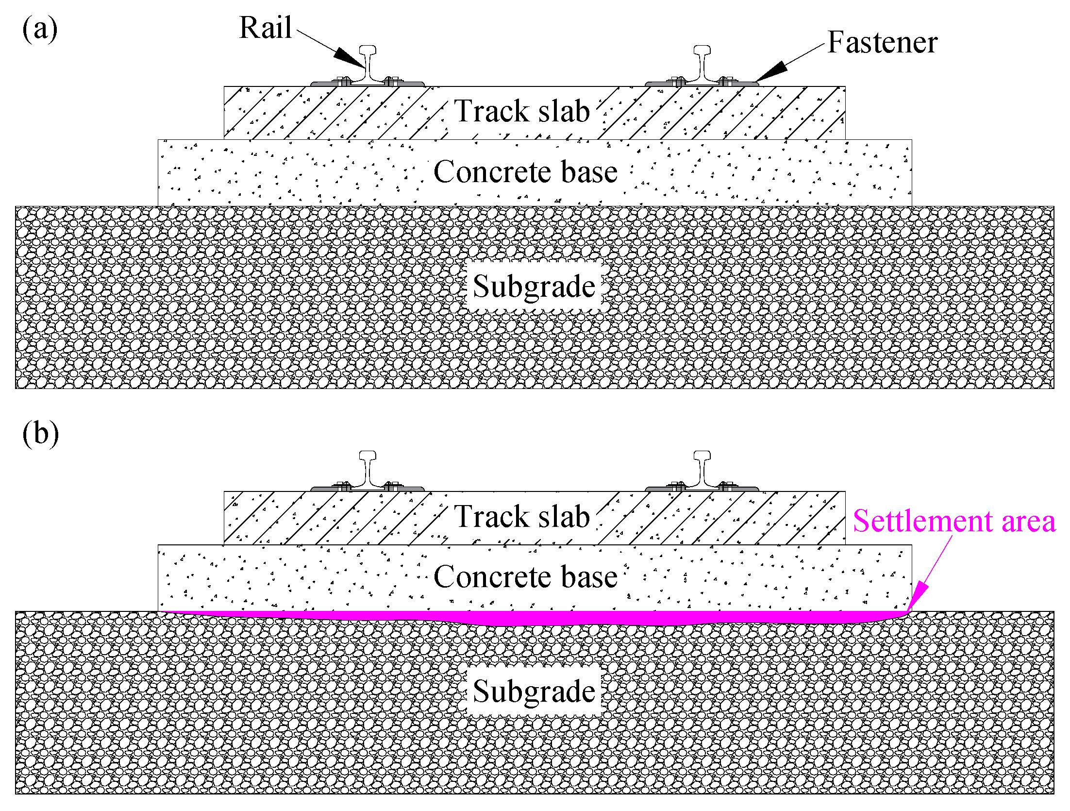
Figure 1. The slab track system; (a) normal state; (b) settlement.
Polymers 16 00404 g001
Figure 2. Lifting the slab track by using lifting jacks; (a) illustration of the method, (b) placing the lifting jack (Weituo-Jingkou Railway), and (c) grouting into the bottom of the concrete base (Weituo-Jingkou Railway).
Polymers 16 00404 g002
Figure 3. Lifting the slab track by grouting foam polyurethane; (a) illustration of the method, (b) injecting polyurethane, and (c) leveling monitoring of the rail surface.
Polymers 16 00404 g003
Figure 4. Expansion force testing of foamed polyurethane; (a) preparation of foamed polyurethane, (b) testing equipment (mm), and (c) a physical picture.
Polymers 16 00404 g004
Figure 5. Expansion performances of the polyurethane; (a) expansion pressure–time history, (b) Min-Max normalization, and (c) relationship between the expansion pressure amplitudes and the density of the polyurethane.
Polymers 16 00404 g005aPolymers 16 00404 g005b
Figure 6. Model of the slab track; (a) top view of the layout of the displacement sensors and grouting holes, (b) I-I section, and (c) II-II section (unit: mm).
Polymers 16 00404 g006
Figure 7. Model construction: (a) subgrade bed and the reinforcement cage in E area, (b) paving and vibrating of concrete, (c) curing by being covered with PE film, and (d) drilling the hole.
Polymers 16 00404 g007
Figure 8. Grouting foamed polyurethane; (a) grouting equipment, and (b) grouting.
Polymers 16 00404 g008
Figure 9. Time history curve of lifting displacement; (a) different testing positions, and (b) lifting mechanism.
Polymers 16 00404 g009
Figure 10. Diffusion radius: (a) 1.50 kg, (b) 2.25 kg, (c) 3.00 kg, and (d) 3.75 kg (unit: m).
Polymers 16 00404 g010
Figure 11. Time history curve of the mean lifting displacement ( L ¯ T).
Polymers 16 00404 g011
Figure 12. Parameters analyses; (a) Lf, (b) t0, (c) μ2, and (d) t2.
Polymers 16 00404 g012
Figure 13. Lifting mechanism analyses; (a) analyses of parameter tg, and (b) calculated values and testing values of the lifting displacement.
Polymers 16 00404 g013
Table 1. Physical properties of raw materials.
(a)
Raw MaterialsHydroxyl Value
(mgKOH/g)
FunctionalityViscosity (25 °C)
(mPa·s)
Water Content
(%)
Acid Value
(%)
PAPI-2.6~2.7150~250-≤0.03
MDI 4118P450 ± 204~4.57000 ± 1000≤0.15%-
POP 214019.5~22.527000≤0.05%≤0.10
(b)
Raw MaterialsMelting Point
(°C)
Boiling Point
(°C)
Flash Point (mPa·s)Purity
(%)
TEDA1581745099.5
BDO2022812199
(c)
Raw MaterialsSpecific Weight (25 °C)Surface Tension (25 °C)
(mN/m)
Viscosity (25 °C)
(mPa·s)
Cloud Point
(°C)
Purity
(%)
PMP1.0823.6900~15004599.9
Table 2. Key values of the lifting testing.
No.mt (kg)tg (s)Lf (mm)r (m)t1 (s)t2 (s)
A3.0186.660.501980
B4.5298.400.531895
C6.04110.090.5518117
D7.55312.730.5616133
Table 3. Values of parameters.
NO.Lf (mm)t0 (s)μ2 (s)t2 (s)
TestCALCRETestCALCRETestCALCRETestCALCRE
A6.666.37−4.35%44.436041.9211−5.66%5.55525.5403−0.27%80800.00%
B8.408.551.79%48.808248.7521−0.11%4.69394.71370.42%95961.05%
C10.0910.544.46%51.410353.80094.65%4.17324.20320.72%117115−1.71%
D12.7312.40−2.59%56.254959.13515.12%3.88093.8455−0.91%1331340.75%
Disclaimer/Publisher’s Note: The statements, opinions and data contained in all publications are solely those of the individual author(s) and contributor(s) and not of MDPI and/or the editor(s). MDPI and/or the editor(s) disclaim responsibility for any injury to people or property resulting from any ideas, methods, instructions or products referred to in the content.