Article

Enhancing Amplification in Compliant Mechanisms: Optimization of Plastic Types and Injection Conditions

1
Faculty of Mechanical Engineering, Ho Chi Minh City University of Technology and Education, Ho Chi Minh City 71307, Vietnam
2
Faculty of Mechanical Engineering, Industrial University of Ho Chi Minh City, Nguyen Van Bao Street, Ward 4, Go Vap District, Ho Chi Minh City 70000, Vietnam
*
Author to whom correspondence should be addressed.
Polymers 2024, 16(3), 394; https://doi.org/10.3390/polym16030394
Submission received: 4 November 2023 / Revised: 19 January 2024 / Accepted: 25 January 2024 / Published: 31 January 2024
(This article belongs to the Special Issue Injection Molding of Polymers and Polymer Composites)

Abstract

:
This study surveys the impacts of injection parameters on the deformation rate of the injected flexure hinge made from ABS, PP, and HDPE. The flexure hinges are generated with different filling time, filling pressure, filling speed, packing time, packing pressure, cooling time, and melt temperature. The amplification ratio of the samples between different injection parameters and different plastic types is measured and compared to figure out the optimal one with a high amplification ratio. The results show that the relationship between the input and output data of the ABS, PP, and HDPE flexure hinges at different injection molding parameters is a linear relation. Changing the material or many injection molding parameters of the hinge could lead to a great impact on the hinge’s performance. However, changing each parameter does not lead to a sudden change in the input and output values. Each plastic material has different optimal injection parameters and displacement behaviors. With the ABS flexure hinge, the filling pressure case has the greatest amplification ratio of 8.81, while the filling speed case has the lowest value of 4.81. With the optimal injection parameter and the input value of 105 µm, the ABS flexure hinge could create a maximum average output value of 736.6 µm. With the PP flexure hinge, the melt temperature case achieves the greatest amplification ratio of 6.73, while the filling speed case has the lowest value of 4.1. With the optimal injection parameter and the input value of 128 µm, the PP flexure hinge could create a maximum average output value of 964.8 µm. The average amplification ratio values of all injection molding parameters are 6.85, 5.41, and 4.01, corresponding to ABS, PP, and HDPE flexure hinges. Generally, the ABS flexure hinge has the highest amplification ratios, followed by the PP flexure hinge. The HDPE flexure hinge has the lowest amplification ratios among these plastic types. With the optimal injection parameter and the input value of 218 µm, the HDPE flexure hinge could create a maximum average output value of 699.8 µm. The results provide more insight into plastic flexure hinges and broaden their applications by finding the optimal injection parameters and plastic types.

1. Introduction

Recently, flexure hinges have been intensively investigated for precision actuation due to their complexity and low cost [1,2,3,4]. Flexure hinges work as a displacement amplification mechanism with no friction force and backlash; therefore, they can replace the conventional system such as motors in super precision machines in lithography, space telescopes, microelectromechanical systems, and optical devices [5,6,7,8]. Some metals and alloys are usually stainless steel, titanium-based, copper-based, and aluminum alloys to create a flexure hinge [9,10,11,12]. The metal-based alloy flexure hinges provide good elastic properties and high corrosion resistance. For example, Wei et al. [13] created a SUS 316L stainless steel hinge from 3D printing. The report showed that the porous layer thickness of the hinge is like the average diameter of the powder particle. Coemert et al. [14] generated Ti-6Al-4V flexure hinges via laser cutting. The results indicated that the payload value is proportional to the hinge width but inversely proportional to the length. Interestingly, Roopa et al. [15] studied the impacts of geometry and material on the displacement of stainless steel, beryllium copper, and brass flexure hinges. They pointed out that the deflection values of the flexure hinge are 6.75 µm, 10.89 µm, and 12.10 µm, corresponding to stainless steel, beryllium copper, and brass materials. Schlick et al. [16] reported an aluminum gripper based on a flexure hinge mechanism. The gripper was applied as a micro-assembly station, and the momentum can be limited by controlling the oscillation via the actuator, lowering the gripping jaw speed, and moving coil actuators.
Flexure hinges with compliant mechanisms could have many designs, depending on the purposes, such as displacement amplifiers, smart structures, robotics, and quasi-static mechanisms. Typically, compliant flexure hinges for displacement amplifier applications have many types such as bridge type, Rhombus type, differential amplifier, lever mechanism, five bar structure, and tensural types. Compared to other designs, a bridge-type flexure hinge has the advantages of a simple and symmetrical shape, high load capacity, and high amplification ratio. Generally, flexure hinges are usually created using metals. However, fabricating a flexure hinge from these material types often requires a lot of time and cost because of the complicated structure and the high precision of the hinge. Using alternative materials with better productivity in fabricating flexure hinges is a rigorous demand. For example, Mutlu et al. [17] used TPE to produce a 3D printing flexure hinge and pinpointed that the elliptic and non-symmetric shapes have the best quality. Rosa et al. [18] created a flexure-based nanopositioner using cyclic olefin copolymer (COC) via the mesoscale injection molding process. The travel range of the COC nanopositioner is 15 µm with the highest standard deviation being 52.3 nm. Notably, Sahota et al. [19] simulated a fiber Bragg grating pressure sensor by comparing ABS polymer and stainless steel flexural hinges. The simulation results showed that the sensitivity of the ABS flexural hinge is 16 times higher than that of the stainless steel one. Shen et al. [20] combined bridge type and lever type mechanisms to generate a hybrid one, achieving a high amplification ratio and low overstress. Abedi et al. [21] designed a bridge-type compliant mechanism with an S-shape, achieving an amplification ratio of 4.5–5.5. Shi et al. [22] created a microgripper with two bridge-type parallelogram amplification mechanisms, obtaining a high amplification ratio of 30.3. Chen et al. [23] used a hybrid-compliant mechanism with a bridge-type and a lever-type design to harvest the vibration energy. Wan et al. [24] optimized the design process of the flexure-based bridge-type amplification using a reliability-based design optimization method. This method provided good accuracy compared to the other traditional methods. Overall, plastic flexural hinge investigations are not popular and need more insight.
Injection molding is a popular technique that could produce plastic parts at a mass production level due to its advantages of industrial availability, high accuracy, short time, and affordable cost [25,26,27,28]. Injection molding, therefore, is widely applied in generating household products and industrial parts. Moreover, advanced injection molding techniques such as microinjection molding, gas-assisted molding systems, conformal cooling channels, metal injection molding, foam injection molding, and water-assisted injection molding have received much interest from authors [29,30,31]. Injection molding can be applied with many thermoplastic polymers such as HDPE, LDPE, PP, ABS, and PA [32,33,34,35]. However, the reports about plastic flexure hinges generated using the injection molding process are rarely discussed despite the advantages of this fabrication technique.
This investigation focuses on creating plastic bridge-type mechanism flexure hinges with a leaf hinge from different plastic types including ABS, PP, and HDPE. The injection parameters including filling time, filling pressure, filling speed, packing time, packing pressure, cooling time, and melt temperature are also surveyed to optimize the hinge performance. The amplification ratio of the samples is evaluated and compared across several injection parameters and plastic types to determine the optimal one with a high amplification ratio. The results provide more insight into plastic flexure hinges and broaden their applications by finding the optimal injection parameters and plastic types.

2. Experimental Methods

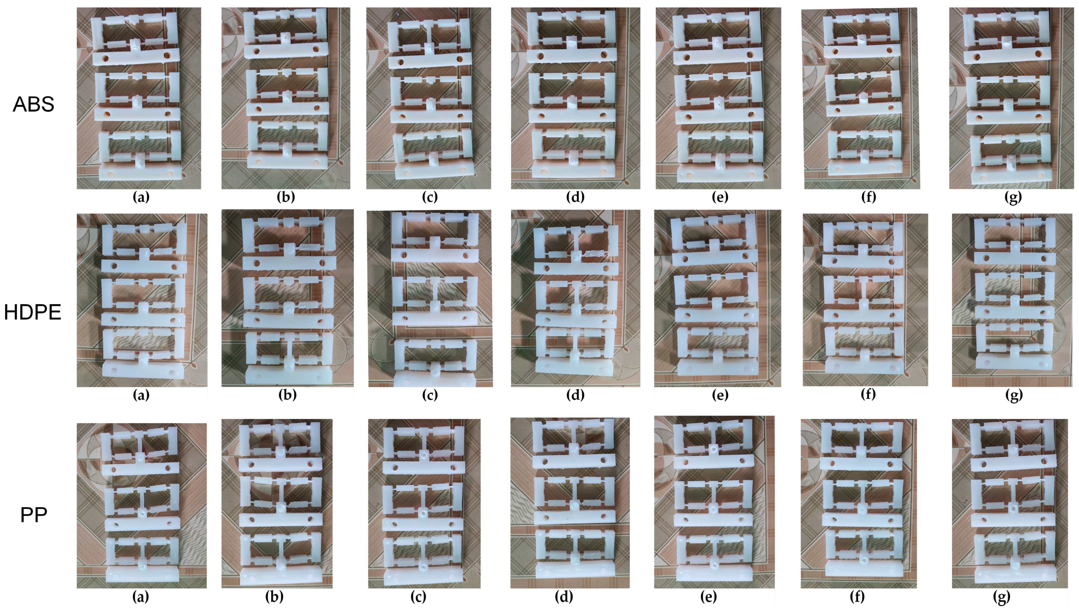
Figure 1 shows the flexure hinge design and the injected hinge. The injection gate dimension is 5 mm in diameter. The compliant mechanism of the flexure hinge with input and output position, the fixture of the hinge, and the measurement device with chronographs for measuring the displacement of the hinge are presented in Figure 2. The measurement procedure consists of three steps. Step 1: Attach the sample to the bracket in the proper position and then attach the chronographs. Step 2: Align the pusher with the measuring model and adjust it. All chronographs had to be reset to zero. Step 3: Turn the pusher handle, then watch the chronographs and record the results. For each sample number, the study injected three plastic hinges for an individual measurement. The average number of three samples is calculated and presented in this report. The standard deviation varies by around 1–7%. Figure 3 presents the flexure hinge at different plastics and injection conditions. Besides holding time and holding pressure, the study also applied packing time and packing pressure. They are the extra steps of the injection molding cycle in which pressure is applied to the polymer melt to compress the polymer and drive additional material into the mold. This compensates for shrinkage as the polymer cools from the melt temperature to the room temperature. The gate is closed during the packing operation to prevent material from entering the mold. Moreover, the molding part weight is about 12–13.7 g, which is suitable for the holding and cooling time.
After the setup of the experiment machines, the plastics are dried at 85 °C for 12 h to remove the humidity. Then, they are injected into the mold using an injection molding. Finally, the injection flexure hinge is tested using a fixture and measurement device. This machine has a screw diameter of 36 mm, an injection capacity of 157 g, a screw speed of 122 mm/s, a 3 mm nozzle with a temperature limit switch control, and a clamping force of 1200 kN. Injection molding parameters depend on the geometric features of the moldings (especially thickness), the flow path of the polymer melt, the number of injection points, the type of polymeric material, the injection machine, etc. During the initial step, which is the experimental setup, this study tried many injection parameters for different plastic types to ensure that the samples were successfully injected. Firstly, this study attempted with relatively low parameters, in which the samples were partially injected. An attempt to inject the molded part was made by gradually increasing the values of the parameters. After that, the injection parameters are gradually adjusted to improve the injection quality. Finally, after having enough information, the injection parameters are set up as shown in Table 1 and Table 2. The injection machine in this report is MA 1200III (Haitian, China). The weights of the moldings are 12 g, 12.7 g, and 13.7 g, corresponding to the PP, HDPE, and ABS hinges.
The injection rate of the screw is 154 cm3/s. The filling speed is presented based on the number “154 cm3/s”. The percentage presents the ratio between the selected filling speed and the number “154 cm3/s”. Regarding the mold temperature, this study does not apply a mold temperature assistance system. Therefore, the mold temperature could be 30 °C. These hinges are injected with different injection molding parameters and different plastics. Table 1 shows the injection mold parameters of the ABS hinge, while Table 2 illustrates the injection molding parameters of the PP and HDPE hinges. The filling time is set at 1.5–2.8 s because the study did not apply the maximum filling pressure and filling speed of the injection molding machine MA 1200III. Therefore, it requires more time to fill the mold cavity than the maximum condition. The injection pressure is quite low; however, it is enough to fill the mold cavity with a suitable filling time (1.5–2.8 s). Because the study did not use the injection molding machine MA 1200III’s maximum filling pressure and filling speed, the filling speed is set from 50% to 70%. As a result, a higher filling speed is required to fill the mold cavity than under the maximum condition. The study applied only 75–83% of this number, and according to the moderate pressure and volume of the runner system, the filling time must be greater than 2.0 s to ensure a good filling stage. Moreover, the subsequent packing stages (or holding stages) will ensure the product is filled with melt during the cooling phase, as shown in Table 1.
ABS 750 SW polymer is supplied by Kumho Petrochemical, Seoul, Republic of Korea. PP polymer named Advanced-PP 1100 N is manufactured by Advanced Petrochemical Company, Al Jubail, Saudi Arabia. HDPE polymer HTA 108 is manufactured by Exxon Mobile Petroleum and Chemical Company, Riyadh, Saudi Arabia. The Young’s modulus of ABS, PP, and HDPE are 3110 MPa, 1550 MPa, and 1300 MPa, respectively.

3. Results and Discussion

3.1. ABS Flexure Hinge

In this section, the effects of injection parameters on the displacement of the ABS flexure hinge are examined. Firstly, the impacts of the filling stage, including filling time, filling pressure, and filling speed, are surveyed.
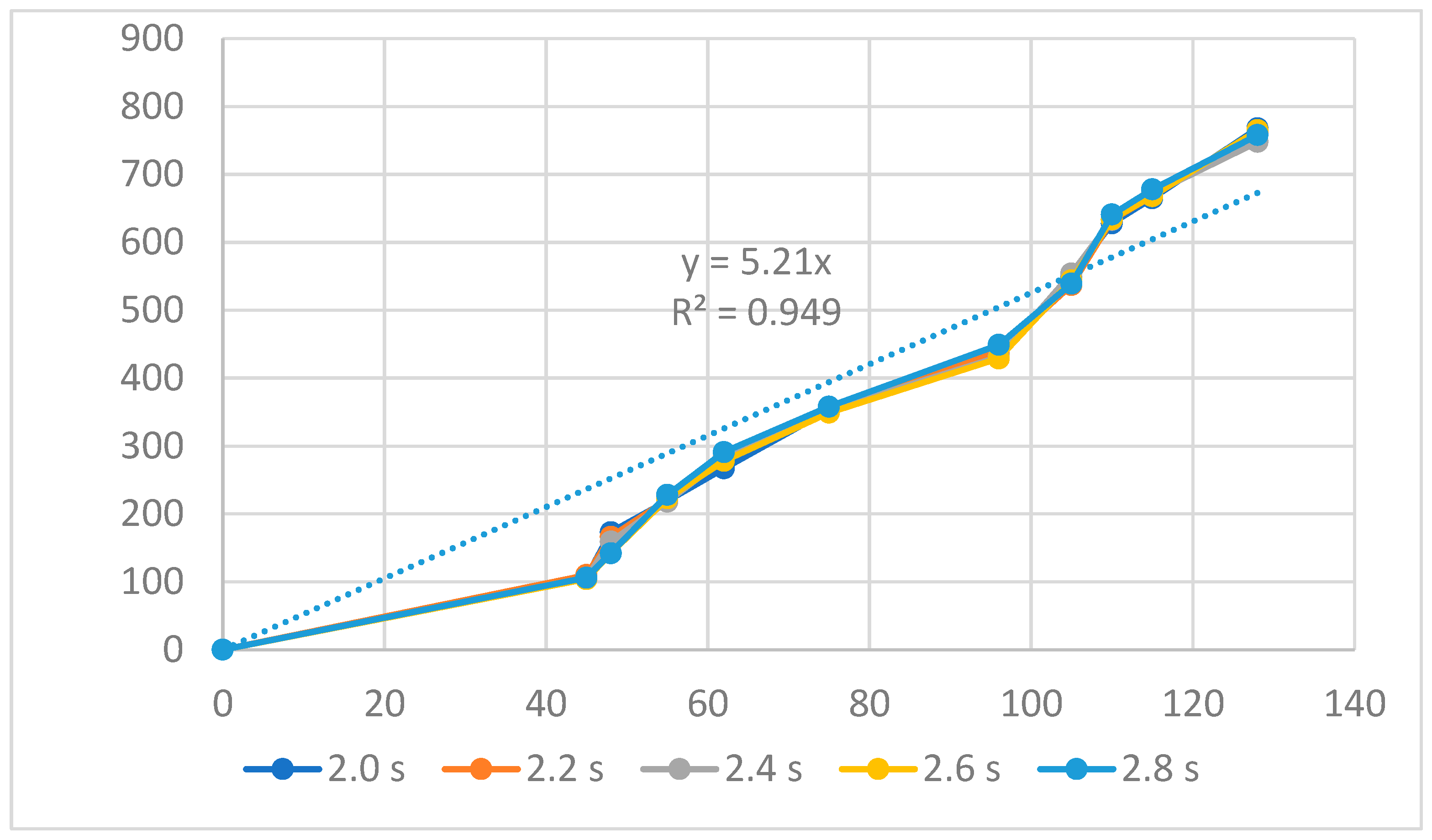
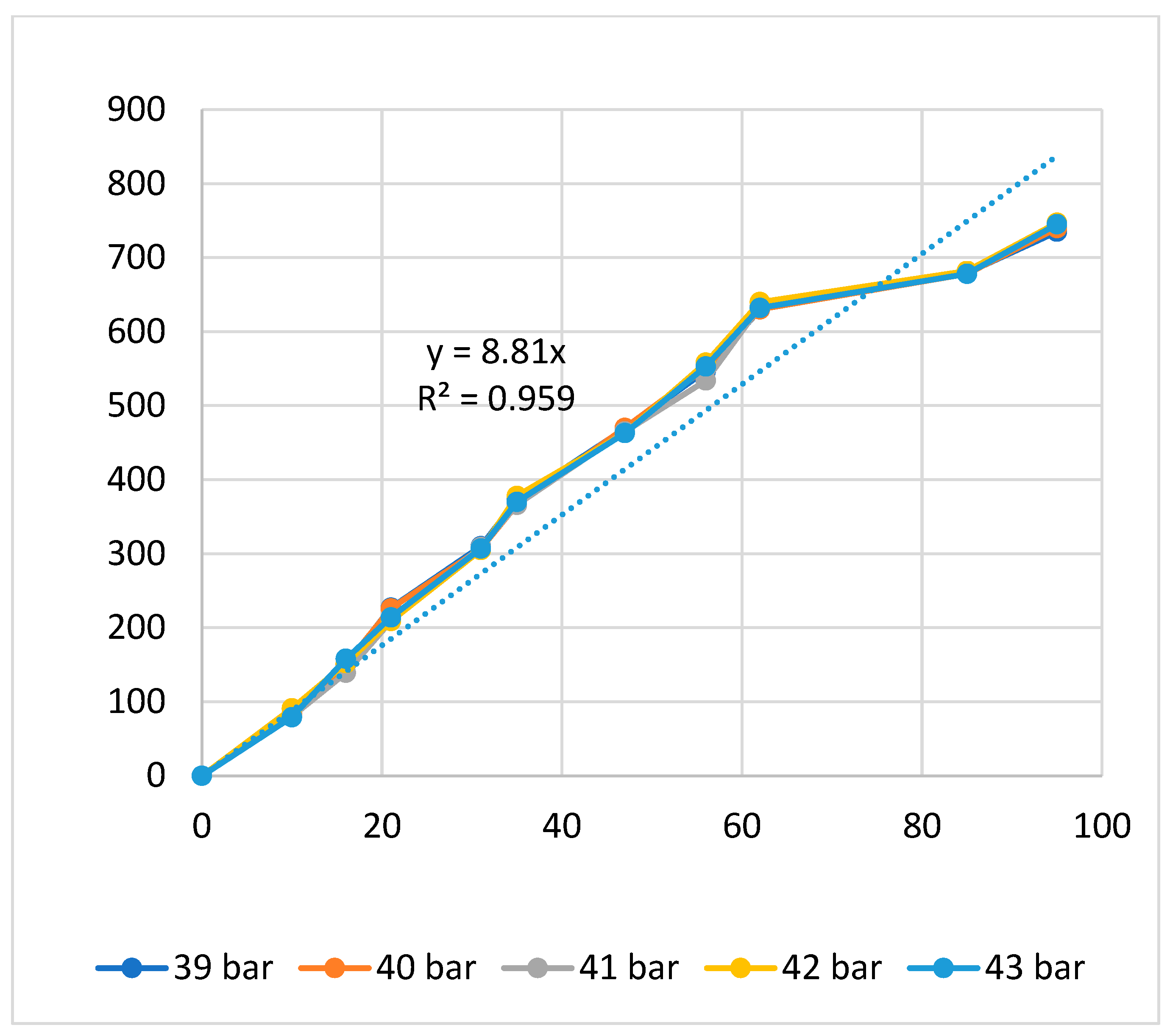
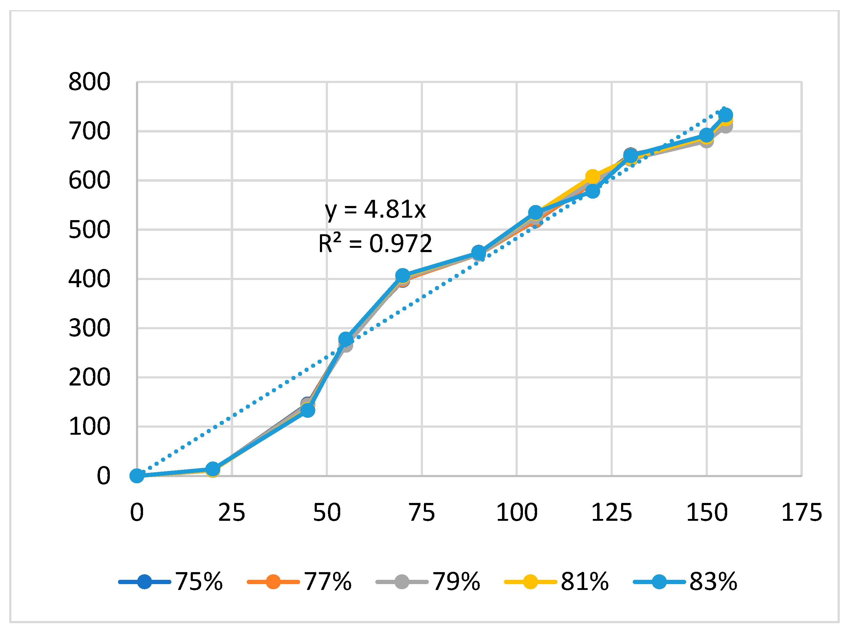
Figure 4, Figure 5 and Figure 6 present the displacement diagrams of the ABS flexure hinge at different filling times, filling pressures, and filling speeds. In the filling time case, with the maximum input value of 128 µm, the average output value is 760.4 µm, indicating the magnification effect of the hinge, as shown in Figure 4. Generally, changing the filling time, filling pressure, and filling speed does not strongly affect the displacement rate of the ABS flexure hinge due to the similar values of the curves at different filling times and filling pressures. In addition, improving the input value mostly leads to a linear increase in the output value. The regression equations between the average values of the input and the output displacements are
y1 = 5.21x1,
y2 = 8.81x2,
y3 = 4.81x3,
where y1, y2, and y3 are the output data and x1, x2, and x3 are the input data of the ABS flexure hinge at different filling times, filling pressures, and filling speeds.
The trendline diagrams are set as a linear relationship y = a.x + b, where “b” is zero because the intercept of the trendline is set at zero. Therefore, there is only the “a” regression coefficient in the equation y = a.x. Moreover, the R-squared value of these trendlines is very high, which is higher than 0.9, indicating that the equation has a good prediction value.
This equation indicates a linear relationship between the input and the output data, as mentioned above. The amplification ratio of the filling time case is 5.21, the filling pressure case is 8.81, and the filling speed is 4.81. These values mean that the filling pressure cases have the highest amplification ratio, indicating the strong effect of the filling pressure on the amplification ratio. On the contrary, the filling speed has the lowest amplification ratio, meaning a weaker effect rate than the filling pressure and the filling time.
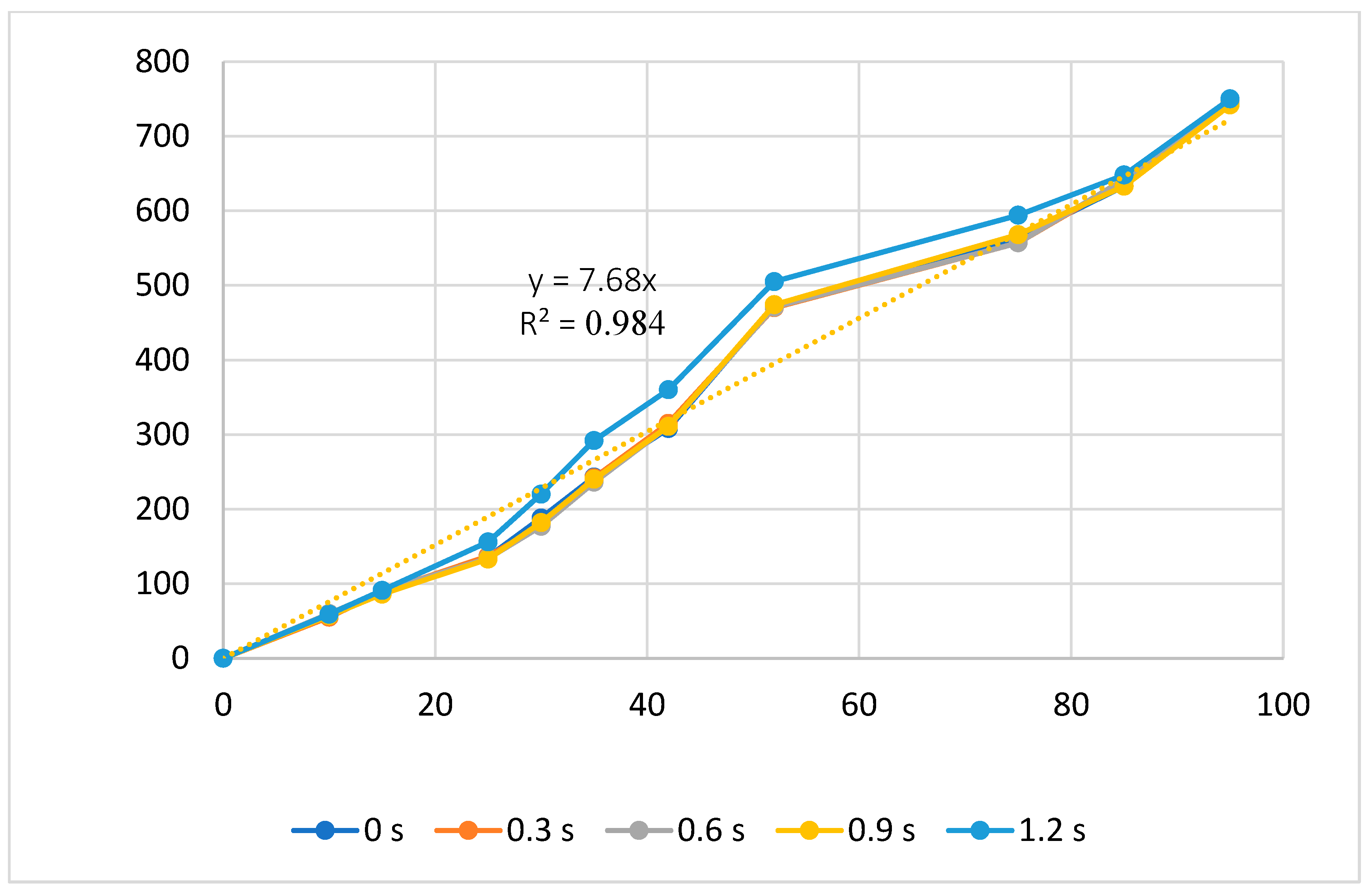
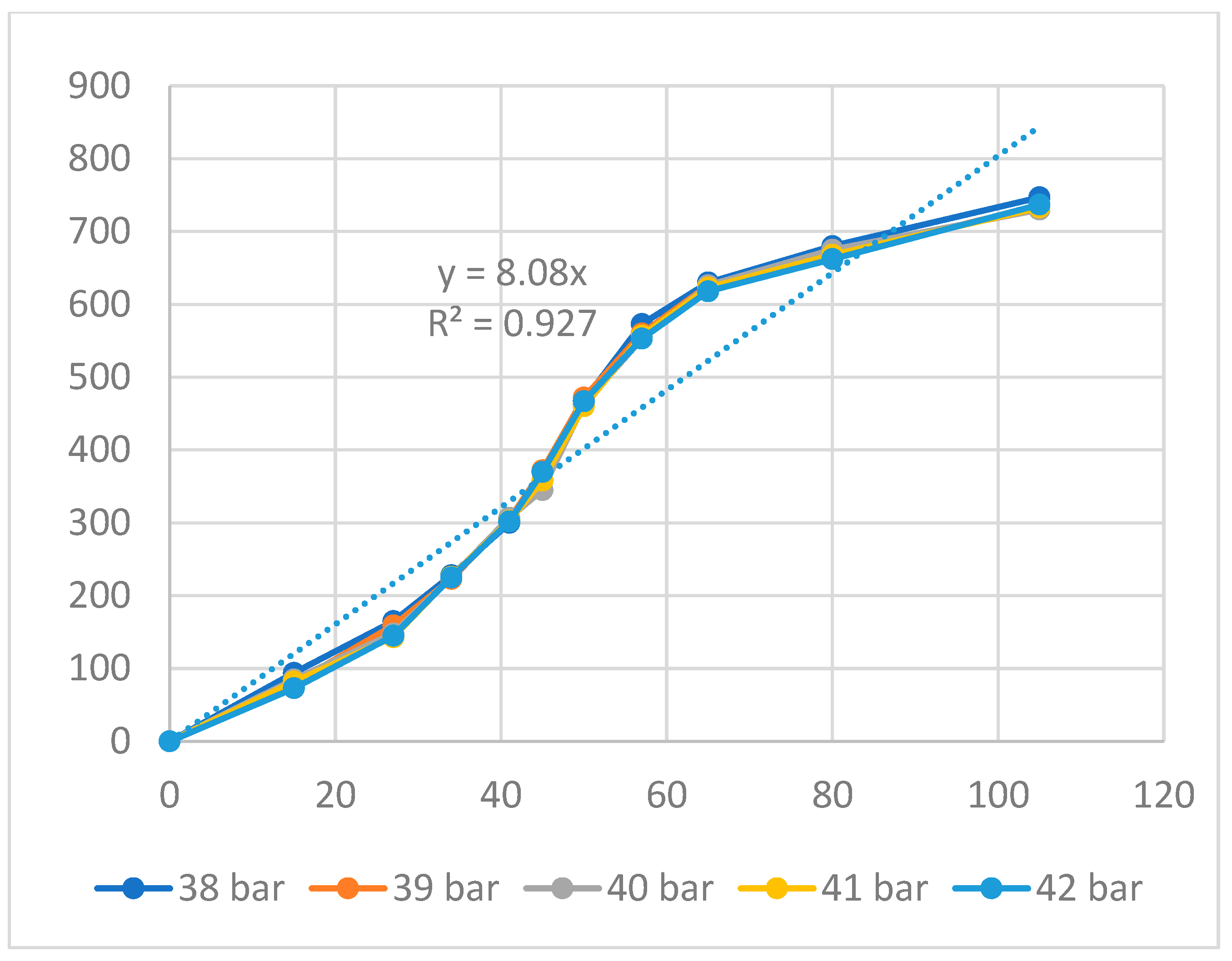
Figure 7 and Figure 8 present the displacement of the ABS flexure hinge at different packing times and packing pressures. Consistent with the filling stage results, the similar values at different packing times and packing pressures reveal that altering these values does not cause much change in the displacement rate. Moreover, the regression equations between the average values of the input and the output displacements are
y4 = 7.68x4,
y5 = 8.08x5,
where y4 and y5 are the output data and x4 and x5 are the input data of the ABS flexure hinge at different packing times and packing pressures.
These data have a linear relationship, which is similar to the filling stage. The amplification ratio values for the packing time and packing pressure cases are 7.68 and 8.08, respectively. These ratios are comparable, unlike the filling stage, where the filling pressure has a larger amplification ratio than the filling time.
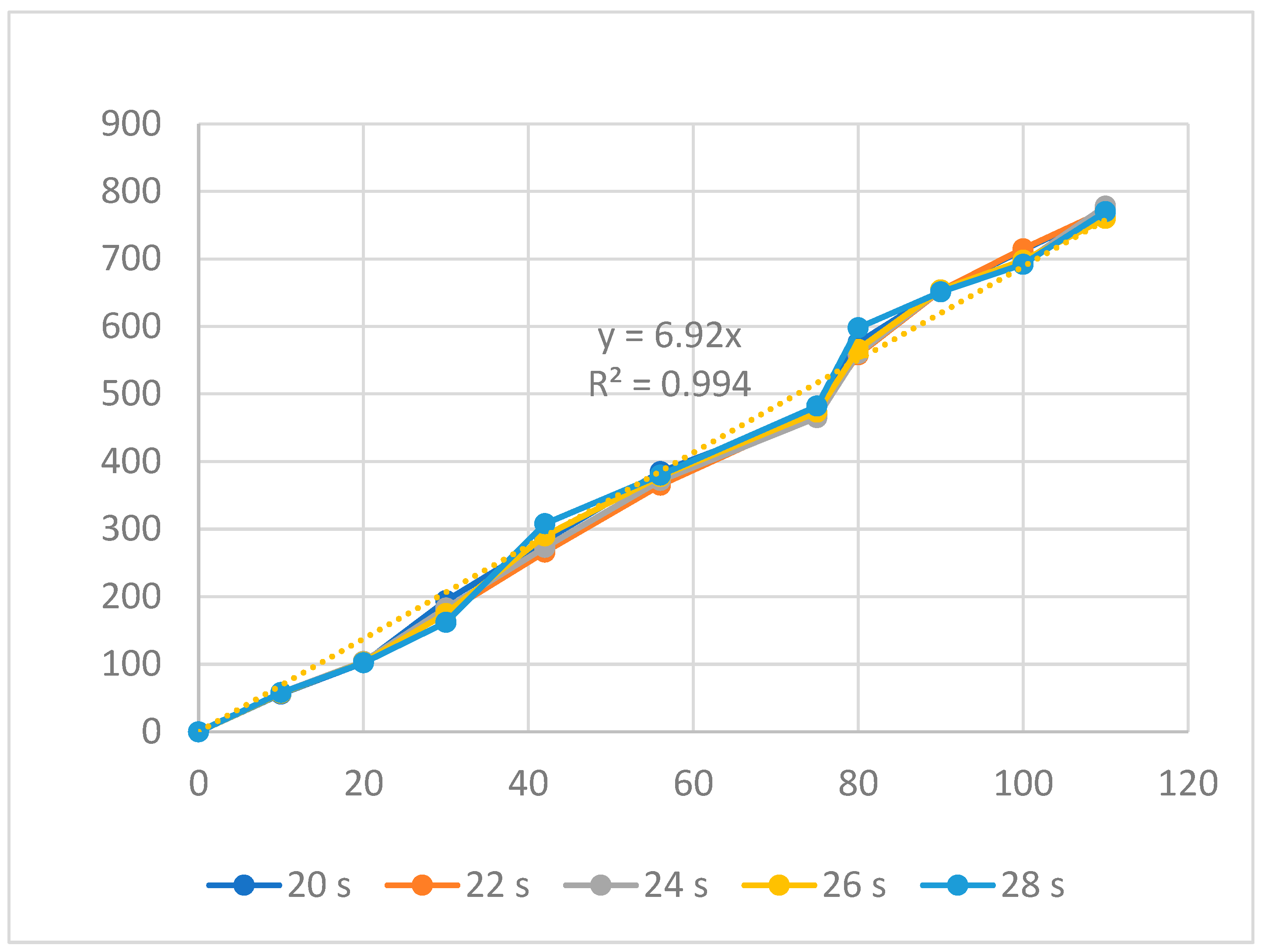
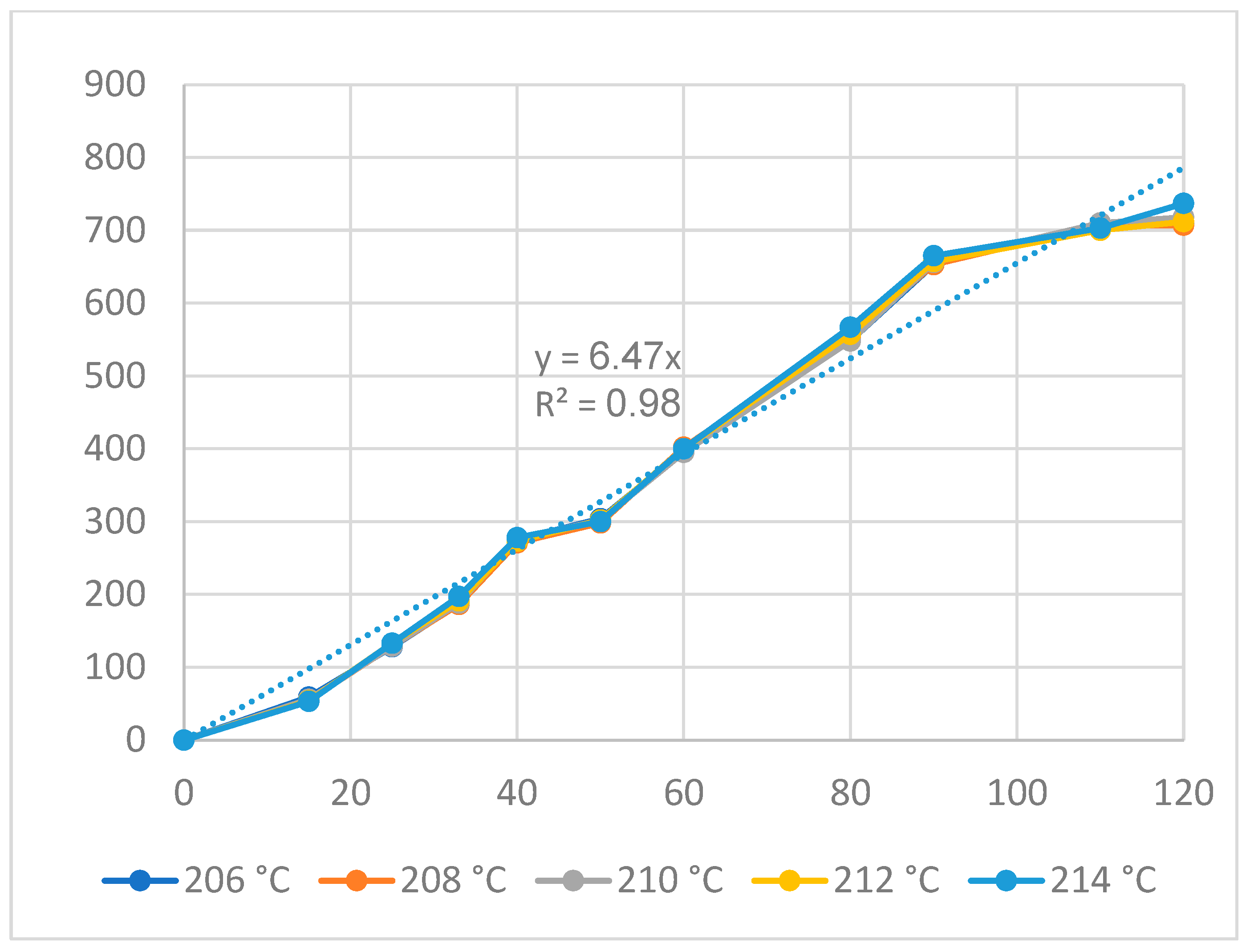
Figure 9 and Figure 10 display the displacement of the ABS flexure hinge at different cooling times and melt temperatures. The curve diagrams for different parameters in every figure are almost equivalent, demonstrating that changing the cooling time and melt temperature has little effect on the displacement rate. Furthermore, the regression equations between the average values of the input and output displacements are as follows:
y6 = 6.92x6,
y7 = 6.47x7,
where y6 and y7 are the output data and x6 and x7 are the input data of the ABS flexure hinge at different cooling times and melt temperatures.
The linear relationship between the input and output data is revealed by Equations (6) and (7), which are similar to the filling and packing stages. The amplification ratio values for the cooling time and melt temperature cases are 6.92 and 6.47, respectively. The results reveal that the cooling time case has a higher amplification ratio, resulting in a higher effect rate.
Overall, the relationship between the input and output data of the ABS flexure hinges at different injection molding parameters is linear. The amplification ratio values for filling time, filling pressure, filling speed, packing time, packing pressure, cooling time, and melt temperature are 5.21, 8.81, 4.81, 7.68, 8.08, 6.92, and 6.47. The amplification ratio of filling pressure is the highest, while that of filling speed is the lowest. The range of the filling pressure examined is 39–43 bar. In this range, the amplification ratio is highest due to the good quality of the sample following the parameters of filling time 2.4 s, filling pressure 39–43 bar, packing time 0.6 s, packing pressure 40 bar, cooling time 24 s, melt temperature 210 °C, and filling speed 79%, while the filling speed range is 75–83%. In this range, the amplification ratio is lowest due to the lower quality of the sample following the parameters of filling time 2.4 s, filling pressure 41 bar, packing time 0.6 s, packing pressure 40 bar, cooling time 24 s, melt temperature 210 °C, and filling speed 75–83%.
Interestingly, the packing stage also shows high amplification ratio values of 7.68 and 8.08, pinpointing the important role of this stage in optimizing the ABS flexure hinge. Most importantly, the results reveal that the curve diagrams of each figure are mostly similar because changing each parameter does not lead to a sudden change in the input and output value. In general, the injection parameters strongly impact the amplification ratio of the ABS hinge. In other words, changing a set of injection parameters could lead to a greater impact on the hinge’s performance. The amplification ratio could range from 4.81 to 8.81, which is a relatively large deviation. The reason for this phenomenon is the sensitivity of the ABS flexure hinge performance when changing the injection parameters. The plastic injection hinge design with thin hinge corners especially requires suitable injection parameters to successfully fill the mold cavity because the plastic melt flow is hindered in these thin areas. The presented injection parameters are ideal for forming the ABS flexure hinge.
Overall, the amplification ratio of the ABS flexure hinge varies in the range of 4.81–8.81. In Kim et al.’s report [37], a similar aluminum alloy flexure hinge has an amplification of 5–25. The amplification ratio of the ABS hinge is lower than that of the aluminum alloy one. The reason is the higher strength and stiffness of the aluminum alloys compared to the ABS plastic.

3.2. PP Flexure Hinge

This section examines the influences of injection parameters on the displacement of the PP flexure hinge. In the previous section, the results reveal that the curve diagrams of each figure are mostly similar because changing each parameter does not lead to a sudden change in the input and output value. Furthermore, linear relationships are popular in all cases of the ABS flexure hinge. As a result, this section concentrates on the average value of each parameter. First, the impact of the filling stage is addressed, which includes filling time, filling pressure, and filling speed.
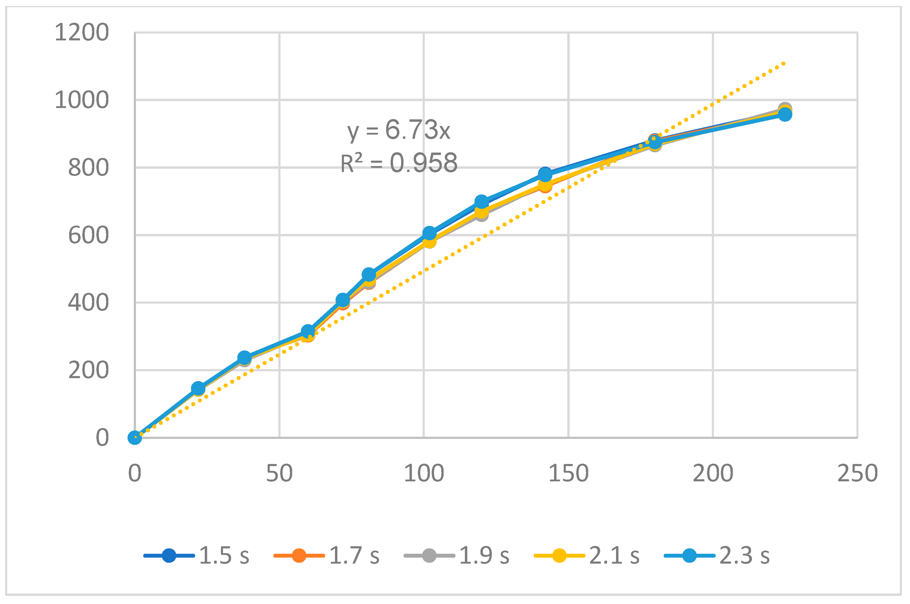
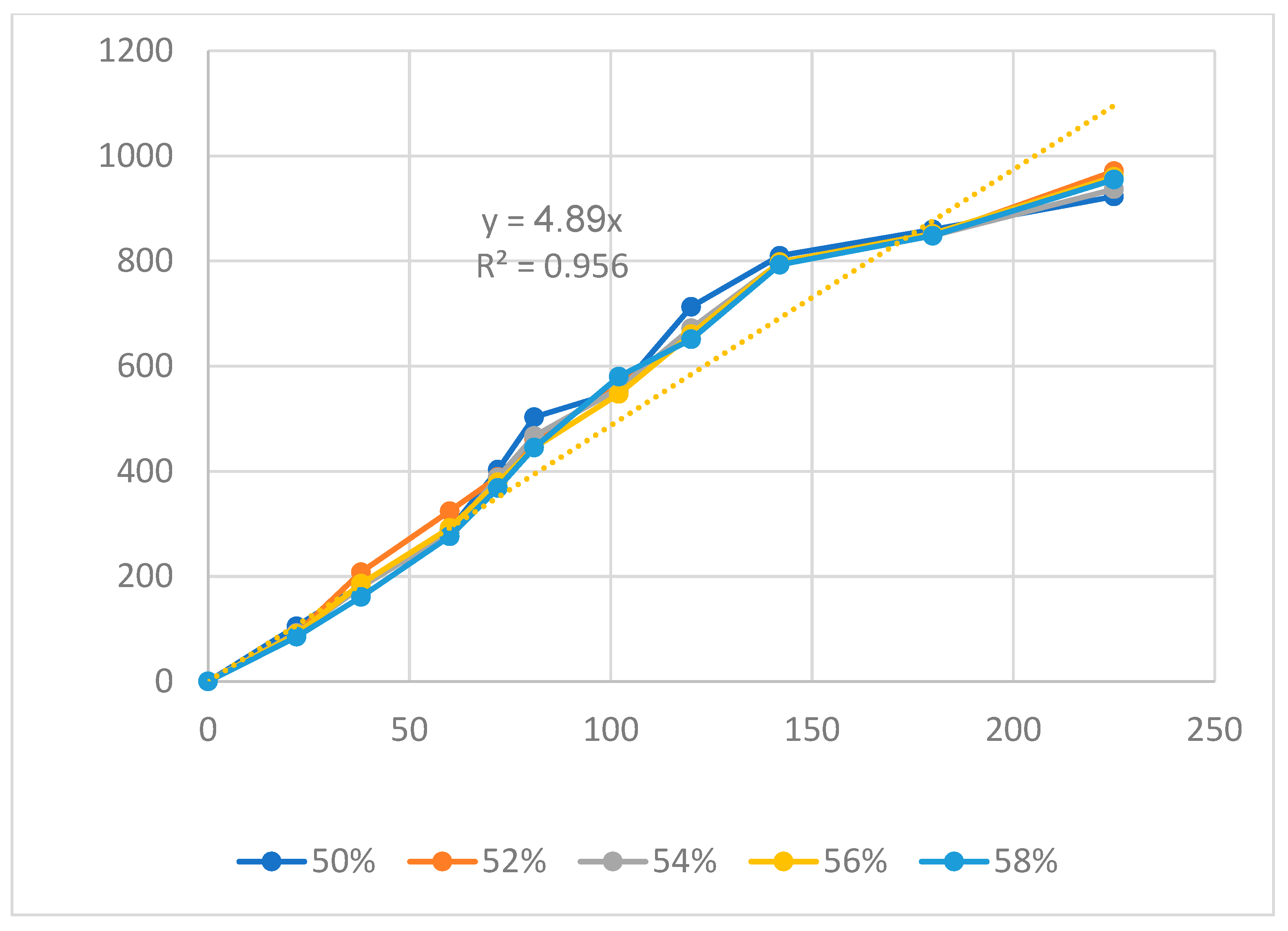
Figure 11, Figure 12 and Figure 13 display the displacement diagrams of the PP flexure hinge at different filling times, filling pressures, and filling speeds. Following calculations, the regression equations demonstrating the linear relationship between the average values of the input and output displacements are
y8 = 6.73x8,
y9 = 4.58x9,
y10 = 4.89x10,
where y8, y9, and y10 are the output data and x8, x9, and x10 are the input data of the PP flexure hinge at different filling times, filling pressures, and filling speeds.
The amplification ratio of the filling time case is 6.73, the filling pressure case is 4.58, and the filling speed case is 4.89. Different from the ABS flexure hinge, in which the filling pressure has the highest amplification ratio, the filling time case achieves the highest amplification ratio of 6.83. On the other hand, the filling pressure case has the lowest amplification ratio of 4.58. Compared to the steel alloy flexure hinge with an amplification ratio of 16.2 in Na et al.’s report [38], the PP flexure hinge has a lower value. The reason is that steel alloy has a much higher elastic modulus and strength than PP plastic.
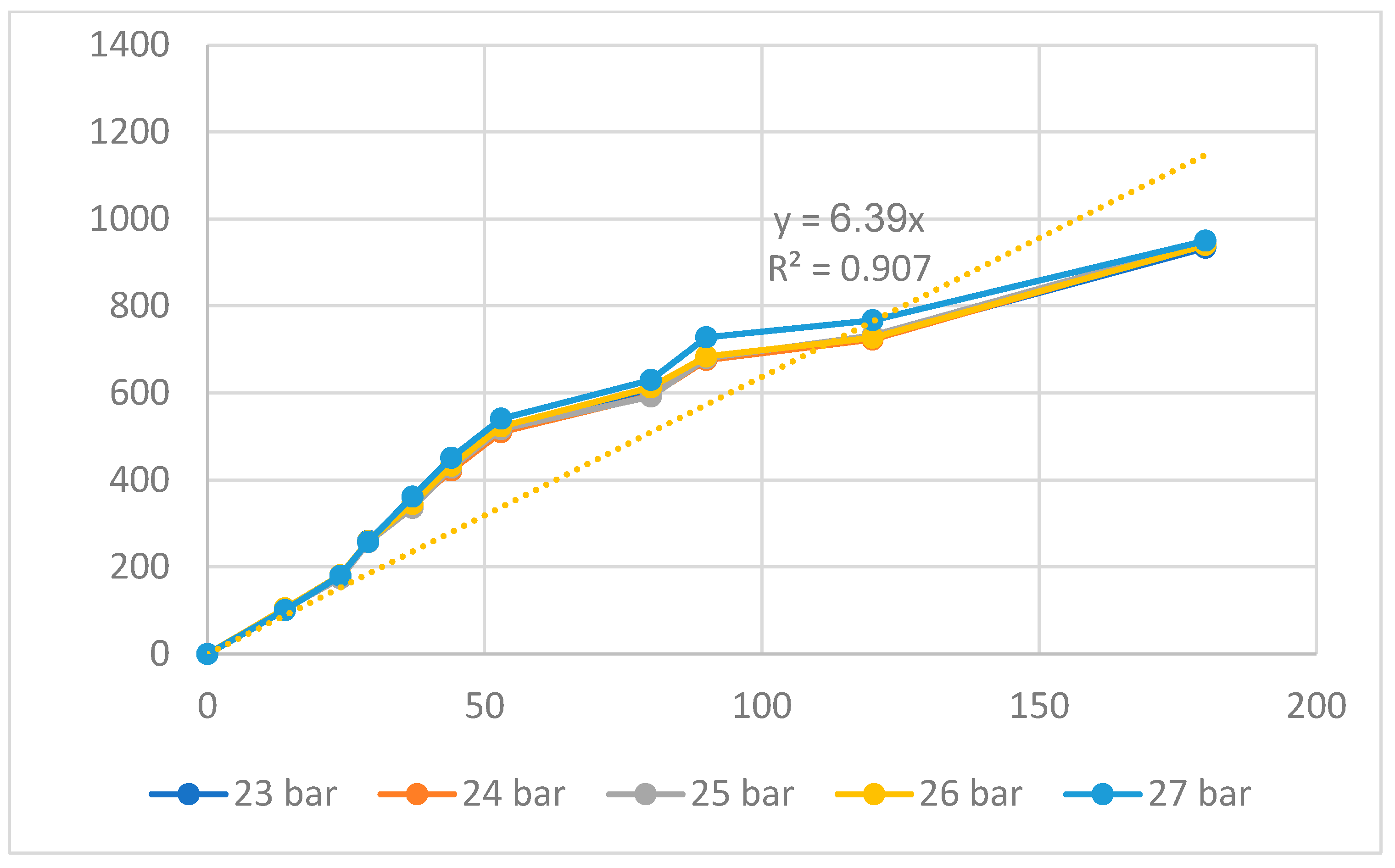
Figure 14 and Figure 15 show the displacement of the PP flexure hinge at different packing times and packing pressures. The regression equations between the average values of the input and the output displacements of the PP flexure hinge are
y11 = 5.08x11,
y12 = 6.39x12,
where y11 and y12 are the output data and x11 and x12 are the input data of the PP flexure hinge at different packing times and packing pressures.
The correlations between these factors are linear. The amplification ratio values for the packing time and packing pressure situations are 5.08 and 6.39, respectively. Because of the lower elastic modulus and tensile strength, these ratios are significantly lower than those of the ABS flexure hinge, which are 7.68 and 8.08.
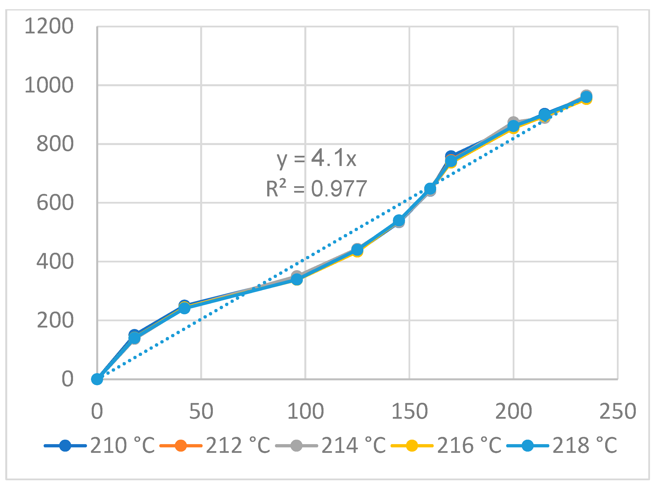
Figure 16 and Figure 17 display the displacement of the PP flexure hinge at different cooling times and melt temperatures. The curve diagrams of the various parameters in each figure are most comparable, demonstrating that changing the cooling time and melt temperature has little effect on the displacement rate. Furthermore, the regression equations between the average values of the input and output displacements are as follows:
y13 = 6.13x13,
y14 = 4.1x14,
where y13 and y14 are the output data and x13 and x14 are the input data of the PP flexure hinge at different cooling times and melt temperatures.
The amplification ratio values for the cooling time and melt temperature cases are 6.13 and 4.1, respectively. The PP flexure hinge has lower amplification ratios than the ABS flexure hinge, which has values of 6.92 and 6.47 due to its lower elastic modulus and tensile strength.
Overall, the amplification ratio values are 6.73, 4.58, 4.89, 5.08, 6.39, 6.13, and 4.1, corresponding to the filling time, filling pressure, filling speed, packing time, packing pressure, cooling time, and melt temperature. The filling time achieves the greatest amplification ratio, while the melt temperature has the lowest one. Notably, these values are mainly lower than the ABS flexure hinge because of the weaker strength. The amplification ratio of the ABS flexure hinge could range from 4.81 to 8.81, while the amplification ratio of the PP flexure hinge could range from 4.1 to 6.73. The suitable amplification ratio could be achieved using two methods: changing the plastic-type or changing the injection parameters. In the next section, the displacement of the HDPE flexure hinge is investigated and then compared to the PP and ABS flexure hinge. Furthermore, the PP flexure hinge’s linear relationship between input and output data is similar to the ABS one.
In general, the amplification ratio of the PP flexure hinge varies in the range of 4.1–6.73. Compared to the amplification ratio of the ABS hinge, the amplification ratio of the PP flexure hinge is slightly lower. Moreover, compared to the Na et al. [38] report, the similar steel flexure hinge has an amplification of 16.2. The amplification ratio of the ABS hinge is lower due to the lower strength and stiffness of the PP plastic compared to the steel material.

3.3. HDPE Flexure Hinge and Comparison

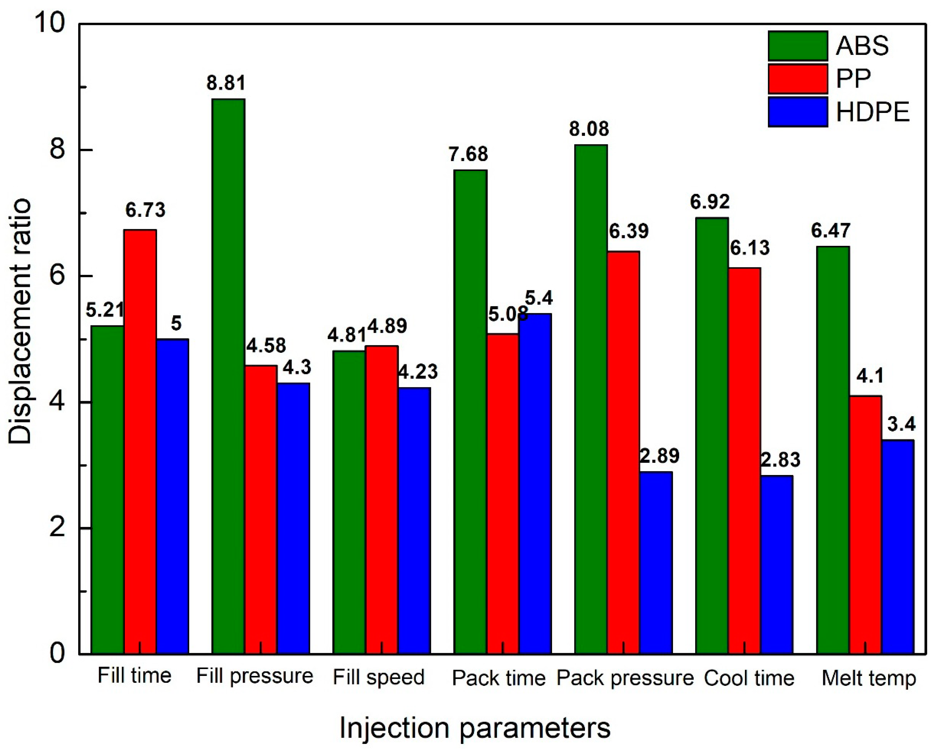
In this section, displacements of the HDPE flexure hinge are surveyed. After that, these data are compared with the previous results of the ABS and PP flexure hinges. The input and output equations at the different filling times, filling pressures, filling speeds, packing times, packing pressures, cooling times, and melt temperatures are presented in Table 3. Figure 18 shows a more visual representation of these results.
Figure 18 shows the comparison of the amplification ratio among ABS, PP, and HDPE flexure hinges. The average amplification ratio values of all injection molding parameters are 6.85, 5.41, and 4.01, corresponding to ABS, PP, and HDPE flexure hinges. Generally, the ABS flexure hinge has the highest amplification ratios, followed by the PP flexure hinge. HDPE flexure hinge has the lowest amplification ratios among these plastic types. The reason is this order’s gradual reduction in the tensile strength and elastic modulus [39]. Moreover, the highest amplification ratio is 8.81, gained by the ABS flexure hinge in the packing pressure case. In reverse, the HDPE flexure hinge in the cooling time case has the lowest amplification ratio of 2.83. The mechanical properties strongly affect the performance of the plastic flexure hinge. The flexure hinge shape, in this case, is not suitable for finding Young’s modulus, as it is not a tensile test sample. The shape of the flexure hinge and the process parameters could impact Young’s modulus value via the degree of crystallinity. The Young’s modulus of ABS, PP, and HDPE are 3110 MPa, 1550 Mpa, and 1300 Mpa, respectively. These values are very useful to explain the average amplification ratio values of these plastic hinges. For ABS, PP, and HDPE flexure hinges, the average amplification ratio values of all injection molding parameters are 6.85, 5.41, and 4.01. Therefore, the higher the Young’s modulus value, the higher the amplification ratio value of the plastic hinges.
The optimal function here is the maximum amplification ratio, which is the “a” factor” in the equation y = a.x. This study tries to find the injection parameters that generate the maximum amplification ratio. In addition, the optimal injection parameter for the ABS flexure hinge with the highest amplification ratio is a filling time of 2.4 s, a filling pressure of 39–43 bar, a filling speed of 79%, a packing time of 0.6 s, a packing pressure of 40 bar, a cooling time of 24 s, and a melt temperature of 210 °C. With these optimal injection parameters and the input value of 105 µm, the ABS flexure hinge could create a maximum average output value of 736.6 µm. The optimal injection parameter for the PP flexure hinge is a filling time of 1.5–2.3 s, a filling pressure of 27 bar, a filling speed of 54%, a packing time of 0.6 s, a packing pressure of 25 bar, a cooling time of 24 s, and a melt temperature of 214 °C. With the optimal injection parameter, and the input value of 128 µm, the PP flexure hinge could create a maximum average output value of 964.8 µm. The optimal injection parameter for the HDPE flexure hinge is like the PP hinge, which is a filling time of 1.5–2.3 s, a filling pressure of 27 bar, a filling speed of 54%, a packing time of 0.6 s, a packing pressure of 25 bar, a cooling time of 24 s, and a melt temperature of 214 °C. With the optimal injection parameter, and the input value of 218 µm, the HDPE flexure hinge could create a maximum average output value of 699.8 µm.
Table 4 presents the amplification ratios of different flexure hinge materials. The aluminum alloys and steel alloys could produce a flexure hinge with a greater amplification ratio compared to the ABS, PP, and HDPE flexure hinges [37,38]. However, the amplification ratios of the ABS, PP, and HDPE flexure hinges are compatible with smart memory alloys and titanium alloys [40,41]. Most importantly, the injection plastic hinges may be mass-produced at a low cost and high productivity level. On the other hand, the cost and difficulty of producing the metallic flexure hinges are significantly higher than those of injection plastic ones. Therefore, the injection plastic hinges could facilitate the application of flexural hinges. In the future, we could examine how different hinge forms and corner shapes affect the functionalities of injection flexure plastic hinges. The fatigue strength of the injection plastic hinge could also be investigated.

4. Conclusions

This study investigates the amplification of the injected plastic flexure hinge. The effects of injection plastics and injection parameters on the amplification ratio of the compliant mechanism flexural hinges are surveyed. The flexural hinge is injected with different plastic types: filling time, filling pressure, filling speed, packing time, packing pressure, cooling time, and melt temperature. Some noteworthy remarks that may be noted include the following:
The injection plastic hinges could be produced at the mass production level with high productivity and low cost. The relationship between the input and output data of the ABS, PP, and HDPE flexure hinges at different injection molding parameters is a linear relation. Changing the hinge’s material or numerous injection molding settings could have a significant impact on its performance.
With the ABS flexure hinge, the packing pressure case has the greatest amplification ratio of 8.81, while the filling speed case has the lowest value of 4.81. The optimal injection parameter for an ABS flexure hinge is a filling time of 2.4 s, a filling pressure of 41 bar, a filling speed of 79%, a packing time of 0.6 s, a packing pressure of 38–42 bar, a cooling time of 24 s, and a melt temperature of 210 °C. The ABS flexure hinge could produce a maximum average output value of 736.6 µm with this parameter and an input value of 105 µm.
The filling time case has the highest amplification ratio of 6.73 with the PP flexure hinge, while the melt temperature case has the lowest value of 4.1. The optimal injection parameter for a PP flexure hinge is a filling time of 1.5–2.3 s, a filling pressure of 27 bar, a filling speed of 54%, a packing time of 0.6 s, a packing pressure of 25 bar, a cooling time of 24 s, and a melt temperature of 214 °C. With this parameter, and the input value of 128 µm, the PP flexure hinge could create a maximum average output value of 964.8 µm.
With the HDPE flexure hinge, the packing time case achieves the greatest amplification ratio of 5.4, while the cooling case has the lowest value of 2.83. The optimal injection parameter for the HDPE flexure hinge is like the PP hinge, which is a filling time of 1.5–2.3 s, a filling pressure of 27 bar, a filling speed of 54%, a packing time of 0.6 s, a packing pressure of 25 bar, a cooling time of 24 s, and a melt temperature of 214 °C. The largest average output value that the HDPE flexure hinge could produce with the ideal injection parameter and an input value of 218 µm is 699.8 µm.
For the ABS, PP, and HDPE flexure hinges, the amplification ratio values of all injection molding parameters are 4.81–8.81, 4.1–6.73, and 2.83–5.4. In general, the ABS flexure hinge could be superior to the PP flexure hinge in terms of amplification ratios. The lowest amplification ratio among these plastic kinds is found in HDPE flexure hinges. The results provide more insight into plastic flexure hinges and broaden their applications by finding the optimal injection parameters and plastic types. In the future, we could analyze the effects of corner shapes and try other hinge shapes on the performance of the flexure plastic hinges.

Author Contributions

P.S.M. and V.-T.N.: conceptualization, funding acquisition; V.-T.N., V.Q.H. and H.N.L.D.: writing—original draft, investigation; T.M.T.U., P.S.M. and V.-T.N.: analyzing, visualization, project administration; V.T.T.N., P.S.M., H.N.L.D. and V.-T.N.: writing—review and editing. All authors have read and agreed to the published version of the manuscript.

Funding

This research was funded by HCMC University of Technology and Education.

Institutional Review Board Statement

Not applicable.

Informed Consent Statement

Not applicable.

Data Availability Statement

The data used to support the findings of this study are available from the corresponding author upon request.

Acknowledgments

The authors acknowledge the support of HCMC University of Technology and Education.

Conflicts of Interest

The authors declare no conflicts of interest.

References

  1. Tian, Y.; Zhang, D.; Shirinzadeh, B. Dynamic modelling of a flexure-based mechanism for ultra-precision grinding operation. Precis. Eng. 2011, 35, 554–565. [Google Scholar] [CrossRef]
  2. Gao, X.; Yang, J.; Wu, J.; Xin, X.; Li, Z.; Yuan, X.; Shen, X.; Dong, S. Piezoelectric actuators and motors: Materials, designs, and applications. Adv. Mater. Technol. 2020, 5, 1900716. [Google Scholar] [CrossRef]
  3. Chen, F.; Zhang, Q.; Gao, Y.; Dong, W. A review on the flexure-based displacement amplification mechanisms. IEEE Access 2020, 8, 205919–205937. [Google Scholar] [CrossRef]
  4. Mutlu, R.; Tawk, C.; Alici, G.; Sariyildiz, E. A 3D printed monolithic soft gripper with adjustable stiffness. In Proceedings of the IECON 2017-43rd Annual Conference of the IEEE Industrial Electronics Society, Beijing, China, 29 October–1 November 2017; pp. 6235–6240. [Google Scholar]
  5. Judy, J.W. Microelectromechanical systems (MEMS): Fabrication, design and applications. Smart Mater. Struct. 2001, 10, 1115. [Google Scholar] [CrossRef]
  6. Shaar, N.S.; Barbastathis, G.; Livermore, C. Integrated folding, alignment, and latching for reconfigurable origami microelectromechanical systems. J. Microelectromech. Syst. 2014, 24, 1043–1051. [Google Scholar] [CrossRef]
  7. Bagolini, A.; Ronchin, S.; Bellutti, P.; Chistè, M.; Verotti, M.; Belfiore, N.P. Fabrication of novel MEMS microgrippers by deep reactive ion etching with metal hard mask. J. Microelectromech. Syst. 2017, 26, 926–934. [Google Scholar] [CrossRef]
  8. Solgaard, O.; Godil, A.A.; Howe, R.T.; Lee, L.P.; Peter, Y.A.; Zappe, H. Optical MEMS: From micromirrors to complex systems. J. Microelectromech. Syst. 2014, 23, 517–538. [Google Scholar] [CrossRef]
  9. Noveanu, S.; Lates, D.; Fusaru, L.; Rusu, C. A new compliant microgripper and study for flexure hinges shapes. Procedia Manuf. 2020, 46, 517–524. [Google Scholar] [CrossRef]
  10. Hinkley, D.; Simburger, E. A multifunctional flexure hinge for deploying omnidirectional solar arrays. In Proceedings of the 19th AIAA Applied Aerodynamics Conference, Anaheim, CA, USA, 11–14 June 2001; p. 1260. [Google Scholar]
  11. Marsh, D.M. The construction and performance of various flexure hinges. J. Sci. Instrum. 1962, 39, 493. [Google Scholar] [CrossRef]
  12. Smith, S.T.; Badami, V.G.; Dale, J.S.; Xu, Y. Elliptical flexure hinges. Rev. Sci. Instrum. 1997, 68, 1474–1483. [Google Scholar] [CrossRef]
  13. Wei, H.; Shirinzadeh, B.; Niu, X.; Zhang, J.; Li, W.; Simeone, A. Study of the hinge thickness deviation for a 316L parallelogram flexure mechanism fabricated via selective laser melting. J. Intell. Manuf. 2021, 32, 1411–1420. [Google Scholar] [CrossRef]
  14. Coemert, S.; Wegener, L.G.; Yalvac, B.; Fuckner, J.; Lueth, T.C. Experimental and FEM-Based Payload Analysis of Ti-6Al-4V Flexure Hinges. In Proceedings of the ASME International Mechanical Engineering Congress and Exposition, Salt Lake City, UT, USA, 11–14 November 2019; Volume 83518, p. V014T14A001. [Google Scholar]
  15. Roopa, R.; Karanth, P.N.; Kulkarni, S.M. Effect of flexure beam geometry and material on the displacement of piezo actuated diaphragm for micropump. In IOP Conference Series: Materials Science and Engineering; IOP Publishing: Bristol, UK, 2018; Volume 310, p. 012111. [Google Scholar]
  16. Schlick, J.; Zuehlke, D. Design and application of a gripper for microparts using flexure hinges and pneumatic actuation. In Microrobotics and Microassembly III; SPIE: Bellingham, DC, USA, 2001; Volume 4568, pp. 1–11. [Google Scholar]
  17. Mutlu, R.; Alici, G.; in het Panhuis, M.; Spinks, G. Effect of flexure hinge type on a 3D printed fully compliant prosthetic finger. In Proceedings of the 2015 IEEE International Conference on Advanced Intelligent Mechatronics (AIM), Busan, Republic of Korea, 7–11 July 2015; pp. 790–795. [Google Scholar]
  18. Rosa, F.; Scaccabarozzi, D.; Cinquemani, S.; Bizzozero, F. Sensor Embedding in a 3D Printed Flexure Hinge. In Design Tools and Methods in Industrial Engineering, Proceedings of the International Conference on Design Tools and Methods in Industrial Engineering, ADM 2019, Modena, Italy, 9–10 September 2019; Springer International Publishing: Berlin/Heidelberg, Germany, 2020; pp. 848–859. [Google Scholar]
  19. Sahota, J.K.; Dhawan, D.; Gupta, N. Modeling and Analysis of Temperature-Compensated Fiber Bragg Grating Sensor Based on Flexure Hinge Beam and Diaphragm for Low-Pressure Detection. Arab. J. Sci. Eng. 2023, 49, 1095–1115. [Google Scholar] [CrossRef]
  20. Shen, X.; Zhang, L.; Qiu, D. A lever-bridge combined compliant mechanism for translation amplification. Precis. Eng. 2021, 67, 383–392. [Google Scholar] [CrossRef]
  21. Abedi, K.; Shakhesi, E.; Seraj, H.; Mahnama, M.; Shirazi, F.A. Design and analysis of a 2-DOF compliant serial micropositioner based on “S-shaped” flexure hinge. Precis. Eng. 2023, 83, 228–236. [Google Scholar] [CrossRef]
  22. Shi, C.; Dong, X.; Yang, Z. A microgripper with a large magnification ratio and high structural stiffness based on a flexure-enabled mechanism. IEEE/ASME Trans. Mechatron. 2021, 26, 3076–3086. [Google Scholar] [CrossRef]
  23. Chen, X.; Li, Y. Design, modeling and testing of a vibration absorption device with energy harvesting based on force amplifier and piezoelectric stack. Energy Convers. Manag. 2022, 255, 115305. [Google Scholar] [CrossRef]
  24. Wan, L.; Chen, H.; Ouyang, L.; Chen, Y. A new ensemble modeling approach for reliability-based design optimization of flexure-based bridge-type amplification mechanisms. Int. J. Adv. Manuf. Technol. 2020, 106, 47–63. [Google Scholar] [CrossRef]
  25. McCormick, R.M.; Nelson, R.J.; Alonso-Amigo, M.G.; Benvegnu, D.J.; Hooper, H.H. Microchannel electrophoretic separations of DNA in injection-molded plastic substrates. Anal. Chem. 1997, 69, 2626–2630. [Google Scholar] [CrossRef] [PubMed]
  26. Yu, L.; Koh, C.G.; Lee, L.J.; Koelling, K.W.; Madou, M.J. Experimental investigation and numerical simulation of injection molding with micro-features. Polym. Eng. Sci. 2002, 42, 871–888. [Google Scholar] [CrossRef]
  27. Agrawal, A.R.; Pandelidis, I.O.; Pecht, M. Injection-molding process control—A review. Polym. Eng. Sci. 1987, 27, 1345–1357. [Google Scholar] [CrossRef]
  28. Chen, Z.; Turng, L.S. A review of current developments in process and quality control for injection molding. Adv. Polym. Technol. J. Polym. Process. Inst. 2005, 24, 165–182. [Google Scholar] [CrossRef]
  29. Czepiel, M.; Bańkosz, M.; Sobczak-Kupiec, A. Advanced Injection Molding Methods. Materials 2023, 16, 5802. [Google Scholar] [CrossRef] [PubMed]
  30. Yang, W.; Jian, R. Polymer 3D Printing and 3D Copying Processes. In Polymer 3D Printing and 3D Copying Technology; Springer Nature: Singapore, 2023; pp. 17–82. [Google Scholar]
  31. Raju, A.; Samanta, D.; Rajendrakumar, K. A Review of Recent Advances in the Development of Superhydrophobicity over Various Substrate Surfaces Using Polymers. ChemistrySelect 2023, 8, e202204262. [Google Scholar] [CrossRef]
  32. Begum, S.A.; Rane, A.V.; Kanny, K. Applications of compatibilized polymer blends in automobile industry. In Compatibilization of Polymer Blends; Elsevier: Amsterdam, The Netherlands, 2020; pp. 563–593. [Google Scholar]
  33. Goodship, V. Injection molding of thermoplastics. In Design and Manufacture of Plastic Components for Multifunctionality: Structural Composites, Injection Molding, and 3D Printing; Elsevier: Amsterdam, The Netherlands, 2015; p. 103. [Google Scholar]
  34. Strapasson, R.; Amico, S.C.; Pereira, M.F.R.; Sydenstricker, T.H.D. Tensile and impact behavior of polypropylene/low density polyethylene blends. Polym. Test. 2005, 24, 468–473. [Google Scholar] [CrossRef]
  35. Ozcelik, B.; Ozbay, A.; Demirbas, E. Influence of injection parameters and mold materials on mechanical properties of ABS in plastic injection molding. Int. Commun. Heat Mass Transf. 2010, 37, 1359–1365. [Google Scholar] [CrossRef]
  36. Uyen, T.M.T.; Minh, P.S.; Nguyen, V.-T.; Do, T.T.; Nguyen Le Dang, H.; Nguyen, V.T.T. Amplification Ratio of a Recycled Plastics-Compliant Mechanism Flexure Hinge. Appl. Sci. 2023, 13, 12825. [Google Scholar] [CrossRef]
  37. Kim, J.H.; Kim, S.H.; Kwak, Y.K. Development and optimization of 3-D bridge-type hinge mechanisms. Sens. Actuators A Phys. 2004, 116, 530–538. [Google Scholar] [CrossRef]
  38. Na, T.W.; Choi, J.H.; Jung, J.Y.; Kim, H.G.; Han, J.H.; Park, K.C.; Oh, I.K. Compact piezoelectric tripod manipulator based on a reverse bridge-type amplification mechanism. Smart Mater. Struct. 2016, 25, 095028. [Google Scholar] [CrossRef]
  39. Ravisankar, H.; Hariprasadarao, P.; Das, V.C.; Bhanukiran, G. Effect of nanoclay inclusion on mechanical and fatigue behavior of ABS/PP/HDPE thermoplastics. Mater. Today Proc. 2020, 24, 209–217. [Google Scholar] [CrossRef]
  40. Maffiodo, D.; Raparelli, T. Three-fingered gripper with flexure hinges actuated by shape memory alloy wires. Int. J. Autom. Technol. 2017, 11, 355–360. [Google Scholar] [CrossRef]
  41. Fiaz, H.S.; Settle, C.R.; Hoshino, K. Metal additive manufacturing for microelectromechanical systems: Titanium alloy (Ti-6Al-4V)-based nanopositioning flexure fabricated by electron beam melting. Sens. Actuators A Phys. 2016, 249, 284–293. [Google Scholar] [CrossRef]
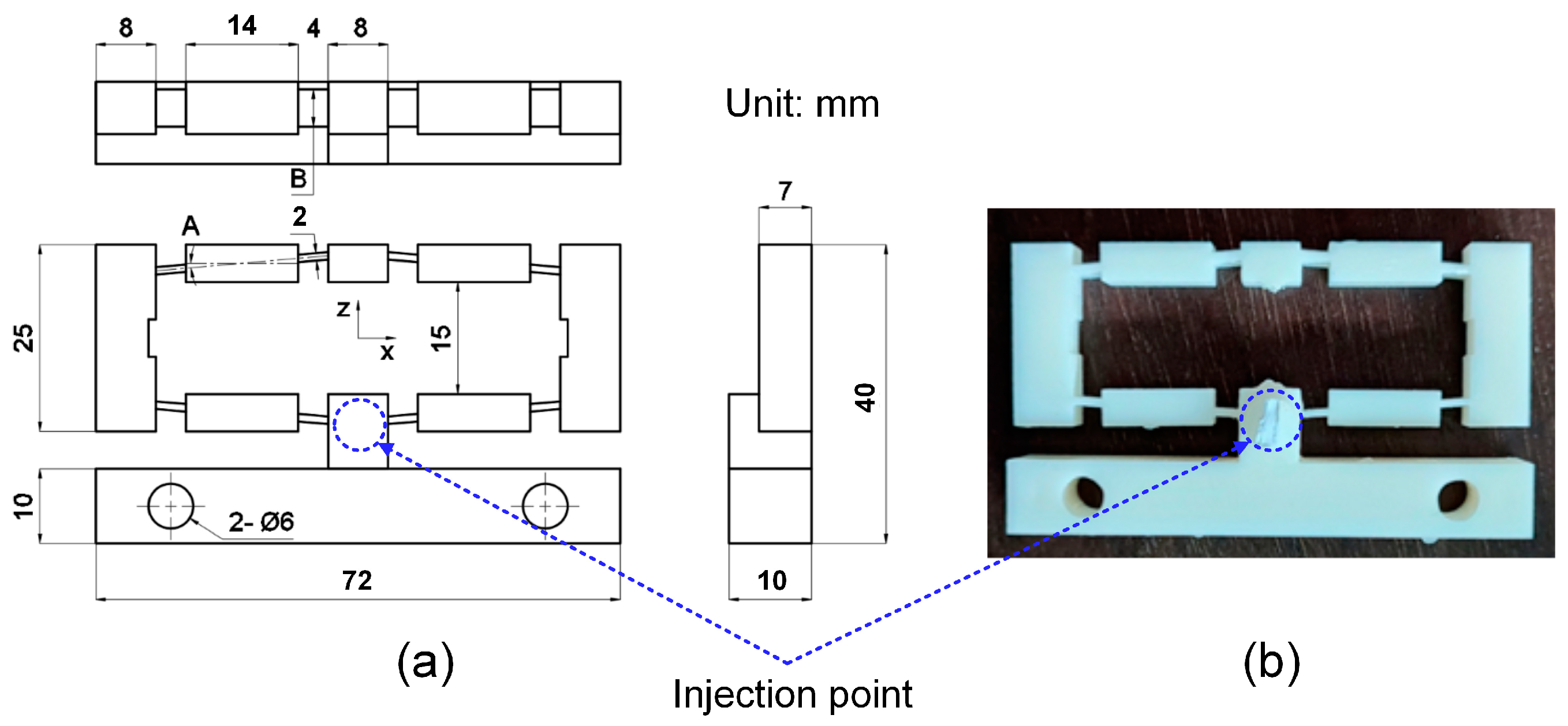
Figure 1. Plastic bridge-type flexure hinge: (a) design and (b) injected hinge [36].
Polymers 16 00394 g001
Figure 2. Compliant mechanism of the flexure hinge, fixture, and measurement device: (a) compliant mechanism, (b) fixture, and (c) measurement device setup [36].
Polymers 16 00394 g002
Figure 3. The flexure hinges at different plastics and injection conditions: (a) cooling time, (b) filling pressure, (c) filling speed, (d) filling time, (e) melt temperature, (f) packing pressure, and (g) packing time.
Polymers 16 00394 g003
Figure 4. Displacement of the ABS flexure hinge at different filling times.
Polymers 16 00394 g004
Figure 5. Displacement of the ABS flexure hinges at different filling pressures.
Polymers 16 00394 g005
Figure 6. Displacement of the ABS flexure hinges at different filling speeds.
Polymers 16 00394 g006
Figure 7. Displacement of the ABS flexure hinges at different packing times.
Polymers 16 00394 g007
Figure 8. Displacement of the ABS flexure hinges at different packing pressures.
Polymers 16 00394 g008
Figure 9. Displacement of the ABS flexure hinges at different cooling times.
Polymers 16 00394 g009
Figure 10. Displacement of the ABS flexure hinges at different melt temperatures.
Polymers 16 00394 g010
Figure 11. Displacement of PP flexure hinges at different filling times.
Polymers 16 00394 g011
Figure 12. Displacement of PP flexure hinges at different filling pressures.
Polymers 16 00394 g012
Figure 13. Displacement of PP flexure hinges at different filling speeds.
Polymers 16 00394 g013
Figure 14. Displacement of PP flexure hinges at different packing times.
Polymers 16 00394 g014
Figure 15. Displacement of PP flexure hinges at different packing pressures.
Polymers 16 00394 g015
Figure 16. Displacement of PP flexure hinges at different cooling times.
Polymers 16 00394 g016
Figure 17. Displacement of PP flexure hinges at different melt temperatures.
Polymers 16 00394 g017
Figure 18. Comparison of displacement ratio among ABS, PP, and HDPE flexure hinges.
Polymers 16 00394 g018
Table 1. Injection molding parameters of ABS hinges.
GroupFilling Time (s)Filling Pressure (bar)Packing Time (s)Packing Pressure (bar)Cooling Time (s)Melt Temperature
(°C)
Filling Speed
(%)
2
2.2
12.4
2.6410.6402421079
2.8
39
40
41
22.4420.6402421079
43
0
0.3
0.6
32.4410.9402421079
1.2
38
39
40
42.4410.6412421079
42
20
22
24
52.4410.6402621079
28
206
208
210
62.4410.6402421279
214
75
77
79
72.4410.6402421081
83
Table 2. Injection molding parameters of HDPE and PP hinges.
GroupFilling Time (s)Filling Pressure (bar)Packing Time (s)Packing Pressure (bar)Cooling Time (s)Melt Temperature
(°C)
Filling Speed
(%)
1.5
1.7
1.9
12.1270.6255421454
2.3
25
26
27
21.9280.6255421454
29
0
0.3
0.6
31.9410.9255421454
1.2
23
24
25
41.9410.6265421454
27
50
52
54
51.9410.6255621454
58
210
212
214
61.9410.6255421654
218
50
52
54
71.9410.6255421456
58
Table 3. Displacement equations of the HDPE flexure hinge.
Injection ParametersEquations
Filling timey15 = 5.0x15; R2 = 0.938
Filling pressurey16 = 4.33x16; R2 = 0.967
Filling speedy17 = 4.23x17; R2 = 0.988
Packing timey18 = 5.4x18; R2 = 0.965
Packing pressurey19 = 2.89x19; R2 = 0.952
Cooling timey20 = 2.83x20; R2 = 0.942
Melt temperaturey21 = 3.4x21; R2 = 0.993
Table 4. Amplification ratios of different flexure hinge materials.
MaterialsAmplification RatioReferences
ABS5.01–8.15This study
PP3.99–7.9This study
HDPE2.17–6.24This study
Aluminum alloys5–25Kim et al. [37]
Steel alloys16.2Na et al. [38]
Smart memory alloys2.2Maffiodo et al. [40]
Titanium alloys6.0Fiaz et al. [41]
Disclaimer/Publisher’s Note: The statements, opinions and data contained in all publications are solely those of the individual author(s) and contributor(s) and not of MDPI and/or the editor(s). MDPI and/or the editor(s) disclaim responsibility for any injury to people or property resulting from any ideas, methods, instructions or products referred to in the content.