
Material Extrusion of Wool Waste/Polycaprolactone with Improved Tensile Strength and Biodegradation


Abstract
:
1. Introduction
2. Materials and Methods
2.1. Materials
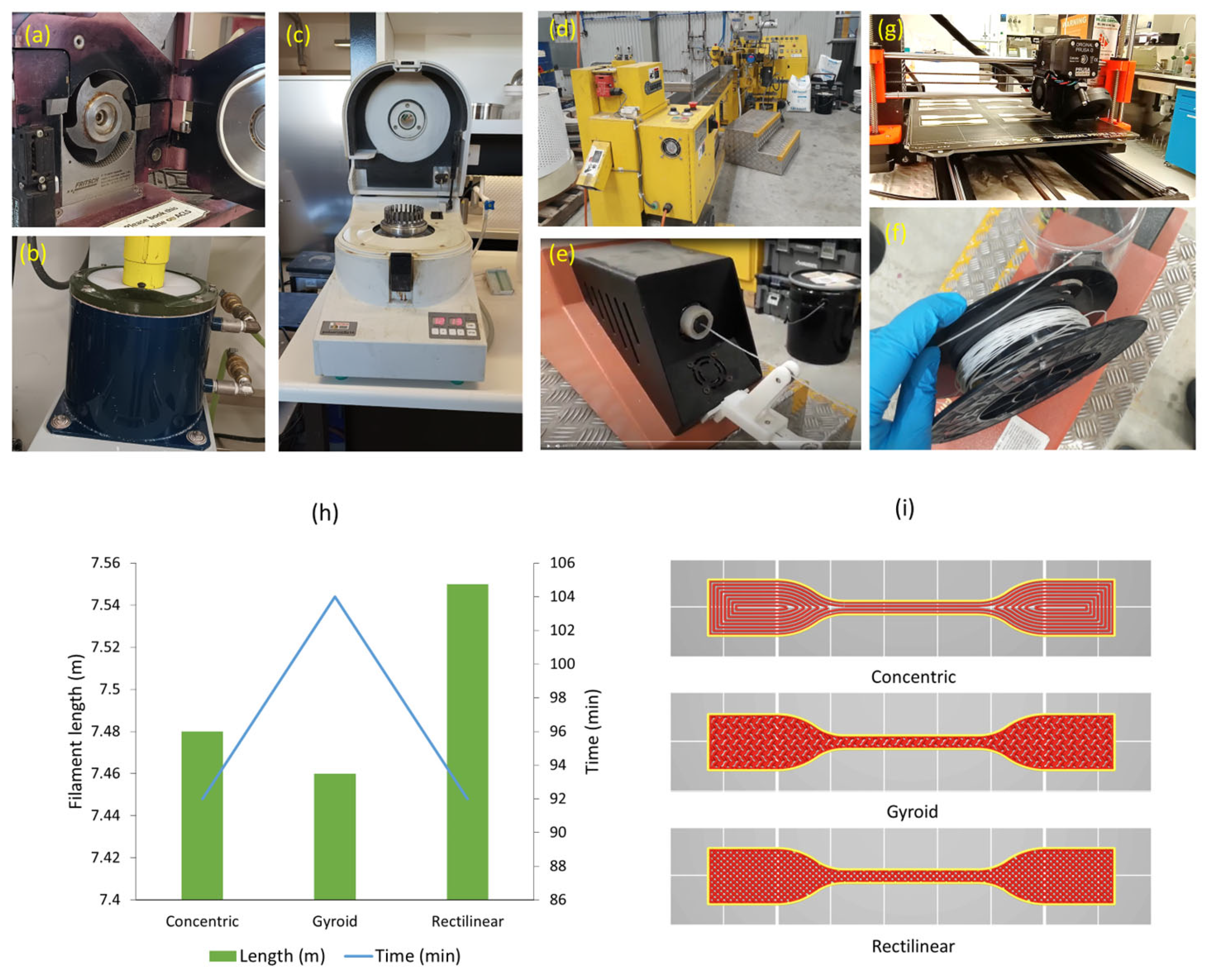
2.2. Powder Preparation
2.3. Preparation of Filaments and Printing
2.4. Characterisations
2.4.1. Rheology
2.4.2. Thermal Properties
2.4.3. Tensile Properties
2.4.4. Morphology
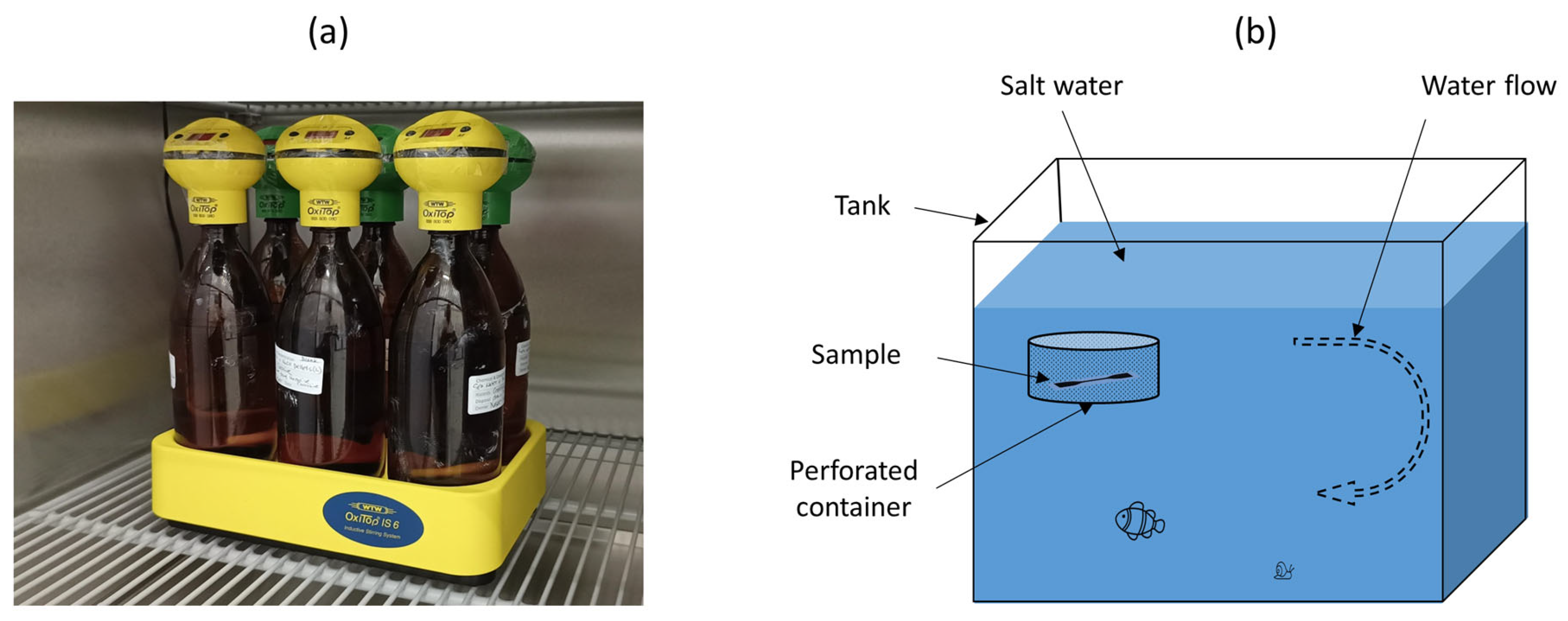
2.4.5. Biodegradation
3. Results
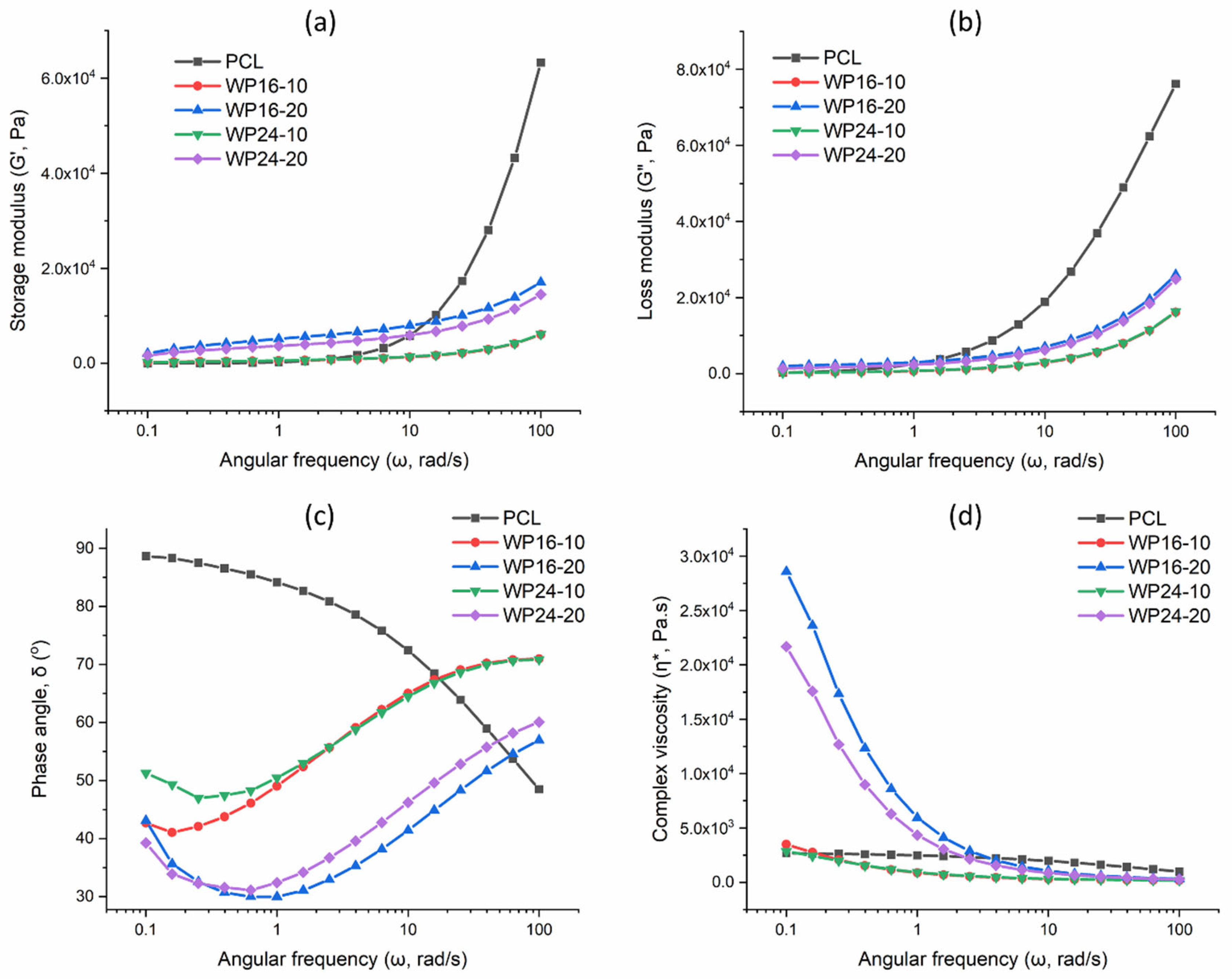
3.1. Rheology
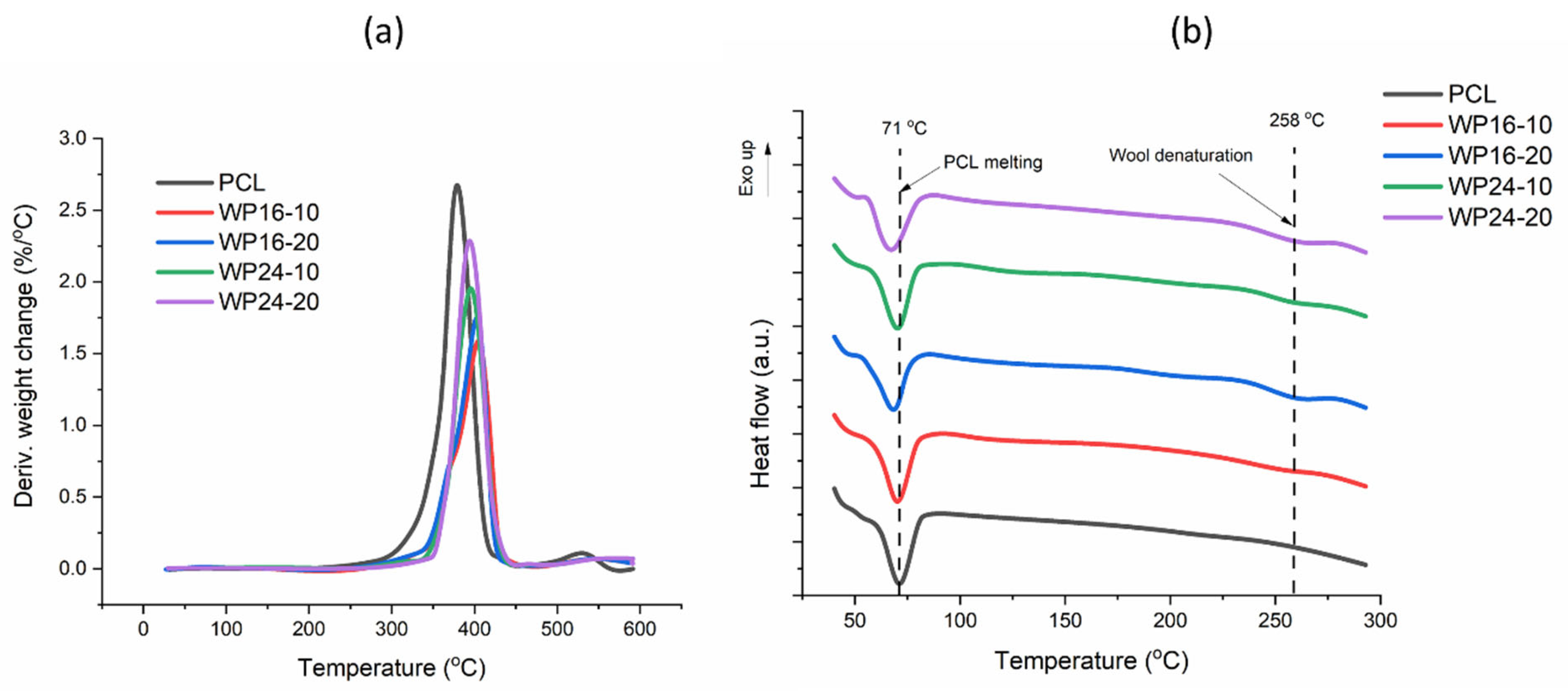
3.2. Thermal Properties
3.3. Tensile Properties
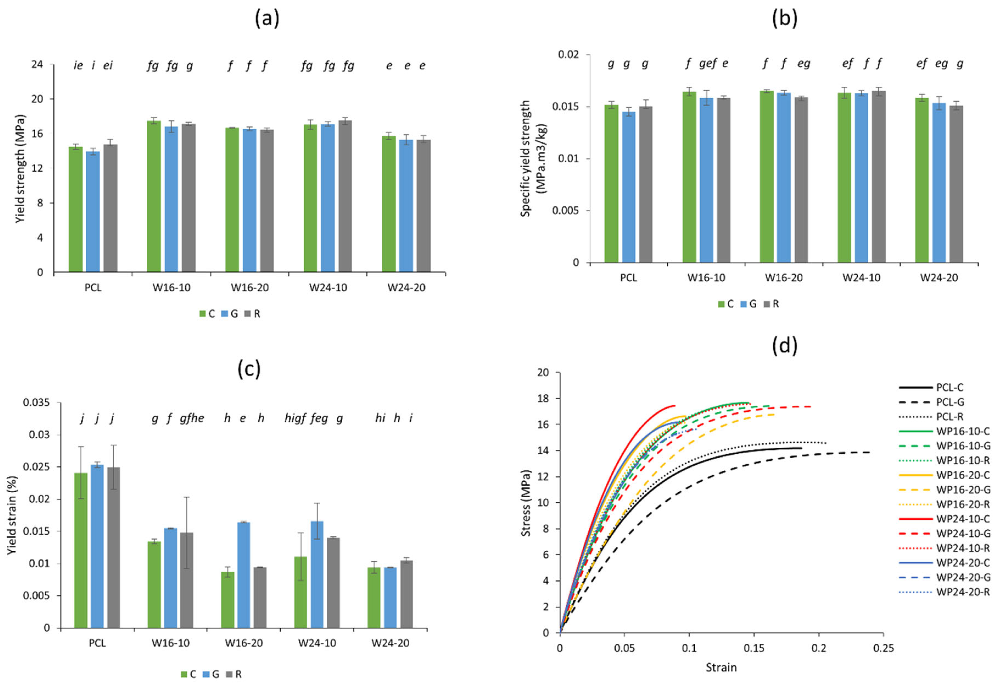
3.3.1. Impact on Yield
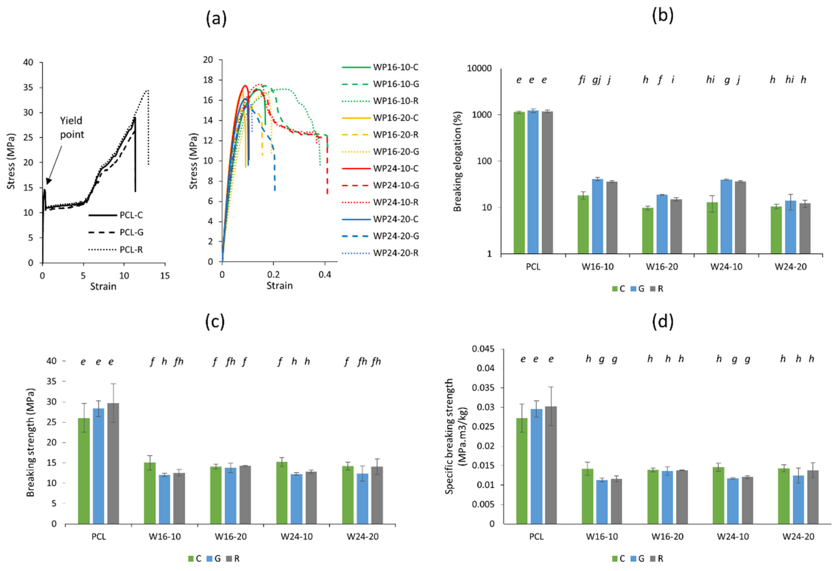
3.3.2. Impact on Ultimate Break
3.3.3. Impact on Modulus
3.4. Morphology
3.4.1. Cross-Sections of Printed Specimens
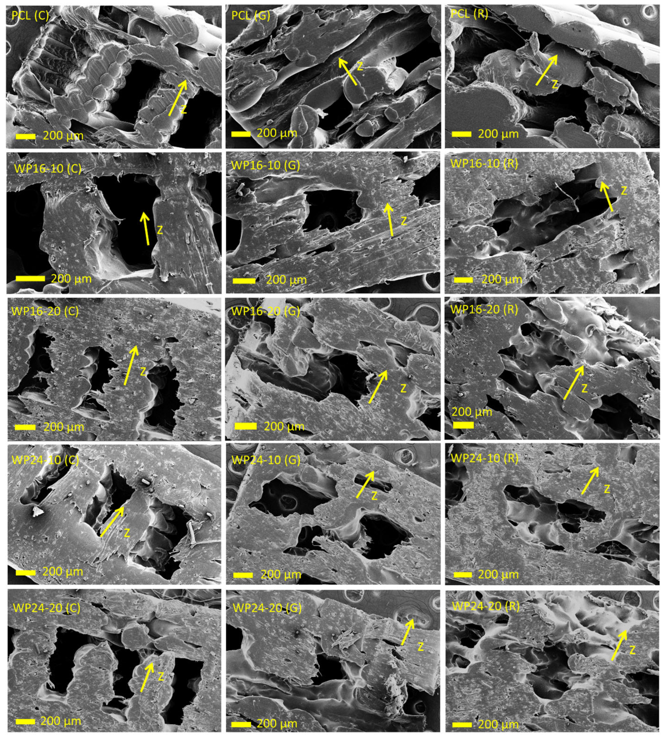
3.4.2. Cross-Sections of Fractured Specimens
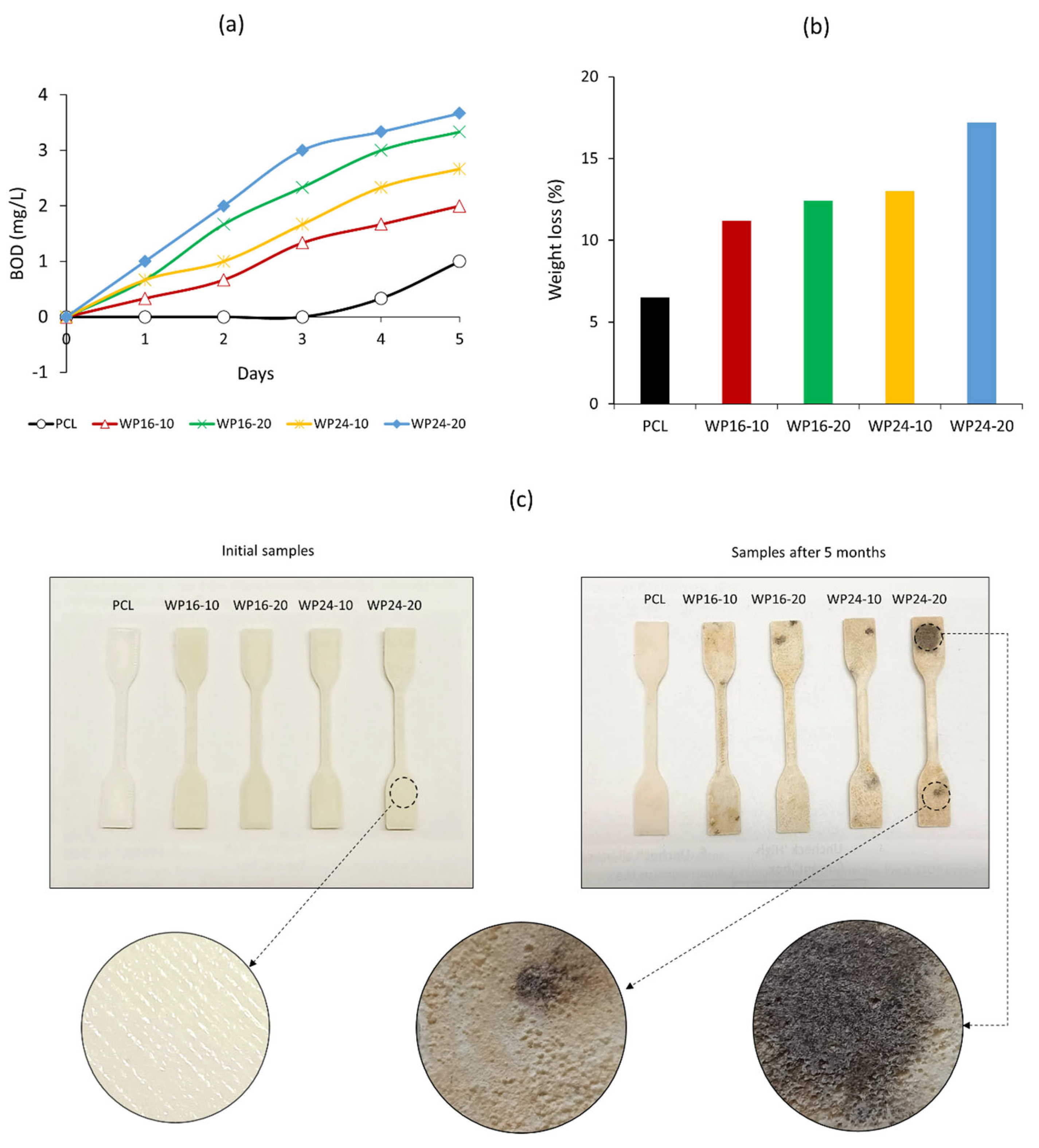
3.5. Biodegradation
4. Conclusions
- The crystallinity index of PCL decreased from 48.1% to around 45.4–45.6% and 41.1–42.6% with 10% and 20% wool, respectively.
- The melting peak position of PCL and composites remained similar for 10% wool inclusion, indicating good compatibility. A finer diameter of initial wool was found to be responsible for producing better thermal stability in the composites.
- The complex viscosity of the samples with 10/90 wool/PCL was identical to that of pure PCL at a lower angular frequency. The cross-sectional morphology of the samples showed that the disruption in the PCL matrix was more related to the loading amount, rather than fibre fineness.
- Among different infill patterns (concentric, rectilinear, gyroid), overall, the concentric infill resulted in higher average strength and lower average elongation, while gyroid infill showed higher average elongation and lower average strength, though often these differences were not significant (p > 0.05). Higher yield strength and breaking strength were consistent across the samples reinforced with 10% wool, compared to pure PCL.
- The printed materials showed an increasing trend of BOD and loss of weight in marine water due to biodegradation, corresponding to the amount of wool in the samples.
Author Contributions
Funding
Institutional Review Board Statement
Data Availability Statement
Acknowledgments
Conflicts of Interest
References
- Mazzanti, V.; Malagutti, L.; Mollica, F. FDM 3D printing of polymers containing natural fillers: A review of their mechanical properties. Polymers 2019, 11, 1094. [Google Scholar] [CrossRef]
- Balani, S.B.; Mokhtarian, H.; Salmi, T.; Coatanéa, E. An Investigation of the Influence of Viscosity and Printing Parameters on the Extrudate Geometry in the Material Extrusion Process. Polymers 2023, 15, 2202. [Google Scholar] [CrossRef] [PubMed]
- Barberi, E.; Cucinotta, F.; Raffaele, M.; Salmeri, F. A Hollowing Topology Optimization Method for Additive and Traditional Manufacturing Technologies. In Design Tools and Methods in Industrial Engineering II. ADM 2021. Lecture Notes in Mechanical Engineering; Rizzi, C., Campana, F., Bici, M., Gherardini, F., Ingrassia, T., Cicconi, P., Eds.; Springer: Cham, Germany, 2022; pp. 422–430. [Google Scholar]
- Gu, T.; Bi, H.; Sun, H.; Tang, J.; Ren, Z.; Zhou, X.; Xu, M. Design and Development of 4D-Printed Cellulose Nanofibers Reinforced Shape Memory Polymer Composites: Application for Self-deforming Plant Bionic Soft Grippers. Addit. Manuf. 2023, 70, 103544. [Google Scholar] [CrossRef]
- Jiao, Z.; Luo, B.; Xiang, S.; Ma, H.; Yu, Y.; Yang, W. 3D printing of HA/PCL composite tissue engineering scaffolds. Adv. Ind. Eng. Polym. Res. 2019, 2, 196–202. [Google Scholar] [CrossRef]
- Rodrigues-Marinho, T.; Perinka, N.; Costa, P.; Lanceros-Mendez, S. Printable lightweight polymer-based energy harvesting systems: Materials, processes and applications. Mater. Today Sustain. 2022, 21, 100292. [Google Scholar] [CrossRef]
- Ullah, M.; Wahab, A.; Khan, S.U.; Naeem, M.; ur Rehman, K.; Ali, H.; Ullah, A.; Khan, A.; Khan, N.R.; Rizg, W.Y. 3D Printing Technology: A New Approach for the Fabrication of Personalized and Customized Pharmaceuticals. Eur. Polym. J. 2023, 195, 112240. [Google Scholar] [CrossRef]
- Jain, P.K.; Jain, P.K. Use of 3D printing for home applications: A new generation concept. Mater.Today Proc. 2021, 43, 605–607. [Google Scholar] [CrossRef]
- Sam-Daliri, O.; Ghabezi, P.; Steinbach, J.; Flanagan, T.; Finnegan, W.; Mitchell, S.; Harrison, N. Experimental study on mechanical properties of material extrusion additive manufactured parts from recycled glass fibre-reinforced polypropylene composite. Compos. Sci. Technol. 2023, 241, 110125. [Google Scholar] [CrossRef]
- Al-Tamimi, A.A.; Tlija, M.; Abidi, M.H.; Anis, A.; Abd Elgawad, A.E.E. Material Extrusion of Multi-Polymer Structures Utilizing Design and Shrinkage Behaviors: A Design of Experiment Study. Polymers 2023, 15, 2683. [Google Scholar] [CrossRef]
- McNiffe, E.; Ritter, T.; Higgins, T.; Sam-Daliri, O.; Flanagan, T.; Walls, M.; Ghabezi, P.; Finnegan, W.; Mitchell, S.; Harrison, N.M. Advancements in Functionally Graded Polyether Ether Ketone Components: Design, Manufacturing, and Characterisation Using a Modified 3D Printer. Polymers 2023, 15, 2992. [Google Scholar] [CrossRef]
- Vidakis, N.; Petousis, M.; Moutsopoulou, A.; Papadakis, V.; Spiridaki, M.; Mountakis, N.; Charou, C.; Tsikritzis, D.; Maravelakis, E. Nanocomposites with Optimized Polytetrafluoroethylene Content as a Reinforcement Agent in PA12 and PLA for Material Extrusion Additive Manufacturing. Polymers 2023, 15, 2786. [Google Scholar] [CrossRef] [PubMed]
- Haque, A.N.M.A.; Naebe, M. Flexible water-resistant semi-transparent cotton gin trash/poly (vinyl alcohol) bio-plastic for packaging application: Effect of plasticisers on physicochemical properties. J. Clean. Prod. 2021, 303, 126983. [Google Scholar] [CrossRef]
- Tran, T.N.; Bayer, I.S.; Heredia-Guerrero, J.A.; Frugone, M.; Lagomarsino, M.; Maggio, F.; Athanassiou, A. Cocoa shell waste biofilaments for 3D printing applications. Macromol. Mater. Eng. 2017, 302, 1700219. [Google Scholar] [CrossRef]
- Pavon, C.; Aldas, M.; López-Martínez, J.; Ferrándiz, S. New materials for 3D-printing based on polycaprolactone with gum rosin and beeswax as additives. Polymers 2020, 12, 334. [Google Scholar] [CrossRef]
- Abdulrhman, M.; Zhakeyev, A.; Fernández-Posada, C.M.; Melchels, F.P.; Marques-Hueso, J. Routes towards manufacturing biodegradable electronics with polycaprolactone (PCL) via direct light writing and electroless plating. Flex. Print. Electron. 2022, 7, 025006. [Google Scholar] [CrossRef]
- Górecka, Ż.; Idaszek, J.; Kołbuk, D.; Choińska, E.; Chlanda, A.; Święszkowski, W. The effect of diameter of fibre on formation of hydrogen bonds and mechanical properties of 3D-printed PCL. Mater. Sci. Eng. C 2020, 114, 111072. [Google Scholar] [CrossRef]
- Lin, W.; Shen, H.; Xu, G.; Zhang, L.; Fu, J.; Deng, X. Single-layer temperature-adjusting transition method to improve the bond strength of 3D-printed PCL/PLA parts. Compos. Part A Appl. Sci. 2018, 115, 22–30. [Google Scholar] [CrossRef]
- Wang, Y.; Zhang, J.; Li, M.; Lei, M.; Wang, Y.; Wei, Q. 3D printing thermo-responsive shape memory polymer composite based on PCL/TPU blends. J. Polym. Res. 2022, 29, 243. [Google Scholar] [CrossRef]
- Hedayati, S.K.; Behravesh, A.H.; Hasannia, S.; Saed, A.B.; Akhoundi, B. 3D printed PCL scaffold reinforced with continuous biodegradable fiber yarn: A study on mechanical and cell viability properties. Polym. Test. 2020, 83, 106347. [Google Scholar] [CrossRef]
- Wang, Q.; Ye, W.; Ma, Z.; Xie, W.; Zhong, L.; Wang, Y.; Rong, Q. 3D printed PCL/β-TCP cross-scale scaffold with high-precision fiber for providing cell growth and forming bones in the pores. Mater. Sci. Eng. C 2021, 127, 112197. [Google Scholar] [CrossRef]
- Vyas, C.; Zhang, J.; Øvrebø, Ø.; Huang, B.; Roberts, I.; Setty, M.; Allardyce, B.; Haugen, H.; Rajkhowa, R.; Bartolo, P. 3D printing of silk microparticle reinforced polycaprolactone scaffolds for tissue engineering applications. Mater. Sci. Eng. C 2021, 118, 111433. [Google Scholar] [CrossRef] [PubMed]
- Manoukian, O.S.; Sardashti, N.; Stedman, T.; Gailiunas, K.; Ojha, A.; Penalosa, A.; Mancuso, C.; Hobert, M.; Kumbar, S.G. Biomaterials for tissue engineering and regenerative medicine. In Encyclopedia of Biomedical Engineering; Narayan, R., Ed.; Elsevier: Plzen, Czech Republic, 2019; pp. 462–482. [Google Scholar]
- Ilyas, R.; Zuhri, M.; Norrrahim, M.N.F.; Misenan, M.S.M.; Jenol, M.A.; Samsudin, S.A.; Nurazzi, N.; Asyraf, M.; Supian, A.; Bangar, S.P. Natural fiber-reinforced polycaprolactone green and hybrid biocomposites for various advanced applications. Polymers 2022, 14, 182. [Google Scholar] [CrossRef] [PubMed]
- Nitz, H.; Semke, H.; Landers, R.; Mülhaupt, R. Reactive extrusion of polycaprolactone compounds containing wood flour and lignin. J. Appl. Polym. Sci. 2001, 81, 1972–1984. [Google Scholar] [CrossRef]
- Lee, S.H.; Ohkita, T. Mechanical and thermal flow properties of wood flour–biodegradable polymer composites. J. Appl. Polym. Sci. 2003, 90, 1900–1905. [Google Scholar] [CrossRef]
- IWTO. World Sheep Numbers & Wool Production: IWTO Market Information Ed.17. Available online: https://iwto.org/wp-content/uploads/2022/04/IWTO-Market-Information-Sample-Edition-17.pdf (accessed on 13 October 2022).
- Textile Exchange. Preferred Fiber & Materials: Market Report 2021. Available online: https://textileexchange.org/wp-content/uploads/2021/08/Textile-Exchange_Preferred-Fiber-and-Materials-Market-Report_2021.pdf (accessed on 13 October 2022).
- Haque, A.N.M.A.; Naebe, M.; Mielewski, D.; Kiziltas, A. Thermally stable micro-sized silica-modified wool powder from one-step alkaline treatment. Powder Tech. 2022, 404, 117517. [Google Scholar] [CrossRef]
- Haque, A.N.M.A.; Naebe, M. Waste Wool Powder for Promoting Plant Growth by Moisture Retention. Sustainability 2022, 14, 12267. [Google Scholar] [CrossRef]
- Li, Y.-B.; Liu, H.-H.; Wang, X.-C.; Zhang, X.-X. Fabrication and performance of wool keratin–functionalized graphene oxide composite fibers. Mater. Today Sustain. 2019, 3, 100006. [Google Scholar] [CrossRef]
- Naebe, M.; Cookson, P.G.; Rippon, J.A.; Wang, X.G. Effects of leveling agent on the uptake of reactive dyes by untreated and plasma-treated wool. Text. Res. J. 2010, 80, 611–622. [Google Scholar] [CrossRef]
- Marti, M.; Ramirez, R.; Barba, C.; Coderch, L.; Parra, J. Influence of internal lipid on dyeing of wool fibers. Text. Res. J. 2010, 80, 365–373. [Google Scholar] [CrossRef]
- Haque, A.N.M.A.; Naebe, M.; Mielewski, D.; Kiziltas, A. Waste wool/polycaprolactone filament towards sustainable use in 3D printing. J. Clean. Prod. 2023, 386, 135781. [Google Scholar] [CrossRef]
- Akhoundi, B.; Behravesh, A.H. Effect of filling pattern on the tensile and flexural mechanical properties of FDM 3D printed products. Exp. Mech. 2019, 59, 883–897. [Google Scholar] [CrossRef]
- Prusa Research. Infill Patterns. Available online: https://help.prusa3d.com/article/infill-patterns_177130 (accessed on 17 April 2023).
- ISO 527-2; Plastics—Determination of tensile properties—Part 2: Test conditions for moulding and extrusion plastics. ISO: Geneva, Switzerland, 2012.
- Patrício, T.; Bártolo, P. Thermal stability of PCL/PLA blends produced by physical blending process. Procedia Eng. 2013, 59, 292–297. [Google Scholar] [CrossRef]
- BS EN 1899-2:1998; Water Quality: Determination of Biochemical Oxygen Demand after n Days (BODn) Method for Undiluted Samples. European Standards: Brussels, Belgium, 1998.
- Bek, M.; Gonzalez-Gutierrez, J.; Kukla, C.; Črešnar, K.P.; Maroh, B.; Slemenik Perše, L. Rheological behaviour of highly filled materials for injection moulding and additive manufacturing: Effect of particle material and loading. Appl. Sci. 2020, 10, 7993. [Google Scholar] [CrossRef]
- Mei, M.W.S. Physico-Chemical Characterisation and Functionality of the Polysaccharide Extracted from the New Zealand Black Tree Fern, Cyathea Medullaris (Mamaku); Massey University: Palmerston North, New Zealand, 2015. [Google Scholar]
- Huson, M.G. Properties of wool. In Handbook of Properties of Textile and Technical Fibres; Bunsell, A.R., Ed.; Woodhead Publishing: Sawston, UK; Elsevier: Amsterdam, The Netherlands, 2018; pp. 59–103. [Google Scholar]
- Koenig, M.; Huang, S. Biodegradable blends and composites of polycaprolactone and starch derivatives. Polymer 1995, 36, 1877–1882. [Google Scholar] [CrossRef]
- Puri, P.; Yang, V. Effect of voids and pressure on melting of nano-particulate and bulk aluminum. J. Nanopart. Res. 2009, 11, 1117–1127. [Google Scholar] [CrossRef]
- Cavalcante, M.P.; Toledo, A.L.; Rodrigues, E.J.; Neto, R.P.; Tavares, M.I. Correlation between traditional techniques and TD-NMR to determine the morphology of PHB/PCL blends. Polym. Test. 2017, 58, 159–165. [Google Scholar] [CrossRef]
- Zhu, H.; Li, R.; Wu, X.; Chen, K.; Che, J. Controllable fabrication and characterization of hydrophilic PCL/wool keratin nanonets by electronetting. Eur. Polym. J. 2017, 86, 154–161. [Google Scholar] [CrossRef]
- D638-14; Standard Test Method for Tensile Properties of Plastics. ASTM International: West Conshohocken, PA, USA, 2015.
- Perstorp. Properties & Processing of Capa® Thermoplastics. Available online: http://www.rapstrap.com/TDS-CAPA6500.pdf (accessed on 22 May 2023).
- Hussain, A.; Podgursky, V.; Goljandin, D.; Antonov, M.; Viljus, M.; Krasnou, I. Sustainable fabrication of polypropylene-postconsumer cotton composite materials: Circularity, characterization, mechanical testing, and tribology. Mater. Today Sustain. 2023, 22, 100344. [Google Scholar] [CrossRef]
- Mahdi, E.; Dean, A. The effect of filler content on the tensile behavior of polypropylene/cotton fiber and poly (vinyl chloride)/cotton fiber composites. Materials 2020, 13, 753. [Google Scholar] [CrossRef]
- Ali, S.A. Mechanical and thermal properties of promising polymer composites for food packaging applications. IOP Conf. Ser. Mater. Sci. Eng. 2016, 137, 012035. [Google Scholar] [CrossRef]
- Khan, S.; Zakaria, H.; Chong, Y.; Saad, M.; Basaruddin, K. Effect of infill on tensile and flexural strength of 3D printed PLA parts. IOP Conf. Ser. Mater. Sci. Eng. 2018, 429, 012101. [Google Scholar] [CrossRef]
- Liang, J.-Z.; Duan, D.-R.; Tang, C.-Y.; Tsui, C.-P.; Chen, D.-Z. Tensile properties of PLLA/PCL composites filled with nanometer calcium carbonate. Polym. Test. 2013, 32, 617–621. [Google Scholar] [CrossRef]
- Ogunsona, E.; Codou, A.; Misra, M.; Mohanty, A. A critical review on the fabrication processes and performance of polyamide biocomposites from a biofiller perspective. Mater. Today Sustain. 2019, 5, 100014. [Google Scholar] [CrossRef]
- Dhakal, H.; Bourmaud, A.; Berzin, F.; Almansour, F.; Zhang, Z.; Shah, D.U.; Beaugrand, J. Mechanical properties of leaf sheath date palm fibre waste biomass reinforced polycaprolactone (PCL) biocomposites. Ind. Crops Prod. 2018, 126, 394–402. [Google Scholar] [CrossRef]
- Silva, C.; Pais, A.I.; Caldas, G.; Gouveia, B.P.; Alves, J.L.; Belinha, J. Study on 3D printing of gyroid-based structures for superior structural behaviour. Prog. Addit. Manuf. 2021, 6, 689–703. [Google Scholar] [CrossRef]
- Nakayama, A.; Yamano, N.; Kawasaki, N. Biodegradation in seawater of aliphatic polyesters. Polym. Degrad. Stab. 2019, 166, 290–299. [Google Scholar] [CrossRef]


| Wool Fineness (μm) | Wool (%) | PCL (%) | Name |
|---|---|---|---|
| - | 0 | 100 | PCL |
| 16 | 10 | 90 | WP16-10 |
| 16 | 20 | 80 | WP16-20 |
| 24 | 10 | 90 | WP24-10 |
| 24 | 20 | 80 | WP24-20 |
| PCL | WP16-10 | WP16-20 | WP24-10 | WP24-20 | ||
|---|---|---|---|---|---|---|
| Degradation (270–450 °C) | Peak (°C) | 379 | 404 | 404 | 394 | 394 |
| Weight loss (%) | 93.3 | 86.8 | 87.1 | 91.5 | 91.9 | |
| Residue (%) | 600 °C | 0.09 | 1.7 | 1.9 | 1.5 | 1.8 |
| Evaporation | Peak (°C) | 70.9 | 70.3 | 68.4 | 70.2 | 67.5 |
| Enthalpy (J/g) | 66.9 | 63.4 | 59.2 | 63.1 | 57.1 | |
| Crystallinity index (%) | 48.1 | 45.6 | 42.6 | 45.4 | 41.1 | |
| Denaturation | Peak (°C) | - | 258.8 | 258.3 | 258.5 | 258.1 |
| Enthalpy (J/g) | - | 0.47 | 2.51 | 0.49 | 2.66 |
Disclaimer/Publisher’s Note: The statements, opinions and data contained in all publications are solely those of the individual author(s) and contributor(s) and not of MDPI and/or the editor(s). MDPI and/or the editor(s) disclaim responsibility for any injury to people or property resulting from any ideas, methods, instructions or products referred to in the content. |
© 2023 by the authors. Licensee MDPI, Basel, Switzerland. This article is an open access article distributed under the terms and conditions of the Creative Commons Attribution (CC BY) license (https://creativecommons.org/licenses/by/4.0/).
Share and Cite
Haque, A.N.M.A.; Naebe, M. Material Extrusion of Wool Waste/Polycaprolactone with Improved Tensile Strength and Biodegradation. Polymers 2023, 15, 3439. https://doi.org/10.3390/polym15163439
Haque ANMA, Naebe M. Material Extrusion of Wool Waste/Polycaprolactone with Improved Tensile Strength and Biodegradation. Polymers. 2023; 15(16):3439. https://doi.org/10.3390/polym15163439
Chicago/Turabian StyleHaque, Abu Naser Md Ahsanul, and Maryam Naebe. 2023. "Material Extrusion of Wool Waste/Polycaprolactone with Improved Tensile Strength and Biodegradation" Polymers 15, no. 16: 3439. https://doi.org/10.3390/polym15163439
APA StyleHaque, A. N. M. A., & Naebe, M. (2023). Material Extrusion of Wool Waste/Polycaprolactone with Improved Tensile Strength and Biodegradation. Polymers, 15(16), 3439. https://doi.org/10.3390/polym15163439