


Rolled Dielectric Elastomer Antagonistic Actuators for Biomimetic Underwater Robots


Abstract
1. Introduction
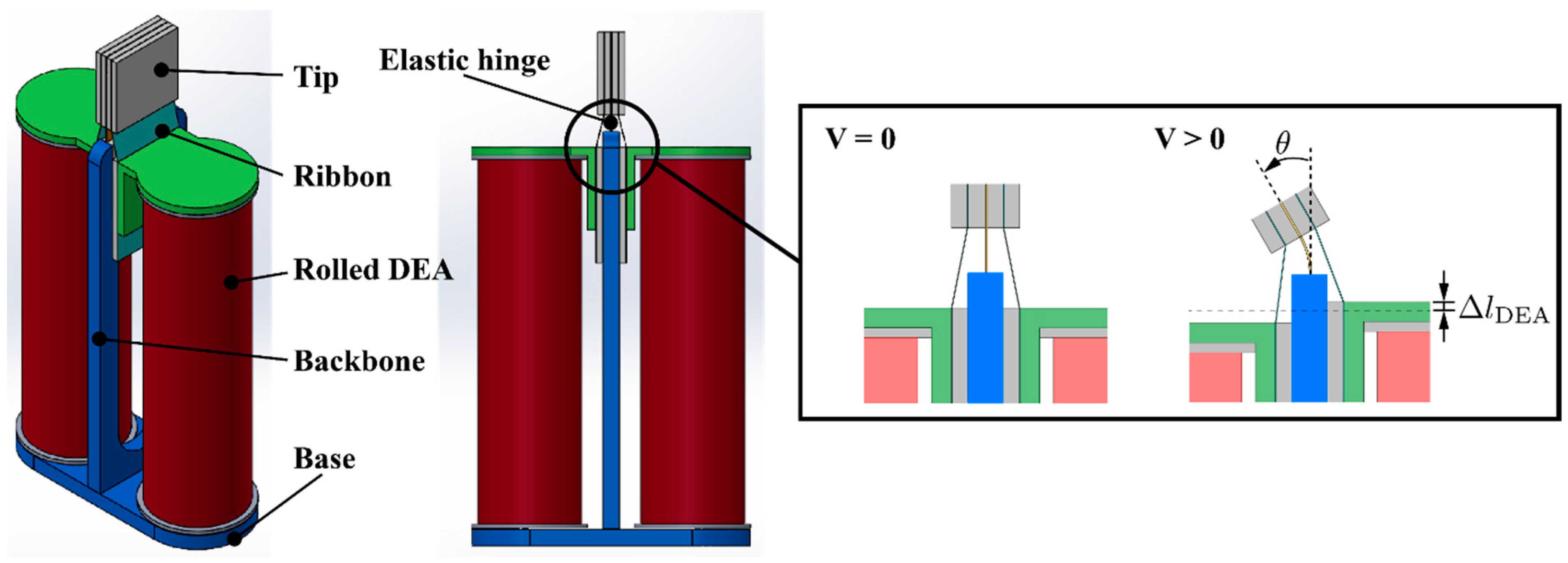
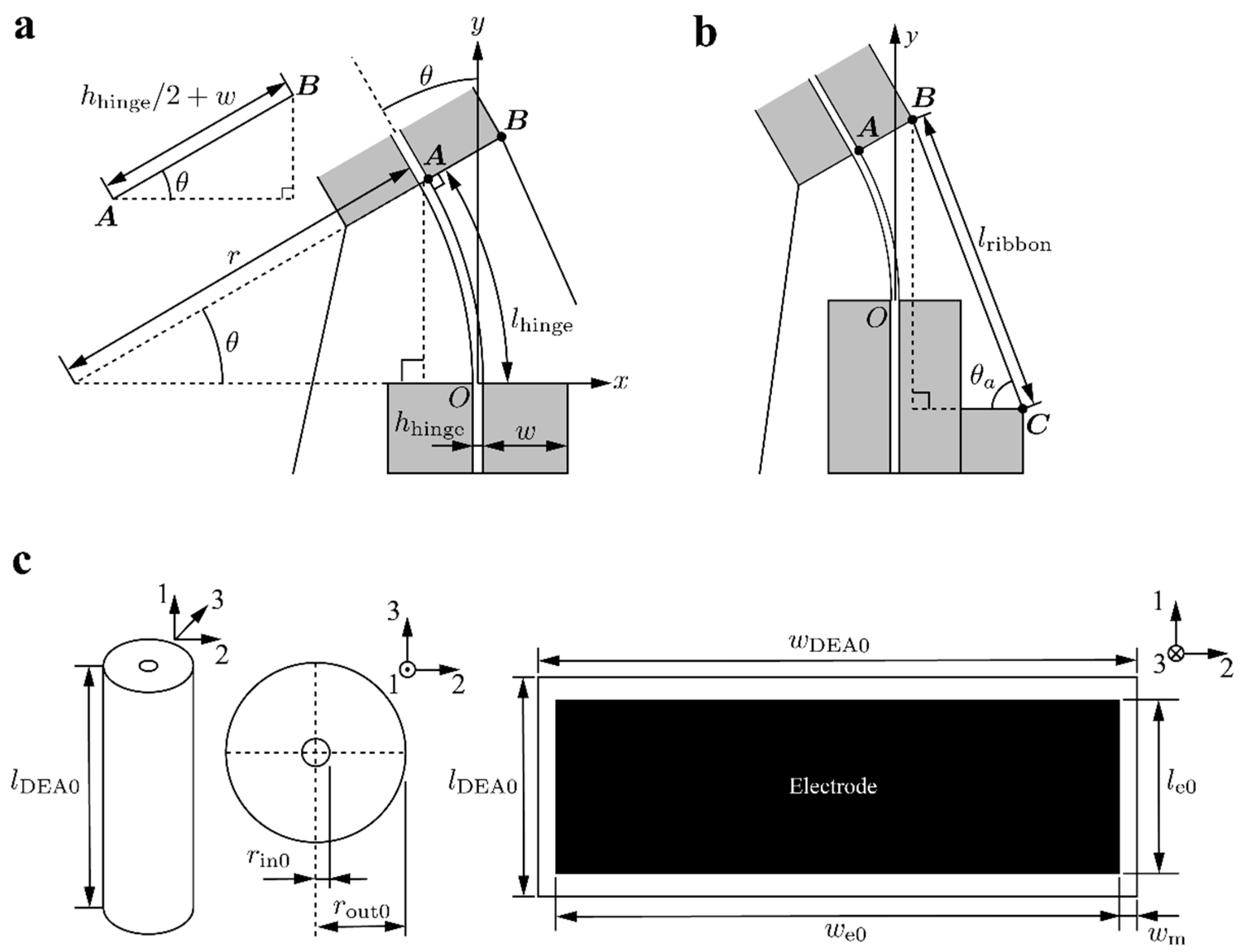
2. Working Principle and Model
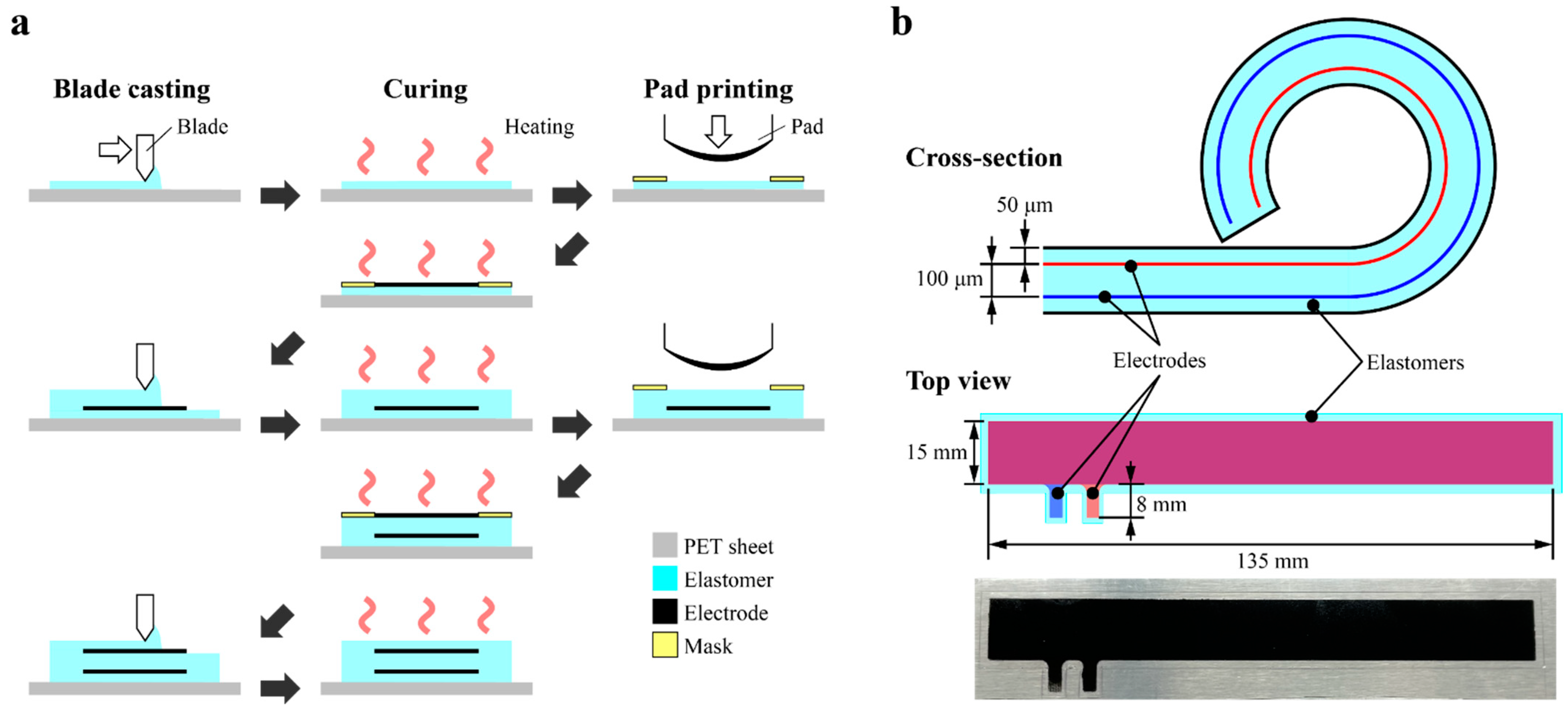
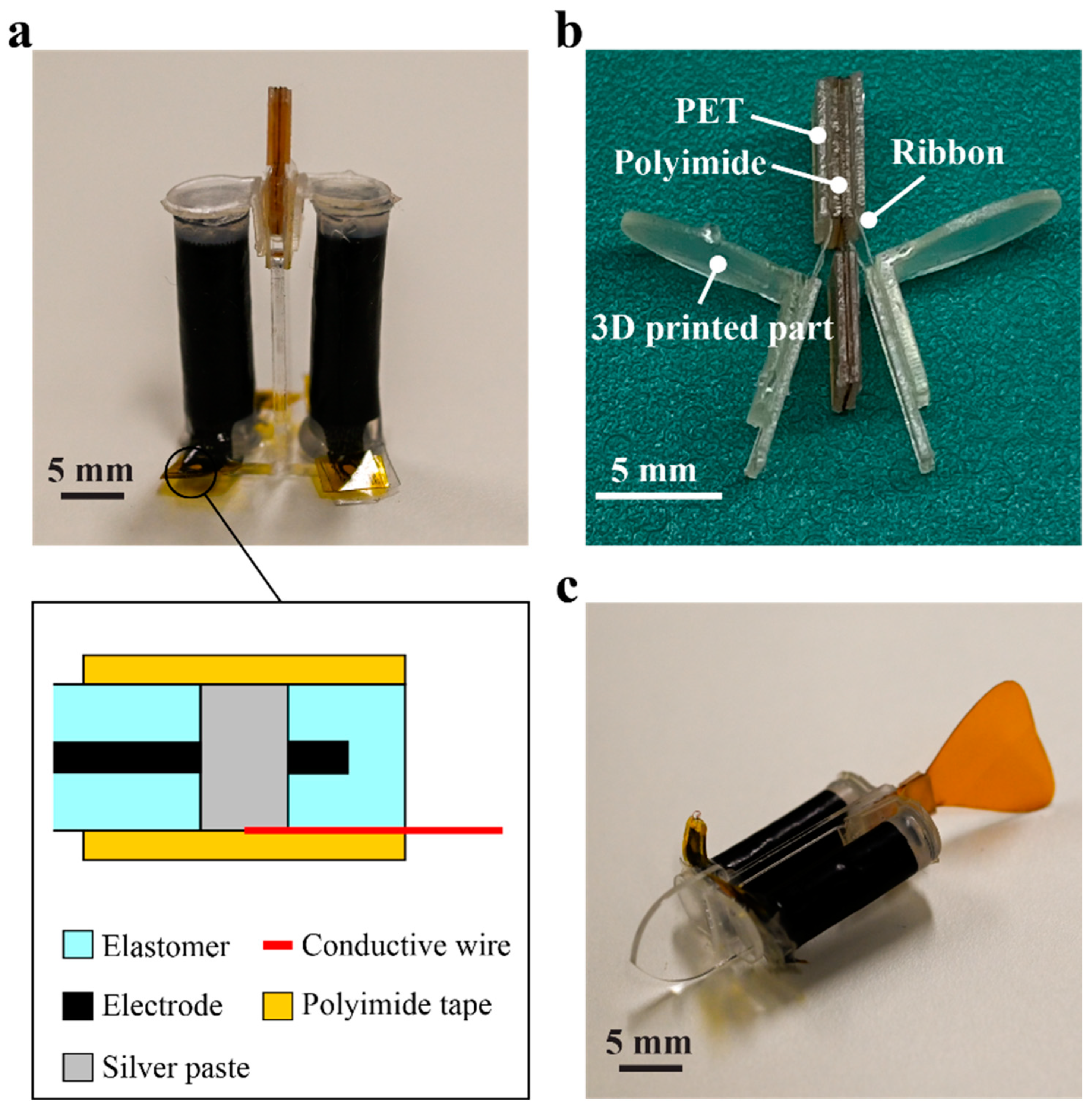
3. Fabrication
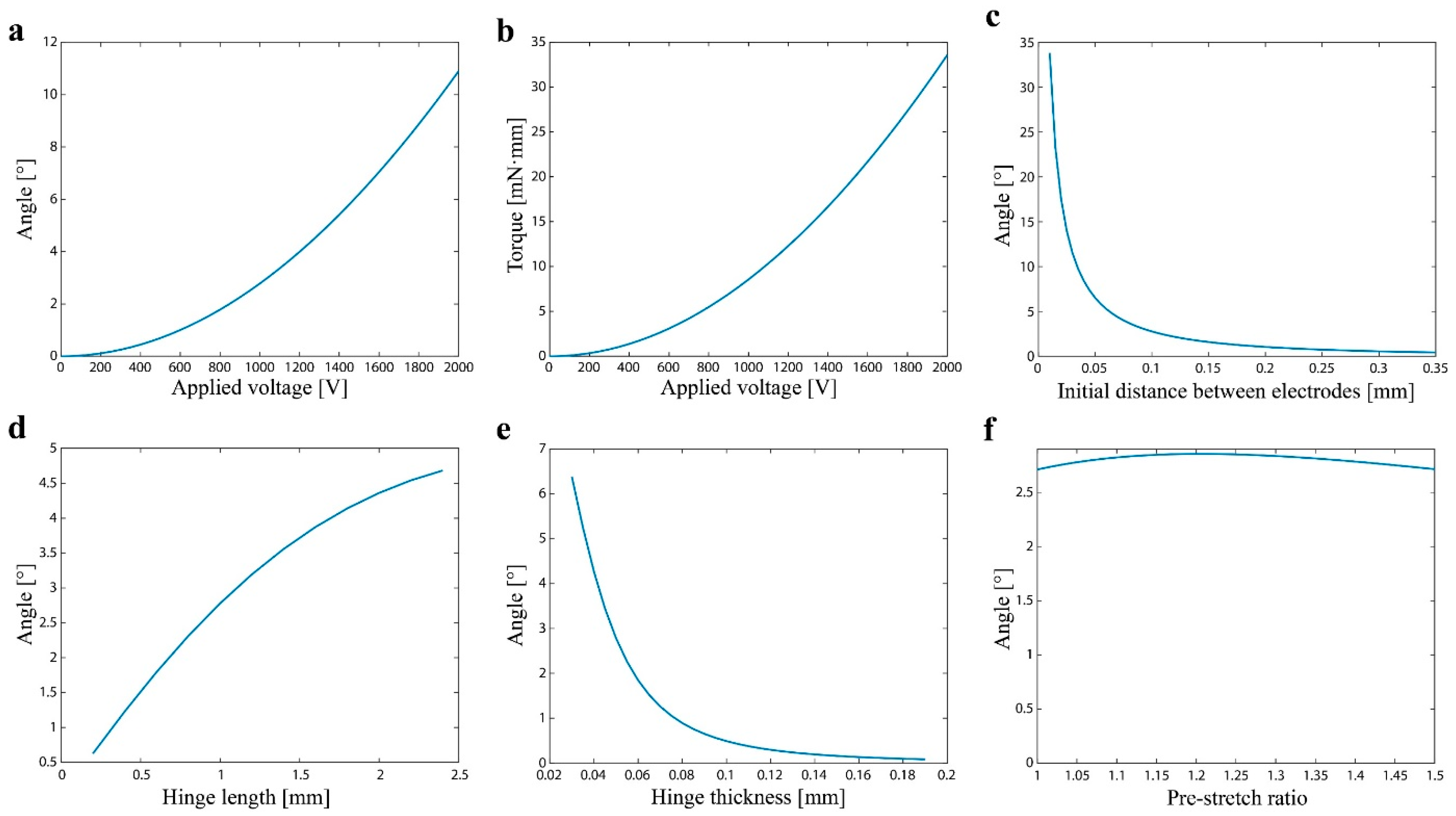
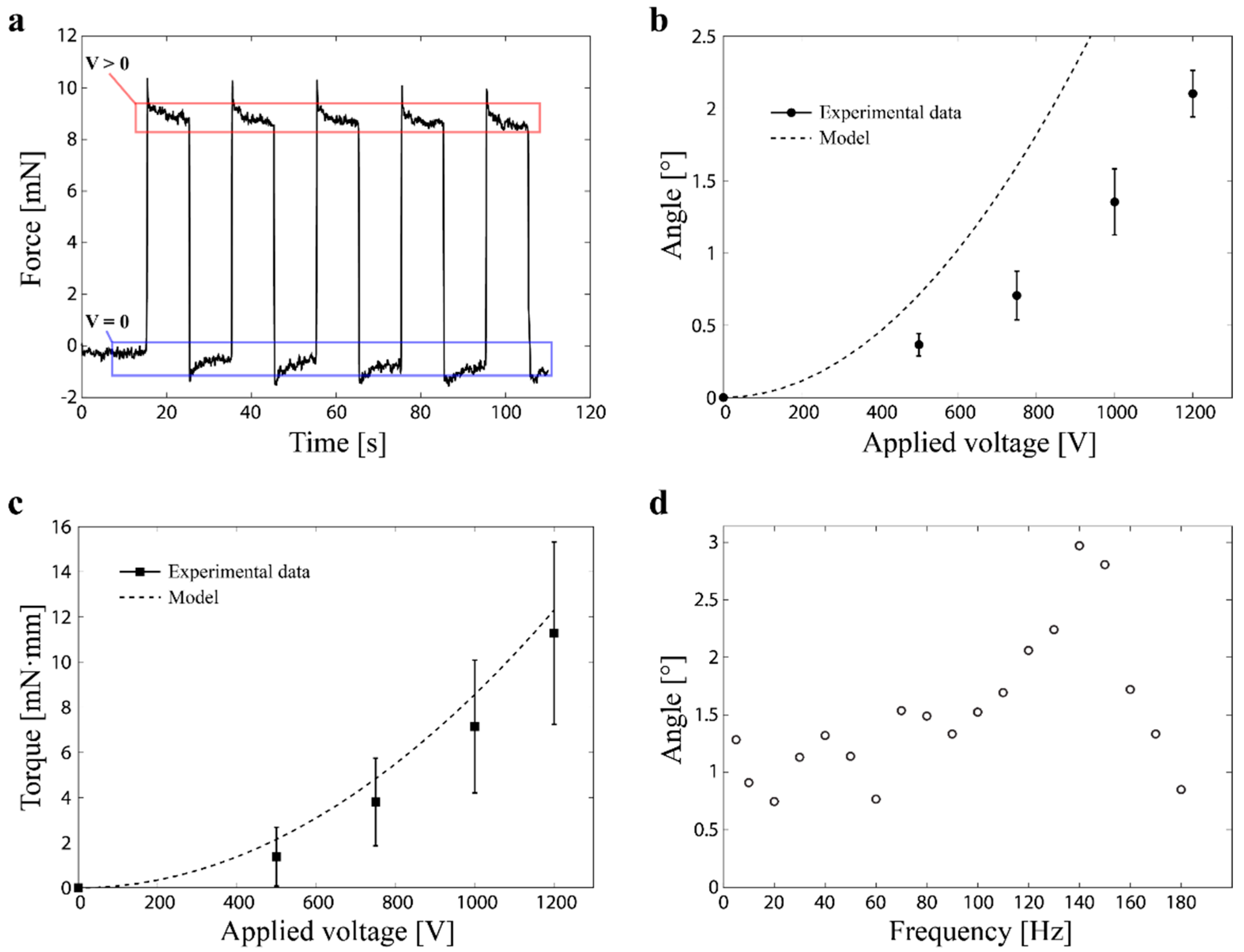
4. Characterization
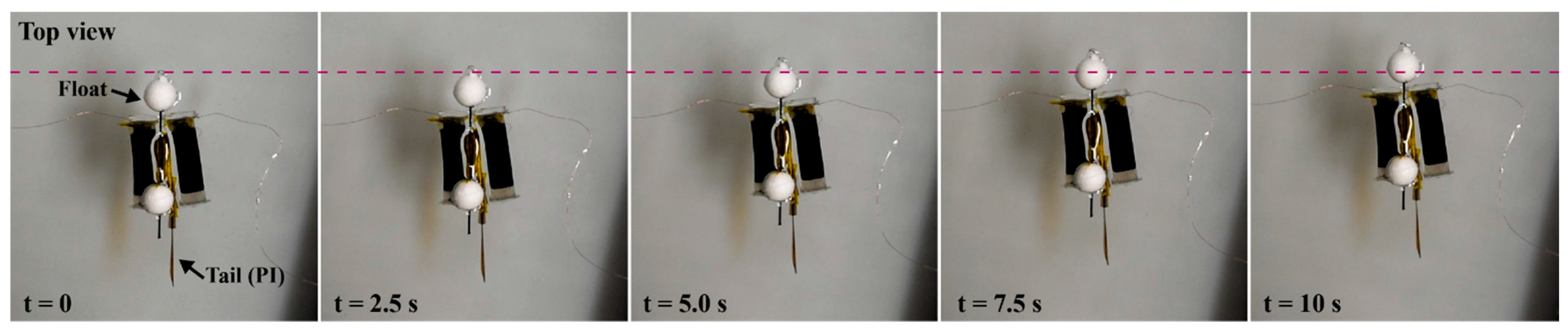
5. Swimming Demonstration
6. Conclusions
Supplementary Materials
Author Contributions
Funding
Institutional Review Board Statement
Informed Consent Statement
Data Availability Statement
Acknowledgments
Conflicts of Interest
References
- Guo, Y.; Liu, L.; Liu, Y.; Leng, J. Review of Dielectric Elastomer Actuators and Their Applications in Soft Robots. Adv. Intell. Syst. 2021, 3, 2000282. [Google Scholar] [CrossRef]
- Gu, G.-Y.; Zhu, J.; Zhu, L.-M.; Zhu, X. A survey on dielectric elastomer actuators for soft robots. Bioinspir. Biomim. 2017, 12, 011003. [Google Scholar] [CrossRef] [PubMed]
- Gupta, U.; Qin, L.; Wang, Y.; Godaba, H.; Zhu, J. Soft robots based on dielectric elastomer actuators: A review. Smart Mater. Struct. 2019, 28, 103002. [Google Scholar] [CrossRef]
- Youn, J.H.; Jeong, S.M.; Hwang, G.; Kim, H.; Hyeon, K.; Park, J.; Kyung, K.U. Dielectric elastomer actuator for soft robotics applications and challenges. Appl. Sci. 2020, 10, 640. [Google Scholar] [CrossRef]
- Trivedi, D.; Rahn, C.D.; Kier, W.M.; Walker, I.D. Soft robotics: Biological inspiration, state of the art, and future research. Appl. Bionics Biomech. 2008, 5, 99–117. [Google Scholar] [CrossRef]
- Rus, D.; Tolley, M.T. Design, fabrication and control of soft robots. Nature 2015, 521, 467–475. [Google Scholar] [CrossRef] [PubMed]
- Shintake, J.; Cacucciolo, V.; Floreano, D.; Shea, H. Soft Robotic Grippers. Adv. Mater. 2018, 30, 1707035. [Google Scholar] [CrossRef]
- Rich, S.I.; Wood, R.J.; Majidi, C. Untethered soft robotics. Nat. Electron. 2018, 1, 102–112. [Google Scholar] [CrossRef]
- Anderson, I.A.; Gisby, T.A.; McKay, T.G.; O’Brien, B.M.; Calius, E.P. Multi-functional dielectric elastomer artificial muscles for soft and smart machines. J. Appl. Phys. 2012, 112, 041101. [Google Scholar] [CrossRef]
- Rosset, S.; Shea, H.R. Flexible and stretchable electrodes for dielectric elastomer actuators. Appl. Phys. A 2013, 110, 281–307. [Google Scholar] [CrossRef]
- Brochu, P.; Pei, Q. Advances in Dielectric Elastomers for Actuators and Artificial Muscles. Macromol. Rapid Commun. 2010, 31, 10–36. [Google Scholar] [CrossRef]
- Shintake, J.; Cacucciolo, V.; Shea, H.; Floreano, D. Soft Biomimetic Fish Robot Made of Dielectric Elastomer Actuators. Soft Robot. 2018, 5, 466–474. [Google Scholar] [CrossRef] [PubMed]
- Berlinger, F.; Duduta, M.; Gloria, H.; Clarke, D.; Nagpal, R.; Wood, R. A Modular Dielectric Elastomer Actuator to Drive Miniature Autonomous Underwater Vehicles. In Proceedings of the 2018 IEEE International Conference on Robotics and Automation (ICRA), Brisbane, Australia, 21–25 May 2018; pp. 3429–3435. [Google Scholar]
- Godaba, H.; Li, J.; Wang, Y.; Zhu, J. A Soft Jellyfish Robot Driven by a Dielectric Elastomer Actuator. IEEE Robot. Autom. Lett. 2016, 1, 624–631. [Google Scholar] [CrossRef]
- Shintake, J.; Shea, H.; Floreano, D. Biomimetic underwater robots based on dielectric elastomer actuators. In Proceedings of the 2016 IEEE/RSJ International Conference on Intelligent Robots and Systems, Daejeon, Korea, 9–14 October 2016; pp. 4957–4962. [Google Scholar] [CrossRef]
- Cheng, T.; Li, G.; Liang, Y.; Zhang, M.; Liu, B.; Wong, T.W.; Forman, J.; Chen, M.; Wang, G.; Tao, Y.; et al. Untethered soft robotic jellyfish. Smart Mater. Struct. 2019, 28, 015019. [Google Scholar] [CrossRef]
- Christianson, C.; Bayag, C.; Li, G.; Jadhav, S.; Giri, A.; Agba, C.; Li, T.; Tolley, M.T. Jellyfish-Inspired Soft Robot Driven by Fluid Electrode Dielectric Organic Robotic Actuators. Front. Robot. AI 2019, 6, 126. [Google Scholar] [CrossRef] [PubMed]
- Shimizu, K.; Nagai, T.; Shintake, J. Dielectric Elastomer Fiber Actuators with Aqueous Electrode. Polymers 2021, 13, 4310. [Google Scholar] [CrossRef] [PubMed]
- Li, T.; Li, G.; Liang, Y.; Cheng, T.; Dai, J.; Yang, X.; Liu, B.; Zeng, Z.; Huang, Z.; Luo, Y.; et al. Fast-moving soft electronic fish. Sci. Adv. 2017, 3, e1602045. [Google Scholar] [CrossRef]
- Christianson, C.; Goldberg, N.N.; Deheyn, D.D.; Cai, S.; Tolley, M.T. Translucent soft robots driven by frameless fluid electrode dielectric elastomer actuators. Sci. Robot. 2018, 3, eaat1893. [Google Scholar] [CrossRef] [PubMed]
- Li, G.; Shintake, J.; Hayashibe, M. Deep Reinforcement Learning Framework for Underwater Locomotion of Soft Robot. In Proceedings of the 2021 IEEE International Conference on Robotics and Automation (ICRA), IEEE, Xi’an, China, 30 May–5 June 2021; pp. 12033–12039. [Google Scholar]
- Tang, C.; Ma, W.; Li, B.; Jin, M.; Chen, H. Cephalopod-Inspired Swimming Robot Using Dielectric Elastomer Synthetic Jet Actuator. Adv. Eng. Mater. 2020, 22, 1901130. [Google Scholar] [CrossRef]
- Tang, Y.; Qin, L.; Li, X.; Chew, C.-M.; Zhu, J. A frog-inspired swimming robot based on dielectric elastomer actuators. In Proceedings of the 2017 IEEE/RSJ International Conference on Intelligent Robots and Systems (IROS), Vancouver, BC, Canada, 24–28 September 2017; pp. 2403–2408. [Google Scholar]
- Rajamani, A.; Grissom, M.; Rahn, C.; Ma, Y.; Zhang, Q. Wound roll dielectric elastomer actuators: Fabrication, analysis and experiments. In Proceedings of the 2005 IEEE/RSJ International Conference on Intelligent Robots and Systems, Edmonton, AB, Canada, 2–6 August 2005; Volume 13, pp. 1520–1525. [Google Scholar]
- Sarban, R.; Jones, R.W.; Mace, B.R.; Rustighi, E. A tubular dielectric elastomer actuator: Fabrication, characterization and active vibration isolation. Mech. Syst. Signal Process. 2011, 25, 2879–2891. [Google Scholar] [CrossRef]
- Kunze, J.; Prechtl, J.; Bruch, D.; Fasolt, B.; Nalbach, S.; Motzki, P.; Seelecke, S.; Rizzello, G. Design, Manufacturing, and Characterization of Thin, Core-Free, Rolled Dielectric Elastomer Actuators. Actuators 2021, 10, 69. [Google Scholar] [CrossRef]
- Zhao, H.; Hussain, A.M.; Duduta, M.; Vogt, D.M.; Wood, R.J.; Clarke, D.R. Compact Dielectric Elastomer Linear Actuators. Adv. Funct. Mater. 2018, 28, 1804328. [Google Scholar] [CrossRef]
- Prechtl, J.; Kunze, J.; Moretti, G.; Bruch, D.; Seelecke, S.; Rizzello, G. Modeling and experimental validation of thin, tightly rolled dielectric elastomer actuators. Smart Mater. Struct. 2021, 31, 015008. [Google Scholar] [CrossRef]
- Yeoh, O.H. Some forms of the strain energy function for rubber. Rubber Chem. Technol. 1993, 66, 754–771. [Google Scholar] [CrossRef]
- Chen, Y.; Zhao, H.; Mao, J.; Chirarattananon, P.; Helbling, E.F.; Hyun, N.S.P.; Clarke, D.R.; Wood, R.J. Controlled flight of a microrobot powered by soft artificial muscles. Nature 2019, 575, 324–329. [Google Scholar] [CrossRef] [PubMed]
- Schlatter, S.; Illenberger, P.; Rosset, S. Peta-pico-Voltron: An open-source high voltage power supply. HardwareX 2018, 4, e00039. [Google Scholar] [CrossRef]
- Peek, F.W. The law of corona and the dielectric strength of air. Proc. Am. Inst. Electr. Eng. 1911, 30, 1485–1561. [Google Scholar] [CrossRef]
- Chen, F.; Wang, M.Y. Design Optimization of Soft Robots: A Review of the State of the Art. IEEE Robot. Autom. Mag. 2020, 27, 27–43. [Google Scholar] [CrossRef]
- Chen, F.; Liu, K.; Wang, Y.; Zou, J.; Gu, G.; Zhu, X. Automatic design of soft dielectric elastomer actuators with optimal spatial electric fields. IEEE Trans. Robot. 2019, 35, 1150–1165. [Google Scholar] [CrossRef]


| Parameter | Value | Parameter | Value |
|---|---|---|---|
| Dimensions | Dimensions | ||
| Rolled DEA | Fixing part | ||
| Initial length | 21 mm | Thickness w | 400 µm |
| Initial width | 141 mm | Material properties | |
| Initial thickness | 200 µm | DEA elastomer | |
| Initial inner diameter | 0.5 mm | Relative permittivity | 2.8 |
| DEA electrode | Material Constant | 0.0170 MPa | |
| Initial length | 15 mm | Material Constant | 0.00386 MPa |
| Initial width | 135 mm | Material Constant | −6.89 × 10⁻⁵ MPa |
| Initial width of margin | 2 mm | Hinge | |
| Initial distance | 100 µm | Young’s modulus Ehinge | 3.3 GPa |
| Hinge | Ribbon | ||
| Length | 1 mm | Young’s modulus Eribbon | 2.675 GPa |
| Width | 5 mm | Other parameters | |
| Thickness | 50 µm | Applied voltage V | 0–1200 V |
| Ribbon | Pre-stretch ratio λ1p | 1.05 | |
| Length | 2 mm | Permittivity of free space | 8.85 × 10⁻¹² F/m |
| Width | 5 mm | ||
| Thickness | 25 µm |
Publisher’s Note: MDPI stays neutral with regard to jurisdictional claims in published maps and institutional affiliations. |
© 2022 by the authors. Licensee MDPI, Basel, Switzerland. This article is an open access article distributed under the terms and conditions of the Creative Commons Attribution (CC BY) license (https://creativecommons.org/licenses/by/4.0/).
Share and Cite
Nagai, T.; Shintake, J. Rolled Dielectric Elastomer Antagonistic Actuators for Biomimetic Underwater Robots. Polymers 2022, 14, 4549. https://doi.org/10.3390/polym14214549
Nagai T, Shintake J. Rolled Dielectric Elastomer Antagonistic Actuators for Biomimetic Underwater Robots. Polymers. 2022; 14(21):4549. https://doi.org/10.3390/polym14214549
Chicago/Turabian StyleNagai, Toshiaki, and Jun Shintake. 2022. "Rolled Dielectric Elastomer Antagonistic Actuators for Biomimetic Underwater Robots" Polymers 14, no. 21: 4549. https://doi.org/10.3390/polym14214549
APA StyleNagai, T., & Shintake, J. (2022). Rolled Dielectric Elastomer Antagonistic Actuators for Biomimetic Underwater Robots. Polymers, 14(21), 4549. https://doi.org/10.3390/polym14214549