
Analysis of the Polymer Two-Layer Protective Coating Impact on Panda-Type Optical Fiber under Bending


Abstract
:1. Introduction
1.1. Research Objectives
- To describe the behavior of PC polymeric materials in terms of viscoelasticity using the generalized Maxwell model.
- To determine the residual stress fields in an optical fiber during high-temperature drawing from a preform.
- To create a numerical model of the thermal cycle procedure when loading two stages in the range of –60 to 60 °C followed by exposure to room temperature.
- To create a parameterized numerical model of an optical fiber wound on an aluminum coil with a constant preload force taking into account the contact interaction.
- To investigate the influence of the coil radius on the Panda fiber optical characteristics.
- To study the influence of the thickness ratio of primary and secondary coatings on deformation and optical characteristics.
1.2. Problem Context
1.3. Problem Description
2. Materials and Methods
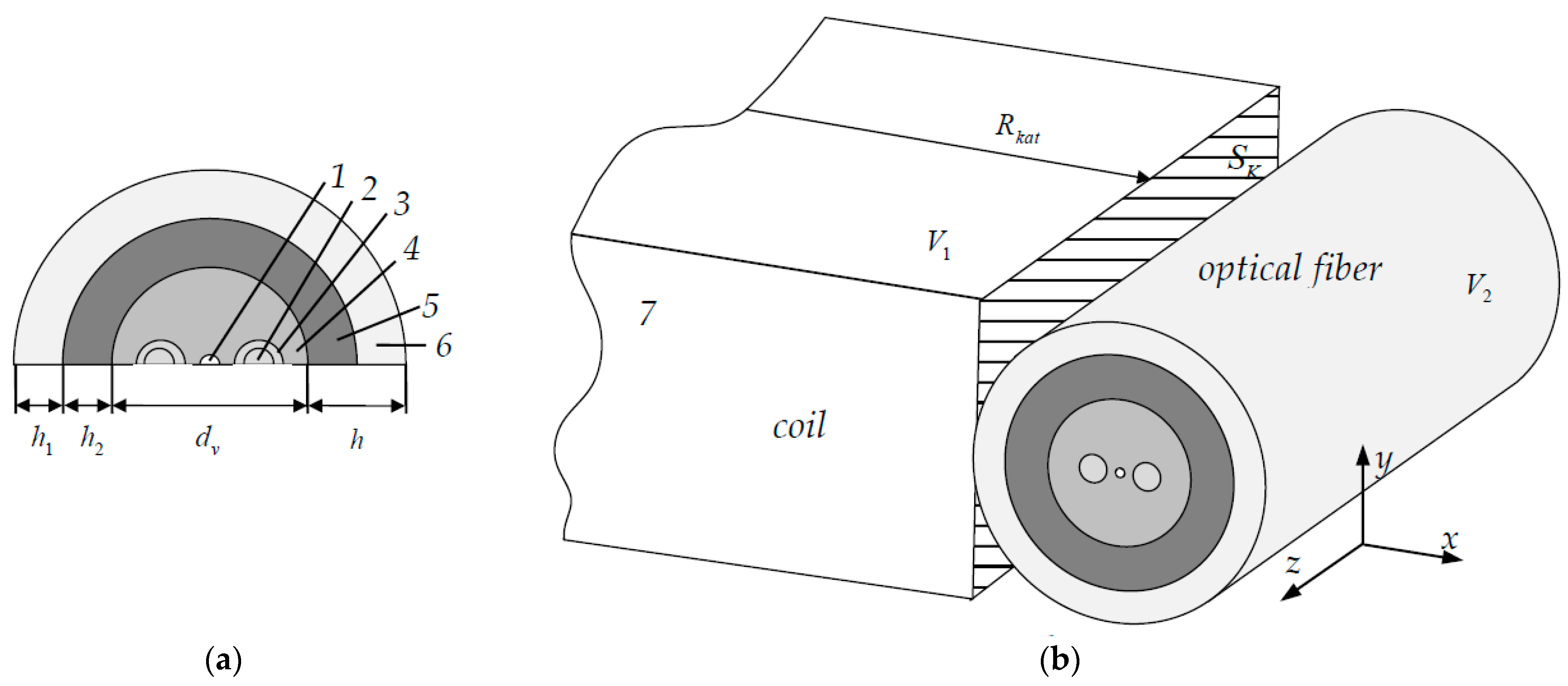
2.1. Model
2.2. Materials
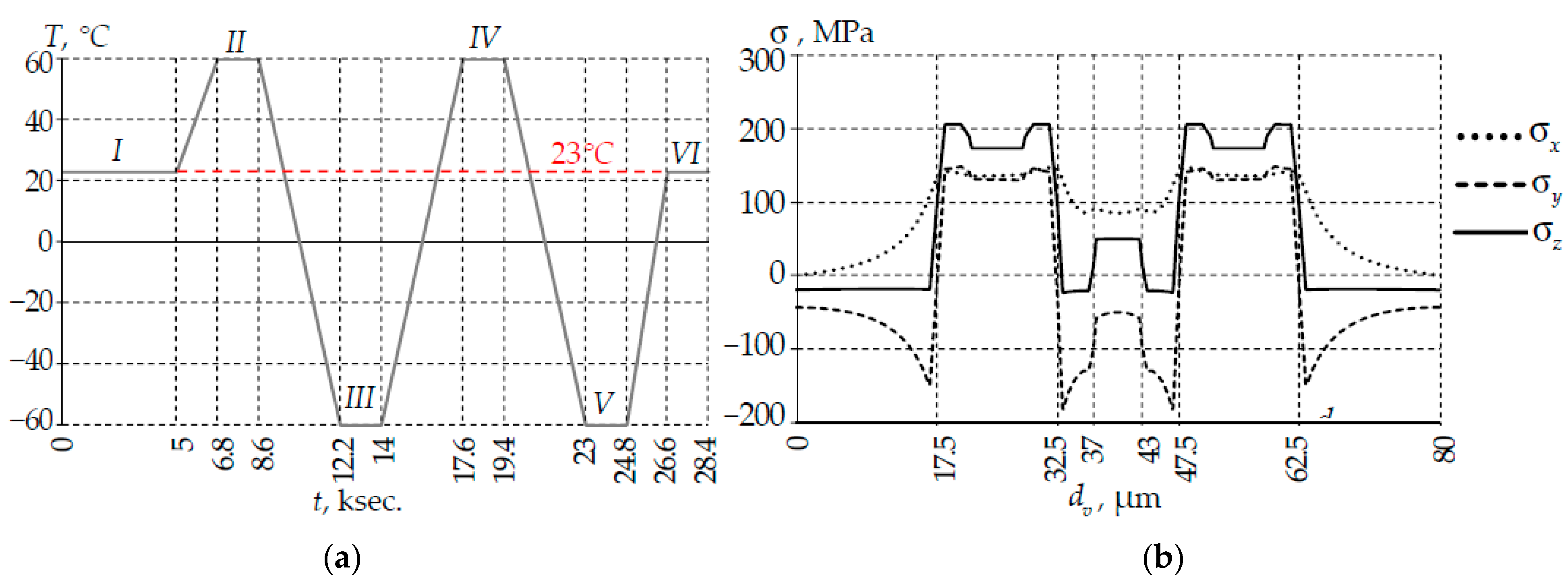
2.3. Thermal Cycle and Prestressing
2.4. Numerical Finite Element and Methods
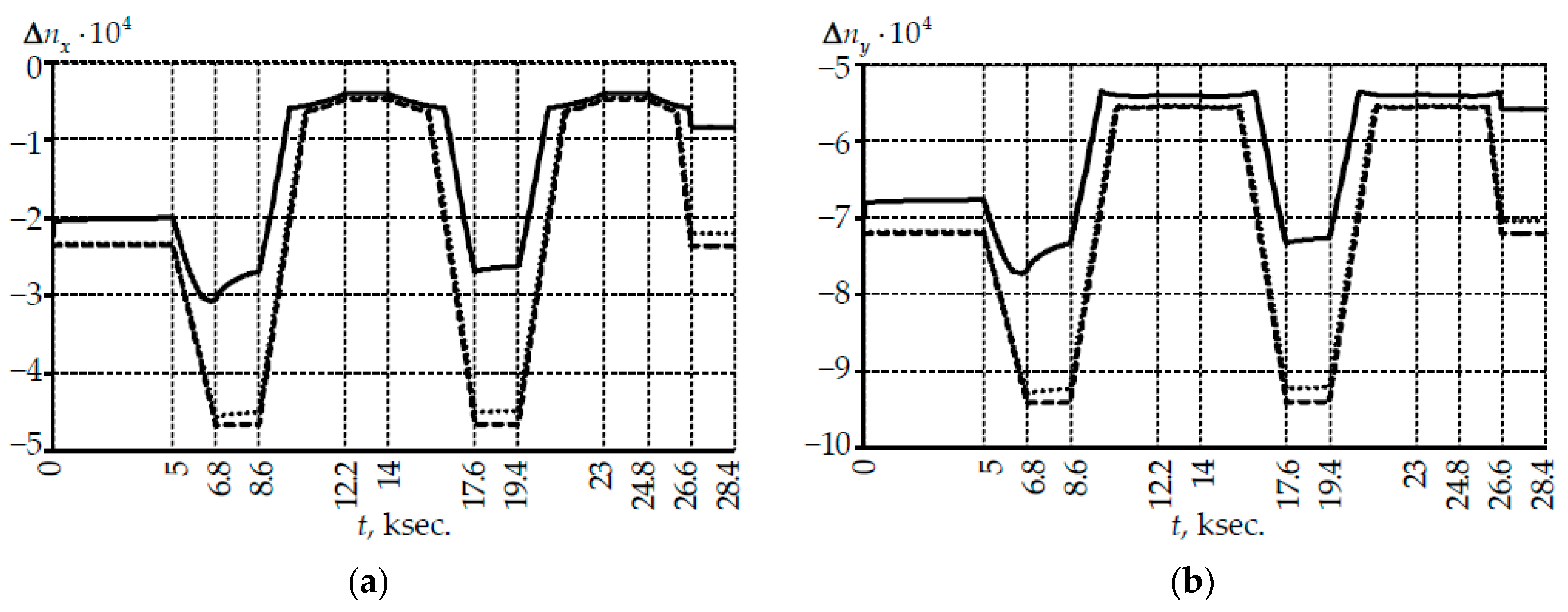
2.5. Optical Characteristics of the Fiber
3. Results
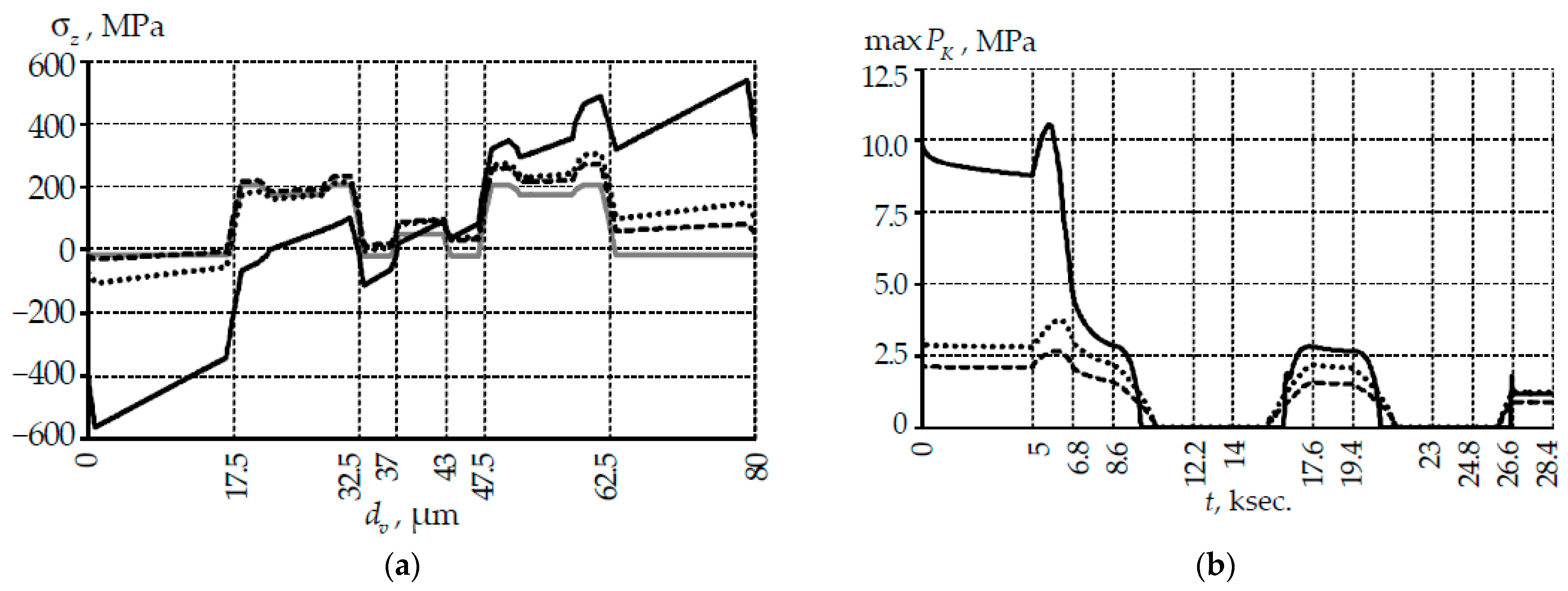
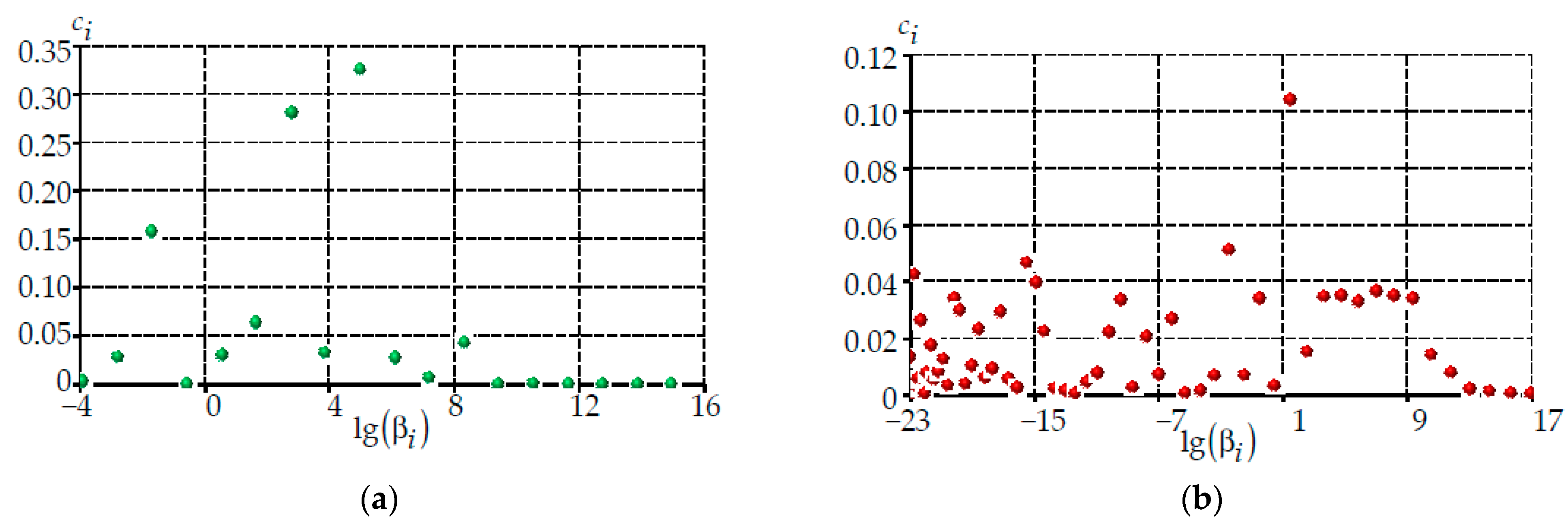
3.1. The Analysis of the Influence of the Coil Radius on the Fiber Performance under Bending and Tightness
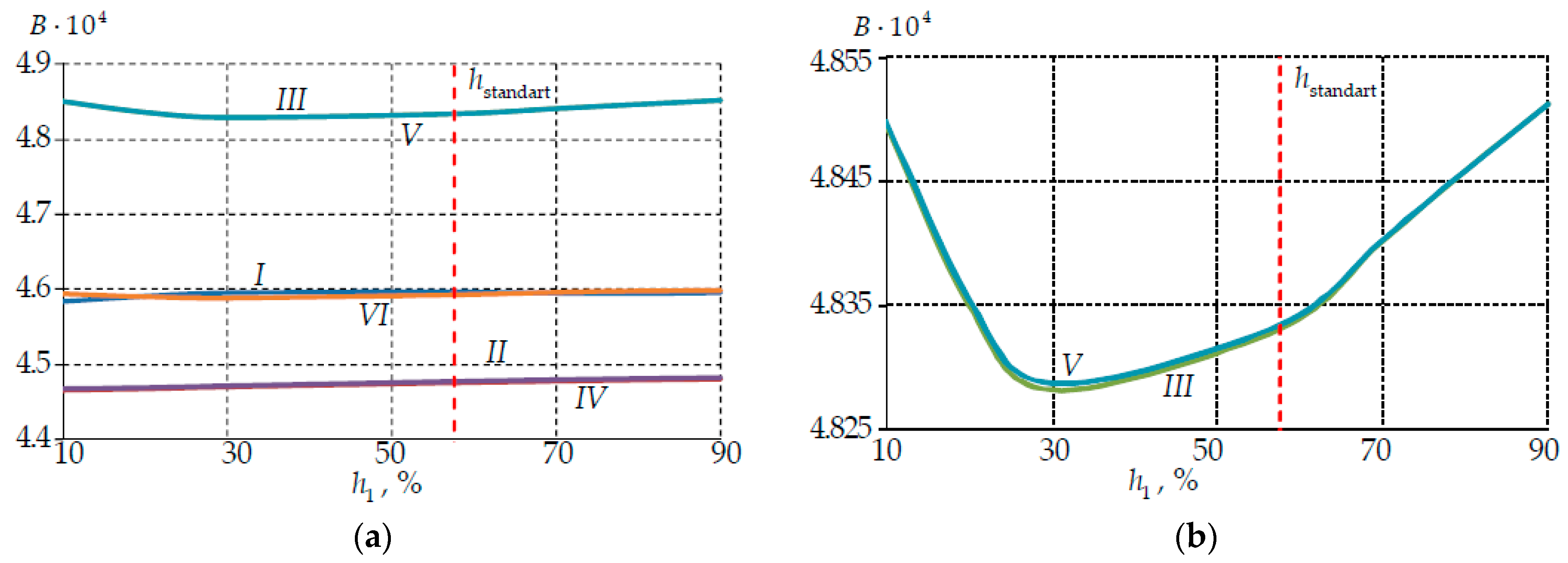
3.2. Analysis of the Influence of PC Thickness Ratio on Deformation and Optical Characteristics
4. Discussion
4.1. Limitation Statement
- Frictionless contact on the fiber-coil interface was modeled.
- The surfaces joint deformation of the protective coatings and the quartz fiber was considered.
- A constant TEC of materials was used in the model. In reference [41] the dependence of the protective coating materials TEC on temperature was established.
- The fiber has an ideal cross-sectional geometry.
- Uniform temperature change throughout the fiber and coil volume with its small change in the thermal cycle.
- Accounting for friction on the interface fiber-coil and introduction of contact between the PC layers and the quartz base is needed. The analysis of the influence of adhesion on system behavior is required.
- It is necessary to consider the dependence of PC materials TEC on temperature in the model. Materials models with variable TEC are built. Preliminary studies are completed.
- The analysis of the influence of temperature with different rates of its change both for different thermal cycles and within the same thermal cycle should be performed. Interest in this type of research is noted in [60].
- Rationalization and reduction of the PC thicknesses and its layers thicknesses ratio to minimize the fiber overall dimensions without losing the product deformation and optical characteristics is of interest.
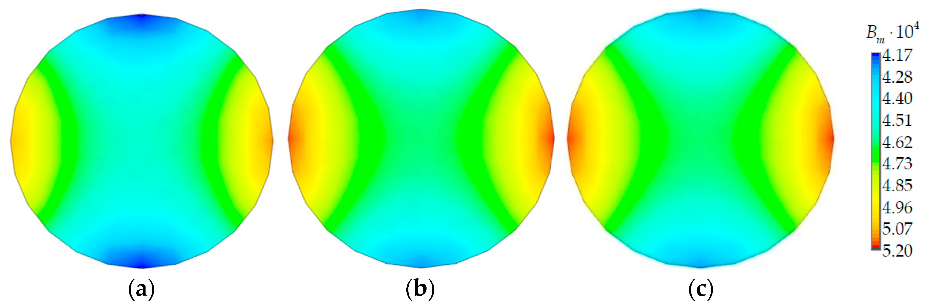
4.2. About Birefringence
4.3. Main Results
5. Conclusions
- -
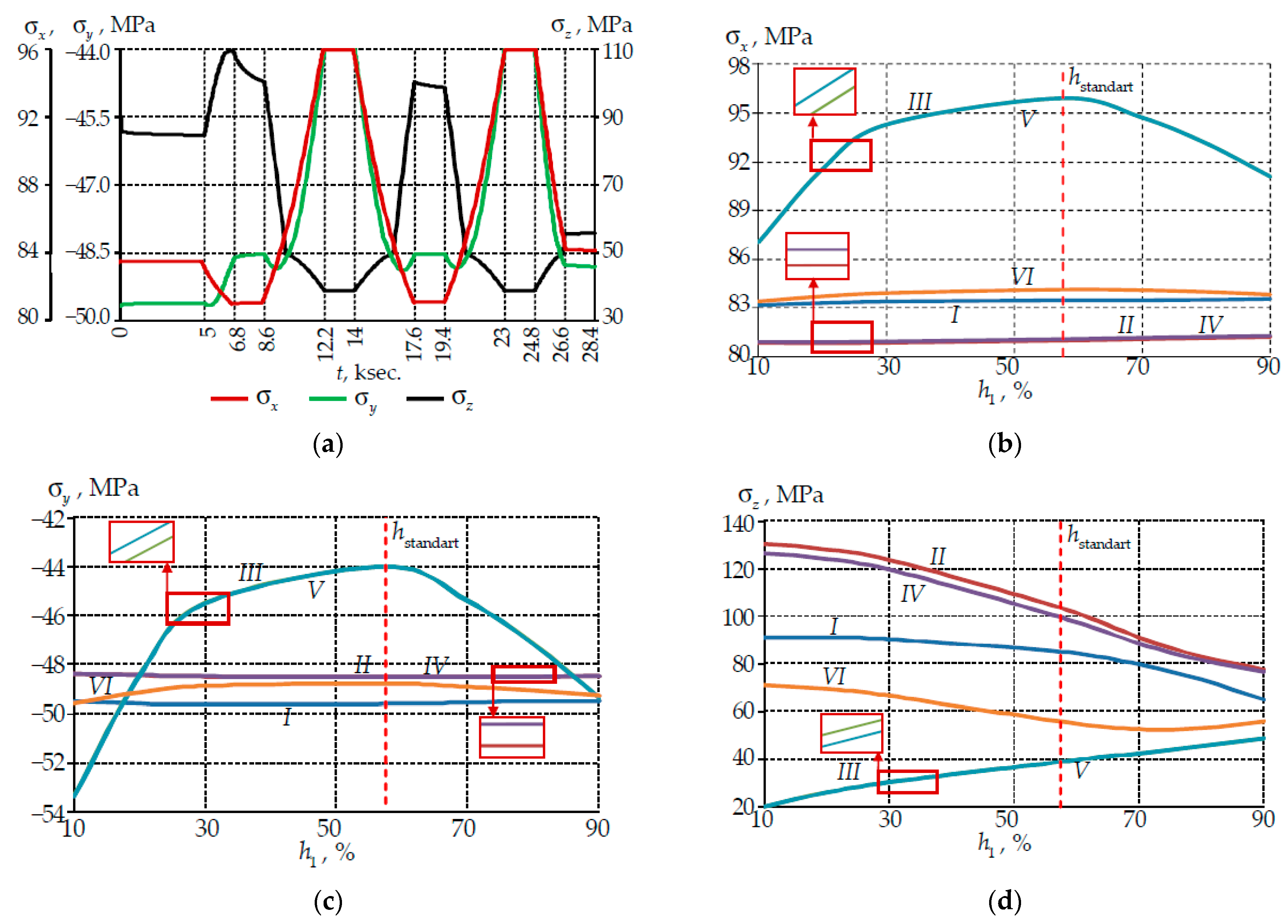
- The change in temperature during the thermal cycle affected the light-conducting core stress-strain state for all considered ratios of the polymer coating thickness. The component changed over the entire temperature range, while the and components changed at negative temperatures.
- -
- A more nonlinear pattern of the deformation behavior was observed with an increase in the percentage of the protective coating primary layer.
- -
- Permanent deformation and change in the optical characteristics of the fiber occurred when it operated under conditions of large temperature amplitudes. This may affect the quality of the signal.
- -
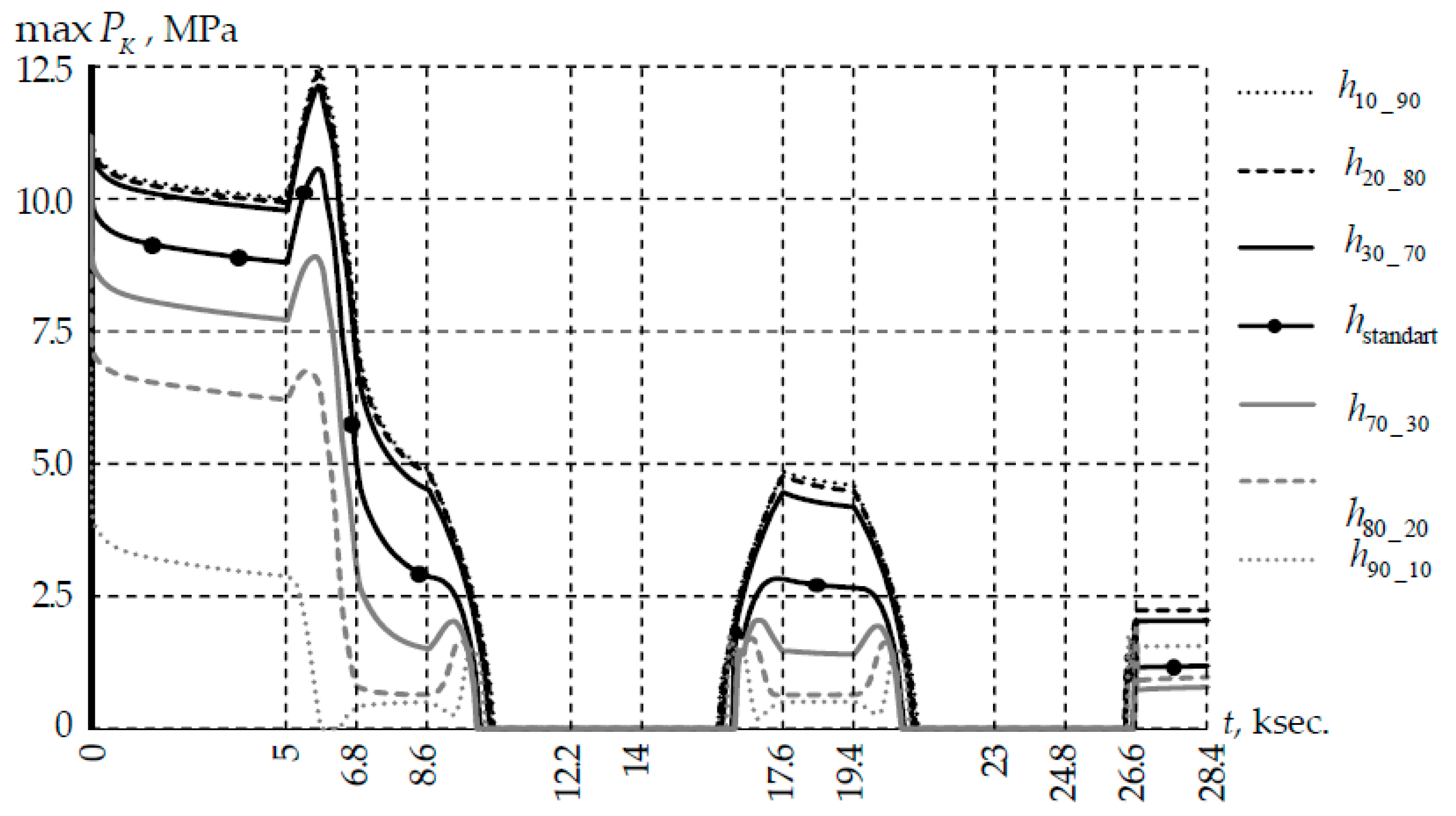
- No contact of the fiber with the coil occurred at different temperatures in the range of 2–19 °C. This was due to the material’s thermomechanical properties and the coating thicknesses percentage.
- -
- Primary coating thickness in the range of 30 to 70% of the total thickness was optimal.
- -
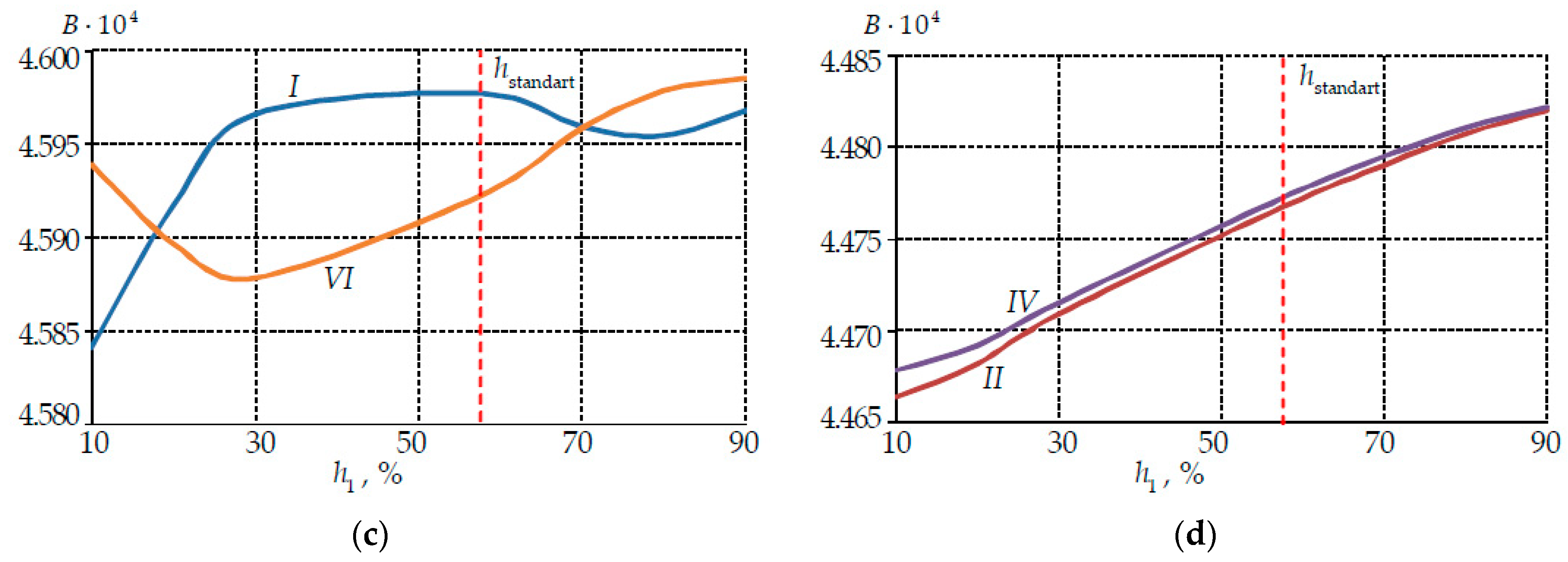
- The analysis of the existing formulas for determining the fiber optical characteristics was completed. It was established that the difference between the quantitative values of the optical characteristics calculated using different formulas did not exceed 5%.
Author Contributions
Funding
Institutional Review Board Statement
Informed Consent Statement
Data Availability Statement
Conflicts of Interest
References
- Renaudier, J.; Ghazisaeidi, A. Scaling capacity growth of fiber-optic transmission systems using 100+nm ultra-wideband semiconductor optical amplifiers. J. Lightwave Technol. 2019, 37, 1831–1838. [Google Scholar] [CrossRef]
- Yuexia, L.; Longyu, X.; Jinyue, Y.; Jinpeng, B. Design of a hybrid fiber optic daylighting and PV solar lighting system. Energy Procedia 2018, 145, 586–591. [Google Scholar] [CrossRef]
- Lawless, S.; Gorthala, R. Design and development of a fiber-optic hybrid day-lighting system. J. Sol. Energy Eng. 2018, 140, 021012. [Google Scholar] [CrossRef]
- Wang, Y.; Huang, Q.; Zhu, W.; Yang, M.; Lewis, E. Novel optical fiber SPR temperature sensor based on MMF-PCF-MMF structure and gold-PDMS film. Opt. Express 2018, 26, 1910–1917. [Google Scholar] [CrossRef]
- Chen, M.; Zhao, Y.; Lv, R.; Xia, F. Hybrid MEFPI/FBG sensor for simultaneous measurement of strain and magnetic field. Opt. Fiber Technol. 2017, 39, 32–36. [Google Scholar] [CrossRef]
- Schenato, L.; Galtarossa, A.; Pasuto, A.; Palmieri, L. Distributed optical fiber pressure sensors. Opt. Fiber Technol. 2020, 58, 102239. [Google Scholar] [CrossRef]
- Zhang, S.; Deng, S.; Wang, Z.; Sun, C.; Chen, X.; Ma, Y.; Zhao, L.; Lu, C.; Geng, T.; Yang, W.; et al. A miniature SMS-LPG bending sensor with high sensitivity based on multimode fiber embedded-LPG. Sens. Actuator A Phys. 2019, 295, 31–36. [Google Scholar] [CrossRef]
- Su, J. Portable and sensitive air pollution monitoring. Light Sci. Appl. 2018, 7, 3. [Google Scholar] [CrossRef]
- Yin, M.; Gu, B.; An, Q.-F.; Yang, C.; Guan, Y.L.; Yong, K.-T. Recent development of fiber-optic chemical sensors and biosensors: Mechanisms, materials, micro/nano-fabrications and applications. Coord. Chem. Rev. 2018, 376, 348–392. [Google Scholar] [CrossRef]
- Chopra, K.N. Optoelectronic Gyroscopes; Springer: Singapore, 2021. [Google Scholar] [CrossRef]
- Esposito, F.; Srivastava, A.; Iadicicco, A.; Campopiano, S. Multi-parameter sensor based on single long period grating in Panda fiber for the simultaneous measurement of SRI, temperature and strain. Opt. Laser Technol. 2019, 113, 198–203. [Google Scholar] [CrossRef]
- Zhang, X.; Chen, R.; Wang, A.; Xu, Y.; Jiang, Y.; Ming, H.; Zhao, W. Monitoring the failure forms of a composite laminate system by using panda polarization maintaining fiber Bragg gratings. Opt. Exp. 2019, 27, 17571–17580. [Google Scholar] [CrossRef] [PubMed]
- He, X.; Ma, C.; Wang, X.; Wang, Z.; Jiang, F.; Yuan, L. Metallic structure functional sensor based on embedded Panda fiber by ultrasonic additive manufacturing. Appl. Opt. 2020, 59, 4880–4887. [Google Scholar] [CrossRef] [PubMed]
- Lezzi, P.J.; Evke, E.E.; Aaldenberg, E.M.; Tomozawa, M. Surface Crystallization and Water Diffusion of Silica Glass Fibers: Causes of Mechanical Strength Degradation. J. Am. Ceram. Soc. 2015, 98, 2411–2421. [Google Scholar] [CrossRef]
- El Abdi, R.; Leite Pinto, R.; Guérard, G.; Capena, C. Influence of environment atmosphere on optical fiber strength. Int. J. Mechatron. Appl. Mech. 2022, 11, 41–43. [Google Scholar]
- Mendez, A.; Morse, T.F. Specialty Optical Fibers Handbook; Elsevier Inc.: Butlington, VT, USA, 2007. [Google Scholar] [CrossRef]
- Petrie, C.; Sridharan, N.; Subramanian, M.; Hehr, A.; Norfolk, M.; Sheridan, J. Embedded metallized optical fibers for high temperature applications. Smart Mater. Struct. 2019, 28, 055012. [Google Scholar] [CrossRef]
- Romashova, V.B.; Shaimadiyeva, D.S.; Burov, N.V. Research of optical fiber’s hermetic carbon coatings used in harsh conditions. Photonics 2019, 13, 476–484. [Google Scholar] [CrossRef]
- Zhang, Y.; Qu, L.; Liu, J.; Wu, X.; Zhang, Y.; Zhang, R.; Qi, H.; Zhang, X. Synthesis and characterization of high-temperature-resistant and optically transparent polyimide coatings for potential applications in quartz optical fibers protection. J. Coat. Technol. Res. 2019, 16, 511–520. [Google Scholar] [CrossRef]
- Bulatov, M.I.; Shatsov, A.A. Strength and Fracture Resistance of Quartz Fibers with Polyimide Coatings. Russ. J. Non-Ferr. Met. 2021, 62, 756–762. [Google Scholar] [CrossRef]
- Han, Y.; Yan, X.; Tao, Y. Effect of Transparent, Purple, and Yellow Shellac Microcapsules on the Optical Properties and Self-Healing Performance of Waterborne Coatings. Coatings 2022, 12, 1056. [Google Scholar] [CrossRef]
- Wang, Q.J.; Chung, Y.W. Antifriction Materials and Composites; Springer: Boston, MA, USA, 2013. [Google Scholar] [CrossRef]
- Lin, Z.; Zhang, K.; Ye, J.; Li, X.; Zhao, X.; Qu, T.; Liu, Q.; Gao, B. The effects of filler type on the friction and wear performance of PEEK and PTFE composites under hybrid wear conditions. Wear 2022, 490–491, 204178. [Google Scholar] [CrossRef]
- Abdul Samad, M. Recent Advances in UHMWPE/UHMWPE Nanocomposite/UHMWPE Hybrid Nanocomposite Polymer Coatings for Tribological Applications: A Comprehensive Review. Polymers 2021, 13, 608. [Google Scholar] [CrossRef] [PubMed]
- Adamov, A.A.; Kamenskih, A.A.; Pankova, A.P. Numerical analysis of the spherical bearing geometric configuration with antifriction layer made of different materials. PNRPU Mech. Bull. 2020, 4, 15–26. [Google Scholar] [CrossRef]
- Thakur, T.; Gaur, B.; Singha, A.S. Bio-based epoxy/imidoamine encapsulated microcapsules and their application for high performance self-healing coatings. Prog. Org. Coat. 2021, 159, 106436. [Google Scholar] [CrossRef]
- Han, Y.; Yan, X.; Tao, Y. Effect of Transparent, Purple, and Yellow Shellac Microcapsules on Properties of the Coating on Paraberlinia bifoliolata Surface. Polymers 2022, 14, 3304. [Google Scholar] [CrossRef]
- Huang, N.; Yan, X.; Han, Y. Preparation of Melamine-Formaldehyde Resin/Rice Husk Powder Coated Epoxy Resin Microcapsules and Effects of Different Microcapsule Contents on the Properties of Waterborne Coatings on Tilia europaea Surface. Coatings 2022, 12, 1213. [Google Scholar] [CrossRef]
- Azanova, I.S.; Shevtsov, D.I.; Vokhmyanina, O.L.; Saranova, I.D.; Smirnova, A.N.; Bulatov, M.I.; Pospelova, E.A.; Sharonova, Y.O.; Dimakova, T.V.; Kashaykin, P.F.; et al. Experience of the Development of Heat-resistant, Radiation-resistant and Hydro-resistant Optical Fibre. Photonics 2019, 13, 444–450. [Google Scholar] [CrossRef]
- Li, H.; Li, X.; Wang, J.; Rochette, M.; Yang, H. High extinction ratio elliptical core Panda-type polarization-maintaining fiber coil. Opt. Lett. 2021, 46, 4276–4279. [Google Scholar] [CrossRef]
- Kilinc, E.; Bell, A.M.T.; Bingham, P.A.; Hand, R.J. Effects of composition and phase relations on mechanical properties and crystallization of silicate glasses. J. Am. Ceram. Soc. 2021, 104, 3921–3946. [Google Scholar] [CrossRef]
- Ballato, J.; Ebendorff-Heidepriem, H.; Zhao, J.; Petit, L.; Troles, J. Glass and Process Development for the Next Generation of Optical Fibers: A Review. Fibers 2017, 5, 11. [Google Scholar] [CrossRef]
- Lesiak, P.; Wolinski, T. Numerical analysis of stress distribution in embedded highly birefringent PANDA fibers. In Proceedings of the 24th International Conference on Optical Fibre Sensors, Curitiba, Brazil, 28 September 2015–2 October 2015. [Google Scholar] [CrossRef]
- Liu, J.; Liu, Y.; Xu, T. Analytical Estimation of Stress-Induced Birefringence in Panda-Type Polarization-Maintaining Fibers. IEEE Photonics Technol. Lett. 2020, 32, 1507–1510. [Google Scholar] [CrossRef]
- Esipenko, I.A.; Lykov, D.A.; Smetannikov, O.Y. Using the transversely isotropic characteristics of the coil to calculate the thermal-drift parameters of a fiber-optic gyroscope. J. Opt. Technol. 2019, 86, 289–295. [Google Scholar] [CrossRef]
- Popelka, M.; Stolov, A.; Hokansson, A.; Li, J.; Hines, M. A new polyimide coating for optical fibers: Demonstration of advantageous characteristics in harsh environments. In Proceedings of the Spie—The International Society for Optical Engineering, San Francisco, CA, USA, 22 January–28 February 2022; p. 119970J. [Google Scholar] [CrossRef]
- Goicoechea, J.; Hernaez, M.; Zamarreño, C.; Arregui, F. Coatings for Optical Fiber Sensors. Compr. Mater. Processing 2014, 13, 103–119. [Google Scholar]
- Babkin, O.E.; Babkina, L.A.; Aikasheva, O.S.; Il’ina, V.V. Photopolymeric Coatings for Fiber-Optic Cables. Fibre Chem. 2019, 50, 499–503. [Google Scholar] [CrossRef]
- Rivero, P.J.; Goicoechea, J.; Arregui, F.J. Optical Fiber Sensors Based on Polymeric Sensitive Coatings. Polymers 2018, 10, 280. [Google Scholar] [CrossRef] [PubMed]
- Dorobantu, D.; Jderu, A.; Enachescu, M.; Ziegler, D. Fabrication of Optical Fibers with Multiple Coatings for Swelling-Based Chemical Sensing. Micromachines 2021, 12, 941. [Google Scholar] [CrossRef]
- Shardakov, I.N.; Trufanov, A.N. Identification of the Temperature Dependence of the Thermal Expansion Coefficient of Polymers. Polymers 2021, 13, 3035. [Google Scholar] [CrossRef]
- Chen, Y.-F. Power Losses in Deformed Polymer Optical Fiber Under High Temperature. J. Lightwave Technol. 2007, 24, 4983–4990. [Google Scholar] [CrossRef]
- Bulatov, M.I.; Shatsov, A.A. Destruction of silica fibers with different protective coatings. Bull. PNRPU. Mech. Eng. Mater. Sci. 2021, 23, 47–52. [Google Scholar] [CrossRef]
- Grandes, J.; Illarramendi, M.; Arrospide, E.; Bikandi, I.; Aramburu, I.; Guarrotxena, N.; García, O.; Zubia, J. Temperature effects on the emission of polymer optical fibers doped with Lumogen dyes. Opt. Fiber Technol. 2022, 72, 102980. [Google Scholar] [CrossRef]
- Lesnikova, Y.I.; Trufanov, A.N. The effect of contact influence on the opticomechanical properties of Panda-type fiber under thermocycling conditions. J. Phys. Conf. Ser. 2018, 1129, 012023. [Google Scholar] [CrossRef]
- Trufanov, A.N.; Trufanov, N.A.; Semenov, N.V. Numerical analysis of residual stresses in preforms of stress applying part for PANDA-type polarization maintaining optical fibers in view of technological imperfections of the doped zone geometry. Opt. Fiber Technol. 2016, 31, 83–91. [Google Scholar] [CrossRef]
- Leitão, C.; Pereira, S.O.; Marques, C.; Cennamo, N.; Zeni, L.; Shaimerdenova, M.; Ayupova, T.; Tosi, D. Cost-Effective Fiber Optic Solutions for Biosensing. Biosensors 2022, 12, 575. [Google Scholar] [CrossRef] [PubMed]
- Bosch, M.E.; Sánchez, A.J.R.; Rojas, F.S.; Ojeda, C.B. Recent Development in Optical Fiber Biosensors. Sensors 2007, 7, 797–859. [Google Scholar] [CrossRef]
- Quartz Glass for Optics. Data and Properties; Heraeus Quarzglas GmbH & Co. KG: Hanau, Germany, 2019; Available online: https://www.heraeus.com/media/media/hca/doc_hca/products_and_solutions_8/optics/Data_and_Properties_Optics_fused_silica_EN.pdf (accessed on 10 August 2022).
- DSM Desotech Inc. Product Data. DeSolite 3471-1-152A.; DSM Desotech Inc.: Elgin, IL, USA, 2015; Available online: https://drive.google.com/file/d/1MODJPy0jBUxYzSzJmQPEaVqoyI-70dBc/view?usp=sharing (accessed on 10 August 2022).
- DSM Desotech Inc. Product Data. DeSolite DS-2015; DSM Desotech Inc.: Elgin, IL, USA, 2015; Available online: https://focenter.com/wp-content/uploads/documents/AngstromBond---Fiber-Optic-Center-AngstromBond-DSM-DS-2015-UV-Cure-Secondary-Coating-(1Kg)-Fiber-Optic-Center.pdf (accessed on 31 July 2022).
- Bergström, J. Mechanics of Solid Polymers; Elsevier Inc.: New York, NY, USA, 2015. [Google Scholar] [CrossRef]
- Williams, M.L.; Landel, R.F.; Ferry, J.D. The temperature dependence of relaxation mechanisms in amorphous polymers and other glass-forming liquids. J. Am. Chem. Soc. 1955, 14, 3701–3707. [Google Scholar] [CrossRef]
- Guan, R.; Zhu, F.; Gan, Z.; Huang, D.; Liu, S. Stress birefringence analysis of polarization maintaining optical fibers. Opt. Fiber Technol. 2005, 11, 240–254. [Google Scholar] [CrossRef]
- Li, H.; Li, X.; Zhang, Y.; Liu, P.; Yang, H. Design of high birefringence stress-induced polarization-maintaining fiber based on utilizing geometrical birefringence. Opt. Fiber Technol. 2019, 53, 102065. [Google Scholar] [CrossRef]
- Li, M.; Li, X.; Li, H. Design of ultrahigh birefringent stress-induced polarization-maintaining fiber with hole-assistance. Opt. Fiber Technol. 2021, 67, 102707. [Google Scholar] [CrossRef]
- Park, Y.; Paek, U.C.; Kim, D.Y. Characterization of a stress-applied polarization-maintaining (PM) fiberthrough photoelastic tomography. J. Lightwave Technol. 2003, 21, 997–1004. [Google Scholar] [CrossRef]
- Kashaykin, P.F.; Pospelova, E.A.; Sharonova, Y.O.; Vokhmyanina, O.L.; Azanova, I.S.; Tomashuk, A.L. Temperature and polarization dependence of radiation-induced attenuation in pure-silica-core PANDA optical fiber. Opt. Mater. 2022, 131, 112510. [Google Scholar] [CrossRef]
- Ramadan, W.A.; Wahba, H.H.; Shams El-Din, M.A. Two-dimensional refractive index and birefringence profiles of a graded index bent optical fibre. Opt. Fiber Technol. 2017, 36, 115–124. [Google Scholar] [CrossRef]
- Yang, H.; Qiao, L.; Yang, Y.; Huang, W.; Sun, S. Thermally induced error analysis and suppression of optic fiber delay loop in the different variable rate of temperature. Optik 2019, 193, 162994. [Google Scholar] [CrossRef]
- Varnham, M.; Payne, D.; Barlow, A.; Birch, R. Analytic solution for the birefringence produced by thermal stress in polarization-maintaining optical fibers. J. Lightwave Technol. 1983, 1, 332–339. [Google Scholar] [CrossRef]
- Yablon, A.D. Optical and mechanical effects of frozen-in stresses and strains in optical fibers. IEEE J. Sel. Top. Quantum Electron. 2004, 10, 300–311. [Google Scholar] [CrossRef]
- Wang, H.; Tu, F.; Li, J.; Wei, H.; Wang, S. Effect of Temperature and Bending on PANDA Polarization-maintaining Fibers Fabricated by PCVD Method. In Proceedings of the 2008 IEEE PhotonicsGlobal@Singapore, Singapore, 8–11 December 2008; pp. 1–4. [Google Scholar] [CrossRef]
- Ghanbarzadeh-Dagheyan, A.; Jalili, N.; Ahmadian, M.T. A holistic survey on mechatronic Systems in Micro/Nano scale with challenges and applications. J. Micro-Bio Robot. 2021, 17, 1–22. [Google Scholar] [CrossRef]
- Ji, Y.; Yang, W.; Wang, Y.; Li, Z. Overview of Foreign Inertial Technology Development. Lect. Notes Electr. Eng. 2022, 861, 975–983. [Google Scholar] [CrossRef]
- Jin, J.; He, J.; Ma, K.; Kong, L. Digital Closed-loop Fiber Optic Gyroscopes—A Choice for Micro/Nano-Satellites Applicatio. In Proceedings of the 2019 IEEE International Symposium on Inertial Sensors and Systems (INERTIAL), Naples, FL, USA, 1–5 April 2019; pp. 1–4. [Google Scholar] [CrossRef]
- Singh, B.; Rana, H.; Kumar, S.; Bhulania, P.; Minocha, G. A novel design of fiber optic gyroscope based INS system for U AS applications. Procedia Comput. Sci. 2015, 57, 1317–1323. [Google Scholar] [CrossRef]
- Larkin, K.; Ghommem, M.; Serrano, M.; Abdelkefi, A. A review on vibrating beam-based micro/nano-gyroscopes. Microsyst. Technol. 2021, 27, 4157–4181. [Google Scholar] [CrossRef]


| Parameter | Designation of the Thicknesses Ratio of the PC | ||||||
|---|---|---|---|---|---|---|---|
| h10_90 | h20_80 | h30_70 | hstandard | h70_30 | h80_20 | h90_10 | |
| h1 (μm) | 4.35 | 8.7 | 13.05 | 25 | 30.45 | 34.8 | 39.15 |
| h2 (μm) | 39.15 | 34.8 | 30.45 | 18.5 | 13.05 | 8.7 | 4.35 |
| h1 (%) of h | 10 | 20 | 30 | 57.5 | 70 | 80 | 90 |
| h1 (%) of h | 90 | 80 | 70 | 42.5 | 30 | 20 | 10 |
| Parameter | Mat. 1 | Mat. 2 | Mat. 3 | Mat. 4 | Mat. 5 | Mat. 6 | Mat. 7 |
|---|---|---|---|---|---|---|---|
| E (MPa) | 67939 | 49107 | 65370 | 72000 | 1837 | 7786 | 68600 |
| v | 0.168 | 0.203 | 0.181 | 0.170 | 0.498 | 0.350 | 0.340 |
| α·10−6 (K−1) | 1.055 | 2.675 | 2.886 | 0.500 | 200 | 50 | 23 |
| Parameter | Analytic | Calculation | ||
|---|---|---|---|---|
| Rcoil (mm) | ||||
| 5 | 22 | 50 | ||
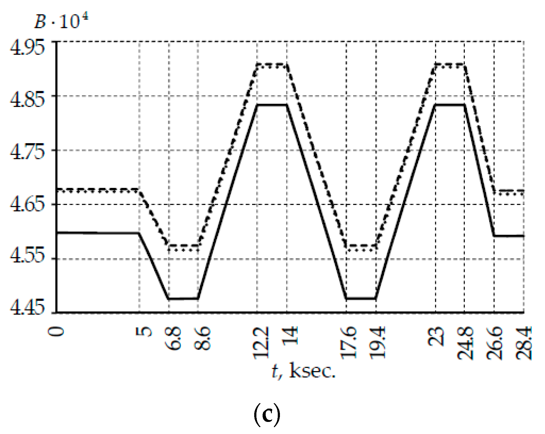
| B | 4.83 × 10⁻⁴ | 4.592 × 10⁻⁴ | 4.669 × 10⁻⁴ | 4.676 × 10⁻⁴ |
| Δ (%) | – | 4.83 | 3.24 | 3.09 |
Publisher’s Note: MDPI stays neutral with regard to jurisdictional claims in published maps and institutional affiliations. |
© 2022 by the authors. Licensee MDPI, Basel, Switzerland. This article is an open access article distributed under the terms and conditions of the Creative Commons Attribution (CC BY) license (https://creativecommons.org/licenses/by/4.0/).
Share and Cite
Lesnikova, Y.I.; Trufanov, A.N.; Kamenskikh, A.A. Analysis of the Polymer Two-Layer Protective Coating Impact on Panda-Type Optical Fiber under Bending. Polymers 2022, 14, 3840. https://doi.org/10.3390/polym14183840
Lesnikova YI, Trufanov AN, Kamenskikh AA. Analysis of the Polymer Two-Layer Protective Coating Impact on Panda-Type Optical Fiber under Bending. Polymers. 2022; 14(18):3840. https://doi.org/10.3390/polym14183840
Chicago/Turabian StyleLesnikova, Yulia I., Aleksandr N. Trufanov, and Anna A. Kamenskikh. 2022. "Analysis of the Polymer Two-Layer Protective Coating Impact on Panda-Type Optical Fiber under Bending" Polymers 14, no. 18: 3840. https://doi.org/10.3390/polym14183840
APA StyleLesnikova, Y. I., Trufanov, A. N., & Kamenskikh, A. A. (2022). Analysis of the Polymer Two-Layer Protective Coating Impact on Panda-Type Optical Fiber under Bending. Polymers, 14(18), 3840. https://doi.org/10.3390/polym14183840