Article

Co/ZnO/Nitrogen-Doped Carbon Composite Anode Derived from Metal Organic Frameworks for Lithium Ion Batteries

1
Department of Chemical Engineering, R&D Center for Membrane Technology, Research Center for Semiconductor Materials and Advanced Optics, Chung Yuan Christian University, Taoyuan City 320, Taiwan
2
Department of Electrical Engineering, National University of Tainan, Tainan City 700, Taiwan
3
Metal Industries Research and Development Centre, Kaohsiung 701, Taiwan
*
Author to whom correspondence should be addressed.
Polymers 2022, 14(15), 3085; https://doi.org/10.3390/polym14153085
Submission received: 7 June 2022 / Revised: 20 July 2022 / Accepted: 27 July 2022 / Published: 29 July 2022
(This article belongs to the Special Issue Polymer Materials for Energy Storage and Fuel Cells Applications)

Abstract

:
Through high-temperature sintering and carbonization, two Co/ZnO nitrogen-doped porous carbon (NC) composites derived from ZIF-8 and ZIF-67 were manufactured for use as anodes for Li ion batteries: composite-type Co/ZnO-NC and core-shell-type Co@ZnO-NC. X-ray diffraction analysis, scanning electron microscopy, and the Brunauer–Emmett–Teller (BET) method were performed to identify the pore distribution and surface morphology of these composites. The findings of the BET method indicated that the specific surface area of Co/ZnO-NC was 350 m2/g, which was twice that of Co@ZnO-NC. Electrochemical measurements revealed that Co@ZnO-NC and Co/ZnO-NC had specific capacities of over 400 mAh g−1 at a current density 0.2 A g−1 after 50 cycles. After 100 cycles, Co/ZnO-NC exhibited a reversible capacity of 411 mAh g−1 at a current density of 0.2 A g−1 and Co@ZnO-NC had a reversible capacity of 246 mAh g−1 at a current density of 0.2 A g−1. The results indicated that Co/ZnO-NC exhibited superior electrochemical performance to Co@ZnO-NC as a potential anode for use in Li ion batteries.

Graphical Abstract

1. Introduction

With developments in technology, the number of products such as smartphones, digital cameras, and laptops is increasing. Thus, energy storage devices with a small size, a light weight, and a high performance are required [1]. Among rechargeable batteries, lithium ion batteries (LIBs) have attracted considerable attention due to their low raw material cost, high capacity, high battery voltage, long cycle life, and excellent stability at high temperatures [2,3]. LIBs are internationally recognized as the most favourable chemical energy source available. Most LIBs used in commercial applications employ carbon materials, such as graphite, as anode materials. However, the theoretical capacity of graphite anode materials is only 372 mAh/g, which is not adequate for use in LIBs [4,5,6]. Thus, it is urgent to develop higher reversible capacity anode materials for Li ion batteries.
Recently, metal organic frameworks (MOFs) have become increasingly popular because of their advantages of easy preparation, high porosity, high specific surface area, and adjustable pore size [7,8]. Metal–organic frameworks (MOFs) are fabricated by linking inorganic and organic units by weak bonds (reticular synthesis), which form porous materials with a periodic network structure through self-assembly under the actions of coordination bonds [9,10,11,12]. Due to the simplicity and low cost of preparing MOFs, they have considerable potential for future applications, including gas storage [10,11,12,13,14,15,16], drug delivery [17,18,19,20,21], molecular separation [22,23,24,25], chemical catalysis [26,27,28,29,30,31], and energy storage [32,33,34,35,36,37,38,39,40,41,42,43,44]. According to Tai et al.’s work, the as-synthesized ZIF-8 calcined at 800 °C under an N2 atmosphere and converted to N-doped carbon can be used as an anode for LIBs. The reversible discharge capacity of 440.5 mA g−1 at 1 A g−1 is over 100 cycles [35]. Son et al. synthesized ZIF-8 under N2 flow and impregnated in thiourea and ethanol solution; the material was then calcined under N2 at 900 °C. Finally, they synthesized N, S-doped nanocarbon, which exhibited high electrochemical performance [36]. Tang et al. proposed ZIF-8@ZIF-67 core-shell nanostructures by using a seed-mediated growth technique [37]. Cheng et al. calcined ZIF-8@ZIF-67 in a tube furnace at 600 °C under the N2 atmosphere and then subjected it to oxidation in a muffle furnace at 350 °C to obtain ZnO/Co3O4/N-doped carbon nanocages as anode materials for LIBs. The composite exhibited a reversible capacity of 1305 mAh g−1 at 0.1 A g−1 after 300 cycles [38]. Huang et al. subjected porous Co-Zn/N-C polyhedral nanocages to carbonization under the Ar atmosphere at 800 °C and used the resulting materials as anodes for LIBs; the materials exhibited a reversible capacity of 702 mAh g−1 at 0.1 A g−1 after 400 cycles and exhibited satisfactory cycling stability [39]. Zhao et al. demonstrated a ZnO/Co3O4/CoO/Co composite derived from ZIF-8 and ZIF-67 as precursors and subsequently calcined under the N2 flow at 600 °C and then at 200 °C in air atmosphere. The ZnO/Co3O4/CoO/Co composite anode exhibit a high reversible capacity and excellent cycling performance for Li ion batteries [40].
In this study, we propose two different kinds of Co/ZnO/nitrogen-doped carbon composite anode via two synthesis methods to investigate the structure and electrochemical behaviour of anode materials for Li ion batteries. In the first method, ZIF-8 and ZIF-67 precursors were mixed and stirred to produce ZIF-8/ZIF-67. In the second method, ZIF-8 powder was added to ZIF-67 precursors and stirred to produce ZIF-8@ZIF-67. After high-temperature treatment and carbonization, two samples (Co/ZnO-NC and Co@ZnO-NC) were synthesized as anode materials for LIBs. Tests were then conducted on the samples, including X-ray diffraction (XRD), scanning electron microscopy (SEM), Brunauer–Emmett–Teller (BET) analysis, charge/discharge tests, cyclic voltammetry (CV), and A.C. impedance. The results indicated that the as-synthesized Co/ZnO-NC composite anodes have potential use as anode materials for LIBs.

2. Materials and Methods

2.1. Synthesis of ZIF-8

In total, 1.89 g of Zn(NO3)2·6H2O (98%, Alfa Aesar, MA, USA) was added to 50 mL of methanol (99%, TEDIA, Fairfield, CT, USA), and 3.92 g of 2-methylimidazole (99%, ACROS, NJ, USA) was then dissolved in 25 mL of methanol. The two solutions were mixed, followed by magnetic stirring for 24 h at room temperature to obtain a mixing solution. The resultant precipitate was collected through centrifugation and washed with methanol three times. Finally, the precipitate was dried at 80 °C for 24 h.

2.2. Synthesis of the ZIF-8@ZIF-67 Composite

In total, 0.42 g of ZIF-8 was added to 25 mL of methanol (solution A). Simultaneously, 1.98 g of Co(NO3)2·6H2O (98%, SHOWA, Tokyo City, Japan) was added to 50 mL of methanol (solution B), and 3.98 g of 2-methyl imidazole was dissolved in 25 mL of methanol (solution C). Subsequently, solutions B and C were simultaneously poured into solution A. The mixed solution was stirred for 24 h at room temperature and then collected through centrifugation and washed thrice with methanol. The solution was then dried in an oven at 80 °C for 24 h, and a purple powder was obtained.

2.3. Synthesis of the ZIF-8/ZIF-67 Composite

In total, 7.9 g of 2-methyl imidazole was dissolved in 100 mL of methanol. Subsequently, 1.89 g of Zn(NO3)2·6H2O and 1.98 g of Co(NO3)2·6H2O were simultaneously added to the solution. The mixed solution was stirred for 24 h at room temperature to obtain a mixing solution. The resultant precipitate was collected through centrifugation and washed thrice with methanol. Finally, the precipitate was dried at 80 °C for 24 h to obtain the requisite sample.

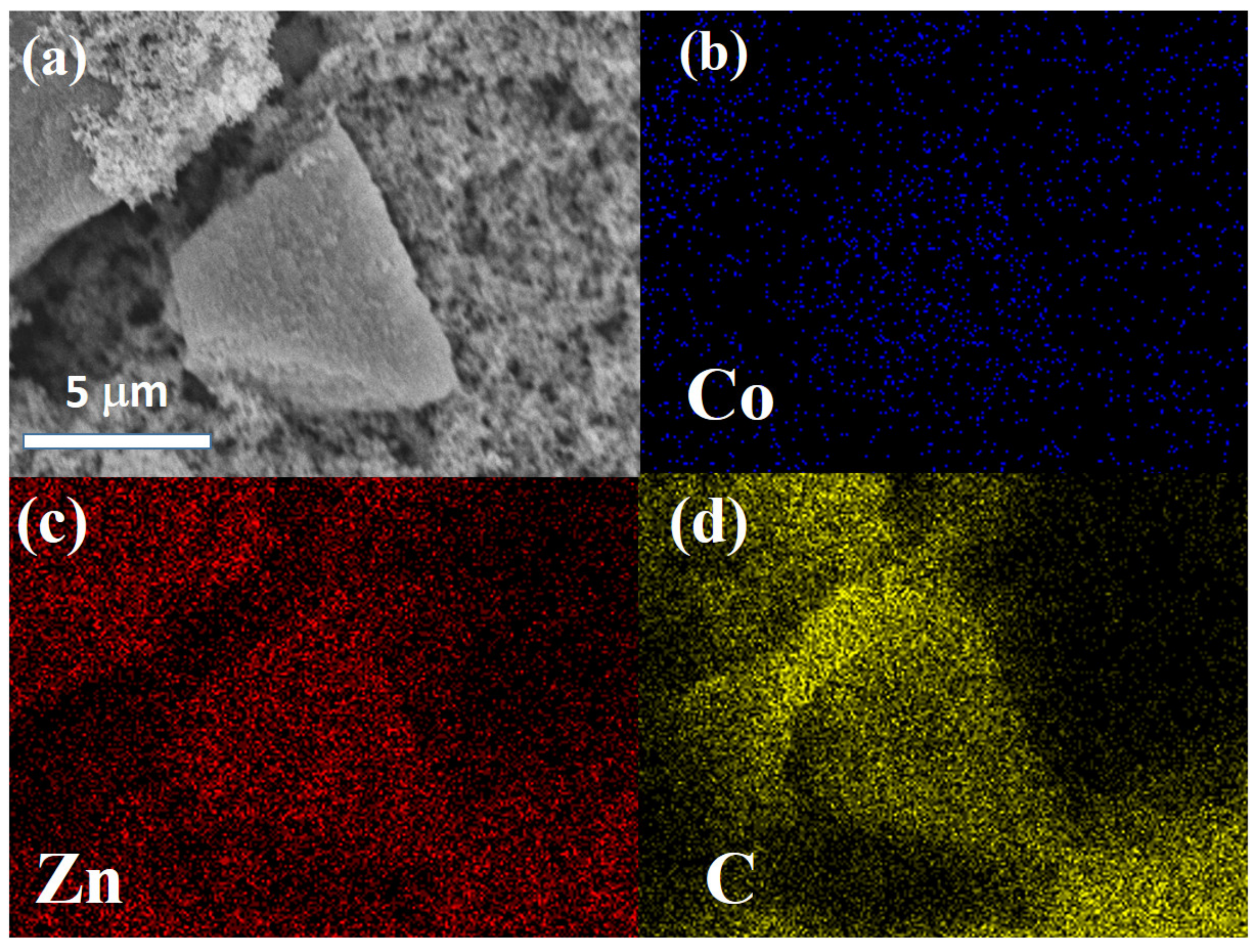
2.4. Synthesis of Co/ZnO-NC and Co@ZnO-NC Composites

ZIF-8/ZIF-67 and ZIF-8@ZIF-67 samples were calcined at 800 °C under the Ar atmosphere at a heating rate of 5 °C min−1. Finally, the as-synthesized Co/ZnO-NC and Co@ZnO-NC composites were obtained.

2.5. Characterizations

Co/ZnO/nitrogen-doped carbon composite was tested through XRD (Bruker D8 Advance Eco, Karlsruhe City, Germany) by using Cu Kα radiation (λ = 0.15418 nm). XRD data were collected in the range of 5° to 80° at a scan rate of 5°/min. X-ray photoelectron spectroscopy (XPS; Thermo Fisher Scientific, Waltham, MA, USA) was conducted using an X-ray photoelectron spectrometer with monochromated Al K radiation. The specific surface area and the pore distribution of samples were determined using the BET method (Micromeritics ASAP-2020, Norcross, GA, USA) with N2 adsorption–desorption analyses. The detailed morphologies of the materials were observed using a scanning electron microscope (Hitachi H-7100, Tokyo City, Japan) and a transmission electron microscope (TEM, JEM2000FXII). Finally, we presented the SEM images of electrodes that were subjected to 100 cycles, dissociated from coin cells, and washed with diethyl carbonate to reveal changes in electrodes during cycling.

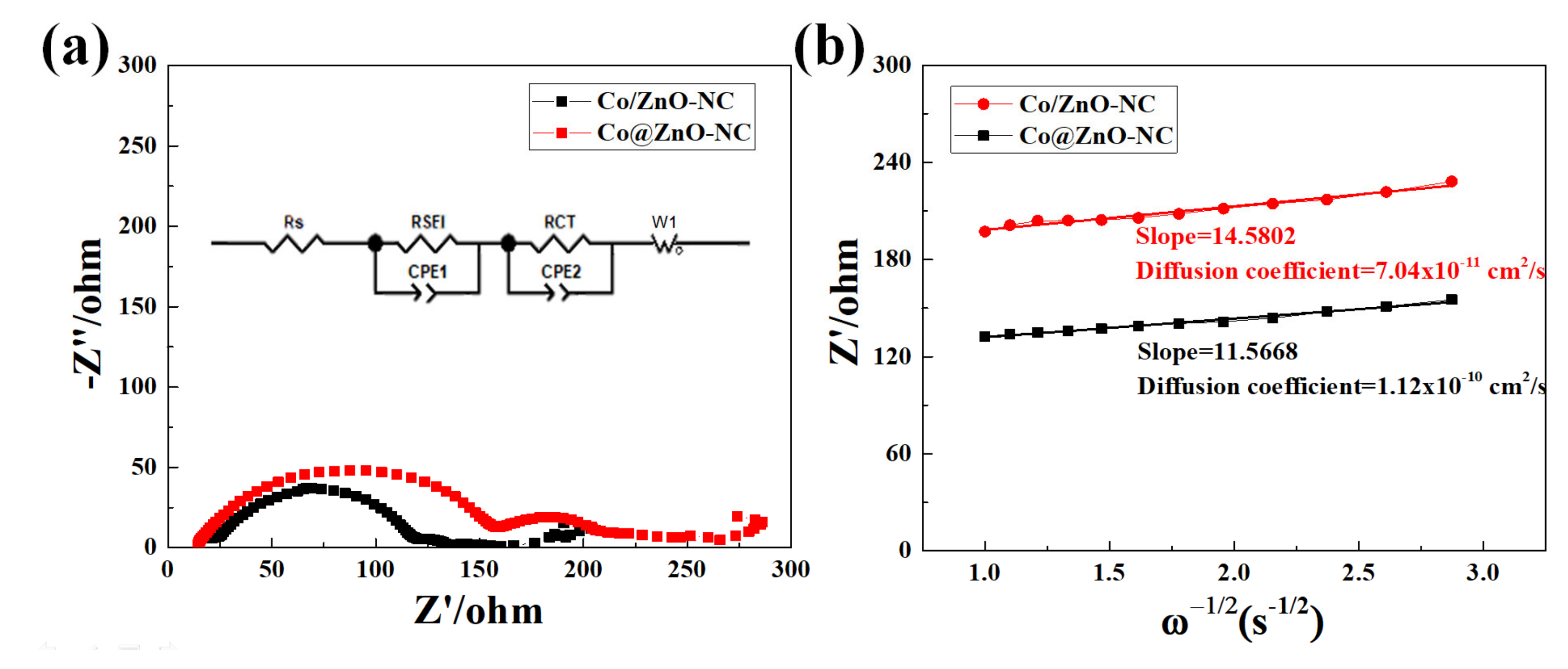
2.6. Electrochemical Measurements

The electrochemical behavior of the samples was examined using CR2032 coin cells. Pure lithium metal was used as a counter electrode. The working electrode comprised 80 wt.% active material, 10 wt.% super P (carbon black from Taiwan Maxwave Co., Ltd., Taipei City, Taiwan), and 10 wt.% polyvinylidene fluoride. The obtained mixture was dispersed in N-methyl pyrrolidine solution to form a homogeneous slurry. Subsequently, the slurry was pouched onto 10-μm copper foil and dried for 8 h at 120 °C in a vacuum oven. The electrolytes were 1 M LiPF6 in 30 wt.% ethylene carbonate and 58 wt.% diethyl carbonate with 2 wt.% vinylene carbonate and 10 wt.% fluoroethylene carbonate. The cells were assembled in a glove box filled with argon, and the H2O and O2 concentrations were <0.5 ppm. The separators used were of type Celgard 2325. The discharge/charge test results were analyzed using an AcuTech system operated at room temperature and at a voltage window of 0.01 V and 3 V. The electrochemical performance of the working electrodes was investigated through CV (CH Instruments Analyzer CHI 6273E) at a voltage window of 0.01 to 3 V and a scan rate of 0.1 mV·s1. Electrochemical impedance spectroscopy measurements were conducted using a CH Instruments Analyzer (CHI 6273E) at a perturbation amplitude of 5 mV and frequency range of 105 Hz to 10 mHz.

3. Results and Discussion

Figure 1 presents a schematic of the method for synthesizing porous Co/ZnO-NC and Co@ZnO-NC polyhedral nanostructures. We used ZIF-8 and ZIF-67 as precursors because they have the same topological structure and can be combined with metal cations coordinated with 2-methylimidazole. As indicated previously in this study, we proposed two structural designs of Co@ZnO-NC and Co/ZnO-NC composites. For the Co@ZnO-NC composite, core–shell nanostructures were prepared using a seed-mediated growth method. Subsequently, calcining was conducted for 4 h in an Ar atmosphere at 800 °C. The Co/ZnO-NC composite nanostructures were prepared using Zn(NO3)2·6H2O, Co(NO3)2·6H2O, and 2-methyl imidazole mixed with methanol; calcining was performed under the Ar atmosphere at 800 °C for 4 h.
The crystal phase structures of the ZIF-8@ZIF-67 and ZIF-8/ZIF-67 composites are presented as XRD patterns (Figure 2). The diffraction peaks (2θ) of 7.31°, 10.57°, 12.85°, 14.88°, 16.72°, and 18.3° corresponded to the peaks of (100), (002), (112), (022), (013), and (222), respectively. The XRD patterns of ZIF-8@ZIF-67 and ZIF-8/ZIF-67 matched the simulated patterns of ZIF-8 (JCPDS-62-1032) and ZIF-67(CCDC-671073), respectively. The strong and sharp profiles of these diffraction peaks confirmed high crystallinity. Figure 2 presents the XRD patterns of Co/ZnO-NC. The diffraction peaks (2θ) of 44.2°, 51.6°, and 75.9° corresponded to the peaks of (111), (200), and (220), respectively. The results indicated that Co (Marked by red star) was produced after the calcination of ZIF-8/ZIF-67. The broad peak at approximately 26° was attributed to the (002) peak of graphitic carbon.
Figure 3 and Figure 4 show SEM images and the corresponding EDS mapping of Co, Zn, and C for Co/ZnO-NC and Co@ZnO-NC, respectively. As shown in Figure 3, Co and Zn were homogeneously distributed in carbon matrix. Due to the composite-type Co/ZnO-NC structure, there was no obvious aggregation in Figure 3a. Figure 4a displays the surface morphology of core-shell type Co@ZnO-NC sample. More aggregated particles with the particle size of ~10 mm was observed in Figure 4a. Compared to Figure 3b, the signal of Co was more obvious for Co/ZnO-NC sample. It was due to the core-shell structure was successfully constructed by our process. The elemental distribution of Zn and C of Co/ZnO-NC and Co/ZnO-NC are shown in Figure 3c and Figure 3d, respectively. Both Zn and C were also well-distributed in these two composite. The results of Figure 4b–d supported that Co@ZnO was homogeneously embedded into carbon matrix.
Figure 5a,b presented the nitrogen adsorption/desorption isotherms and pore size distributions of as-synthesized Co/ZnO-NC and Co@ZnO-NC composites. As indicated in Figure 5a, the Co/ZnO-NC sample had typical type IV features with a distinct hysteresis loop at a high P/P0 of 0.4–1.0. The average pore size of Co/ZnO-NC composite was 3.87 nm. The average pore size of Co@ZnO-NC was 3.04 nm, and the specific surface area was 177.03 m2/g. These findings indicated the existence of many micropores and mesopores in these materials. The specific surface area of Co/ZnO-NC was 350.53 m2/g; it had a larger specific surface area and more mesopores than Co@ZnO-NC. The large specific surface area of the mesoporous structure was conducive to adaption to volumetric changes caused by Li ion extraction and insertion; therefore, the Co/ZnO-NC composite may provide more active sites for lithium storage compared with the Co@ZnO-NC composite.
An XPS survey of the Co/ZnO-NC composite, as indicated in Figure 6a, was conducted to identify its surface composition and oxidation state. The results confirmed the presence of C, N, O, Co, and Zn. A high-resolution XPS spectrum of the Co/ZnO-NC composite for C 1s is displayed in Figure 6b. The spectrum could be deconvoluted into four bands as follows: C-H/C-C/C=C at 284.6 eV, C-O at 286.2 eV, C=N at 285.7 eV, and O-C=O at 289.6 eV. The O 1s spectrum, as indicated in Figure 6c, exhibited three oxygen bonding features. The peak at 531.5 eV was typical of a metal–oxygen bond, and the peak at 532.9 eV was associated with oxygen-functionalized carbon, chemisorbed oxygen, and under-coordinated lattice oxygen. This result indicated that the oxidation process induced the formation of metal oxides and a disordered carbon phase. The N 1s spectrum presented in Figure 6d could be deconvoluted into three peaks at 398.5, 399.8, and 401.2 eV, corresponding to pyridinic, pyrrolic, and graphitic N atoms, respectively. The proportions of pyridinic, pyrrolic, and graphitic N in Co/ZnO-NC were 33.4%, 32.8%, and 33.7%, respectively. N atoms originating from imidazole moieties were doped into the composite. In addition, pyridinic N atoms were strongly set on both graphitic carbon and metal atoms, thus considerably improving structural stability. The peaks of Zn 2p, as presented in Figure 6e, exhibited two obvious bands at 1021.7 and 1044.7 eV, which could be assigned to Zn 2p3/2 and Zn 2p1/2, respectively. This result suggested that Zn in the composites was converted to ZnO. For Co 2p, as shown in Figure 6f, two distinct peaks were observed at 779.5 and 796.2 eV. These two peaks could be assigned to Co0 [39]. This result confirmed that N doping into the carbon frameworks of Co/ZnO-NC was achieved; this achievement is expected to improve the electrochemical performance of LIBs.
Figure 7a,b presented the representative SEM images of Co/ZnO-NC and Co@ZnO-NC. As indicated, both powders were aggregates; however, their surfaces still had many fiber-like structures on the surface. According to the literature [39], in the presence of inert gases, Co nanoparticles can act as a catalyst for CNTs (carbon nanotubes) production. CNTs can be generated in situ under the catalytic effect of cobalt nanoparticles at a high temperature and with sufficient partial pressure of Ar. TEM images of Co/ZnO-NC and Co@ZnO-NC are presented in Figure 7c,d, respectively. The insets of Figure 7c,d display the corresponding selected area electron diffraction patterns. Figure 7c indicates that the diffraction rings of Co/ZnO-NC conformed to the (220), (111), and (110) planes of Co and with the (400) planes of ZnO. Figure 7d reveals that the diffraction rings of Co/ZnO-NC are in favorable agreement with the (220), (111), and (110) planes of Co. The results related to Co@ZnO-NC indicated that Co was encapsulated on the surface of Co@ZnO-NC composite. These crystal planes of the composite match the XRD measurements presented in Figure 2. The TEM images of Co/ZnO-NC composite indicated that the Co and ZnO-NC were mixed homogeneously. Many small tubular fibers formed around the structure of the composite, a finding that is consistent with the SEM results. The carbon nanotubes growing on the surface of the Co/ZnO-NC composite may increase its surface area and facilitate the rapid migration of lithium ions, effectively improving the electrochemical performance of LIBs.
Figure 8a,b presented the charge/discharge curves of Co@ZnO-NC and Co/ZnO-NC samples at a current density of 200 mA/g over 100 cycles. The discharge capacity of Co@ZnO-NC at the 1st, 2nd, 3rd, 5th, 10th, 20th, 50th, 75th, and 100th cycle was 836, 485, 450, 430, 393, 359, 353, and 363 mAh/g, respectively. The corresponding charge capacity at the 1st, 2nd, 3rd, 5th, 10th, 20th, 50th, 75th, and 100th cycle was 482, 457, 438, 418, 385, 356, 350, and 361 mAh/g, respectively. The corresponding Coulombic efficiency of Co@ZnO-NC was 57%, 94%, 97%, 97%, 97%, 99%, 100%, and 99% at the 1st, 2nd, 3rd, 5th, 10th, 20th, 50th, 75th, and 100th cycle, respectively. The discharge capacity of Co/ZnO-NC at the 1st, 2nd, 3rd, 5th, 10th, 20th, 50th, 75th, and 100th cycle was 989, 550, 528, 523, 496, 454, 354, and 266 mAh/g, respectively. The charge capacity of Co/ZnO-NC at the 1st, 2nd, 3rd, 5th, 10th, 20th, 50th, 75th, and 100th cycle was 548, 519, 516, 512, 490, 450, 348, and 267 mAh/g, respectively. The Coulombic efficiency of Co/ZnO-NC was 55%, 94%, 97%, 97%, 98%, 99%, 98%, and 100% at the 1st, 2nd, 3rd, 5th, 10th, 20th, 50th, 75th, and 100th cycle, respectively. A large irreversible capacity at the first cycle was ascribed to the solid electrolyte interface layer (SEI) and the initial irreversible reactions of the active materials. Figure 8c shows the cycling stability of the Co@ZnO-NC and Co/ZnO-NC for 100 cycles at 200 mA/g. Both exhibited stable cycle stability during the first 50 cycles. The discharge/charge capacities of Co@ZnO-NC and Co/ZnO-NC after 100 cycles were 411 and 246 mAh/g, respectively. The capacity of Co@ZnO-NC slightly decreased from 498 mAh/g to 246 mAh/g after 100 cycles, presumably because the damage to the internal structure was more severe compared to Co@ZnO-NC composite. In the first cycle, the Coulombic efficiency of Co/ZnO-NC was as low as 52%; this could be ascribed to the chemical reaction of the electrolyte and the formation of the SEI layer. The capacity retention rates of Co@ZnO-NC and Co/ZnO-NC were 49% and 82%, respectively. Figure 8d reveals that the rate performance levels of Co/ZnO-NC and Co@ZnO-NC were measured at the current densities of 0.1, 0.2, 0.5, 1, 2, 5, and 10 A/g before the current density was reverted to 0.1 A/g. Co/ZnO-NC had an average specific capacity of 572, 548, 503, 460, 417, 345, 257, and 567 mAh/g, respectively, and Co@ZnO-NC had an average specific capacity of 531, 455, 350, 276, 207, 117, 52, and 476 mAh/g, respectively. Unlike the Co/ZnO-NC electrode, the reversible specific capacity of Co@ZnO-NC decreased as the current density increased. This further demonstrated that Co/ZnO-NC is superior to Co@ZnO-NC as an anode for LIBs. The superior conductivity and abundant porous channels of Co/ZnO-NC may provide an intrinsic guarantee of the fast transport of electrons and Li+ within electrodes.
Figure 9a presents AC impedance measurement results for Co/ZnO-NC and Co@ZnO-NC electrodes; these measurements were undertaken to understand these electrodes’ lithium storage properties. Each Nyquist plot can be approximately divided into many sections. The high-frequency intercept on the axis represents electrolyte resistance (Rs). The depressed semicircle at medium frequencies generally relates to charge transfer resistance (RCT), the SEI (Solid electrolyte interphase) layer (RSEI), and the slope at a low frequency represents Warburg impedance in relation to the diffusion of the lithium ion process [45]. The larger the diameter of the semicircle is, the greater is the charge transfer resistance. The fitting result is shown in Table 1. The RSEI of Co@ZnO-NC and Co/ZnO-NC was 144 Ω and 97 Ω, respectively. The RCT of Co@ZnO-NC and Co/ZnO-NC was 49 Ω and 15 Ω, respectively. The RCT and RSEI of the Co/ZnO-NC were considerably smaller than those of Co@ZnO-NC, indicating that Co/ZnO-NC electrodes have smaller resistance than core–shell electrodes. As indicated in Figure 7b, the Li ion diffusion coefficient of these two samples can be calculated using the following equation:
D Li = R 2 T 2 2 A 2 n 4 F 4 C 2 σ 2
where DLi+ is the diffusion coefficient of lithium ion. R (8.314 J/mol × K) is the gas constant, T is the absolute temperature (298.15 K in the present study), n is the number of electrons per molecule during oxidization (n = 1), F (96,485.3 C mol−1) is the Faraday’s constant, A is the area of the anode/electrolyte interface, C (0.001 mol cm3) is the concentration of lithium ions, and σ is the Warburg factor, which is related to Zre [46]. Using slope values σ, as shown in Figure 9b, the diffusion coefficients of Co/ZnO-NC and Co@ZnO-NC were determined to be 7.04 × 10⁻¹¹ and 1.12 × 10⁻¹⁰ cm2/s, respectively. The results indicated that the Co/ZnO-NC electrode had higher Li ion diffusivity than did the other electrode. These results confirmed the excellent cycling stability and electrical conductivity of Co/ZnO-NC composites.
Figure 10a,b showed the SEM images of Co/ZnO-NC electrodes before and after cycling tests, respectively. As shown in the SEM images, even for 100 cycles, the surface morphology of Co/ZnO-NC electrode remained condense structure without cracking. The result indicated that composite-type Co/ZnO-NC demonstrate an excellent structural stability during charge and discharge processes.
Figure 11 presents a schematic of the charge and discharge process of Co/ZnO-NC and Co@ZnO-NC. Co@ZnO-NC expanded and shrank after many charge and discharge cycles such that the cobalt covered by the outer layer collapsed, resulting in poor electrochemical properties. The structure of Co/ZnO-NC was not covered, and its structural composition was not altered during charge and discharge processes. The electrochemical performance of Co/ZnO-NC was more favorable than that of Co@ZnO-NC.

4. Conclusions

In this study, two blending methods and high-temperature sintering were used to produce Co/ZnO-NC and Co@ZnO-NC. The porous structure of MOFs is conducive to Li ion transfer, and a high temperature enabled the production of nitrogen-doped carbon and fibrous carbon nanotubes on the surfaces of these materials. Electrical analyses demonstrated that Co/ZnO-NC exhibited higher cycling stability and reversible capacity than Co@ZnO-NC. According to the rate capability tests, Co/ZnO-NC exhibited higher rate capability. The diffusion coefficients of lithium ions in Co/ZnO-NC and Co@ZnO-NC were 7.04 × 10¹¹ and 1.12 × 1010 cm2/s, respectively. High electrochemical performance can be obtained by blending ZIF-67 and ZIF-8 precursors. The results revealed that the Co/ZnO-NC composite is a potential anode material for LIBs.

Author Contributions

Y.-C.C. wrote the paper; W.-R.L. conceived and designed the experiments; C.-H.H. analyzed the data. All authors have read and agreed to the published version of the manuscript.

Funding

This research was funded by Ministry of Science and Technology [MOST 109-2923-E-006-006, 110-2622-M-033-001, 109-2622-E-033-010, 110-2923-E-006-011, 110-3116-F-011-002, 111-2221-E-033-004-MY3 and 108-E-033-MY3].

Institutional Review Board Statement

Not applicable.

Informed Consent Statement

Not applicable.

Data Availability Statement

Not applicable.

Acknowledgments

The authors gratefully acknowledge the Ministry of Science and Technology, Taiwan, project grants of numbers MOST 109-2923-E-006-006, 110-2622-M-033-001, 109-2622-E-033-010, 110-2923-E-006-011, 110-3116-F-011-002, 111-2221-E-033-004-MY3 and 108-E-033-MY3.

Conflicts of Interest

The authors declare no conflict of interest.

References

  1. Hassoun, J.; Panero, S.; Reale, P.; Scrosati, B. A new, safe, high-rate and high-energy polymer lithium-ion battery. Adv. Mater. 2009, 21, 4807–4810. [Google Scholar] [CrossRef] [PubMed]
  2. Yoshino, A. The birth of the lithium-ion battery. Angew. Chem. Int. Ed. 2012, 51, 5798–5800. [Google Scholar] [CrossRef] [PubMed]
  3. Liu, H.K.; Wang, G.X.; Guo, Z.; Wang, J.; Konstantinov, K. Nanomaterials for lithium-ion rechargeable batteries. J. Nanosci. Nanotechnol. 2006, 6, 1–15. [Google Scholar] [CrossRef] [PubMed]
  4. Manthiram, A. An outlook on lithium ion battery technology. ACS Cent. Sci. 2017, 3, 1063–1069. [Google Scholar] [CrossRef] [Green Version]
  5. Zhang, H.; Zhou, L.; Yu, C. Highly crystallized Fe2O3 nanocrystals on graphene: A lithium ion battery anode material with enhanced cycling. RSC Adv. 2013, 4, 495–499. [Google Scholar] [CrossRef] [Green Version]
  6. Lian, P.; Zhu, X.; Xiang, H.; Li, Z.; Yang, W.; Wang, H. Enhanced cycling performance of Fe3O4–graphene nanocomposite as an anode material for lithium-ion batteries. Electrochim. Acta 2010, 56, 834–840. [Google Scholar] [CrossRef]
  7. Wang, B.; Côté, A.P.; Furukawa, H.; O’Keeffe, M.; Yaghi, O.M. Colossal cages in zeolitic imidazolate frameworks as selective carbon dioxide reservoirs. Nature 2008, 453, 207–211. [Google Scholar] [CrossRef]
  8. Fairen-Jimenez, D.; Moggach, S.; Wharmby, M.; Wright, P.; Parsons, S.; Duren, T. Opening the gate: Framework flexibility in ZIF-8 explored by experiments and simulations. J. Am. Chem. Soc. 2011, 133, 8900–8902. [Google Scholar] [CrossRef] [Green Version]
  9. Li, H.; Eddaoudi, M.; O’Keeffe, M.; Yaghi, O.M. Design and synthesis of an exceptionally stable and highly porous metal-organic framework. Nature 1999, 402, 276–279. [Google Scholar] [CrossRef] [Green Version]
  10. Mu, L.; Liu, B.; Liu, H.; Yang, Y.; Sun, C.; Chen, G. A novel method to improve the gas storage capacity of ZIF-8. J. Mater. Chem. 2012, 22, 12246–12252. [Google Scholar] [CrossRef]
  11. Hu, Y.; Liu, Z.; Xu, J.; Huang, Y.; Song, Y. Evidence of pressure enhanced CO2 storage in ZIF-8 probed by FTIR spectroscopy. J. Am. Chem. Soc. 2013, 135, 9287–9290. [Google Scholar] [CrossRef]
  12. Liu, D.; Ma, X.; Xi, H.; Lin, Y. Gas transport properties and propylene/propane separation characteristics of ZIF-8 membranes. J. Membr. Sci. 2014, 451, 85–93. [Google Scholar] [CrossRef]
  13. Kumar, R.; Jayaramulu, K.; Maji, T.K.; Rao, C. Hybrid nanocomposites of ZIF-8 with graphene oxide exhibiting tunable morphology, significant CO 2 uptake and other novel properties. Chem. Commun. 2013, 49, 4947–4949. [Google Scholar] [CrossRef]
  14. McEwen, J.; Hayman, J.-D.; Yazaydin, A.O. A comparative study of CO2, CH4 and N2 adsorption in ZIF-8, Zeolite-13X and BPL activated carbon. Chem. Phys. 2013, 412, 72–76. [Google Scholar] [CrossRef]
  15. Zhang, Z.; Xian, S.; Xi, H.; Wang, H.; Li, Z. Improvement of CO2 adsorption on ZIF-8 crystals modified by enhancing basicity of surface. Chem. Eng. Sci. 2011, 66, 4878–4888. [Google Scholar] [CrossRef]
  16. Thomas, A.; Ahamed, R.; Prakash, M. Selection of a suitable ZIF-8/ionic liquid (IL) based composite for selective CO 2 capture: The role of anions at the interface. RSC Adv. 2020, 10, 39160–39170. [Google Scholar] [CrossRef]
  17. Feng, S.; Zhang, X.; Shi, D.; Wang, Z. Zeolitic imidazolate framework-8 (ZIF-8) for drug delivery: A critical review. Front. Chem. Sci. Eng. 2021, 15, 221–237. [Google Scholar] [CrossRef]
  18. Zheng, C.; Wang, Y.; Phua, S.Z.F.; Lim, W.Q.; Zhao, Y. ZnO–DOX@ ZIF-8 core–shell nanoparticles for pH-responsive drug delivery. ACS Biomater. Sci. Eng. 2017, 3, 2223–2229. [Google Scholar] [CrossRef]
  19. Sun, C.-Y.; Qin, C.; Wang, X.-L.; Yang, G.-S.; Shao, K.-Z.; Lan, Y.-Q.; Su, Z.-M.; Huang, P.; Wang, C.-G.; Wang, E.-B. Zeolitic imidazolate framework-8 as efficient pH-sensitive drug delivery vehicle. Dalton Trans. 2012, 41, 6906–6909. [Google Scholar] [CrossRef]
  20. Kaur, H.; Mohanta, G.C.; Gupta, V.; Kukkar, D.; Tyagi, S. Synthesis and characterization of ZIF-8 nanoparticles for controlled release of 6-mercaptopurine drug. J. Drug Deliv. Sci. Technol. 2017, 41, 106–112. [Google Scholar] [CrossRef]
  21. Ren, H.; Zhang, L.; An, J.; Wang, T.; Li, L.; Si, X.; He, L.; Wu, X.; Wang, C.; Su, Z. Polyacrylic acid@ zeolitic imidazolate framework-8 nanoparticles with ultrahigh drug loading capability for pH-sensitive drug release. Chem. Commun. 2014, 50, 1000–1002. [Google Scholar] [CrossRef] [PubMed]
  22. Bux, H.; Chmelik, C.; Krishna, R.; Caro, J. Ethene/ethane separation by the MOF membrane ZIF-8: Molecular correlation of permeation, adsorption, diffusion. J. Membr. Sci. 2011, 369, 284–289. [Google Scholar] [CrossRef]
  23. Hara, N.; Yoshimune, M.; Negishi, H.; Haraya, K.; Hara, S.; Yamaguchi, T. Diffusive separation of propylene/propane with ZIF-8 membranes. J. Membr. Sci. 2014, 450, 215–223. [Google Scholar] [CrossRef]
  24. Lai, Z. Development of ZIF-8 membranes: Opportunities and challenges for commercial applications. Curr. Opin. Chem. Eng. 2018, 20, 78–85. [Google Scholar] [CrossRef] [Green Version]
  25. Huang, H.; Zhang, W.; Liu, D.; Liu, B.; Chen, G.; Zhong, C. Effect of temperature on gas adsorption and separation in ZIF-8: A combined experimental and molecular simulation study. Chem. Eng. Sci. 2011, 66, 6297–6305. [Google Scholar] [CrossRef]
  26. Dai, H.; Xia, B.; Wen, L.; Du, C.; Su, J.; Luo, W.; Cheng, G. Synergistic catalysis of AgPd@ ZIF-8 on dehydrogenation of formic acid. Appl. Catal. B Environ. 2015, 165, 57–62. [Google Scholar] [CrossRef]
  27. Kuo, C.-H.; Tang, Y.; Chou, L.-Y.; Sneed, B.T.; Brodsky, C.N.; Zhao, Z.; Tsung, C.-K. Yolk–shell nanocrystal@ ZIF-8 nanostructures for gas-phase heterogeneous catalysis with selectivity control. J. Am. Chem. Soc. 2012, 134, 14345–14348. [Google Scholar] [CrossRef]
  28. Chizallet, C.; Lazare, S.; Bazer-Bachi, D.; Bonnier, F.; Lecocq, V.; Soyer, E.; Quoineaud, A.-A.; Bats, N. Catalysis of transesterification by a nonfunctionalized metal−organic framework: Acido-basicity at the external surface of ZIF-8 probed by FTIR and ab initio calculations. J. Am. Chem. Soc. 2010, 132, 12365–12377. [Google Scholar] [CrossRef]
  29. Sisi, A.J.; Fathinia, M.; Khataee, A.; Orooji, Y. Systematic activation of potassium peroxydisulfate with ZIF-8 via sono-assisted catalytic process: Mechanism and ecotoxicological analysis. J. Mol. Liq. 2020, 308, 113018. [Google Scholar] [CrossRef]
  30. Zhu, M.; Srinivas, D.; Bhogeswararao, S.; Ratnasamy, P.; Carreon, M.A. Catalytic activity of ZIF-8 in the synthesis of styrene carbonate from CO2 and styrene oxide. Catal. Commun. 2013, 32, 36–40. [Google Scholar] [CrossRef]
  31. Dang, T.T.; Zhu, Y.; Ngiam, J.S.; Ghosh, S.C.; Chen, A.; Seayad, A.M. Palladium nanoparticles supported on ZIF-8 as an efficient heterogeneous catalyst for aminocarbonylation. ACS Catal. 2013, 3, 1406–1410. [Google Scholar] [CrossRef]
  32. Li, B.; Wen, H.M.; Cui, Y.; Zhou, W.; Qian, G.; Chen, B. Emerging multifunctional metal–organic framework materials. Adv. Mater. 2016, 28, 8819–8860. [Google Scholar] [CrossRef]
  33. Phan, A.; Doonan, C.J.; Uribe-Romo, F.J.; Knobler, C.B.; O’Keeffe, M.; Yaghi, O.M. Synthesis, structure, and carbon dioxide capture properties of zeolitic imidazolate frameworks. Acc. Chem. Res. 2009, 43, 58–67. [Google Scholar] [CrossRef]
  34. Lee, Y.-R.; Jang, M.-S.; Cho, H.-Y.; Kwon, H.-J.; Kim, S.; Ahn, W.-S. ZIF-8: A comparison of synthesis methods. Chem. Eng. J. 2015, 271, 276–280. [Google Scholar] [CrossRef]
  35. Tai, Z.; Shi, M.; Chong, S.; Chen, Y.; Shu, C.; Dai, X.; Tan, Q.; Liu, Y. N-doped ZIF-8-derived carbon (NC-ZIF) as an anodic material for lithium-ion batteries. J. Alloys Compd. 2019, 800, 1–7. [Google Scholar] [CrossRef]
  36. Son, S.; Lim, D.; Nam, D.; Kim, J.; Shim, S.E.; Baeck, S.-H. N, S-doped nanocarbon derived from ZIF-8 as a highly efficient and durable electro-catalyst for oxygen reduction reaction. J. Solid State Chem. 2019, 274, 237–242. [Google Scholar] [CrossRef]
  37. Tang, J.; Salunkhe, R.R.; Liu, J.; Torad, N.L.; Imura, M.; Furukawa, S.; Yamauchi, Y. Thermal conversion of core–shell metal–organic frameworks: A new method for selectively functionalized nanoporous hybrid carbon. J. Am. Chem. Soc. 2015, 137, 1572–1580. [Google Scholar] [CrossRef]
  38. Cheng, E.; Huang, S.; Chen, D.; Huang, R.; Wang, Q.; Hu, Z.; Jiang, Y.; Li, Z.; Zhao, B.; Chen, Z. Porous ZnO/Co3O4/N-doped carbon nanocages synthesized via pyrolysis of complex metal–organic framework (MOF) hybrids as an advanced lithium-ion battery anode. Acta Crystallogr. Sect. C Struct. Chem. 2019, 75, 969–978. [Google Scholar] [CrossRef] [Green Version]
  39. Huang, M.; Mi, K.; Zhang, J.; Liu, H.; Yu, T.; Yuan, A.; Kong, Q.; Xiong, S. MOF-derived bi-metal embedded N-doped carbon polyhedral nanocages with enhanced lithium storage. J. Mater. Chem. A 2017, 5, 266–274. [Google Scholar] [CrossRef]
  40. Zhao, J.; Yao, S.; Hu, C.; Li, Z.; Wang, J.; Feng, X. Porous ZnO/Co3O4/CoO/Co composite derived from Zn-Co-ZIF as improved performance anodes for lithium-ion batteries. Mater. Lett. 2019, 250, 75–78. [Google Scholar] [CrossRef]
  41. Gao, C.; Jiang, Z.; Wang, P.; Jensen, L.R.; Zhang, Y.; Yue, Y. Optimized assembling of MOF/SnO2/Graphene leads to superior anode for lithium ion batteries. Nano Energy 2020, 74, 104868. [Google Scholar] [CrossRef]
  42. Gao, C.; Wang, P.; Wang, Z.; Kær, S.K.; Zhang, Y.; Yue, Y. The disordering-enhanced performances of the Al-MOF/graphene composite anodes for lithium ion batteries. Nano Energy 2019, 65, 104032. [Google Scholar] [CrossRef]
  43. Gao, C.; Jiang, Z.; Qi, S.; Wang, P.; Jensen, L.R.; Johansen, M.; Christensen, C.K.; Zhang, Y.; Ravnsbæk, D.B.; Yue, Y. Metal-organic framework glass anode with an exceptional cycling-induced capacity enhancement for Lithium-ion batteries. Adv. Mater. 2022, 34, 2110048. [Google Scholar] [CrossRef]
  44. Muruganantham, R.; Gu, Y.-J.; Song, Y.-D.; Kung, C.-W.; Liu, W.-R. Ce-MOF derived ceria: Insights into the Na-ion storage mechanism as a high-rate performance anode material. Appl. Mater. Today 2021, 22, 100935. [Google Scholar] [CrossRef]
  45. Wang, G.; Yang, J.; Park, J.; Gou, X.; Wang, B.; Liu, H.; Yao, J. Facile synthesis and characterization of graphene nanosheets. J. Phys. Chem. C 2008, 112, 8192–8195. [Google Scholar] [CrossRef]
  46. Tuccitto, N.; Riela, L.; Zammataro, A.; Spitaleri, L.; Li-Destri, G.; Sfuncia, G.; Nicotra, G.; Pappalardo, A.; Capizzi, G.; Trusso Sfrazzetto, G. Functionalized carbon nanoparticle-based sensors for chemical warfare agents. ACS Appl. Nano Mater. 2020, 3, 8182–8191. [Google Scholar] [CrossRef]
Figure 1. Schematic diagrams of (a) Co/ZnO-NC and (b) Co@ZnO-NC composite preparation.
Polymers 14 03085 g001
Figure 2. XRD patterns of ZIF-8, ZIF-67, ZIF-8@ZIF-67, ZIF-8/ZIF-67, Co/ZnO-NC, and Co. The red stars in the Figure is Co.
Polymers 14 03085 g002
Figure 3. (a) SEM and EDS mapping of (b) Co, (c) Zn, and (d) C of Co/ZnO-NC.
Polymers 14 03085 g003
Figure 4. (a) SEM and EDS mapping of (b) Co, (c) Zn, and (d) C of Co@ZnO-NC.
Polymers 14 03085 g004
Figure 5. (a) N2 adsorption isotherms and (b) pore size distributions of Co@ZnO-NC and Co/ZnO-NC.
Polymers 14 03085 g005
Figure 6. XPS spectra of Co/ZnO-NC: (a) survey scan spectrum, (b) high-resolution C 1s spectrum, (c) O 1s spectrum, (d) N 1s spectrum, (e) Zn 2p spectrum, and (f) Co 2p spectrum.
Polymers 14 03085 g006
Figure 7. (a) SEM and (c) TEM images of Co/ZnO-NC; (b) SEM and (d) TEM images of Co@ZnO-NC. Insets in (c,d) are the corresponding selected area electron diffraction patterns.
Polymers 14 03085 g007
Figure 8. Charge/discharge curves of (a) Co/ZnO-NC and (b) Co@ZnO-NC at 200 mA/g; (c) Cycling performance of Co@ZnO-NC and Co/ZnO-NC at 200 mA/g; (d) Rate performance of Co@ZnO-NC and Co/ZnO-NC.
Polymers 14 03085 g008
Figure 9. (a) Nyquist plots for Co@ZnO-NC and Co/ZnO-NC electrodes; (b) Corresponding Randles plots for Co@ZnO-NC and Co/ZnO-NC electrodes.
Polymers 14 03085 g009
Figure 10. SEM images of Co/ZnO-NC electrodes before (a) and after cycling (b).
Polymers 14 03085 g010
Figure 11. Schematic of Co/ZnO-NC and Co@ZnO-NC electrodes before and after discharge/charge tests.
Polymers 14 03085 g011
Table 1. RSEI, RCT, and diffusion coefficient of Li in Co/ZnO-NC and Co@ZnO-NC electrodes.
ComponentsCo/ZnO-NCCo@ZnO-NC
Rs (Ω)2318
RSEI (Ω)97144
RCT (Ω)1549
σ (Ω/s0.5)14.5811.56
D (cm2/s)7.04 × 10−111.12 × 10⁻¹⁰
Publisher’s Note: MDPI stays neutral with regard to jurisdictional claims in published maps and institutional affiliations.

