A Preliminary Study of the Influence of Graphene Nanoplatelet Specific Surface Area on the Interlaminar Fracture Properties of Carbon Fiber/Epoxy Composites


Abstract

1. Introduction
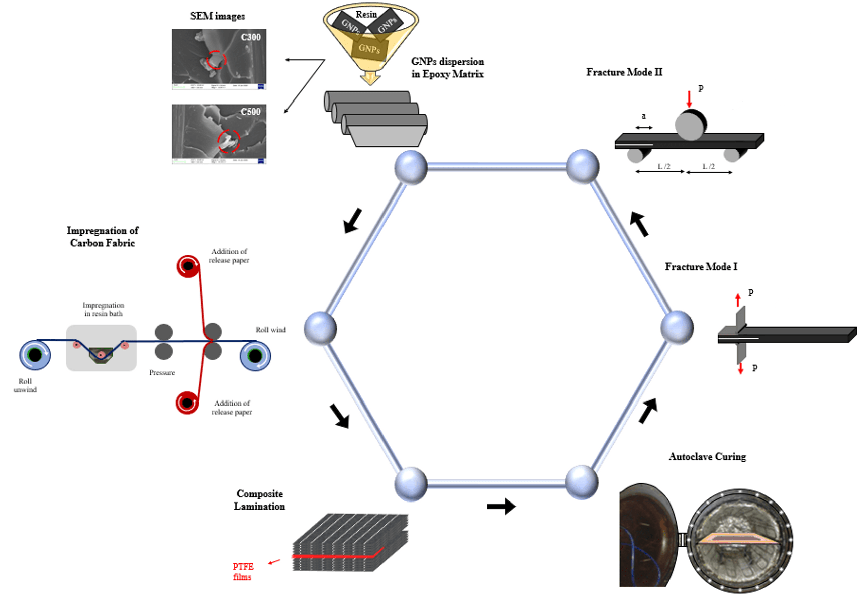
2. Materials and Methods
2.1. Materials
2.2. Preparation of the Nano-Modified Matrix
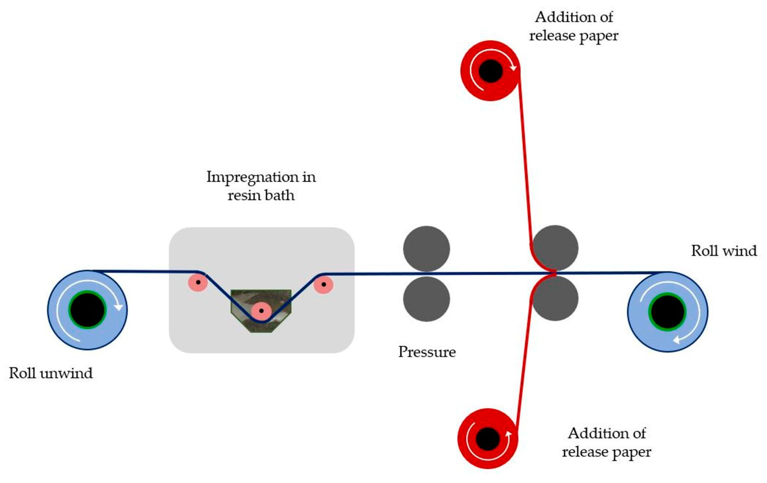
2.3. Prepreg Manufacturing Process
2.4. Preparation of Nano-Reinforced CFRP Laminates
3. Fracture Tests
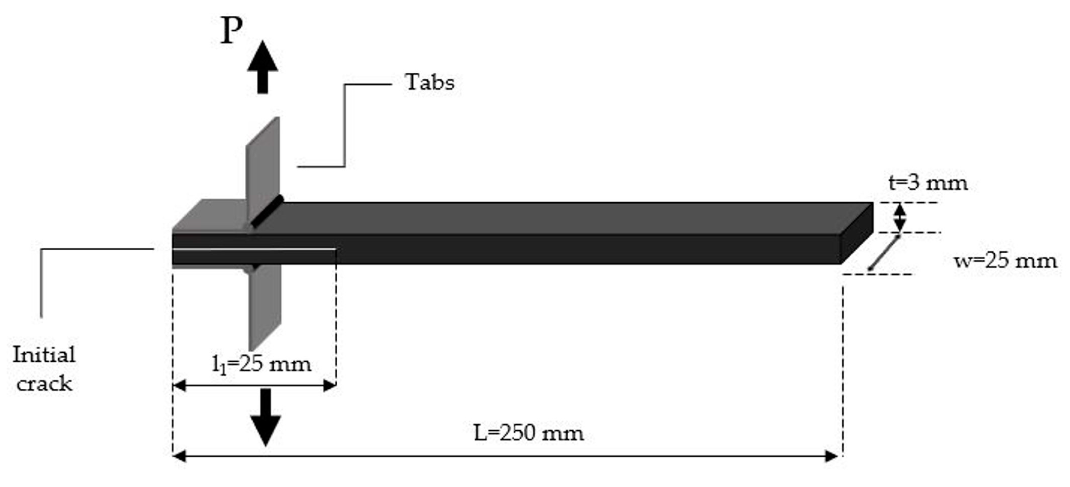
3.1. Mode I Test
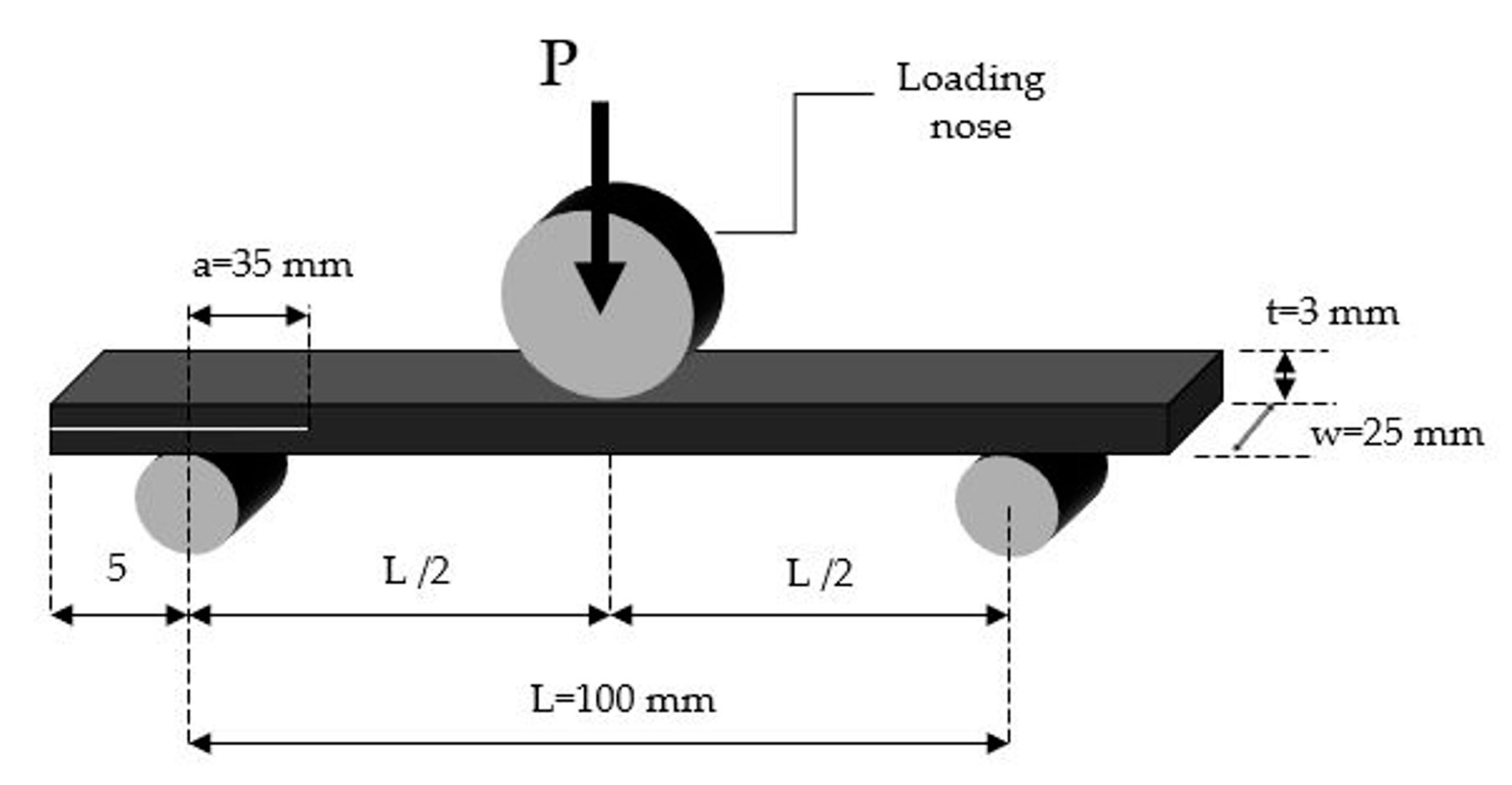
3.2. Mode II Test
4. Results and Discussion
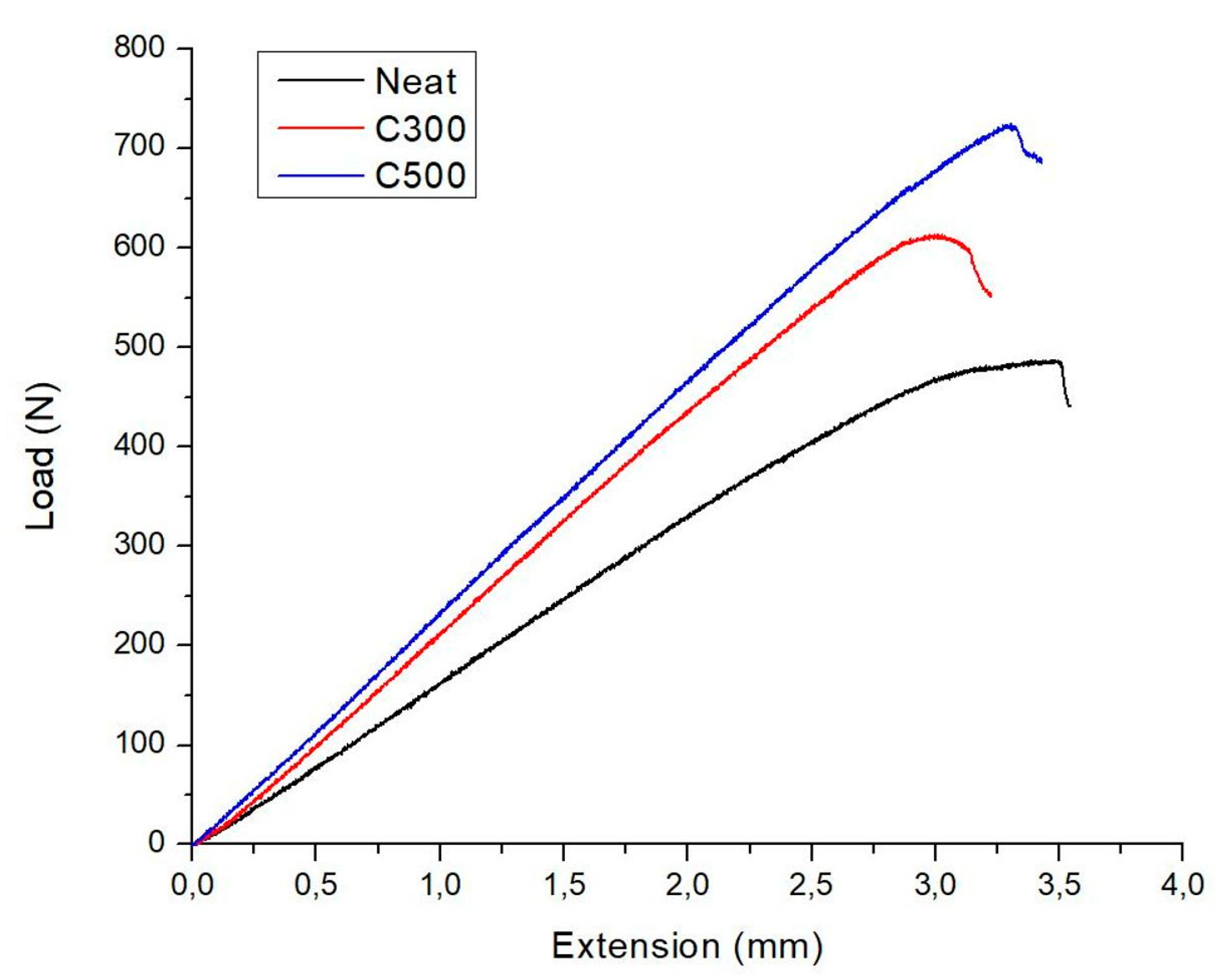
4.1. Fracture Properties Mode I
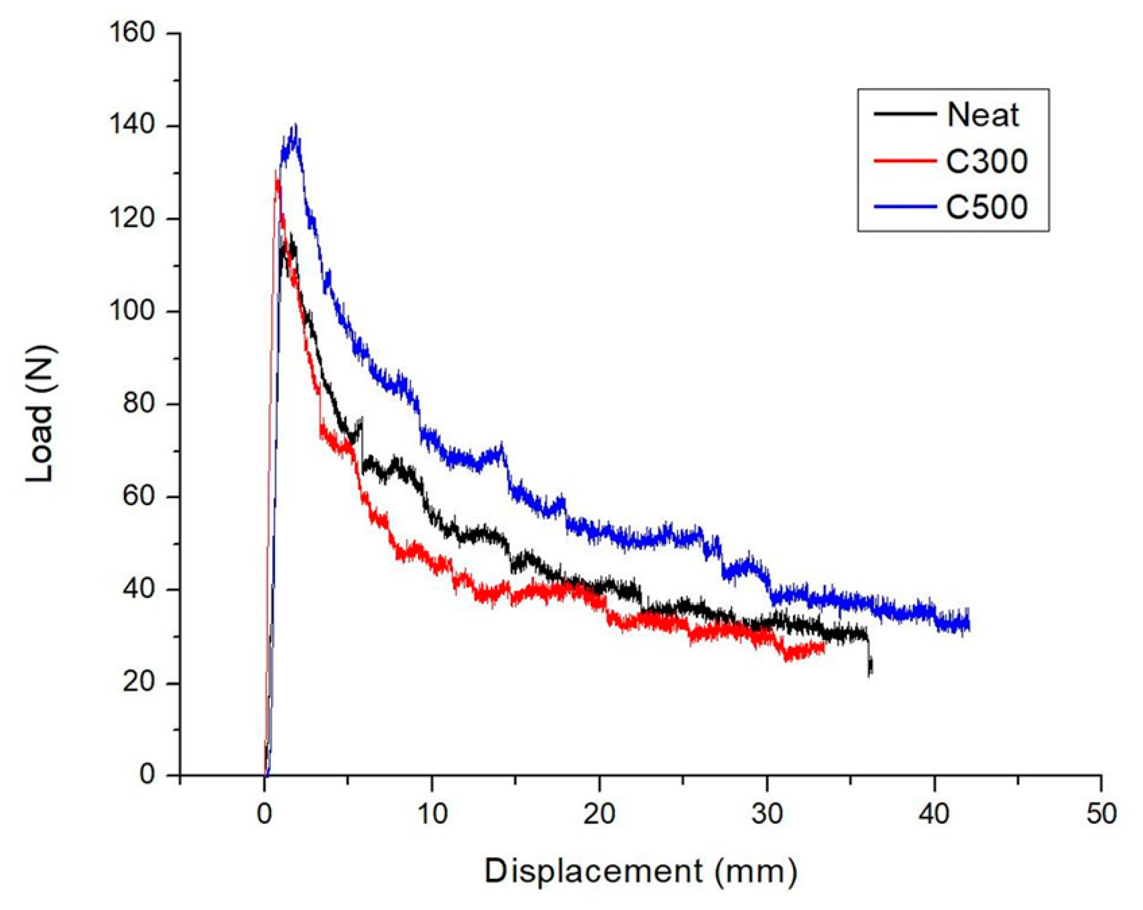
4.2. Fracture Properties Mode II
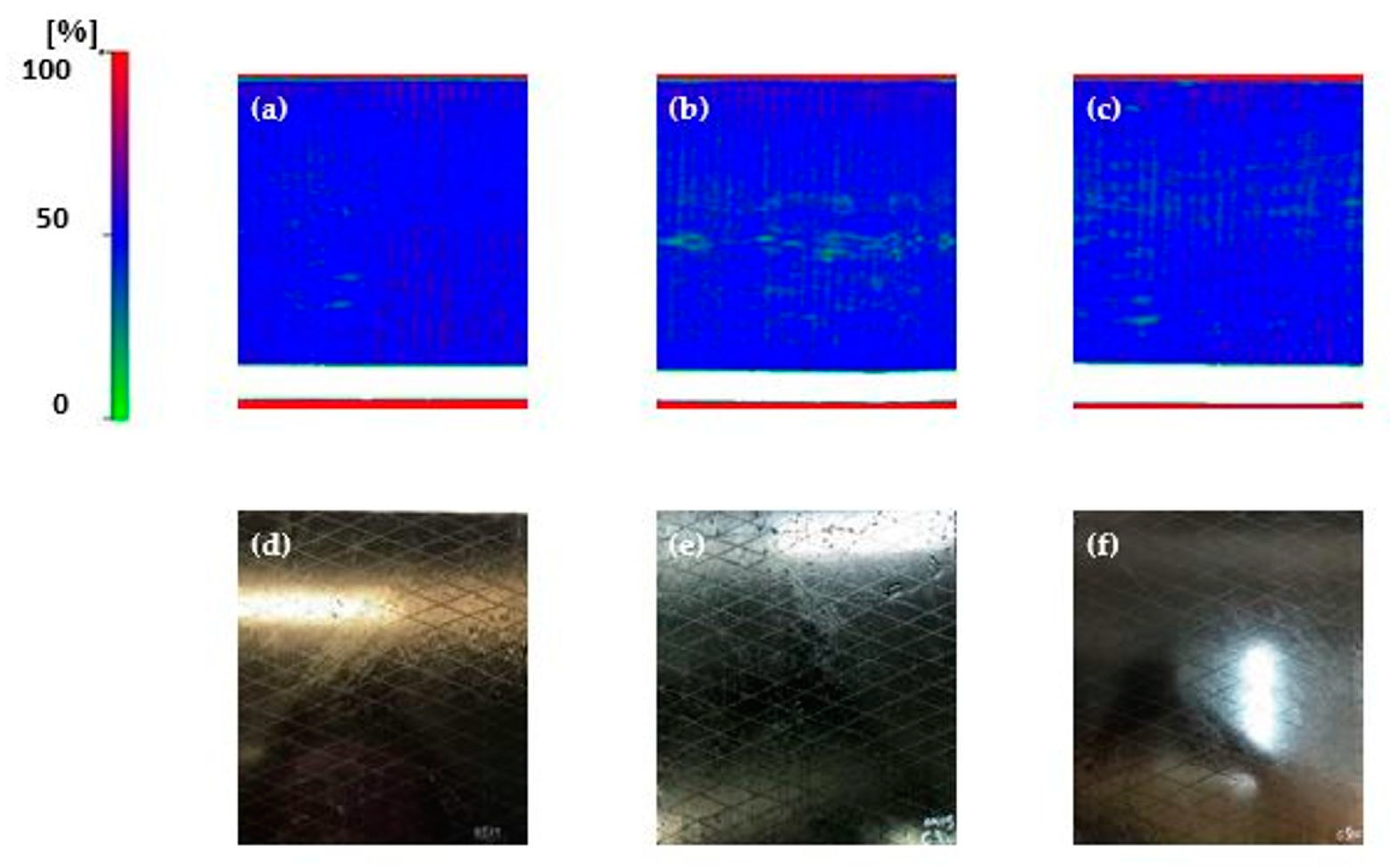
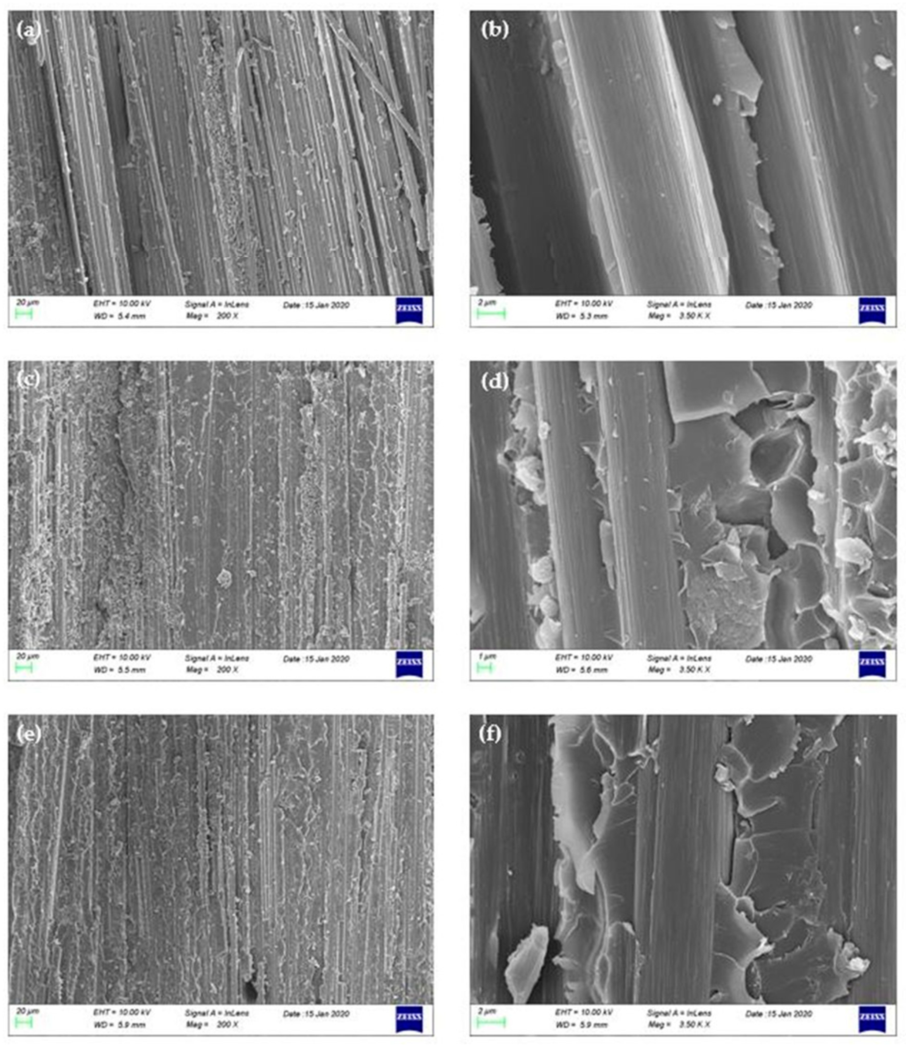
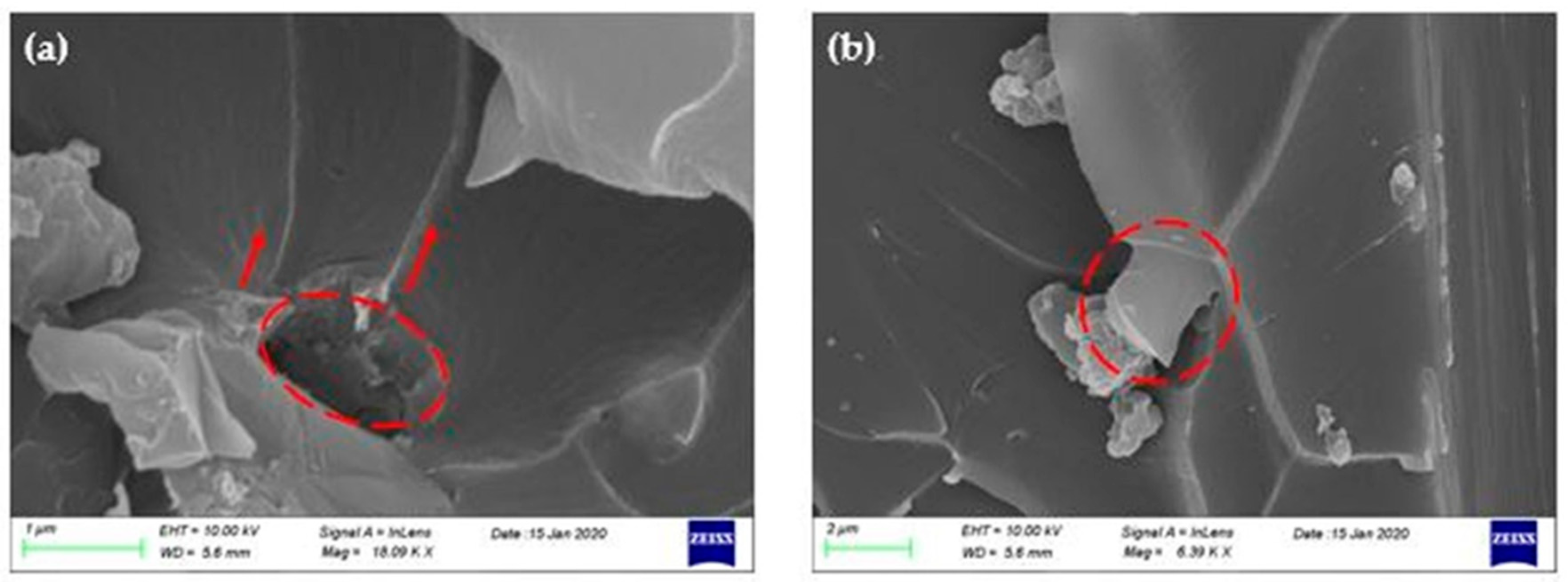
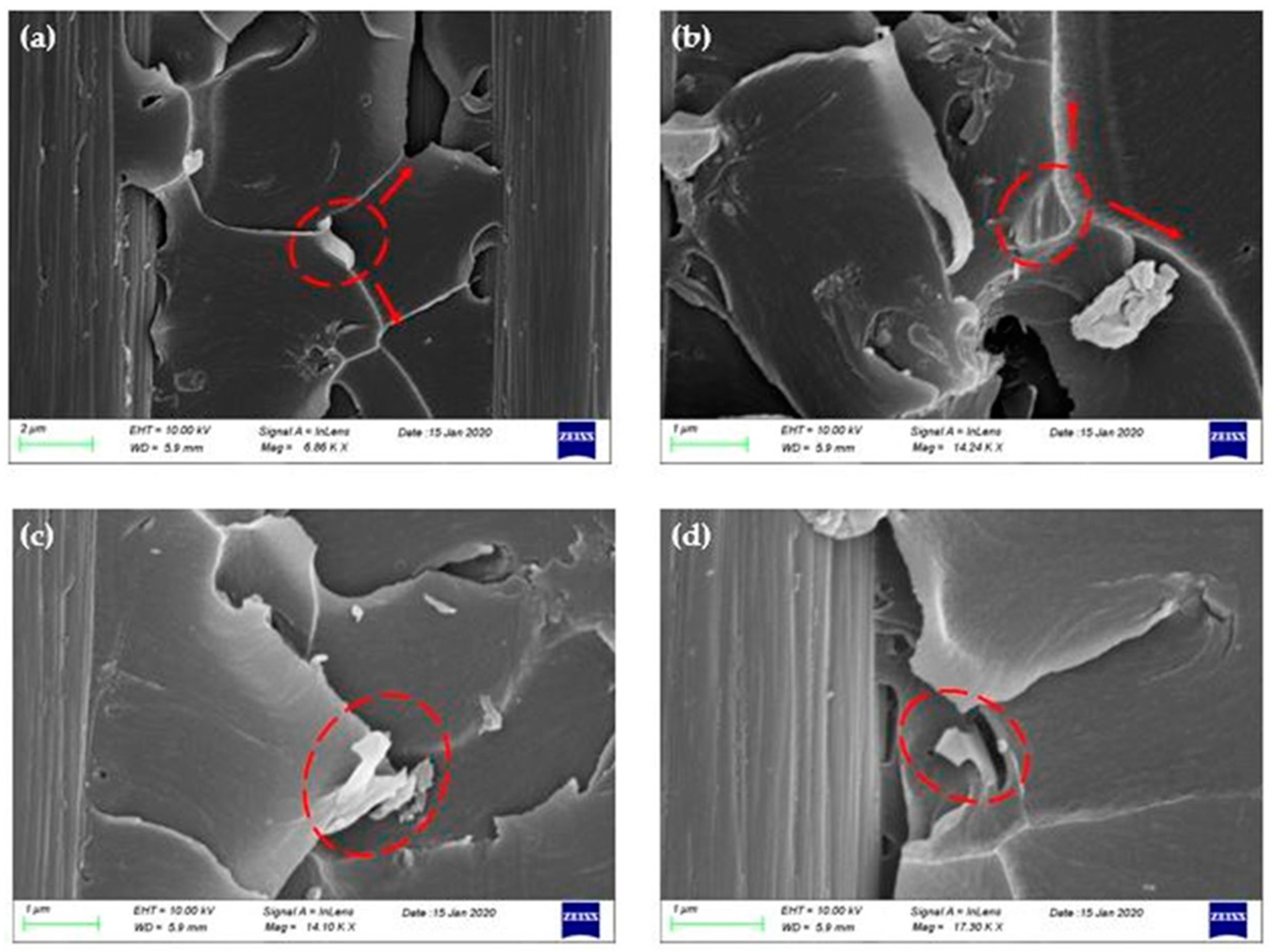
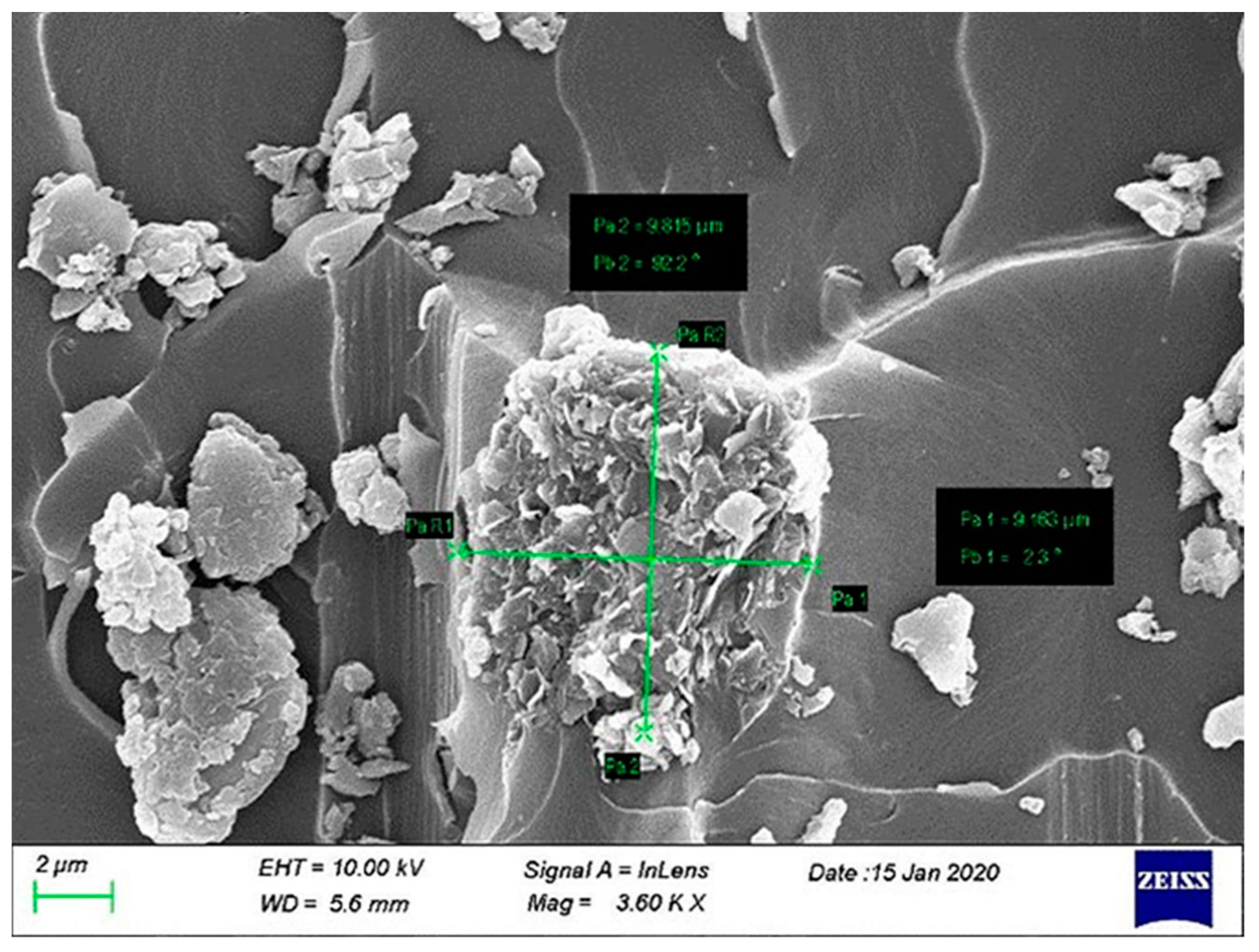
4.3. Fractographic Analysis
4.4. Effect of Specific Surface Area on the Fracture Performance
5. Conclusions
Author Contributions
Funding
Conflicts of Interest
References
- Shtein, M.; Nadiv, R.; Lachman, N.; Daniel Wagner, H.; Regev, O. Fracture behavior of nanotube-polymer composites: Insights on surface roughness and failure mechanism. Compos. Sci. Technol. 2013, 87, 157–163. [Google Scholar] [CrossRef]
- Srivastava, V.; Harris, B. Effect of particles on interlaminar crack growth in cross-plied carbon-fibre/epoxy laminates. J. Mater. Sci. 1994, 29, 548–553. [Google Scholar] [CrossRef]
- Jia, Z.; Feng, X.; Zou, Y. An investigation on mode II fracture toughness enhancement of epoxy adhesive using graphene nanoplatelets. Compos. Part B Eng. 2018, 155, 452–456. [Google Scholar] [CrossRef]
- Tsantzalis, S.; Karapappas, P.; Vavouliotis, A.; Tsotra, P.; Paipetis, A.; Kostopoulos, V.; Friedrich, K. Enhancement of the mechanical performance of an epoxy resin and fiber reinforced epoxy resin composites by the introduction of CNF and PZT particles at the microscale. Compos. Part A Appl. Sci. Manuf. 2007, 38, 1076–1081. [Google Scholar] [CrossRef]
- Hsieh, T.H.; Kinloch, A.J.; Taylor, A.C.; Kinloch, I.A. The effect of carbon nanotubes on the fracture toughness and fatigue performance of a thermosetting epoxy polymer. J. Mater. Sci. 2011, 46, 7525–7535. [Google Scholar] [CrossRef]
- Almuhammadi, K.; Alfano, M.; Yang, Y.; Lubineau, G. Analysis of interlaminar fracture toughness and damage mechanisms in composite laminates reinforced with sprayed multi-walled carbon nanotubes. Mater. Des. 2014, 53, 921–927. [Google Scholar] [CrossRef]
- Vavouliotis, A.; Fiamegou, E.; Karapappas, P.; Psarras, G.; Kostopoulos, V. DC and AC conductivity in epoxy resin/multiwall carbon nanotubes percolative system. Polym. Compos. 2010, 31, 1874–1880. [Google Scholar] [CrossRef]
- Wernik, J.M.; Meguid, S.A. On the mechanical characterization of carbon nanotube reinforced epoxy adhesives. Mater. Des. 2014, 59, 19–32. [Google Scholar] [CrossRef]
- Karapappas, P.; Vavouliotis, A.; Tsotra, P.; Kostopoulos, V.; Paipetis, A. Enhanced Fracture Properties of Carbon Reinforced Composites by the Addition of Multi-Wall Carbon Nanotubes. J. Compos. Mater. 2009, 43, 977–985. [Google Scholar] [CrossRef]
- Li, Y.; Zhang, H.; Huang, Z.; Bilotti, E.; Peijs, T. Graphite Nanoplatelet Modified Epoxy Resin for Carbon Fibre Reinforced Plastics with Enhanced Properties. J. Nanomater. 2017, 2017, 1–10. [Google Scholar] [CrossRef]
- Rafiee, M.; Nitzsche, F.; Laliberte, J.; Thibault, J.; Labrosse, M.R. Simultaneous reinforcement of matrix and fibers for enhancement of mechanical properties of graphene-modified laminated composites. Polym. Compos. 2018, 40, E1732–E1745. [Google Scholar] [CrossRef]
- Adak, N.C.; Chhetri, S.; Murmu, N.C.; Samanta, P.; Kuila, T. Effect of thermally reduced graphene oxide on dynamic mechanical properties of carbon fiber/epoxy composite. In Proceedings of the IOP Conference Series: Materials Science and Engineering, Rourkela, India, 8–9 December 2017; p. 012015. [Google Scholar] [CrossRef]
- Chandrasekaran, S.; Sato, N.; Tölle, F.; Mülhaupt, R.; Fiedler, B.; Schulte, K. Fracture toughness and failure mechanism of graphene based epoxy composites. Compos. Sci. Technol. 2014, 97, 90–99. [Google Scholar] [CrossRef]
- Hashim, U.R.; Jumahat, A. Improved tensile and fracture toughness properties of graphene nanoplatelets filled epoxy polymer via solvent compounding shear milling method. Mater. Res. Express 2018, 6. [Google Scholar] [CrossRef]
- Kang, W.-S.; Rhee, K.Y.; Park, S.-J. Influence of surface energetics of graphene oxide on fracture toughness of epoxy nanocomposites. Compos. Part B Eng. 2017, 114, 175–183. [Google Scholar] [CrossRef]
- Silva, A.A.; Stein, R.; Campos, D.; Indrusiak, T.; Soares, B.G.; Barra, G.M.O. Conducting Materials Based on Epoxy/Graphene Nanoplatelet Composites with Microwave Absorbing Properties: Effect of the Processing Conditions and Ionic Liquid. Front. Mater. 2019, 6. [Google Scholar] [CrossRef]
- Hsieh, T.-H.; Huang, Y.-S.; Shen, M.-Y. Carbon nanotube size effect on the mechanical properties and toughness of nanocomposites. Polym. Compos. 2018, 39, E1072–E1086. [Google Scholar] [CrossRef]
- Zhang, D.D.; Zhao, D.L.; He, B. Effect of Graphene Structure on Mechanical Properties of Graphene/Epoxy Nanocomposites. Adv. Mater. Res. 2013, 873, 496–502. [Google Scholar] [CrossRef]
- Chong, H.M.; Hinder, S.J.; Taylor, A.C. Graphene nanoplatelet-modified epoxy: Effect of aspect ratio and surface functionality on mechanical properties and toughening mechanisms. J. Mater. Sci. 2016, 51, 8764–8790. [Google Scholar] [CrossRef]
- Ravindran, A.R.; Feng, C.; Huang, S.; Wang, Y.; Zhao, Z.; Yang, J. Effects of Graphene Nanoplatelet Size and Surface Area on the AC Electrical Conductivity and Dielectric Constant of Epoxy Nanocomposites. Polymers 2018, 10, 477. [Google Scholar] [CrossRef]
- Wang, G.; Yang, J.; Park, J.; Gou, X.; Wang, B.; Liu, H.; Yao, J. Facile synthesis and characterization of graphene nanosheets. J. Phys. Chem. C 2008, 112, 8192–8195. [Google Scholar] [CrossRef]
- Blake, P.; Brimicombe, P.D.; Nair, R.R.; Booth, T.J.; Jiang, D.; Schedin, F.; Ponomarenko, L.A.; Morozov, S.V.; Gleeson, H.F.; Hill, E.W. Graphene-based liquid crystal device. Nano Lett. 2008, 8, 1704–1708. [Google Scholar] [CrossRef] [PubMed]
- Yang, H.; Shan, C.; Li, F.; Zhang, Q.; Han, D.; Niu, L. Convenient preparation of tunably loaded chemically converted graphene oxide/epoxy resin nanocomposites from graphene oxide sheets through two-phase extraction. J. Mater. Chem. 2009, 19. [Google Scholar] [CrossRef]
- Wang, G.; Shen, X.; Yao, J.; Park, J. Graphene nanosheets for enhanced lithium storage in lithium ion batteries. Carbon 2009, 47, 2049–2053. [Google Scholar] [CrossRef]
- Zaman, I.; Phan, T.T.; Kuan, H.-C.; Meng, Q.; Bao La, L.T.; Luong, L.; Youssf, O.; Ma, J. Epoxy/graphene platelets nanocomposites with two levels of interface strength. Polymer 2011, 52, 1603–1611. [Google Scholar] [CrossRef]
- Paul, D.R.; Robeson, L.M. Polymer nanotechnology: Nanocomposites. Polymer 2008, 49, 3187–3204. [Google Scholar] [CrossRef]
- Leopold, C.; Just, G.; Koch, I.; Schetle, A.; Kosmann, J.B.; Gude, M.; Fiedler, B. Damage mechanisms of tailored few-layer graphene modified CFRP cross-ply laminates. Compos. Part A Appl. Sci. Manuf. 2019, 117, 332–344. [Google Scholar] [CrossRef]
- Srivastava, V.K.; Gries, T.; Veit, D.; Quadflieg, T.; Mohr, B.; Kolloch, M. Effect of nanomaterial on mode I and mode II interlaminar fracture toughness of woven carbon fabric reinforced polymer composites. Eng. Fract. Mech. 2017, 180, 73–86. [Google Scholar] [CrossRef]
- Kostagiannakopoulou, C.; Loutas, T.H.; Sotiriadis, G.; Markou, A.; Kostopoulos, V. On the interlaminar fracture toughness of carbon fiber composites enhanced with graphene nano-species. Compos. Sci. Technol. 2015, 118, 217–225. [Google Scholar] [CrossRef]
- Gojny, F.; Wichmann, M.; Fiedler, B.; Schulte, K. Influence of different carbon nanotubes on the mechanical properties of epoxy matrix composites—A comparative study. Compos. Sci. Technol. 2005, 65, 2300–2313. [Google Scholar] [CrossRef]
- Shokrieh, M.M.; Ghoreishi, S.M.; Esmkhani, M.; Zhao, Z. Effects of graphene nanoplatelets and graphene nanosheets on fracture toughness of epoxy nanocomposites. Fatigue Fract. Eng. Mater. Struct. 2014, 37, 1116–1123. [Google Scholar] [CrossRef]
- Rao, Q.; Huang, H.; Ouyang, Z.; Peng, X. Synergy effects of multi-walled carbon nanotube and graphene nanoplate filled epoxy adhesive on the shear properties of unidirectional composite bonded joints. Polym. Test. 2020, 82. [Google Scholar] [CrossRef]
- Noh, Y.J.; Joh, H.I.; Yu, J.; Hwang, S.H.; Lee, S.; Lee, C.H.; Kim, S.Y.; Youn, J.R. Ultra-high dispersion of graphene in polymer composite via solvent free fabrication and functionalization. Sci. Rep. 2015, 5, 9141. [Google Scholar] [CrossRef] [PubMed]


| Araldite LY 1556 | Aradur 1571 | Accelerator 1573 | Hardener XB 3403 | |
|---|---|---|---|---|
| Component | Epoxy resin | Hardener paste | Accelerator paste | Hardener based on polyamine |
| Aspect (visual) | Clear, pale yellow liquid | White viscous paste | White viscous paste | Clear liquid |
| Viscosity at 25 °C (mPa·s) | 10,000–12,000 | 28,000–40,000 | 60,000–90,000 | 5–20 |
| Density at 25 °C (g/cm3) | 1.15–1.2 | 1.2 | 1.08 | 1 |
| Storage Temperature (°C) | 2–40 | <8 | <8 | 2–40 |
| xGNPs C300 | xGNPs C500 | |
|---|---|---|
| Appearance | Black granules/powder | Black granules/powder |
| Density (g/cm3) | 0.2–0.4 | 0.2–0.4 |
| Specific Surface Area (m2/g) | 300 | 500 |
| Diameter (μm) | <2 | <2 |
| Typical Particle Thickness | Few nanometers | Few nanometers |
| Material | Fiber Volume Fraction |
|---|---|
| Neat | 61% |
| C300 | 58% |
| C500 | 59% |
| Material | Interlaminar Fracture Toughness GIC (kJ/m2) | |
|---|---|---|
| AVG | STDEV | |
| Neat | 0.55 | 0.079 |
| 0.5 wt% C300 | 0.48 | 0.061 |
| 0.5 wt% C500 | 0.69 | 0.084 |
| Material | Interlaminar Fracture Toughness GIIC (kJ/m2) | |
|---|---|---|
| AVG | STDEV | |
| Neat | 1.02 | 0.06 |
| 0.5 wt% C300 | 1.07 | 0.12 |
| 0.5 wt% C500 | 1.36 | 0.16 |
Publisher’s Note: MDPI stays neutral with regard to jurisdictional claims in published maps and institutional affiliations. |
© 2020 by the authors. Licensee MDPI, Basel, Switzerland. This article is an open access article distributed under the terms and conditions of the Creative Commons Attribution (CC BY) license (http://creativecommons.org/licenses/by/4.0/).
Share and Cite
Zafeiropoulou, K.; Kostagiannakopoulou, C.; Sotiriadis, G.; Kostopoulos, V. A Preliminary Study of the Influence of Graphene Nanoplatelet Specific Surface Area on the Interlaminar Fracture Properties of Carbon Fiber/Epoxy Composites. Polymers 2020, 12, 3060. https://doi.org/10.3390/polym12123060
Zafeiropoulou K, Kostagiannakopoulou C, Sotiriadis G, Kostopoulos V. A Preliminary Study of the Influence of Graphene Nanoplatelet Specific Surface Area on the Interlaminar Fracture Properties of Carbon Fiber/Epoxy Composites. Polymers. 2020; 12(12):3060. https://doi.org/10.3390/polym12123060
Chicago/Turabian StyleZafeiropoulou, Konstantina, Christina Kostagiannakopoulou, George Sotiriadis, and Vassilis Kostopoulos. 2020. "A Preliminary Study of the Influence of Graphene Nanoplatelet Specific Surface Area on the Interlaminar Fracture Properties of Carbon Fiber/Epoxy Composites" Polymers 12, no. 12: 3060. https://doi.org/10.3390/polym12123060
APA StyleZafeiropoulou, K., Kostagiannakopoulou, C., Sotiriadis, G., & Kostopoulos, V. (2020). A Preliminary Study of the Influence of Graphene Nanoplatelet Specific Surface Area on the Interlaminar Fracture Properties of Carbon Fiber/Epoxy Composites. Polymers, 12(12), 3060. https://doi.org/10.3390/polym12123060