Figure 1.
Plastic part virtual model P.
Figure 1.
Plastic part virtual model P.
Figure 2.
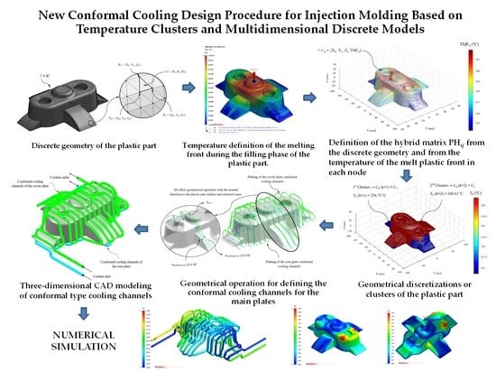
Discrete geometry P’ ∈ ℝ3 of the plastic part and detail of a triangular facet Fi and the nodes Pi1, Pi2, Pi3.
Figure 2.
Discrete geometry P’ ∈ ℝ3 of the plastic part and detail of a triangular facet Fi and the nodes Pi1, Pi2, Pi3.
Figure 3.
Discrete geometry P’ ∈ ℝ3 of the plastic part and detail of the filling injection point and injection mold gate.
Figure 3.
Discrete geometry P’ ∈ ℝ3 of the plastic part and detail of the filling injection point and injection mold gate.
Figure 4.
Detail of the three-dimensional elements and boundary layers that make up the mesh for the Computer Aided Engineering simulation of the filling of the geometry under study P.
Figure 4.
Detail of the three-dimensional elements and boundary layers that make up the mesh for the Computer Aided Engineering simulation of the filling of the geometry under study P.
Figure 5.
Temperature definition of the melting front during the filling phase of the plastic part.
Figure 5.
Temperature definition of the melting front during the filling phase of the plastic part.
Figure 6.
Definition of the hybrid matrix PHij from the discrete geometry P’n ∈ ℝ3 and from the temperature of the melt plastic front TMFij in each node.
Figure 6.
Definition of the hybrid matrix PHij from the discrete geometry P’n ∈ ℝ3 and from the temperature of the melt plastic front TMFij in each node.
Figure 7.
Definition of the geometrical discretizations or clusters of the plastic part.
Figure 7.
Definition of the geometrical discretizations or clusters of the plastic part.
Figure 8.
Definition of Sconformal(i) ∈ ℝ2, nconformal(i) ∈ ℝ2 and Pconformal(i) ∈ ℝ3 for the generation of the layout of the conformal cooling channels.
Figure 8.
Definition of Sconformal(i) ∈ ℝ2, nconformal(i) ∈ ℝ2 and Pconformal(i) ∈ ℝ3 for the generation of the layout of the conformal cooling channels.
Figure 9.
Demoldability analysis of the plastic part discrete geometry.
Figure 9.
Demoldability analysis of the plastic part discrete geometry.
Figure 10.
Definition of nconformal cav ∈ ℝ3 y nconformal cor ∈ ℝ3 for the generation of the pathing of the conformal cooling channels.
Figure 10.
Definition of nconformal cav ∈ ℝ3 y nconformal cor ∈ ℝ3 for the generation of the pathing of the conformal cooling channels.
Figure 11.
2D offset geometrical operation for defining the conformal cooling channels for the main plates of the cavity and core injection mold.
Figure 11.
2D offset geometrical operation for defining the conformal cooling channels for the main plates of the cavity and core injection mold.
Figure 12.
Three-dimensional Computer Aided Design modeling of conformal type cooling channels.
Figure 12.
Three-dimensional Computer Aided Design modeling of conformal type cooling channels.
Figure 13.
Definition domains and boundary conditions of thermal modeling.
Figure 13.
Definition domains and boundary conditions of thermal modeling.
Figure 14.
Plastic part, Case A.
Figure 14.
Plastic part, Case A.
Figure 15.
Cooling system design, Case A. Front view (left) and bottom view (right).
Figure 15.
Cooling system design, Case A. Front view (left) and bottom view (right).
Figure 16.
Temperatures (°C) of the coolant along the conformal cooling system, Case A.
Figure 16.
Temperatures (°C) of the coolant along the conformal cooling system, Case A.
Figure 17.
Pressure (MPa) of the coolant along the cooling system, Case A.
Figure 17.
Pressure (MPa) of the coolant along the cooling system, Case A.
Figure 18.
Average temperature (°C) at the surface of the plastic part after the cooling phase, Case A. Front view (left) and bottom view (right).
Figure 18.
Average temperature (°C) at the surface of the plastic part after the cooling phase, Case A. Front view (left) and bottom view (right).
Figure 19.
Gradient temperature (°C) on the mold surface after the cooling phase, Case A. Front view (left) and bottom view (right).
Figure 19.
Gradient temperature (°C) on the mold surface after the cooling phase, Case A. Front view (left) and bottom view (right).
Figure 20.
Plastic part, Case B.
Figure 20.
Plastic part, Case B.
Figure 21.
Cooling system design, Case B. Front view (left) and bottom view (right).
Figure 21.
Cooling system design, Case B. Front view (left) and bottom view (right).
Figure 22.
Temperature (°C) of the coolant along the conformal cooling system, Case B.
Figure 22.
Temperature (°C) of the coolant along the conformal cooling system, Case B.
Figure 23.
Pressure (MPa) of the coolant along the cooling system, Case B.
Figure 23.
Pressure (MPa) of the coolant along the cooling system, Case B.
Figure 24.
Average temperature (°C) on the surface of the plastic part after the cooling phase, Case B. Front view (left) and bottom view (right).
Figure 24.
Average temperature (°C) on the surface of the plastic part after the cooling phase, Case B. Front view (left) and bottom view (right).
Figure 25.
Gradient temperature (°C) on the mold surface after the cooling phase, Case B. Front view (left) and bottom view (right).
Figure 25.
Gradient temperature (°C) on the mold surface after the cooling phase, Case B. Front view (left) and bottom view (right).
Figure 26.
Plastic part, Case C.
Figure 26.
Plastic part, Case C.
Figure 27.
Cooling system design, Case C. Front view (left) and bottom view (right).
Figure 27.
Cooling system design, Case C. Front view (left) and bottom view (right).
Figure 28.
Temperature (°C) of the coolant along the conformal cooling system, Case C.
Figure 28.
Temperature (°C) of the coolant along the conformal cooling system, Case C.
Figure 29.
Pressure (MPa) of the coolant along the cooling system, Case C.
Figure 29.
Pressure (MPa) of the coolant along the cooling system, Case C.
Figure 30.
Average temperature (°C) on the surface of the plastic part after the cooling phase, Case C. Front view (left) and bottom view (right).
Figure 30.
Average temperature (°C) on the surface of the plastic part after the cooling phase, Case C. Front view (left) and bottom view (right).
Figure 31.
Gradient temperature (°C) on the mold surface after the cooling phase, Case C. Front view (left) and bottom view (right).
Figure 31.
Gradient temperature (°C) on the mold surface after the cooling phase, Case C. Front view (left) and bottom view (right).
Figure 32.
Plastic part, Case D.
Figure 32.
Plastic part, Case D.
Figure 33.
Cooling system design, Case D. Front view (left) and bottom view (right).
Figure 33.
Cooling system design, Case D. Front view (left) and bottom view (right).
Figure 34.
Temperatures (°C) of the coolant along the conformal cooling system, Case D.
Figure 34.
Temperatures (°C) of the coolant along the conformal cooling system, Case D.
Figure 35.
Pressure (MPa) of the coolant along the cooling system, Case D.
Figure 35.
Pressure (MPa) of the coolant along the cooling system, Case D.
Figure 36.
Average temperature (°C) on the surface of the plastic part after the cooling phase, Case D. Front view (left) and bottom view (right).
Figure 36.
Average temperature (°C) on the surface of the plastic part after the cooling phase, Case D. Front view (left) and bottom view (right).
Figure 37.
Gradient temperature field (°C) on the mold surface after the cooling phase, Case D. Front view (left) and bottom view (right).
Figure 37.
Gradient temperature field (°C) on the mold surface after the cooling phase, Case D. Front view (left) and bottom view (right).
Table 1.
Definition of the filling stage technological variables.
Table 1.
Definition of the filling stage technological variables.
| Nomenclature | Units | Description |
|---|
| tfill | s | Filling time of injection mold cavity |
| tpack | s | Packing time of the plastic part |
| tcooling | s | Cooling time of the plastic part |
| Tmelt | °C | Melt plastic flow temperature |
| Tmold | °C | Injection mold temperature |
| Teject | °C | Ejection temperature of the thermoplastic material |
| Pinj | MPa | Maximum filling pressure of the injection machine |
Table 2.
Optimization problem variables.
Table 2.
Optimization problem variables.
| Nomenclature | Units | Description | Notation on the Optimization Problem |
|---|
| Tmold | °C | Mold cavity surface temperature | x (1) |
| Tcoolant | °C | Coolant temperature | x (2) |
| Lconformal | m | Separation distance between conformal cooling channels | x (3) |
| Dconformal | m | Diameter of the conformal cooling channels | x (4) |
| Lp-c | m | Separation distance between the surface of the plastic part and the conformal cooling channels | x (5) … x (11) |
Table 3.
Set-up of the genetic optimization algorithm.
Table 3.
Set-up of the genetic optimization algorithm.
| Genetic Algorithm Options Structure | Defined Set-up | Description |
|---|
| Constraints | Tmold min ≤ x (1) ≤ Tmold max
Tmold min ≤ x (2) ≤ Tmold max
Lmin ≤ x (3) ≤ Lmax
Dmax≤ x (4) ≤ Dmax
Lmin ≤ x (5) … x (11) ≤ Lmax | Constraints restrict the value of the optimization problem variables, allowing the solution to converge on the defined domain. |
| Reproduction | Two Points | Future generations are created from the arithmetic mean of the two random pairs of data of the previous generation population. |
| Mutation | 2% | Definition of the number of individuals of a generation that can be mutated in future generations. |
| Crossover factor | 80% | Definition of the number of individuals that can be crossed in future generations. |
| Migration | Direction: Forward
Migration Interval: 20
Migration factor: 30% | Defines the migration direction of individuals between generations and the individuals fraction that can be migrated between the computational domains. |
Table 4.
Constraint values of the optimization problem variables.
Table 4.
Constraint values of the optimization problem variables.
| Thermoplastic Material | Tmold min (°C) | Tmold max (°C) |
|---|
| Lexan: HF 1110R (PC) | 80.0 | 120.0 |
| Finalloy: EBP-830 (PP) | 15.0 | 75.0 |
| Cycolac: MG47 (ABS) | 49.0 | 71.0 |
| Metallic Material | Lmin (mm) | Lmax (mm) | Dmin(mm) | Dmax (mm) |
| Steel alloy 1.2709 | 3.0 | 20.0 | 3.0 | 6.0 |
Table 5.
Magnitude of the main properties of the materials used in the numerical simulations.
Table 5.
Magnitude of the main properties of the materials used in the numerical simulations.
| Nomenclature | Units | Description | Water (Pure) | Cycolac MG47 (ABS) | Finalloy EBP-830 (PP) | Lexan HF1110R (PC) | Steel Alloy 1.2709 |
|---|
| ρp | kg/m3 | Density | 988.00 | 930.55 | 964.54 | 1060.40 | 8000 |
| Cp | J/kg·°C | Specific heat | 4180 | 2314 | 2350 | 2000 | 450.000 |
| δp, δs | W/m·°C | Thermal conductivity coefficient | 0.643 | 0.184 | 0.300 | 0.260 | 20.000 |
Table 6.
Definition of the filling and cooling stage technological and geometrical variables.
Table 6.
Definition of the filling and cooling stage technological and geometrical variables.
| Nomenclature | Units | Description | Case A-Cycolac MG47 (ABS) | Case B-Lexan HF1110R (PC) | Case C-Finalloy EBP-830 (PP) | Case D-Lexan HF1110R (PC) |
|---|
| tfill | s | Filling time | 1.37 | 1.17 | 2.41 | 2.04 |
| tpack | s | Packing time | 7.02 | 4.25 | 6.53 | 5.49 |
| tcooling | s | Cooling time | 30 | 30 | 30 | 30 |
| Tmelt | °C | Melt temperature | 238 | 285 | 235 | 285 |
| Tmold | °C | Mold temperature | 64.0 | 91.0 | 69.5 | 84.5 |
| Teject | °C | Ejection temperature | 81 | 143 | 110 | 143 |
| Tcoolant | °C | Coolant temperature | 59.3 | 73.6 | 50.0 | 70.0 |
| Pinj | MPa | Maximum injection pressure | 500 | 500 | 500 | 500 |
| Lconformal | mm | Distance between conformal cooling channels | 6.00 | 6.25 | 14.40 | 16.20 |
| Dconformal | mm | Cooling channels diameter | 3.9 | 3.0 | 5.3 | 5.9 |
| Lp-c | mm | Distance between plastic part and cooling channels | 3.75 | 4.50 | 8.35 | 8.90 |
Table 7.
Statistics of meshes defined for each plastic part analyzed numerically.
Table 7.
Statistics of meshes defined for each plastic part analyzed numerically.
| Description | Units | Case A-Cycolac MG47 (ABS) | Case B-Lexan HF1110R (PC) | Case C-Finalloy EBP-830 (PP) | Case D-Lexan HF1110R (PC) |
|---|
| Part mesh node count | - | 158,775 | 369,904 | 273,488 | 164,946 |
| Part mesh element count | - | 382,513 | 885,889 | 593,834 | 352,158 |
| Part mesh volume | m3 | 53.560 × 10⁻⁶ | 33.260 × 10⁻⁶ | 146.610 × 10⁻⁶ | 152.840 × 10⁻⁶ |
| Runner mesh node count | - | 21,449 | 33,818 | 15,004 | 23,618 |
| Runner mesh element count | - | 27,840 | 44,000 | 24,400 | 30,720 |
| Runner mesh volume | m3 | 0.040 × 10⁻⁶ | 0.100 × 10⁻⁶ | 0.060 × 10⁻⁶ | 0.210 × 10⁻⁶ |
| Plastic part precision (ε)–Mesh sizing | mm | 1.5 | 1.0 | 2.0 | 1.5 |
| Element type | | Tetrahedral (10 Nodes) | Tetrahedral (10 Nodes) | Tetrahedral (10 Nodes) | Tetrahedral (10 Nodes) |
| Boundary layers | | Prims (15 Nodes) | Prims (15 Nodes) | Prims (15 Nodes) | Prims (15 Nodes) |
| Offset ratio–Boundary layers | | 0.1 | 0.1 | 0.1 | 0.1 |
Table 8.
Geometry properties of the plastic parts.
Table 8.
Geometry properties of the plastic parts.
| Geometry Properties | Units | Case A | Case B | Case C | Case D |
|---|
| Thickness | mm | 2.5 | 1.5 | 2.0 | 1.5 |
| Volume | mm3 | 53,360 | 33,260 | 146,620 | 152,840 |
| Mold dimension | mm | 200 × 175 × 90 | 240 × 180 × 70 | 375.800 × 200 × 190 | 365.200 × 280 × 170 |
| Mold volume | mm3 | 3,048,100 | 2,958,200 | 14,007,200 | 17,037,100 |
Table 9.
Numerical results obtained for Case A cooling analysis.
Table 9.
Numerical results obtained for Case A cooling analysis.
| Description | Units | Value |
|---|
| Maximum gradient of coolant temperatures | °C | 2.737 |
| Maximum gradient of coolant pressures | MPa | 3.003 |
| Maximum temperature of the part after the cooling phase | °C | 64.839 |
| Minimum part temperature after cooling phase | °C | 59.855 |
| Maximum temperature gradient on the mold surface after the cooling phase | °C | 4.590 |
| Cooling time, analytical solution | s | 11.900 |
| Numerical cooling time, numerical solution | s | 11.529 |
| Relative error in the numerical calculation of the cooling time | % | 3.118 |
Table 10.
Numerical results obtained for Case B cooling analysis.
Table 10.
Numerical results obtained for Case B cooling analysis.
| Description | Units | Value |
|---|
| Maximum gradient of coolant temperatures | °C | 2.192 |
| Maximum gradient of coolant pressures | MPa | 10.030 |
| Maximum temperature of the part after the cooling phase | °C | 86.016 |
| Minimum part temperature after cooling phase | °C | 74.070 |
| Maximum temperature gradient on the mold surface after the cooling phase | °C | 8.109 |
| Cooling time, analytical solution | s | 5.100 |
| Numerical cooling time, numerical solution | s | 5.355 |
| Relative error in the numerical calculation of the cooling time | % | 5.000 |
Table 11.
Numerical results obtained for Case C cooling analysis.
Table 11.
Numerical results obtained for Case C cooling analysis.
| Description | Units | Value |
|---|
| Maximum gradient of coolant temperatures | °C | 6.288 |
| Maximum gradient of coolant pressures | MPa | 0.422 |
| Maximum temperature of the part after the cooling phase | °C | 71.768 |
| Minimum part temperature after cooling phase | °C | 52.572 |
| Maximum temperature gradient on the mold surface after the cooling phase | °C | 9.488 |
| Cooling time, analytical solution | s | 5.100 |
| Numerical cooling time, numerical solution | s | 5.226 |
| Relative error in the numerical calculation of the cooling time | % | 3.255 |
Table 12.
Numerical results obtained for Case D cooling analysis.
Table 12.
Numerical results obtained for Case D cooling analysis.
| Description | Units | Value |
|---|
| Maximum gradient of coolant temperatures | °C | 8.082 |
| Maximum gradient of coolant pressures | MPa | 0.435 |
| Maximum temperature of the part after the cooling phase | °C | 88.633 |
| Minimum part temperature after cooling phase | °C | 74.812 |
| Maximum temperature gradient on the mold surface after the cooling phase | °C | 9.332 |
| Cooling time, analytical solution | s | 4.900 |
| Numerical cooling time, numerical solution | s | 5.085 |
| Relative error in the numerical calculation of the cooling time | % | 3.776 |


 ,
, 


