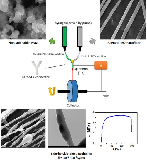
Conductive Bicomponent Fibers Containing Polyaniline Produced via Side-by-Side Electrospinning


Abstract
1. Introduction
2. Materials and Methods
2.1. Materials
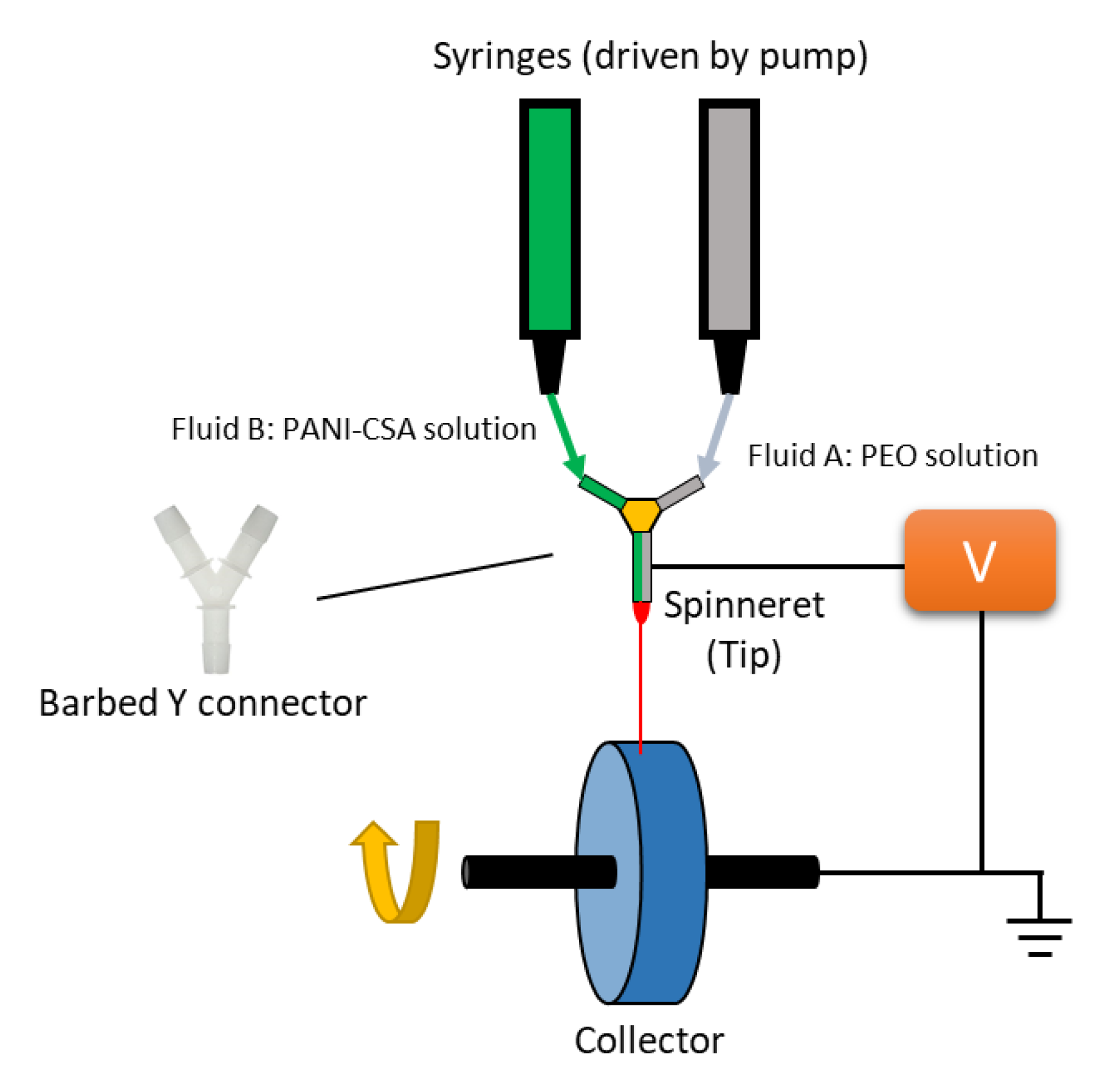
2.2. Preparation of Polymer Solutions and Electrospinning
2.3. Characterization
2.3.1. Fiber Morphology
- Scanning electron microscopy (SEM)
- Transmittance electron microcopy (TEM)
- Energy dispersive X-ray spectroscopy (EDS)
2.3.2. Tensile Test
2.3.3. Electrical Resistance and Conductivity
2.3.4. Thermogravimetric Analysis (TGA)
2.3.5. Viscosity
2.3.6. Fourier-Transform Infrared Spectroscopy (FTIR)
3. Result and Discussion
3.1. Solution Viscosity and Spinnability
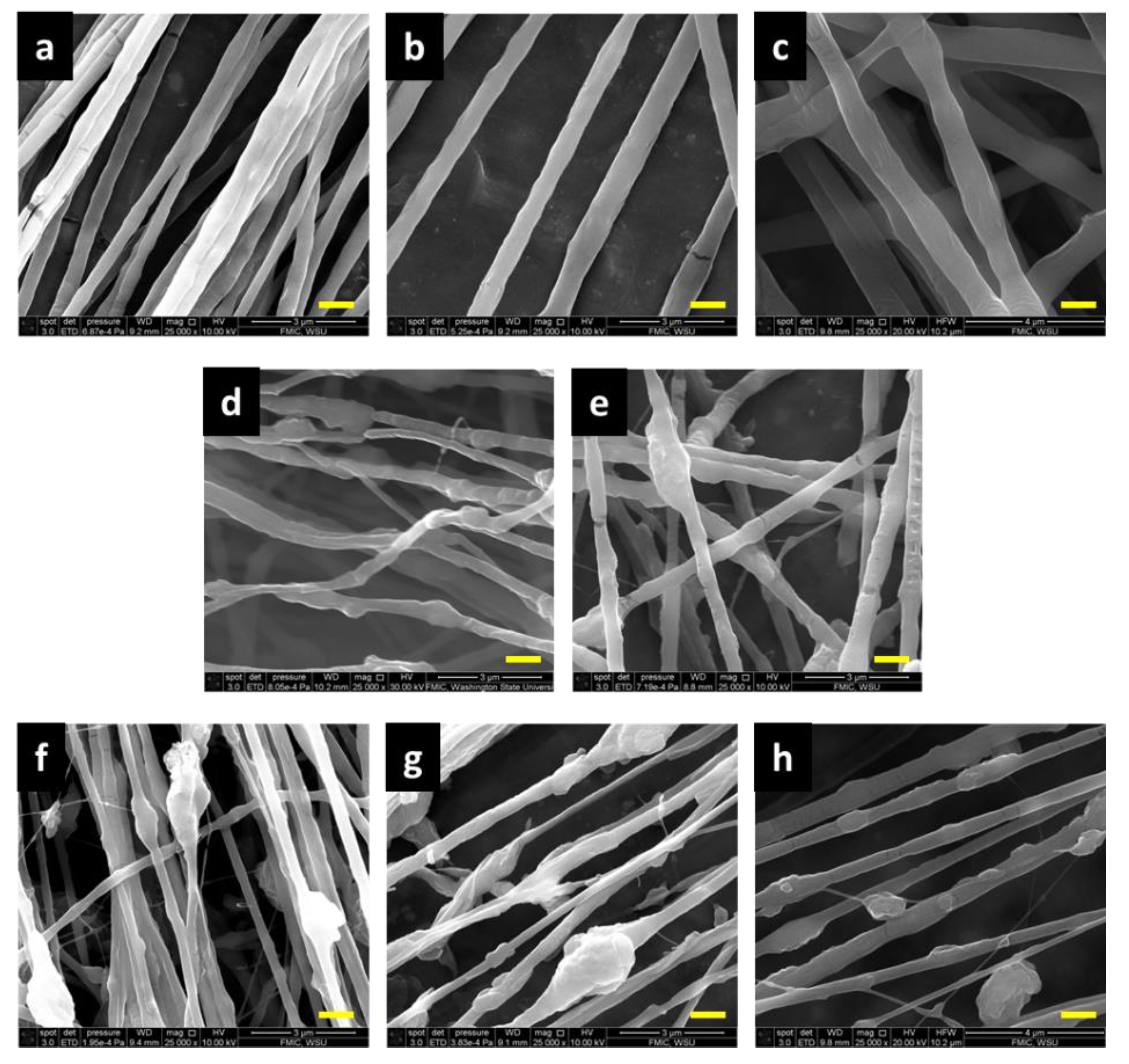
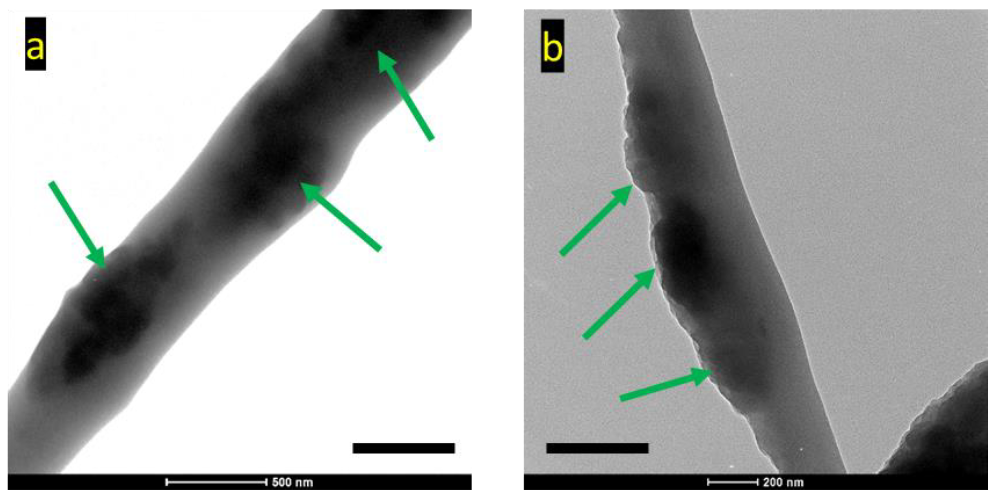
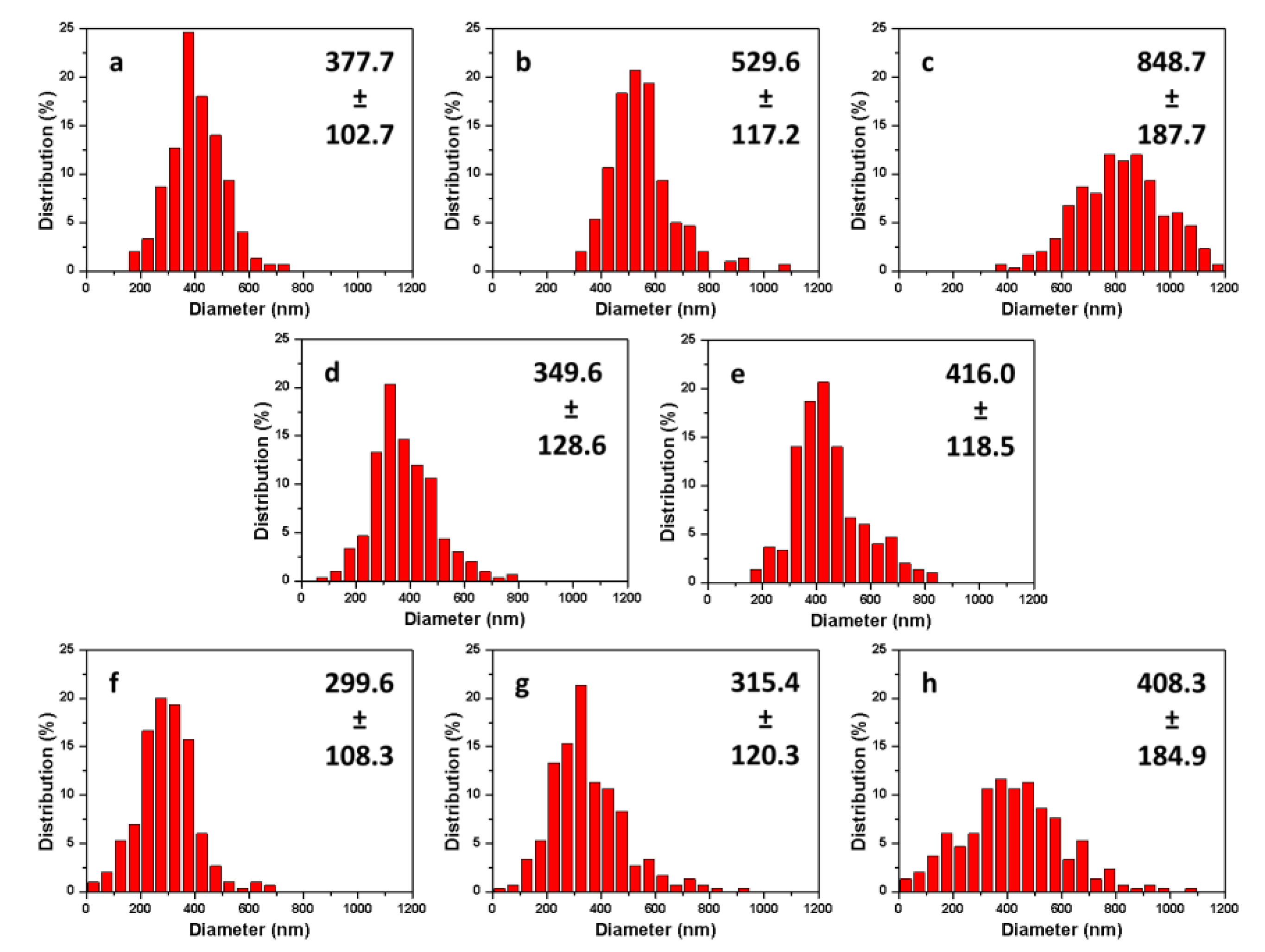
3.2. Morphology Study
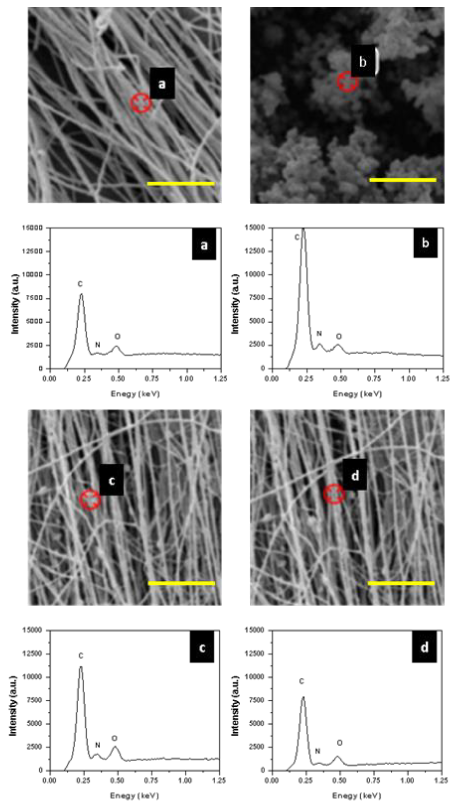
3.3. EDS for Nanofiber Chemical Composition Analysis
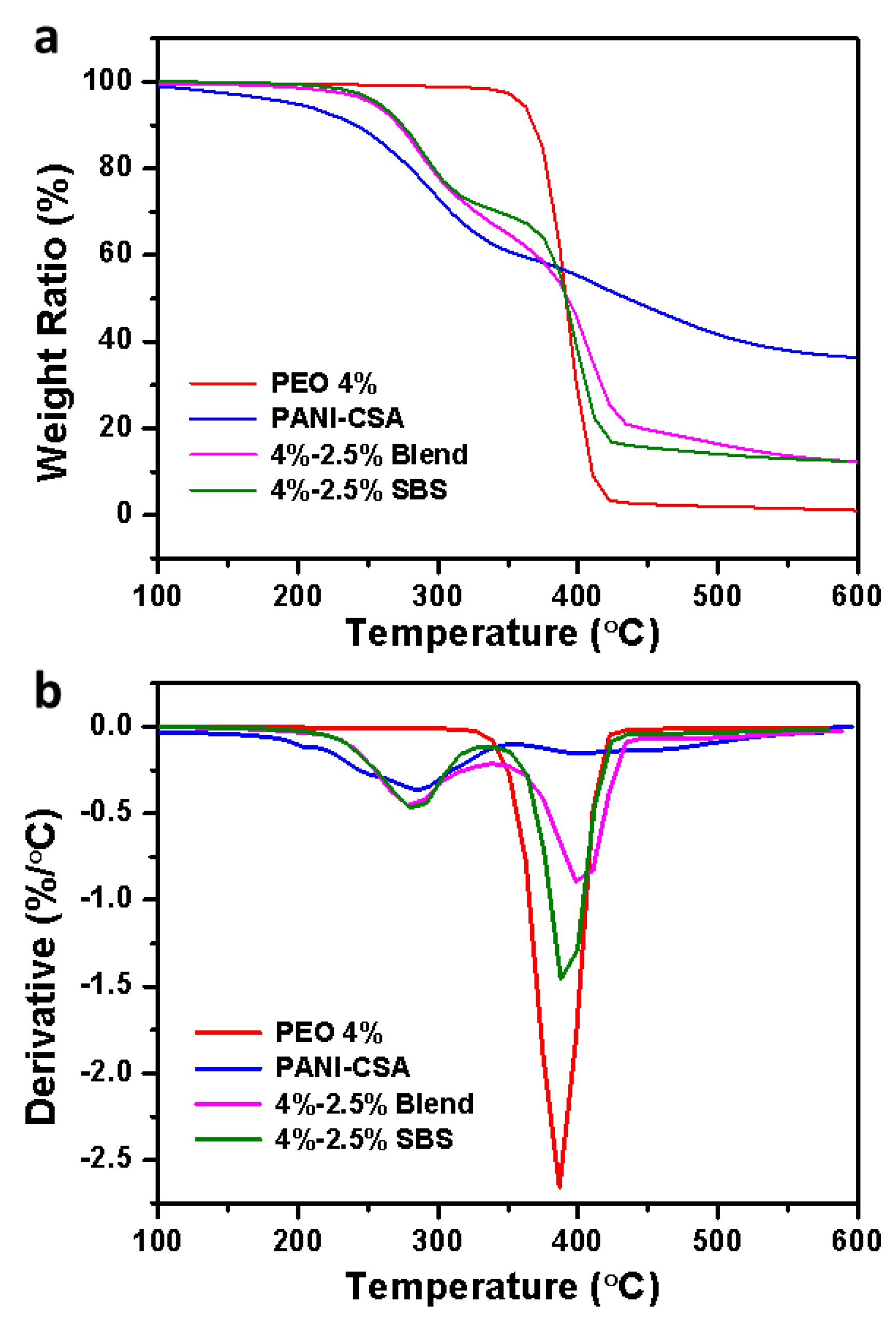
3.4. TGA Analysis
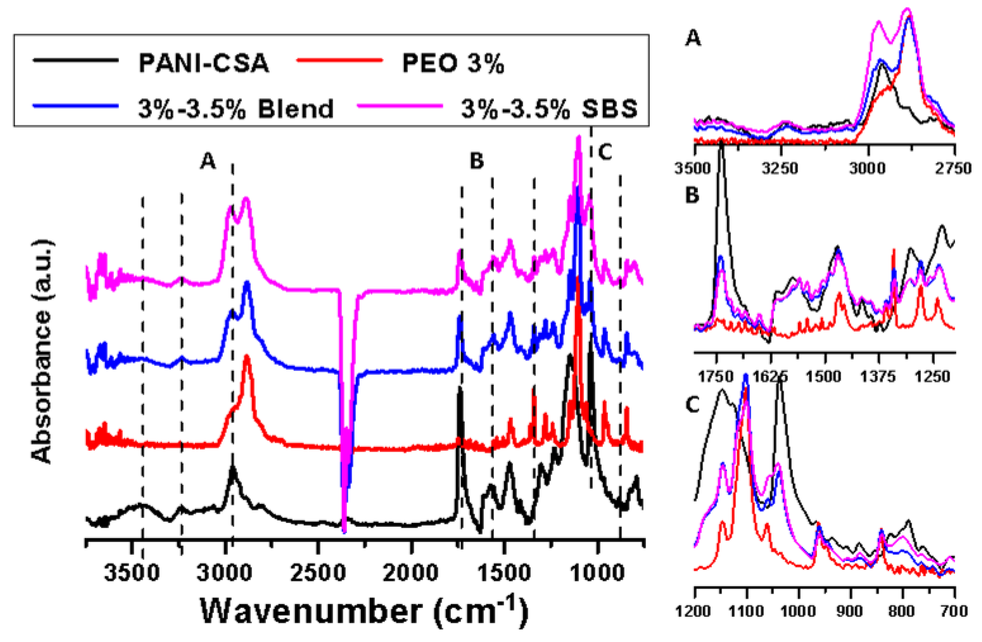
3.5. FTIR Analysis
3.6. Electrical Conductivity
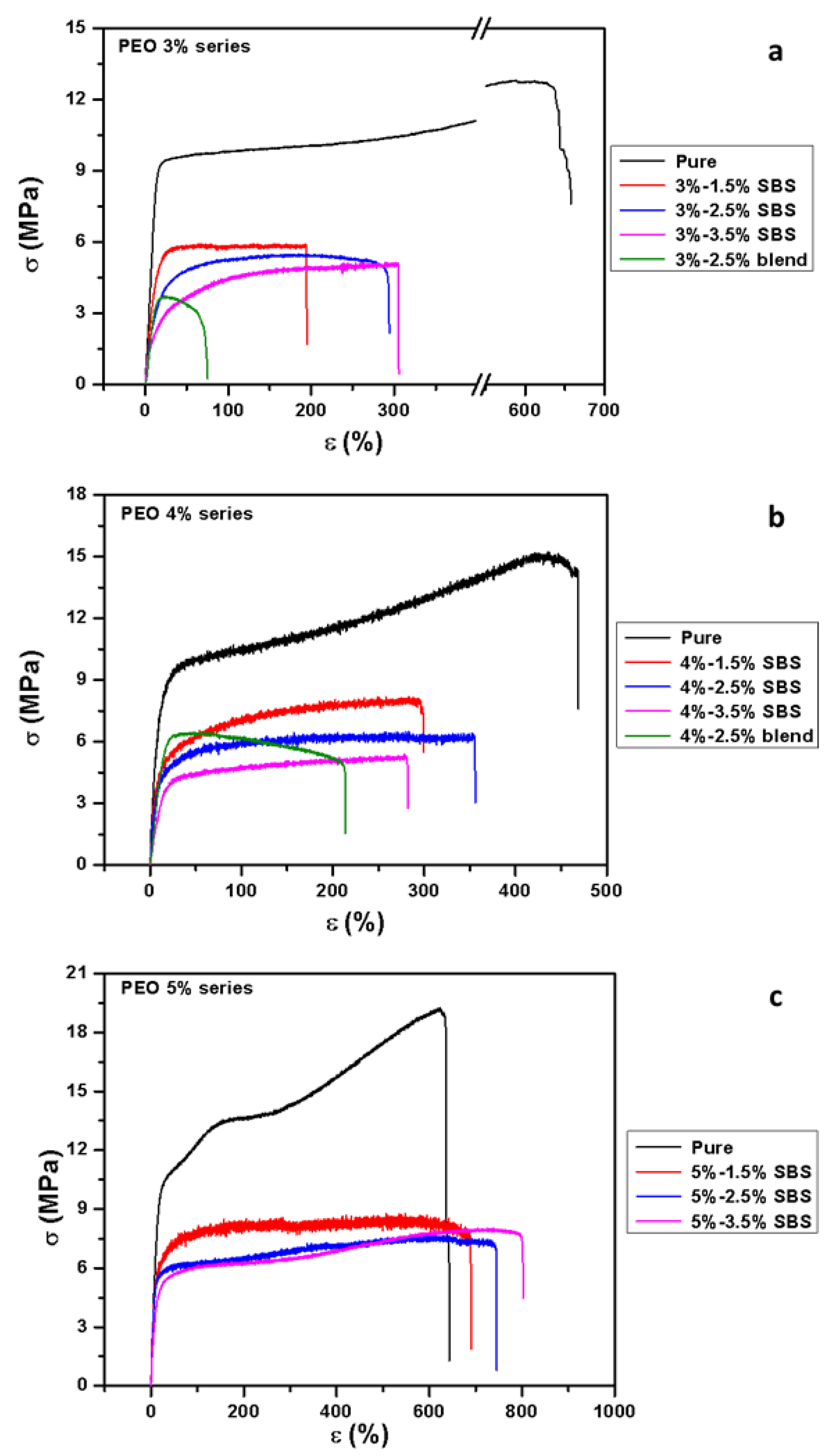
3.7. Tensile Properties
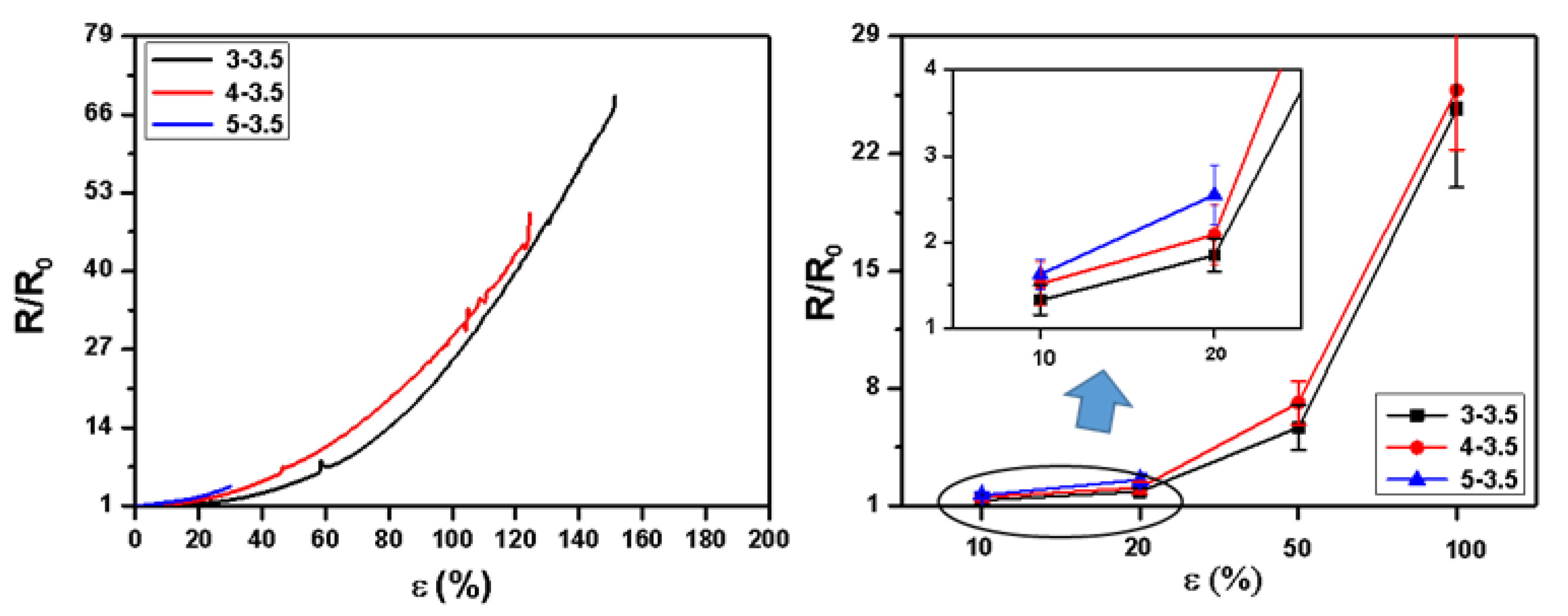
3.8. Relative Resistance during Tensile Stretching
4. Conclusions
Author Contributions
Funding
Acknowledgments
Conflicts of Interest
References
- Lund, A.; van der Velden, N.M.; Persson, N.-K.; Hamedi, M.M.; Müller, C. Electrically conducting fibres for e-textiles: An open playground for conjugated polymers and carbon nanomaterials. Mater. Sci. Eng. R: Rep. 2018, 126, 1–29. [Google Scholar] [CrossRef]
- Research and Markets. Smart textiles and wearable technology: Opportunities for life enhancement and health management. Perform. Appar. Mark. 2011, 1, 25–55. [Google Scholar]
- Castano, L.M.; Flatau, A.B. Smart fabric sensors and e-textile technologies: A review. Smart Mater. Struct. 2014, 23, 053001. [Google Scholar] [CrossRef]
- Zeng, W.; Shu, L.; Li, Q.; Chen, S.; Wang, F.; Tao, X.M. Fiber-based wearable electronics: A review of materials, fabrication, devices, and applications. Adv. Mater. 2014, 26, 5310–5336. [Google Scholar] [CrossRef]
- Mirabedini, A.; Foroughi, J.; Wallace, G.G.J.R.A. Developments in conducting polymer fibres: From established spinning methods toward advanced applications. RSC Adv. 2016, 6, 44687–44716. [Google Scholar] [CrossRef]
- Hong, K.H.; Oh, K.W.; Kang, T.J. Preparation of conducting nylon-6 electrospun fiber webs by the in situ polymerization of polyaniline. J. Appl. Polym. Sci. 2005, 96, 983–991. [Google Scholar] [CrossRef]
- Ćirić-Marjanović, G. Recent advances in polyaniline research: Polymerization mechanisms, structural aspects, properties and applications. Synth. Met. 2013, 177, 1–47. [Google Scholar] [CrossRef]
- Balint, R.; Cassidy, N.J.; Cartmell, S.H. Conductive polymers: Towards a smart biomaterial for tissue engineering. Acta Biomater. 2014, 10, 2341–2353. [Google Scholar] [CrossRef]
- Bhadra, S.; Khastgir, D.; Singha, N.K.; Lee, J.H. Progress in preparation, processing and applications of polyaniline. Prog. Polym. Sci. 2009, 34, 783–810. [Google Scholar] [CrossRef]
- Baker, C.O.; Huang, X.; Nelson, W.; Kaner, R.B. Polyaniline nanofibers: Broadening applications for conducting polymers. Chem. Soc. Rev. 2017, 46, 1510–1525. [Google Scholar] [CrossRef] [PubMed]
- Wessling, B. New insight into organic metal polyaniline morphology and structure. Polymers 2010, 2, 786–798. [Google Scholar] [CrossRef]
- Bertea, A.; Manea, L.; Hristian, L. Associated Polymers, Solvents and Doping Agents to Make Polyaniline Electrospinnable. IOP Conf. Ser.: Mater. Sci. Eng. 2017. [Google Scholar] [CrossRef]
- Wessling, B. Chapter 10—Conductive polymers as organic nanometals. In Handbook of Nanostructured Materials and Nanotechnology; Nalwa, H.S., Ed.; Academic Press: Burlington, NJ, USA, 2000; pp. 501–575. [Google Scholar]
- Dong, H.; Nyame, V.; MacDiarmid, A.G.; Jones, W.E., Jr. Polyaniline/poly (methyl methacrylate) coaxial fibers: The fabrication and effects of the solution properties on the morphology of electrospun core fibers. J. Polym. Sci. Part B: Polym. Phys. 2004, 42, 3934–3942. [Google Scholar] [CrossRef]
- Huang, R.; Long, Y.Z.; Tang, C.C.; Zhang, H.D. Fabrication of nano-branched coaxial polyaniline/polyvinylidene fluoride fibers via electrospinning for strain sensor. Adv. Mater. Res. 2013, 79–82. [Google Scholar] [CrossRef]
- Müller, D.; Mandelli, J.; Marins, J.; Soares, B.; Porto, L.; Rambo, C.; Barra, G. Electrically conducting nanocomposites: Preparation and properties of polyaniline (PAni)-coated bacterial cellulose nanofibers (BC). Cellulose 2012, 19, 1645–1654. [Google Scholar] [CrossRef]
- Merlini, C.; Barra, G.M.d.O.; Ramôa, S.D.A.d.S.; Contri, G.; Almeida, R.d.S.; d’Ávila, M.A.; Soares, B.G. Electrically conductive polyaniline-coated electrospun poly (vinylidene fluoride) mats. Front. Mater. 2015, 2, 14. [Google Scholar] [CrossRef]
- Alcaraz-Espinoza, J.J.; Chávez-Guajardo, A.E.; Medina-Llamas, J.C.; Andrade, C.s.A.; de Melo, C.P. Hierarchical composite polyaniline–(electrospun polystyrene) fibers applied to heavy metal remediation. ACS Appl. Mater. Interfaces 2015, 7, 7231–7240. [Google Scholar] [CrossRef] [PubMed]
- Sarvi, A.; Silva, A.B.; Bretas, R.E.; Sundararaj, U. A new approach for conductive network formation in electrospun poly (vinylidene fluoride) nanofibers. Polym. Int. 2015, 64, 1262–1267. [Google Scholar] [CrossRef]
- Norris, I.D.; Shaker, M.M.; Ko, F.K.; MacDiarmid, A.G. Electrostatic fabrication of ultrafine conducting fibers: Polyaniline/polyethylene oxide blends. Synth. Met. 2000, 114, 109–114. [Google Scholar] [CrossRef]
- Zhou, Y.; Freitag, M.; Hone, J.; Staii, C.; Johnson, A., Jr.; Pinto, N.J.; MacDiarmid, A. Fabrication and electrical characterization of polyaniline-based nanofibers with diameter below 30 nm. Appl. Phys. Lett. 2003, 83, 3800–3802. [Google Scholar] [CrossRef]
- Pinto, N.; Johnson, A., Jr.; MacDiarmid, A.; Mueller, C.; Theofylaktos, N.; Robinson, D.; Miranda, F. Electrospun polyaniline/polyethylene oxide nanofiber field-effect transistor. Appl. Phys. Lett. 2003, 83, 4244–4246. [Google Scholar] [CrossRef]
- Lin, Y.W.; Wu, T.M. Fabrication of water-soluble polyaniline/poly (ethylene oxide)/carbon nanotube electrospun fibers. J. Appl. Polym. Sci. 2012, 126, E123–E129. [Google Scholar] [CrossRef]
- Li, M.; Guo, Y.; Wei, Y.; MacDiarmid, A.G.; Lelkes, P.I. Electrospinning polyaniline-contained gelatin nanofibers for tissue engineering applications. Biomaterials 2006, 27, 2705–2715. [Google Scholar] [CrossRef] [PubMed]
- Jun, I.; Jeong, S.; Shin, H. The stimulation of myoblast differentiation by electrically conductive sub-micron fibers. Biomaterials 2009, 30, 2038–2047. [Google Scholar] [CrossRef]
- McKeon, K.; Lewis, A.; Freeman, J. Electrospun poly (D, L-lactide) and polyaniline scaffold characterization. J. Appl. Polym. Sci. 2010, 115, 1566–1572. [Google Scholar] [CrossRef]
- Jeong, S.I.; Jun, I.D.; Choi, M.J.; Nho, Y.C.; Lee, Y.M.; Shin, H. Development of Electroactive and Elastic Nanofibers that contain Polyaniline and Poly (L-lactide-co-ε-caprolactone) for the Control of Cell Adhesion. Macromol. Biosci. 2008, 8, 627–637. [Google Scholar] [CrossRef]
- Raeesi, F.; Nouri, M.; Haghi, A.K. Electrospinning of polyaniline-polyacrylonitrile blend nanofibers. e-Polymers 2009, 9. [Google Scholar] [CrossRef]
- Wei, M.; Lee, J.; Kang, B.; Mead, J. Preparation of core-sheath nanofibers from conducting polymer blends. Macromol. Rapid Commun. 2005, 26, 1127–1132. [Google Scholar] [CrossRef]
- Hong, K.H.; Kang, T.J. Polyaniline–nylon 6 composite nanowires prepared by emulsion polymerization and electrospinning process. J. Appl. Polym. Sci. 2006, 99, 1277–1286. [Google Scholar] [CrossRef]
- Zhu, Y.; Zhang, J.; Zheng, Y.; Huang, Z.; Feng, L.; Jiang, L. Stable, superhydrophobic, and conductive polyaniline/polystyrene films for corrosive environments. Adv. Funct. Mater. 2006, 16, 568–574. [Google Scholar] [CrossRef]
- Peng, S.; Zhu, P.; Wu, Y.; Mhaisalkar, S.G.; Ramakrishna, S. Electrospun conductive polyaniline–polylactic acid composite nanofibers as counter electrodes for rigid and flexible dye-sensitized solar cells. Rsc Adv. 2012, 2, 652–657. [Google Scholar] [CrossRef]
- Zhang, Y.; Rutledge, G.C. Electrical conductivity of electrospun polyaniline and polyaniline-blend fibers and mats. Macromolecules 2012, 45, 4238–4246. [Google Scholar] [CrossRef]
- Simotwo, S.K.; Kalra, V. Study of co-electrospun nafion and polyaniline nanofibers as potential catalyst support for fuel cell electrodes. Electrochim. Acta 2016, 198, 156–164. [Google Scholar] [CrossRef]
- Kang, T.J.; Kim, D.N.; Hong, K.H. Preparation and properties of polyaniline electrospun fiber web. J. Appl. Polym. Sci. 2012, 124, 4033–4037. [Google Scholar] [CrossRef]
- Merlini, C.; Pegoretti, A.; Araujo, T.M.; Ramoa, S.D.; Schreiner, W.H.; de Oliveira Barra, G.M. Electrospinning of doped and undoped-polyaniline/poly (vinylidene fluoride) blends. Synth. Met. 2016, 213, 34–41. [Google Scholar] [CrossRef]
- Picciani, P.H.; Medeiros, E.S.; Pan, Z.; Orts, W.J.; Mattoso, L.H.; Soares, B.G. Development of conducting polyaniline/poly (lactic acid) nanofibers by electrospinning. J. Appl. Polym. Sci. 2009, 112, 744–753. [Google Scholar] [CrossRef]
- Rahman, N.A.; Gizdavic-Nikolaidis, M.; Ray, S.; Easteal, A.J.; Travas-Sejdic, J. Functional electrospun nanofibres of poly (lactic acid) blends with polyaniline or poly (aniline-co-benzoic acid). Synth. Met. 2010, 160, 2015–2022. [Google Scholar] [CrossRef]
- Castagna, R.; Tunesi, M.; Saglio, B.; Della Pina, C.; Sironi, A.; Albani, D.; Bertarelli, C.; Falletta, E. Ultrathin electrospun PANI nanofibers for neuronal tissue engineering. J. Appl. Polym. Sci. 2016, 133. [Google Scholar] [CrossRef]
- Baştürk, E.; Çakmakçi, E.; Madakbaş, S.; Kahraman, M.V. Surface and proton conductivity properties of electrospun poly (vinyl butyral)/polyaniline nanofibers. Adv. Polym. Technol. 2018, 37, 1774–1781. [Google Scholar] [CrossRef]
- Ucar, N.; Kizildag, N.; Onen, A.; Karacan, I.; Eren, O. Polyacrylonitrile-polyaniline composite nanofiber webs: Effects of solvents, redoping process and dispersion technique. Fibers Polym. 2015, 16, 2223–2236. [Google Scholar] [CrossRef]
- Sarvi, A.; Chimello, V.; Silva, A.; Bretas, R.; Sundararaj, U. Coaxial electrospun nanofibers of poly (vinylidene fluoride)/polyaniline filled with multi-walled carbon nanotubes. Polym. Compos. 2014, 35, 1198–1203. [Google Scholar] [CrossRef]
- Sundaray, B.; Choi, A.; Park, Y.W. Highly conducting electrospun polyaniline-polyethylene oxide nanofibrous membranes filled with single-walled carbon nanotubes. Synth. Met. 2010, 160, 984–988. [Google Scholar] [CrossRef]
- Moayeri, A.; Ajji, A. Fabrication of polyaniline/poly(ethylene oxide)/non-covalently functionalized graphene nanofibers via electrospinning. Synth. Met. 2015, 200, 7–15. [Google Scholar] [CrossRef]
- Simotwo, S.K.; DelRe, C.; Kalra, V. Supercapacitor electrodes based on high-purity electrospun polyaniline and polyaniline–carbon nanotube nanofibers. ACS Appl. Mater. Interfaces 2016, 8, 21261–21269. [Google Scholar] [CrossRef]
- Li, C.; Chartuprayoon, N.; Bosze, W.; Low, K.; Lee, K.H.; Nam, J.; Myung, N.V. Electrospun polyaniline/poly (ethylene oxide) composite nanofibers based gas sensor. Electroanalysis 2014, 26, 711–722. [Google Scholar] [CrossRef]
- Zhou, C.; Chu, R.; Wu, R.; Wu, Q. Electrospun polyethylene oxide/cellulose nanocrystal composite nanofibrous mats with homogeneous and heterogeneous microstructures. Biomacromolecules 2011, 12, 2617–2625. [Google Scholar] [CrossRef]
- Deitzel, J.M.; Kleinmeyer, J.; Harris, D.; Tan, N.B. The effect of processing variables on the morphology of electrospun nanofibers and textiles. Polymer 2001, 42, 261–272. [Google Scholar] [CrossRef]
- Desai, K.; Lee, J.S.; Sung, C. Nanocharacterization of electrospun nanofibers of polyaniline/poly methyl methacrylate blends using SEM, TEM and AFM. Microscopy Microanal. 2004, 10, 556. [Google Scholar] [CrossRef]
- Bhardwaj, N.; Kundu, S.C. Electrospinning: A fascinating fiber fabrication technique. Biotechnol. Adv. 2010, 28, 325–347. [Google Scholar] [CrossRef]
- Picciani, P.H.; Soares, B.G.; Medeiros, E.S.; de Souza, F.G., Jr.; Wood, D.F.; Orts, W.J.; Mattoso, L.H. Electrospinning of Polyaniline/Poly (Lactic Acid) Ultrathin Fibers: Process and Statistical Modeling using a Non-Gaussian Approach. Macromol. Theory Simul. 2009, 18, 528–536. [Google Scholar] [CrossRef]
- Yu, D.-G.; Li, J.-J.; Zhang, M.; Williams, G.R. High-quality Janus nanofibers prepared using three-fluid electrospinning. Chem. Commun. 2017, 53, 4542–4545. [Google Scholar] [CrossRef] [PubMed]
- Chen, G.; Xu, Y.; Yu, D.-G.; Zhang, D.-F.; Chatterton, N.P.; White, K.N. Structure-tunable Janus fibers fabricated using spinnerets with varying port angles. Chem. Commun. 2015, 51, 4623–4626. [Google Scholar] [CrossRef] [PubMed]
- Geng, Y.; Zhang, P.; Wang, Q.; Liu, Y.; Pan, K. Novel PAN/PVP Janus ultrafine fiber membrane and its application for biphasic drug release. J. Mater. Chem. B 2017, 5, 5390–5396. [Google Scholar] [CrossRef]
- Wang, K.; Liu, X.-K.; Chen, X.-H.; Yu, D.-G.; Yang, Y.-Y.; Liu, P. Electrospun hydrophilic Janus nanocomposites for the rapid onset of therapeutic action of helicid. ACS Appl. Mater. Interfaces 2018, 10, 2859–2867. [Google Scholar] [CrossRef] [PubMed]
- Cai, M.; Zhu, J.; Yang, C.; Gao, R.; Shi, C.; Zhao, J.J.P. A parallel bicomponent TPU/PI membrane with mechanical strength enhanced isotropic interfaces used as polymer electrolyte for lithium-ion battery. Polymers 2019, 11, 185. [Google Scholar] [CrossRef] [PubMed]
- Li, W.; Wan, M. Stability of polyaniline synthesized by a doping–dedoping–redoping method. J. Appl. Polym. Sci. 1999, 71, 615–621. [Google Scholar] [CrossRef]
- Miao, Y.-E.; Fan, W.; Chen, D.; Liu, T.J. High-performance supercapacitors based on hollow polyaniline nanofibers by electrospinning. ACS Appl. Mater. Interfaces 2013, 5, 4423–4428. [Google Scholar] [CrossRef]
- Kellenberger, A.; Dmitrieva, E.; Dunsch, L. Structure dependence of charged states in “linear” polyaniline as studied by in situ ATR-FTIR spectroelectrochemistry. J. Phys. Chem. B 2012, 116, 4377–4385. [Google Scholar] [CrossRef] [PubMed]
- Abdulrazzaq, O.; Bourdo, S.E.; Saini, V.; Watanabe, F.; Barnes, B.; Ghosh, A.; Biris, A.S.J.R.A. Tuning the work function of polyaniline via camphorsulfonic acid: An X-ray photoelectron spectroscopy investigation. RSC Adv. 2015, 5, 33–40. [Google Scholar] [CrossRef]
- Osorio-Fuente, J.E.; Gómez-Yáñez, C.; Hernández-Pérez, M.d.l.Á.; Pérez-Moreno, F. Camphor sulfonic acid-hydrochloric acid codoped polyaniline/polyvinyl alcohol composite: Synthesis and characterization. J. Mex. Chem. Soc. 2014, 58, 52–58. [Google Scholar]
- Sim, L.; Gan, S.; Chan, C.H.; Yahya, R.J.S.A.P.A.M.; Spectroscopy, B. ATR-FTIR studies on ion interaction of lithium perchlorate in polyacrylate/poly (ethylene oxide) blends. Spectrochim. Acta Part A: Mol. Biomol. Spectrosc. 2010, 76, 287–292. [Google Scholar] [CrossRef]
- Ojha, S.S.; Stevens, D.R.; Hoffman, T.J.; Stano, K.; Klossner, R.; Scott, M.C.; Krause, W.; Clarke, L.I.; Gorga, R.E.J.B. Fabrication and characterization of electrospun chitosan nanofibers formed via templating with polyethylene oxide. Biomacromolecules 2008, 9, 2523–2529. [Google Scholar] [CrossRef] [PubMed]
- Prabhakaran, M.P.; Ghasemi-Mobarakeh, L.; Jin, G.; Ramakrishna, S. Electrospun conducting polymer nanofibers and electrical stimulation of nerve stem cells. J. Biosci. Bioeng. 2011, 112, 501–507. [Google Scholar] [CrossRef] [PubMed]
- Yang, T.; Wang, W.; Zhang, H.; Li, X.; Shi, J.; He, Y.; Zheng, Q.-s.; Li, Z.; Zhu, H. Tactile sensing system based on arrays of graphene woven microfabrics: Electromechanical behavior and electronic skin application. ACS Nano 2015, 9, 10867–10875. [Google Scholar] [CrossRef] [PubMed]
- Gong, S.; Lai, D.T.; Wang, Y.; Yap, L.W.; Si, K.J.; Shi, Q.; Jason, N.N.; Sridhar, T.; Uddin, H.; Cheng, W. Tattoolike polyaniline microparticle-doped gold nanowire patches as highly durable wearable sensors. ACS Appl. Mater. Interfaces 2015, 7, 19700–19708. [Google Scholar] [CrossRef] [PubMed]
- Liu, W.; Song, M.S.; Kong, B.; Cui, Y. Flexible and stretchable energy storage: Recent advances and future perspectives. Adv. Mater. 2017, 29, 1603436. [Google Scholar] [CrossRef]
- Wang, X.; Dong, L.; Zhang, H.; Yu, R.; Pan, C.; Wang, Z.L. Recent progress in electronic skin. Adv. Sci. 2015, 2, 1500169. [Google Scholar] [CrossRef]


| Viscosity (mPa·s) | PEO Content (w/v %) | ||||
|---|---|---|---|---|---|
| 01 | 32 | 42 | 52 | ||
| PANI-CSA Content (w/v %) | 0 | 1.07 ± 0.01 (solvent) | 555 ± 7 | 1302 ± 26 | 2972 ± 42 |
| 1.5 | 1.24 ± 0.01 | 630 ± 11 | 1585 ± 19 | 3952 ± 29 | |
| 2.5 | 1.33 ± 0.01 | 669 ± 12 | 1712 ± 11 | 4166 ± 21 | |
| 3.5 | 1.44 ± 0.02 | 703 ± 15 | 1894 ± 33 | 4753 ± 32 | |
| PEO-PANI | Blend | Side-by-Side |
|---|---|---|
| 3%–1.5% | 6.8–9.2 × 10⁻⁶ | 5.817.9 × 10−5 |
| 3%–2.5% | 2.5–4.3 × 10⁻⁵ | 1.6–3.8 × 10⁻⁴ |
| 3%–3.5% | 2.8–4.3 × 10⁻⁵ | 3.5–5.8 × 10⁻⁴ |
| 4%–1.5% | 1.4–2.6 × 10⁻⁶ | 2.1–3.7 × 10⁻⁵ |
| 4%–2.5% | 1.3–2.5 × 10⁻⁵ | 0.8–1.5 × 10⁻⁴ |
| 4%–3.5% | 2.1–3.6 × 10⁻⁵ | 2.6–5.2 × 10⁻⁴ |
| 5%–1.5% | Not Spinnable | 1.3–3.2 × 10⁻⁶ |
| 5%–2.5% | 0.9–1.4 × 10⁻⁴ | |
| 5%–3.5% | 1.3–1.9 × 10⁻⁴ |
| Code | Tensile modulus (MPa) | Stress at 10% strain (MPa) | Stress at 20% strain (MPa) | Elongation at break (%) | Maximum strength (MPa) | |
|---|---|---|---|---|---|---|
| PEO 3% | Pure | 63.8 ± 8.5 | 4.9 ± 1.0 | 7.0 ± 0.6 | 618 ± 149 | 14.4 ± 1.5 |
| 3%–1.5% SBS | 49.2 ± 3.0 | 3.7 ± 0.3 | 5.0 ± 0.3 | 202 ± 45 | 5.8 ± 0.3 | |
| 3%–2.5% SBS | 38.6 ± 2.8 | 2.7 ± 0.2 | 3.3 ± 0.5 | 245 ± 79 | 4.9 ± 0.8 | |
| 3%–3.5% SBS | 27.6 ± 6.5 | 2.2 ± 0.4 | 3.2 ± 0.6 | 292 ± 51 | 4.3 ± 0.6 | |
| 3%–2.5% blend | 39.8 ± 6.2 | 2.9 ± 0.2 | 3.7 ± 0.2 | 88 ± 14 | 3.8 ± 0.2 | |
| PEO 4% | Pure | 113.3 ± 13.2 | 6.3 ± 0.4 | 8.0 ± 0.3 | 490 ± 96 | 15.4 ± 1.2 |
| 4%–1.5% SBS | 91.3 ± 6.6 | 4.6 ± 0.2 | 6.5 ± 0.6 | 364 ± 75 | 8.3 ± 0.3 | |
| 4%–2.5% SBS | 71.4 ±4.1 | 3.3 ± 0.3 | 4.2 ± 0.3 | 385 ± 78 | 6.7 ± 0.5 | |
| 4%–3.5% SBS | 51.9 ± 6.9 | 2.7 ± 0.3 | 3.8 ± 0.3 | 305 ± 47 | 5.4 ± 0.4 | |
| 4%–2.5% blend | 58.7 ± 6.2 | 4.2 ± 0.4 | 5.6 ± 0.5 | 201 ± 19 | 6.8 ± 0.3 | |
| PEO 5% | Pure | 121.7 ± 20.8 | 6.7 ± 0.9 | 9.6 ± 0.6 | 604 ± 60 | 17.8 ± 2.5 |
| 5%–1.5% SBS | 86.3 ± 9.2 | 5.3 ± 0.3 | 6.1 ± 0.3 | 751 ± 62 | 8.2 ± 0.4 | |
| 5%12.5% SBS | 78.7 ± 6.8 | 4.2 ± 0.2 | 5.5 ± 0.3 | 692 ± 53 | 7.8 ± 0.2 | |
| 5%–3.5% SBS | 57.2 ± 7.6 | 3.8 ± 0.3 | 4.6 ± 0.4 | 721 ± 117 | 7.9 ± 0.6 | |
| 5%–2.5% blend | Not Spinnable | |||||
© 2019 by the authors. Licensee MDPI, Basel, Switzerland. This article is an open access article distributed under the terms and conditions of the Creative Commons Attribution (CC BY) license (http://creativecommons.org/licenses/by/4.0/).
Share and Cite
Liu, W.; Zhang, J.; Liu, H. Conductive Bicomponent Fibers Containing Polyaniline Produced via Side-by-Side Electrospinning. Polymers 2019, 11, 954. https://doi.org/10.3390/polym11060954
Liu W, Zhang J, Liu H. Conductive Bicomponent Fibers Containing Polyaniline Produced via Side-by-Side Electrospinning. Polymers. 2019; 11(6):954. https://doi.org/10.3390/polym11060954
Chicago/Turabian StyleLiu, Wangcheng, Jinwen Zhang, and Hang Liu. 2019. "Conductive Bicomponent Fibers Containing Polyaniline Produced via Side-by-Side Electrospinning" Polymers 11, no. 6: 954. https://doi.org/10.3390/polym11060954
APA StyleLiu, W., Zhang, J., & Liu, H. (2019). Conductive Bicomponent Fibers Containing Polyaniline Produced via Side-by-Side Electrospinning. Polymers, 11(6), 954. https://doi.org/10.3390/polym11060954