Article

TiO2 NPs Assembled into a Carbon Nanofiber Composite Electrode by a One-Step Electrospinning Process for Supercapacitor Applications

1
Department of Chemistry, Inha University, 100 Inharo, Incheon 22212, Korea
2
Department of Bioenvironmental Chemistry, College of Agriculture & Life Science, Chonbuk National University, Jeonju 561-756, Korea
*
Authors to whom correspondence should be addressed.
Polymers 2019, 11(5), 899; https://doi.org/10.3390/polym11050899
Submission received: 18 April 2019 / Revised: 10 May 2019 / Accepted: 14 May 2019 / Published: 17 May 2019
(This article belongs to the Special Issue Electrospun Nanofibers: Theory and Its Applications)

Abstract

:
In this study, we have synthesized titanium dioxide nanoparticles (TiO2 NPs) into carbon nanofiber (NFs) composites by a simple electrospinning method followed by subsequent thermal treatment. The resulting composite was characterized by state-of-the-art techniques and exploited as the electrode material for supercapacitor applications. The electrochemical behavior of the as-synthesized TiO2 NPs assembled into carbon nanofibers (TiO2-carbon NFs) was investigated and compared with pristine TiO2 NFs. The cyclic voltammetry and charge–discharge analysis of the composite revealed an enhancement in the performance of the composite compared to the bare TiO2 NFs. The as-obtained TiO2-carbon NF composite exhibited a specific capacitance of 106.57 F/g at a current density of 1 A/g and capacitance retention of about 84% after 2000 cycles. The results obtained from this study demonstrate that the prepared nanocomposite could be used as electrode material in a supercapacitor. Furthermore, this work provides an easy scale-up strategy to prepare highly efficient TiO2-carbon composite nanofibers.

Graphical Abstract

1. Introduction

The ever-increasing requirements for clean and sustainable energy have drawn intensive attention to the development of high-performance energy storage systems. Among the various electrochemical energy storage systems, the supercapacitors (SCs) are presumed as one of the most promising candidates for energy storage devices due to their superior performance in terms of power density and specific energy density, higher charge–discharge rate, and long cyclic life as compared to batteries and conventional capacitors [1,2]. Since the performance of the electrode materials governs the performance of the supercapacitor, the recent trend in research on supercapacitors has focused on the fabrication of highly efficient electrode materials with high energy density, which can maintain a high power density and cycling stability [1,3]. The electrodes of most of the supercapacitors are made up of carbon. However, the active electrode surface area and pore size distribution restrict the maximum capacitance [2]. One of the strategies to enhance the performance of electrode materials is to integrate metal oxides into the different carbon-based nanostructures in order to achieve the combined effect of the pseudocapacitance materials with a double-layer capacitor [1,4].
In the past few years, various transition metal oxides such as MnO2, ZnO, NiO, Fe2O3, Co3O4, MgO, and TiO2 (titanium dioxide) have been used along with carbon as a potential electrode material for supercapacitors [1,5]. Recently, TiO2-based nanostructures have been applied in electronic and optoelectronic devices due to their low cost, nontoxicity, eco-friendly nature, and abundant availability [6,7,8]. Due to its good electrochemical activity and high specific energy density, TiO2 can be considered as a promising candidate for a supercapacitor electrode [9,10]. Despite these advantages, the poor conductivity of TiO2 is the main obstacle that restricts its electrochemical performance [11]. Therefore, it is necessary to combine TiO2 with other materials that have good conductivity to form composites. The preparation of a TiO2-carbon composite can be an effective strategy to overcome the limitations of TiO2 to be used in a supercapacitor. In this regard, several TiO2-carbon composite nanostructures based mainly on carbon nanotubes (CNTs) and graphene have been prepared [7,12,13,14,15,16,17]. The composite showed better electrochemical performances; however, the synthesis procedure is complicated, and multiple steps are required. Furthermore, the use of toxic chemicals during the synthesis process also limits their widespread application. For example, the functionalization of CNT is generally carried out by the acid oxidation method using nitric acid (HNO3) and sulfuric acid (H2SO4) [18,19]. Similarly, the reduction of graphene oxide (GO) to reduced graphene oxide (RGO) is accomplished using chemical reducing agents, which may be toxic [20]. Several methods such as microwave, hydrothermal treatment, dip coating, chemical wet-impregnation, and electrospinning have been recognized as strategies for producing a TiO2-carbon composite [21,22,23,24]. Electrospinning has been considered as an effective method for producing good morphology of organic/inorganic nanofibers. However, it is important to find a cheap and eco-friendly procedure in order to synthesize the TiO2-carbon-based nanostructures for a supercapacitor electrode.
Recently, carbon nanofibers via an electrospinning process have gained extensive research interest due to their excellent conductivity, thermal and chemical stability, and easy fabrication process [25,26]. Mostly, carbon nanofibers are prepared from polyacrylonitrile (PAN) polymer. Besides PAN, various precursors, such as polyimide [27], cellulose [28,29,30], polyvinylidene fluoride (PVDF) [31], polyvinyl pyrrolidone (PVP) [32], and polyvinyl acetate (PVA) [33], have also been utilized to prepare carbon fibers via electrospinning followed by a suitable thermal treatment. The carbon fibers are highly applied as the electrode material in a supercapacitor due to their high operating voltage, attractive life span, and high capacity retention [34,35]. However, the specific capacitance and energy density need to be further enhanced in order to meet the growing energy demand. The introduction of metal oxides in the carbon nanofibers is beneficial for boosting the electrochemical properties of the resulting composite by the combined effect of the faradaic capacitance of the metal oxides and the double layer capacitance of the carbon nanofibers [1].
The composite of carbon nanofibers with TiO2 can be prepared easily by adding the modification additives in the precursor solution or TiO2 nanoparticles (NPs) formed earlier in the electrospinning process [1,32]. For example, Wang and coworkers [36] have synthesized TiO2 NP-decorated carbon nanofibers (NFs) from a P25/PAN solution by an electrospinning technique followed first by a heat treatment in air and then in a nitrogen environment. Similarly, Tang et al. [24] synthesized a TiO2-carbon NFs composite via an electrospinning technique by using a titanium oxycompound dispersed PAN/PVP solution. The as-fabricated nanocomposite showed good electrochemical performance [24]. The conversion of carbon fiber from PAN requires stabilization and carbonization processes under oxygen and inert atmosphere, respectively [24,25,37]. In this report, we have synthesized TiO2 NPs assembled into carbon nanofibers by an electrospinning process followed by a thermal treatment directly under an inert atmosphere and then investigated the performance of the as-synthesized nanocomposite in a supercapacitor. Importantly, this procedure simply requires the use of a polymer solution containing a TiO2 precursor. Upon thermal treatment, the prepared nanofibers simultaneously produce TiO2 NPs and carbon resulting in the formation of a TiO2 NP-embedded carbon nanofiber composite. We believe that the synthesis procedure is especially attractive since it offers a promising method for the assembly of TiO2 in carbon fibers and significantly boosts the electrochemical performance of the composite.

2. Experimental

2.1. Materials

Polyvinylpyrrolidone (PVP), acetic acid, and titanium tetraisopropoxide (TTIP, 97%) were purchased from Sigma-Aldrich (Seoul, Korea). Ethanol was purchased from Samchun Pure Chemicals, Co. Ltd., Seoul, Korea. All the chemicals were analytic grade and were used as received.

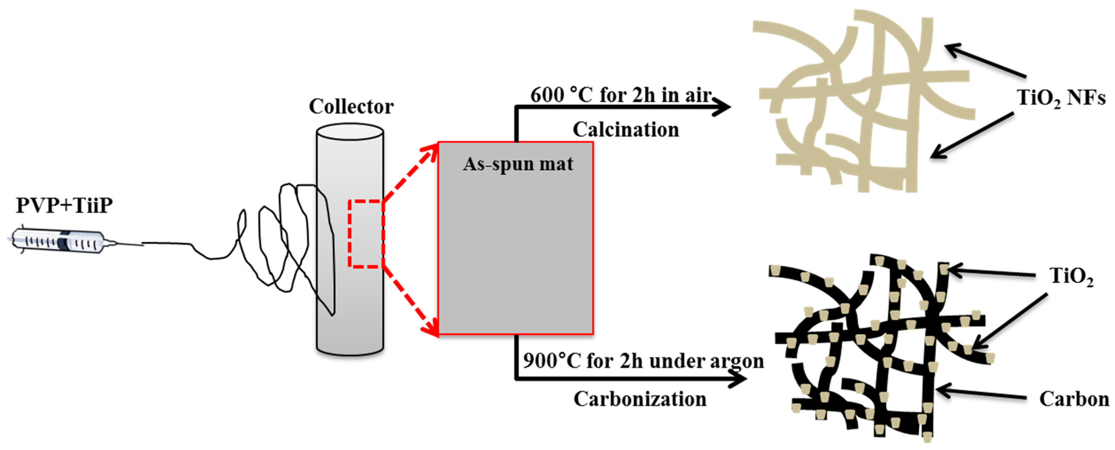
2.2. Synthesis of TiO2 NFs and TiO2-carbon NFs

The synthetic protocol is given in Figure 1. TiO2 nanofibers were synthesized in the laboratory following our previous report [38]. Briefly, in the beginning, 1.5 g of TTIP was taken with 3 g of acetic acid in a vial and stirred for 10 min. Next, 0.5 g of PVP and 4 g of ethanol were added to the above mixture and stirred for 3 h. The solution was electrospun at 20 kV with a 15 cm distance from the tip to the collector. Two nanofiber mats were prepared under identical conditions and vacuum dried at 60 °C for 12 h. The nanofiber mats were subjected to thermal treatment under different conditions (air and argon). After calcination in air at 600 °C for 2 h, the TiO2 nanofibers were obtained. For the synthesis of the TiO2-carbon nanofiber composite, another mat was subjected to carbonization under the argon atmosphere at 900 °C for 2 h.

2.3. Characterization

The morphology of the prepared samples was checked with field-emission scanning electron microscopy (FE-SEM, Hitachi S-7400, Tokyo, Japan) and transmission electron microscopy (TEM, JEOL Ltd., Tokyo, Japan). The lattice structures were studied by X-ray diffractometer with Cu Kα radiation (λ = 0.15496 nm, Rigaku Co., Tokyo, Japan), scanned from 10 to 80°. The samples were characterized with Raman spectra by collecting on a Fourier transform infrared-Raman spectrometer (RFS-100S, Bruker, Hamburg, Germany). The Fourier transform infrared (FTIR) spectra were recorded using an ABB Bomen MB100 Spectrometer (Bomen, QC, Canada). The thermal behavior was studied by thermogravimetric analysis (TGA, Perkin-Elmer, Akron, OH, USA). For the TGA test, the samples were kept in a platinum pan located inside the furnace and heated from 25 to 800 °C under air flow at a heating rate of 10 °C/min.

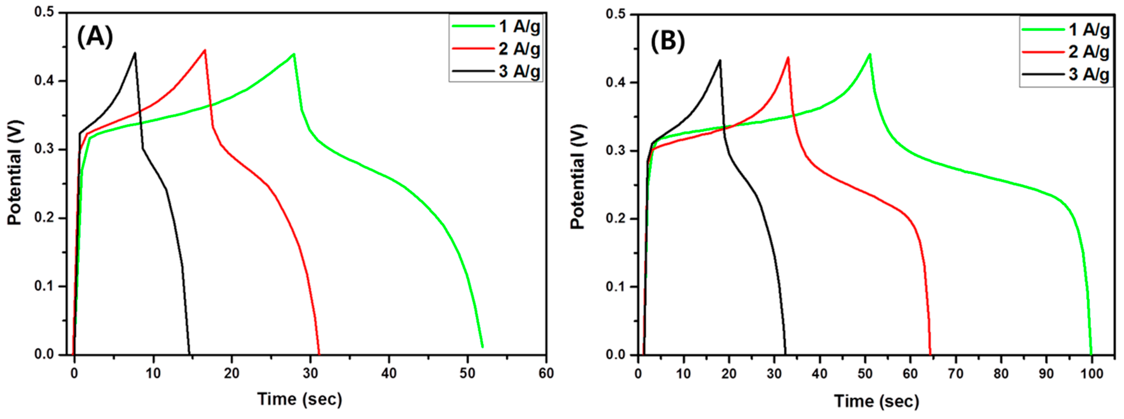
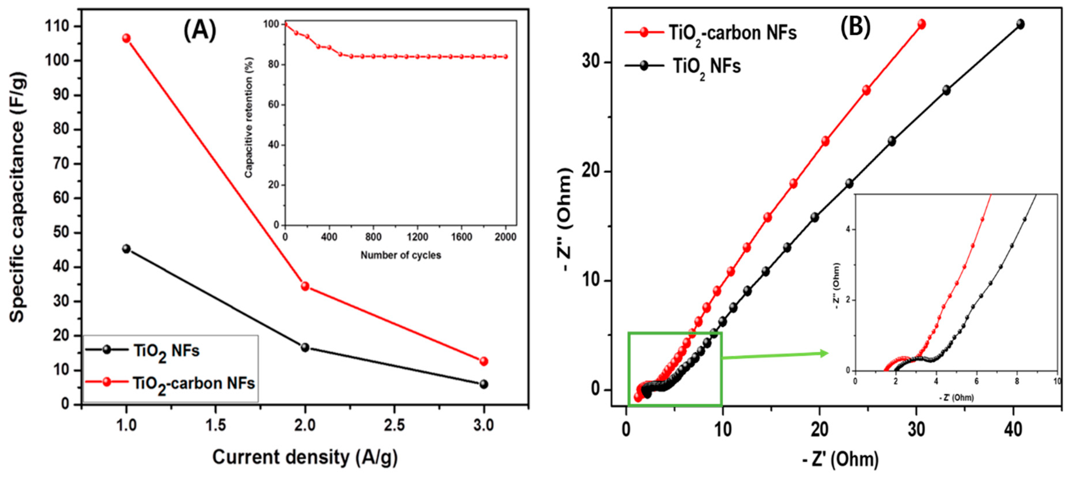
2.4. Electrochemical Studies

The working electrodes were prepared by coating the nickel foam with a homogenous slurry of as-prepared samples, carbon black, and polyvinylidene fluoride (PVDF) at a weight ratio of 8:1:1 in N-methyl-2-pyrrolidone (NMP). The substrate was then dried at 60 °C for 12 h. The morphology of the as-prepared slurry is given in Figure 2, which shows that the nanofibers were well distributed in the slurry. The electrochemical performance was investigated with a conventional three-electrode electrochemical analyzer at room temperature in a 2 M KOH solution as an electrolyte. Nickel foam, Ag/AgCl, and Pt wire were used as the working reference and counter electrodes, respectively. Cyclic voltammetry (CV), galvanostatic charge–discharge (GCD), electrochemical impedance spectroscopy (EIS), and the stability by charge–discharge cycles were performed using Iviumstat.

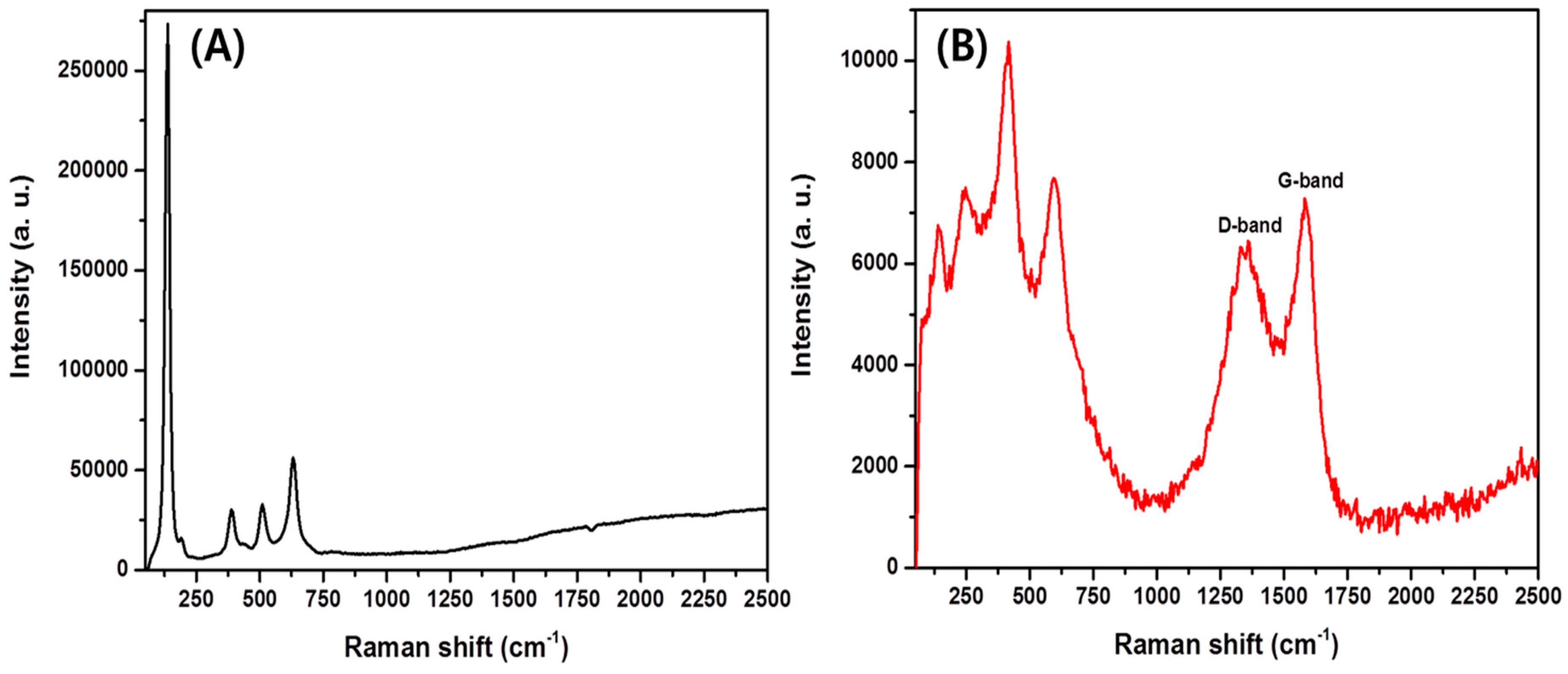
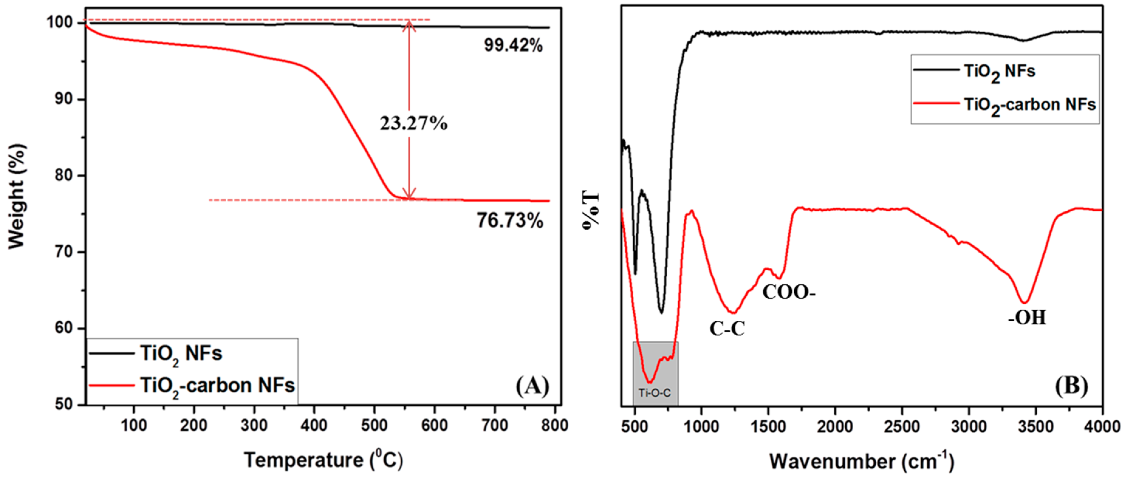
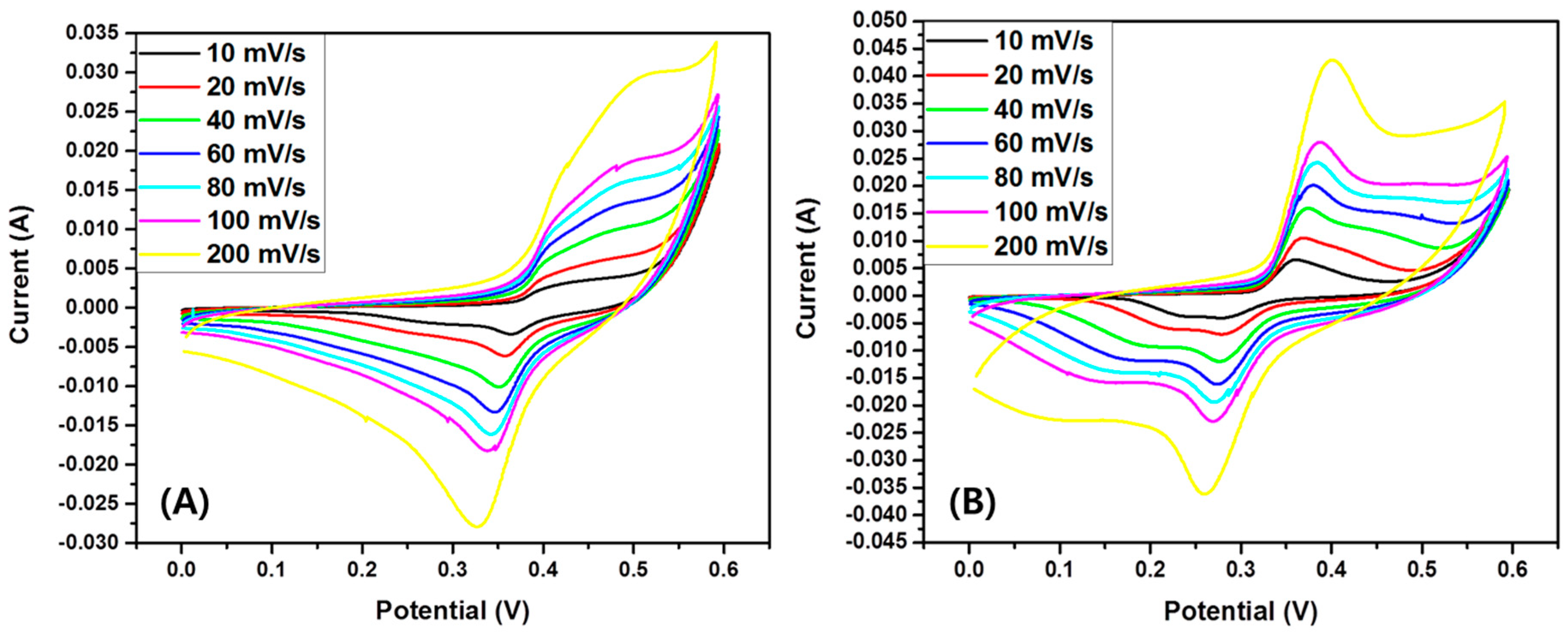
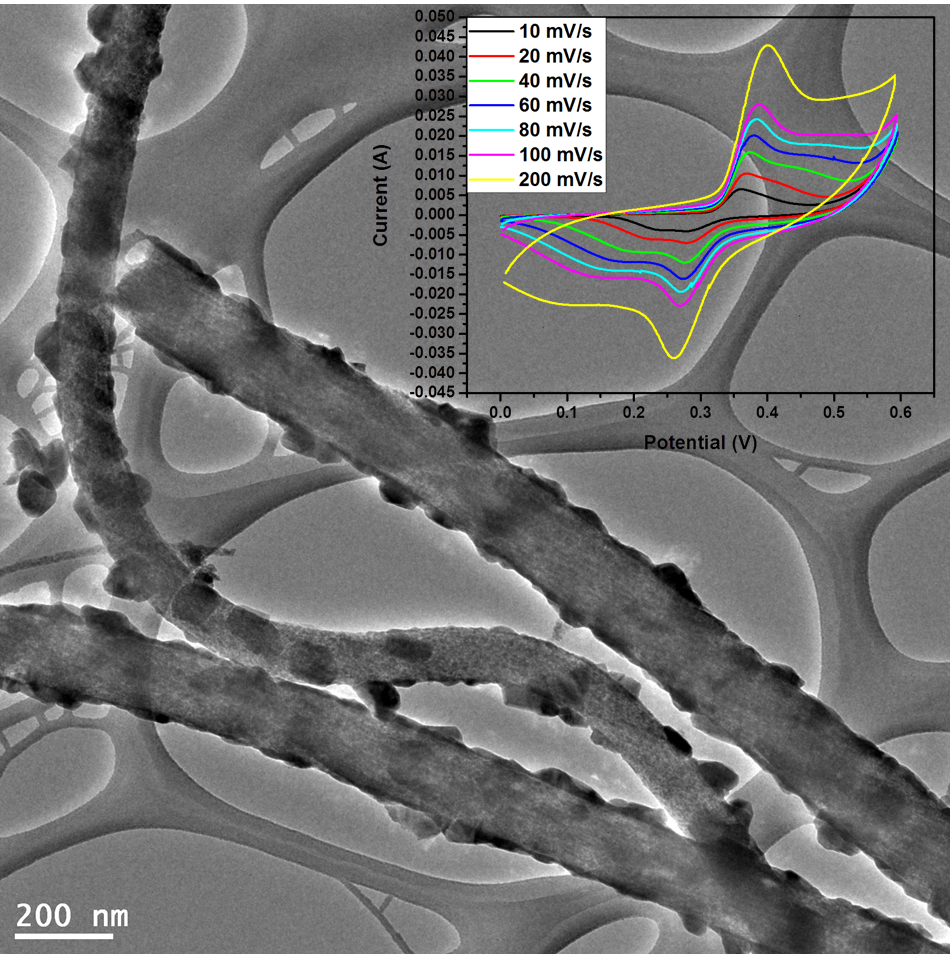
3. Results and Discussion

Figure 3 shows the XRD patterns of the nanofibers synthesized under different calcination conditions. The nanofibers were found to be crystalline in both cases. As in the figure, the TiO2 nanofibers obtained by calcination at 600 °C in an air atmosphere possessed both anatase and rutile phases [32]. On the other hand, the TiO2-carbon composite fibers obtained by carbonization at 900 °C under an argon atmosphere consisted mainly of the rutile phase [32]. It is noteworthy to mention that the higher calcination temperature motivated the transformation of the crystal phase from anatase to rutile [39]. Furthermore, a broad peak located between the 2 theta values of 22° and 26° was observed, which is attributed to the (002) plane of the amorphous carbon [1]. Thus, the XRD suggests a successful conversion of PVP to carbon under the inert atmosphere. The crystal size of the as-synthesized TiO2 and TiO2-carbon composite fibers were calculated by employing the Debye–Scherrer equation with respect to their highly intensified peaks as below:
D = k λ ( β cos θ ) ,
where “D” is the size of the crystal, “k” is a Scherer’s constant, “λ” is the wavelength of the X-ray, “β” is the full width at half maximum (FWHM) of the main peak, and “θ” is the diffraction angle. From the calculation, the obtained crystal sizes for TiO2 NFs and TiO2-carbon NFs were 25.11 and 27.48 nm, respectively.
Figure 4A–C depict the morphologies of the as-spun fiber membrane, TiO2 NFs, and TiO2-carbon NFs, respectively. The as-spun nanofibers showed continuous and bead-free morphology with an average fiber diameter of 290 ± 130 nm (Figure 4A). Well-preserved nanofibrous morphology was obtained after the thermal treatment in both cases. TiO2 nanofibers showed smooth and continuous morphology. It is noticeable that during the calcination process, the PVP was selectively removed and continuous fibers of TiO2 were obtained (Figure 4B). The calcination under the inert atmosphere resulted in the formation of TiO2-incorporated carbon nanofiber structure. During the calcination under the inert atmosphere, PVP was graphitized and titanium tetraisopropoxide was decomposed to a stable TiO2 form, leading to the production of TiO2-carbon composite fibers (Figure 4C). TiO2 NFs showed an average fiber diameter of 250 ± 170 nm, while the TiO2-carbon NFs showed an average diameter of 160 ± 115 nm. The difference in diameter distribution is attributed to the atmospheric condition during the thermal treatment. The internal structure of the as-prepared samples was studied by transmission electron microscopy (TEM). As in the figure, the pure TiO2 NFs revealed a smooth and uniform fibrous morphology (Figure 5A), whereas the composite nanofibers were comprised of carbon nanofibers embedded with TiO2 nanocrystals (Figure 5B). The existence of carbon nanofibers and TiO2 in the composite was also confirmed by the mapping images (Figure 5C).
Figure 6 shows the Raman spectra of pristine TiO2 NFs and TiO2-CNFs. As in Figure 6A, the pristine TiO2 NFs are rich in the anatase phase showing major peaks at 142, 388, 516, and 638 cm−1 [36,40,41]. After calcination under argon atmosphere at 900 °C (Figure 6B), the major anatase peak at 142 was highly suppressed and other peaks disappeared. Instead, three new peaks appeared at about 245, 420, and 600 cm−1, which were ascribed to the rutile phase of TiO2 [36,40]. These changes indicate a transformation of the anatase to rutile phase upon a higher degree of thermal treatment. Besides the TiO2 peaks, two broad peaks corresponding to the D-band and G-band of carbon were observed around 1350 and 1590 cm−1, respectively, which further proves that the PVP had been converted to the carbon structure [25]. The results obtained from Raman are consistent with the XRD data.
Figure 7A represents the thermogravimetric analysis (TGA) profiles of the samples. The pristine TiO2 NFs show high thermal stability (~99.42% at 800 °C). In the case of the composite sample, a gradual decrease in the weight was observed until 550 °C and after that temperature, there was no weight loss. Since TiO2 did not decompose at the given temperature, the weight loss (23.27%) could be attributed to the loss of the carbon content in the composite sample. From the obtained data, the carbon and TiO2 contents in the composite sample were estimated to be ~23.27% and ~76.73%, respectively. The interaction between the TiO2 and carbon was studied by Fourier transform infrared spectroscopy (FTIR) and the results are given in Figure 7B. The pristine TiO2 NFs showed absorption peaks around 500–700 and 3400 cm−1 for Ti–O vibration and O–H bending of water molecules absorbed, respectively [42]. In the case of TiO2-carbon composite nanofibers, the peaks at about 1200 and 1550 cm−1 are attributed to the C–C stretching vibration and asymmetric and symmetric stretching band of COO–, respectively [1]. The presence of Ti–O–C bonds around 500–750 cm−1 represents the interaction of TiO2 with the carbon, suggesting the successful formation of the composite [6,23].
The electrochemical performance of the as-synthesized TiO2-carbon NFs compared with the pristine TiO2 NFs was evaluated by CV, GCD, and EIS tests in a three-electrode system electrochemical cell by using 2 M KOH as an electrolyte. Figure 8A,B show the CV curves of pristine TiO2 and TiO2-carbon NF samples at different scan rates from 10 to 200 mV/s with a potential window from 0 to 0.6 V, respectively. As in the figure, the CV curve of TiO2-carbon NFs shows a larger area compared to that of pristine TiO2 NFs, suggesting a better capacitive behavior. The quasi-rectangular shape of all curves clearly indicates pseudocapacitive characteristics. The slight difference in the redox peaks of the composite compared to the pristine TiO2 NFs may be due to the structural difference in the two samples. It is noteworthy to mention that the pristine TiO2 NFs were composed of both rutile and anatase phases, whereas the TiO2-carbon NFs were composed mainly of the rutile phase. In addition, the TiO2-carbon sample could have the combined effect of the faradaic capacitance of the TiO2 and the double-layer capacitance of the carbon.
The specific capacitance of the composite material was quantified by GCD studies over the potential window between 0 and 0.45 V at various current densities (1, 2, and 3 A/g) as shown in Figure 9. It can be seen that when the current density was increased, the discharge time of the material decreased significantly. This could be due to the sluggish kinetics of the redox reaction to fast potential change [5]. Many factors such as specific surface area, pore size, and conductivity can affect the specific capacitance of the electrode materials [43]. The specific capacitance of the electrodes was calculated by the equation below:
C = I ·   Δ t m ·   Δ V   ,
where “C” is the specific capacitance (F/g), “I” is the charge–discharge current (A), “t” is the discharge time (s), “m” is the mass of the active material (g), and “V” is the potential window (V). The potential window in the charge–discharge curves match with the cyclic voltammetry curves and suggest that the specific capacitance of the materials is due mostly to the faradaic reaction [1]. The specific capacitances of TiO2 NFs were 45.31, 16.62, and 5.92 F/g at the current densities of 1, 2, and 3 A/g, respectively (Figure 10A). As expected, the specific capacitance values were found to be increased in the case of TiO2-carbon NFs. The specific capacitance of the TiO2-carbon NF composite was calculated to be 106.57, 34.44, and 12.59 F/g at the current densities of 1, 2, and 3 A/g, respectively (Figure 10A). It is obvious that the capacitance of the electrode decreased with increasing current densities, which was due to the kinetic resistance and insufficient charge transfer across the electrode–electrolyte interface at higher current densities [5,43]. A drop in the discharge curve in the case of pristine TiO2 NFs was noticed, which could be due to the equivalent series resistance (ESR). As compared to the pristine TiO2 NFs, the composite showed better performance. The electron-transfer kinetics of the electrode materials were studied by EIS analysis (Figure 10B). The smaller semicircular arc in the high-frequency range in the Nyquist plots of the TiO2-carbon NF composite as compared to the pristine TiO2 NFs (inset in Figure 10B) shows a better charge transfer property than that of the pristine TiO2 NFs [1,44]. The inset in Figure 10A displays cyclic stability of the TiO2-carbon NF composite. As in the figure, it revealed about 84% capacitance retention after 2000 cycles (Figure 10A; inset). A comparison of the electrochemical performance of the as-synthesized TiO2-carbon composite nanofibers with some previously investigated electrodes is given in Table 1, which indicates a satisfactory performance of the as-prepared TiO2-carbon NF composite for supercapacitor applications.

4. Conclusions

TiO2 NPs embedded into carbon nanofibers were successfully prepared by an electrospinning technique and post thermal treatment under argon atmosphere. Upon heating at 900 °C, the anatase to rutile phase transformation was achieved. The loading of TiO2 into the amorphous carbon showed an extraordinary enhancement in terms of electrochemical properties. The cyclic voltammetry, galvanostatic charge–discharge, and EIS test results exhibited a combined synergistic effect of TiO2 and carbon fibers. Furthermore, the higher conductivity of the rutile phase and lower charge limitation also favored the electrochemical property enhancement. Overall, the results obtained from the electrochemical study and the easy synthesis protocol show potential application in several applications, including supercapacitors.

Author Contributions

Conceptualization, S.-J.P.; methodology, B.P.; software, B.P.; validation, M.P. and S.-J.P.; formal analysis, B.P.; investigation, S.-J.P.; resources, M.P. and S.-J.P.; data curation, B.P.; writing—original draft preparation, B.P.; writing—review and editing, S.-J.P.; visualization, B.P.; supervision, S.-J.P.; project administration, S.-J.P.; funding acquisition, M.P. and S.-J.P.

Funding

This research was supported by the Korea Evaluation institute of Industrial Technology (KEIT) through the Carbon Cluster Construction project (10083586, Development of petroleum based graphite fibers with ultra-high thermal conductivity) funded by the Ministry of Trade, Industry and Energy (MOTIE, Korea). This study was also supported by the National Research Foundation of Korea (NRF) grant funded by the Korea government (MSIT) (No. NRF-2019R1A2C1004467).

Conflicts of Interest

The authors declare no conflict of interest.

References

  1. Pant, B.; Park, M.; Ojha, G.P.; Park, J.; Kuk, Y.-S.; Lee, E.-J.; Kim, H.-Y.; Park, S.-J. Carbon nanofibers wrapped with zinc oxide nano-flakes as promising electrode material for supercapacitors. J. Colloid Interface Sci. 2018, 522, 40–47. [Google Scholar] [CrossRef] [PubMed]
  2. Elmouwahidi, A.; Bailón-García, E.; Castelo-Quibén, J.; Pérez-Cadenas, A.F.; Maldonado-Hódar, F.J.; Carrasco-Marín, F. Carbon–TiO2 composites as high-performance supercapacitor electrodes: synergistic effect between carbon and metal oxide phases. J. Mater. Chem. A 2018, 6, 633–644. [Google Scholar] [CrossRef]
  3. Jiang, J.; Zhang, Y.; Nie, P.; Xu, G.; Shi, M.; Wang, J.; Wu, Y.; Fu, R.; Dou, H.; Zhang, X. Progress of Nanostructured Electrode Materials for Supercapacitors. Adv. Sustainable Syst. 2018, 2, 1700110. [Google Scholar] [CrossRef]
  4. Zhi, M.; Xiang, C.; Li, J.; Li, M.; Wu, N. Nanostructured carbon–metal oxide composite electrodes for supercapacitors: A review. Nanoscale 2013, 5, 72–88. [Google Scholar] [CrossRef]
  5. Ojha, G.P.; Pant, B.; Park, S.-J.; Park, M.; Kim, H.-Y. Synthesis and characterization of reduced graphene oxide decorated with CeO2-doped MnO2 nanorods for supercapacitor applications. J. Colloid Interface Sci. 2017, 494, 338–344. [Google Scholar] [CrossRef] [PubMed]
  6. Pant, B.; Saud, P.S.; Park, M.; Park, S.-J.; Kim, H.-Y. General one-pot strategy to prepare Ag–TiO2 decorated reduced graphene oxide nanocomposites for chemical and biological disinfectant. J. Alloys Compd. 2016, 671, 51–59. [Google Scholar] [CrossRef]
  7. Yu, X.; Lin, D.; Li, P.; Su, Z. Recent advances in the synthesis and energy applications of TiO2-graphene nanohybrids. Sol. Energy Mater. Sol. Cells 2017, 172, 252–269. [Google Scholar] [CrossRef]
  8. Boppella, R.; Mohammadpour, A.; Illa, S.; Farsinezhad, S.; Basak, P.; Shankar, K.; Manorama, S.V. Hierarchical rutile TiO2 aggregates: A high photonic strength material for optical and optoelectronic devices. Acta Mater. 2016, 119, 92–103. [Google Scholar] [CrossRef]
  9. Pazhamalai, P.; Krishnamoorthy, K.; Mariappan, V.K.; Kim, S.-J. Blue TiO2 nanosheets as a high-performance electrode material for supercapacitors. J. Colloid Interface Sci. 2019, 536, 62–70. [Google Scholar] [CrossRef]
  10. Heng, I.; Lai, C.W.; Juan, J.C.; Numan, A.; Iqbal, J.; Teo, E.Y.L. Low-temperature synthesis of TiO2 nanocrystals for high performance electrochemical supercapacitors. Ceram. Int. 2018. [Google Scholar] [CrossRef]
  11. Breckenridge, R.G.; Hosler, W.R. Electrical Properties of Titanium Dioxide Semiconductors. Phys. Rev. 1953, 91, 793–802. [Google Scholar] [CrossRef]
  12. Li, S.; Jiang, H.; Yang, K.; Zhang, Z.; Li, S.; Luo, N.; Liu, Q.; Wei, R. Three-dimensional hierarchical graphene/TiO2 composite as high-performance electrode for supercapacitor. J. Alloys Compd. 2018, 746, 670–676. [Google Scholar] [CrossRef]
  13. Thirugnanam, L.; Sundara, R. Few layer graphene wrapped mixed phase TiO2 nanofiber as a potential electrode material for high performance supercapacitor applications. Appl. Surf. Sci. 2018, 444, 414–422. [Google Scholar] [CrossRef]
  14. De Adhikari, A.; Tiwari, S.K.; Ha, S.K.; Nayak, G.C. Boosted electrochemical performance of TiO2 decorated RGO/CNT hybrid nanocomposite by UV irradiation. Vacuum 2019, 160, 421–428. [Google Scholar] [CrossRef]
  15. Zhang, B.; Shi, R.; Zhang, Y.; Pan, C. CNTs/TiO2 composites and its electrochemical properties after UV light irradiation. Prog. Nat. Sci. Mater. Int. 2013, 23, 164–169. [Google Scholar] [CrossRef]
  16. Sun, X.; Xie, M.; Travis, J.J.; Wang, G.; Sun, H.; Lian, J.; George, S.M. Pseudocapacitance of Amorphous TiO2 Thin Films Anchored to Graphene and Carbon Nanotubes Using Atomic Layer Deposition. J. Phys. Chem. C 2013, 117, 22497–22508. [Google Scholar] [CrossRef]
  17. De Oliveira, A.H.P.; de Oliveira, H.P. Carbon nanotube/ polypyrrole nanofibers core–shell composites decorated with titanium dioxide nanoparticles for supercapacitor electrodes. J. Power Sources 2014, 268, 45–49. [Google Scholar] [CrossRef]
  18. Jun, L.Y.; Mubarak, N.M.; Yon, L.S.; Bing, C.H.; Khalid, M.; Abdullah, E.C. Comparative study of acid functionalization of carbon nanotube via ultrasonic and reflux mechanism. J. Environ. Chem. Eng. 2018, 6, 5889–5896. [Google Scholar] [CrossRef]
  19. Aryal, S.; Kim, C.K.; Kim, K.-W.; Khil, M.S.; Kim, H.Y. Multi-walled carbon nanotubes/TiO2 composite nanofiber by electrospinning. Mater. Sci. Eng. C 2008, 28, 75–79. [Google Scholar] [CrossRef]
  20. Pant, H.R.; Adhikari, S.P.; Pant, B.; Joshi, M.K.; Kim, H.J.; Park, C.H.; Kim, C.S. Immobilization of TiO2 nanofibers on reduced graphene sheets: Novel strategy in electrospinning. J. Colloid Interface Sci. 2015, 457, 174–179. [Google Scholar] [CrossRef] [PubMed]
  21. Ramadoss, A.; Kim, G.-S.; Kim, S.J. Fabrication of reduced graphene oxide/TiO2 nanorod/reduced graphene oxide hybrid nanostructures as electrode materials for supercapacitor applications. CrystEngComm 2013, 15, 10222–10229. [Google Scholar] [CrossRef]
  22. Selvakumar, M.; Bhat, D.K. Microwave synthesized nanostructured TiO2-activated carbon composite electrodes for supercapacitor. Appl. Surf. Sci. 2012, 263, 236–241. [Google Scholar] [CrossRef]
  23. Pant, B.; Park, M.; Kim, H.-Y.; Park, S.-J. CdS-TiO2 NPs decorated carbonized eggshell membrane for effective removal of organic pollutants: A novel strategy to use a waste material for environmental remediation. J. Alloys Compd. 2017, 699, 73–78. [Google Scholar] [CrossRef]
  24. Tang, K.; Li, Y.; Cao, H.; Su, C.; Zhang, Z.; Zhang, Y. Amorphous-crystalline TiO2/carbon nanofibers composite electrode by one-step electrospinning for symmetric supercapacitor. Electrochim. Acta 2016, 190, 678–688. [Google Scholar] [CrossRef]
  25. Pant, B.; Pant, H.R.; Barakat, N.A.M.; Park, M.; Jeon, K.; Choi, Y.; Kim, H.-Y. Carbon nanofibers decorated with binary semiconductor (TiO2/ZnO) nanocomposites for the effective removal of organic pollutants and the enhancement of antibacterial activities. Ceram. Int. 2013, 39, 7029–7035. [Google Scholar] [CrossRef]
  26. Zhang, B.; Kang, F.; Tarascon, J.-M.; Kim, J.-K. Recent advances in electrospun carbon nanofibers and their application in electrochemical energy storage. Prog. Mater. Sci. 2016, 76, 319–380. [Google Scholar] [CrossRef]
  27. Seki, N.; Arai, T.; Suzuki, Y.; Kawakami, H. Novel polyimide-based electrospun carbon nanofibers prepared using ion-beam irradiation. Polymer 2012, 53, 2062–2067. [Google Scholar] [CrossRef]
  28. Hussain, A.; Li, J.; Wang, J.; Xue, F.; Chen, Y.; Bin Aftab, T.; Li, D. Hybrid Monolith of Graphene/TEMPO-Oxidized Cellulose Nanofiber as Mechanically Robust, Highly Functional, and Recyclable Adsorbent of Methylene Blue Dye. J. Nanomater. 2018, 2018, 12. [Google Scholar] [CrossRef]
  29. Isogai, A.; Saito, T.; Fukuzumi, H. TEMPO-oxidized cellulose nanofibers. Nanoscale 2011, 3, 71–85. [Google Scholar] [CrossRef]
  30. Jain, A.; Aravindan, V.; Jayaraman, S.; Kumar, P.S.; Balasubramanian, R.; Ramakrishna, S.; Madhavi, S.; Srinivasan, M.P. Activated carbons derived from coconut shells as high energy density cathode material for Li-ion capacitors. Sci. Rep. 2013, 3, 3002. [Google Scholar] [CrossRef]
  31. Hong, S.-M.; Kim, S.H.; Jeong, B.G.; Jo, S.M.; Lee, K.B. Development of porous carbon nanofibers from electrospun polyvinylidene fluoride for CO2 capture. RSC Adv. 2014, 4, 58956–58963. [Google Scholar] [CrossRef]
  32. Pant, B.; Barakat, N.A.M.; Pant, H.R.; Park, M.; Saud, P.S.; Kim, J.-W.; Kim, H.-Y. Synthesis and photocatalytic activities of CdS/TiO2 nanoparticles supported on carbon nanofibers for high efficient adsorption and simultaneous decomposition of organic dyes. J. Colloid Interface Sci. 2014, 434, 159–166. [Google Scholar] [CrossRef]
  33. Fatema, U.K.; Uddin, A.J.; Uemura, K.; Gotoh, Y. Fabrication of carbon fibers from electrospun poly(vinyl alcohol) nanofibers. Text. Res. J. 2011, 81, 659–672. [Google Scholar] [CrossRef]
  34. Zhao, Z.; Hao, S.; Hao, P.; Sang, Y.; Manivannan, A.; Wu, N.; Liu, H. Lignosulphonate-cellulose derived porous activated carbon for supercapacitor electrode. J. Mater. Chem. A 2015, 3, 15049–15056. [Google Scholar] [CrossRef]
  35. Wei, L.; Tian, K.; Zhang, X.; Jin, Y.; Shi, T.; Guo, X. 3D Porous Hierarchical Microspheres of Activated Carbon from Nature through Nanotechnology for Electrochemical Double-Layer Capacitors. ACS Sustainable Chem. Eng. 2016, 4, 6463–6472. [Google Scholar] [CrossRef]
  36. Wang, H.; Huang, X.; Li, W.; Gao, J.; Xue, H.; Li, R.K.Y.; Mai, Y.-W. TiO2 nanoparticle decorated carbon nanofibers for removal of organic dyes. Colloids Surf. A 2018, 549, 205–211. [Google Scholar] [CrossRef]
  37. Gu, S.-y.; Wu, Q.-l.; Ren, J. Preparation and surface structures of carbon nanofibers produced from electrospun PAN precursors. New Carbon Mater. 2008, 23, 171–176. [Google Scholar] [CrossRef]
  38. Pant, B.; Pant, H.R.; Park, M.; Liu, Y.; Choi, J.-W.; Barakat, N.A.M.; Kim, H.-Y. Electrospun CdS–TiO2 doped carbon nanofibers for visible-light-induced photocatalytic hydrolysis of ammonia borane. Catal. Commun. 2014, 50, 63–68. [Google Scholar] [CrossRef]
  39. Wetchakun, N.; Incessungvorn, B.; Wetchakun, K.; Phanichphant, S. Influence of calcination temperature on anatase to rutile phase transformation in TiO2 nanoparticles synthesized by the modified sol–gel method. Mater. Lett. 2012, 82, 195–198. [Google Scholar] [CrossRef]
  40. Mazza, T.; Barborini, E.; Piseri, P.; Milani, P.; Cattaneo, D.; Li Bassi, A.; Bottani, C.E.; Ducati, C. Raman spectroscopy characterization of TiO2 rutile nanocrystals. Phys. Rev. B 2007, 75, 045416. [Google Scholar] [CrossRef]
  41. Adhikari, S.P.; Awasthi, G.P.; Kim, H.J.; Park, C.H.; Kim, C.S. Electrospinning Directly Synthesized Porous TiO2 Nanofibers Modified by Graphitic Carbon Nitride Sheets for Enhanced Photocatalytic Degradation Activity under Solar Light Irradiation. Langmuir 2016, 32, 6163–6175. [Google Scholar] [CrossRef]
  42. Saud, P.S.; Pant, B.; Twari, A.P.; Ghouri, Z.K.; Park, M.; Kim, H.-Y. Effective photocatalytic efficacy of hydrothermally synthesized silver phosphate decorated titanium dioxide nanocomposite fibers. J. Colloid Interface Sci. 2016, 465, 225–232. [Google Scholar] [CrossRef] [PubMed]
  43. Gao, Y.; Pandey, G.P.; Turner, J.; Westgate, C.R.; Sammakia, B. Chemical vapor-deposited carbon nanofibers on carbon fabric for supercapacitor electrode applications. Nanoscale Res. Lett. 2012, 7, 651. [Google Scholar] [CrossRef] [PubMed]
  44. Pant, B.; Ojha, G.P.; Kim, H.-Y.; Park, M.; Park, S.-J. Fly-ash-incorporated electrospun zinc oxide nanofibers: Potential material for environmental remediation. Environ. Pollut. 2019, 245, 163–172. [Google Scholar] [CrossRef] [PubMed]
  45. Jiang, L.; Ren, Z.; Chen, S.; Zhang, Q.; Lu, X.; Zhang, H.; Wan, G. Bio-derived three-dimensional hierarchical carbon-graphene-TiO2 as electrode for supercapacitors. Sci. Rep. 2018, 8, 4412. [Google Scholar] [CrossRef] [PubMed]
  46. Hsieh, C.-T.; Chang, C.-C.; Chen, W.-Y.; Hung, W.-M. Electrochemical capacitance from carbon nanotubes decorated with titanium dioxide nanoparticles in acid electrolyte. J. Phys. Chem. Solids 2009, 70, 916–921. [Google Scholar] [CrossRef]
  47. Tolba, G.; Motlak, M.; Bastaweesy, A.M.; Ashour, E.A.; Abdelmoez, W.; El-Newehy, M.; Barakat, N. Synthesis of Novel Fe-doped Amorphous TiO2/C Nanofibers for Supercapacitors Applications. Int. J. Electrochem. Sci. 2015, 10, 3117–3123. [Google Scholar]
Figure 1. Synthesis protocol of pristine titanium dioxide nanofibers (TiO2 NFs) and TiO2-carbon NFs.
Polymers 11 00899 g001
Figure 2. Scanning electron microscopy (SEM) image of the as-prepared slurry of titanium dioxide nanofibers (TiO2 NFs) (A) and TiO2-carbon NFs (B) with carbon black and polyvinylidene fluoride (PVDF) in N-methyl-2-pyrrolidone (NMP).
Polymers 11 00899 g002
Figure 3. XRD spectra of as-synthesized TiO2-carbon NFs as compared to pristine TiO2 NFs.
Polymers 11 00899 g003
Figure 4. Field-emission scanning electron microscopy (FE-SEM) images of an as-spun nanofiber membrane (A), pristine TiO2 NFs (B), and TiO2-carbon NFs (C). The insets show their corresponding diameter distributions.
Polymers 11 00899 g004
Figure 5. Transmission electron microscopy (TEM) images of pristine TiO2 NFs (A) and TiO2-CNFs (B). (C) shows the elemental mapping of the TiO2-carbon NF samples.
Polymers 11 00899 g005
Figure 6. Raman spectra of TiO2 NFs (A) and TiO2-carbon NFs (B).
Polymers 11 00899 g006
Figure 7. Thermogravimetric analysis (TGA) (A) and Fourier transform infrared spectroscopy (FTIR) spectra (B) of the TiO2-carbon NFs as compared to the TiO2 NFs.
Polymers 11 00899 g007
Figure 8. Cyclic voltammetry (CV) curves of pristine TiO2 NFs (A) and TiO2-carbon NFs (B) at different scan rates.
Polymers 11 00899 g008
Figure 9. Galvanostatic charge–discharge (GCD) curves of pristine TiO2 NFs (A) and TiO2-carbon NFs (B) at different current densities.
Polymers 11 00899 g009
Figure 10. The specific capacitance (A) and electrochemical impedance spectroscopy (EIS) test (B) of different electrodes. Inset A and B represent the stability of the TiO2-carbon NF composite and semicircle area in the EIS spectra, respectively.
Polymers 11 00899 g010
Table 1. Comparison of the electrochemical performance of as-synthesized TiO2/carbon composite nanofibers for supercapacitor applications with some investigated electrodes.
S.
N.
Electrode MaterialFabrication MethodElectrolyte UsedSpecific
Capacitance
StabilityRef.
1TiO2-activated carbonMicrowave0.1 N
Na2SO4
92 F/g
(at 5 mV/s)
~89% (5000 cycles)[22]
2rGO/TiO2/rGOHydrothermal1 M
Na2SO4
64.3 F/g
(at 0.1 mA/cm2)
85% (4000 cycles)[21]
3BC-G-TiO2Dip coating and high temperature treatment1 M
H2SO4
250.8 F/g
(at 2 A/g)
84.4% (100 cycles)[45]
4TiO2-CNTChemical wet-impregnation1 M
H2SO4
110 F/g
(at 0.05mA/cm2)
-[46]
5Fe-TiO2/C nanofibersElectrospinning1 M
KOH
137 F/g
(at 5 mV/s)
-[47]
6MPTNF/rGOElectrospinning1 M
H2SO4
210.5 F/g
(at 1 A/g)
97%
(1000 cycles)
[13]
7TiO2@CNFsElectrospinning6 M
KOH
151.5 F/g
(at 1A/g)
97.8%
(4000 cycles)
[24]
8TiO2-carbon nanofibersElectrospinning2 M
KOH
106.57 F/g
(at 1A/g)
84%
(2000 cycles)
This study

