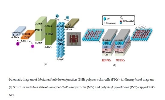
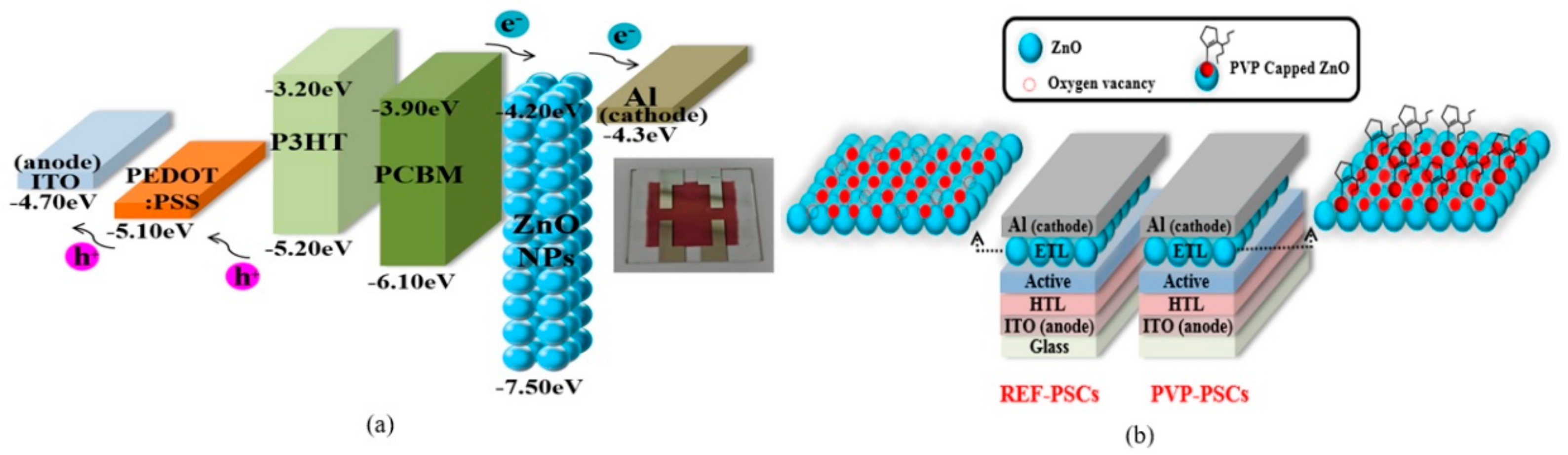
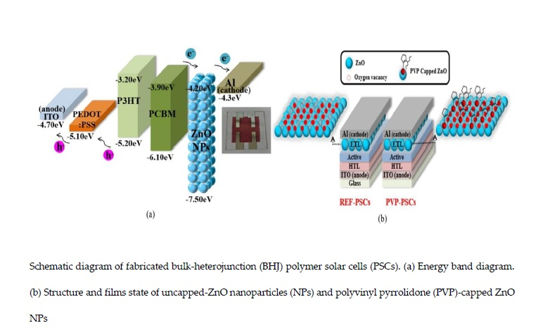
Effect of PVP-Capped ZnO Nanoparticles with Enhanced Charge Transport on the Performance of P3HT/PCBM Polymer Solar Cells

 , , , ,
  and
and
Abstract
:
1. Introduction
2. Experimental
3. Results and Discussion
4. Conclusions
Author Contributions
Funding
Acknowledgments
Conflicts of Interest
References
- Hoth, C.N.; Schilinsky, P.; Choulis, S.A.; Brabec, C.J. Printing highly efficient organic solar cells. Nano Lett. 2008, 8, 2806–2813. [Google Scholar] [CrossRef] [PubMed]
- Liang, Y.; Xu, Z.; Xia, J.; Tsai, S.T.; Wu, Y.; Li, G. For the bright future—bulk heterojunction polymer solar cells with power conversion efficiency of 7.4%. Adv. Mater. 2010, 22, 135–138. [Google Scholar] [CrossRef] [PubMed]
- Li, L.; Li, Z.; Feng, K.; Xu, X.; Wang, L. Development of large band-gap conjugated copolymers for efficient regular single and tandem organic solar cells. J. Am. Chem. Soc. 2013, 135, 13549–13557. [Google Scholar] [CrossRef] [PubMed]
- Tang, C.W. Two-layer organic photovoltaic cell. Appl. Phys. Lett. 1985, 48, 183–185. [Google Scholar] [CrossRef]
- Cheng, Y.J.; Yang, S.H.; Hsu, C.S. Synthesis of conjugated polymers for organic solar cell applications. Chem. Rev. 2009, 109, 5868–5923. [Google Scholar] [CrossRef]
- Singh, S.P.; Sharma, G.D. Near Infrared Organic Semiconducting Materials for Bulk Heterojunction and Dye-Sensitized Solar Cells. Chem. Rec. 2014, 14, 419–481. [Google Scholar] [CrossRef]
- Gopalan, S.-A.; Gopalan, A.-I.; Vinu, A.; Lee, K.P.; Kang, S.W. A new optical-electrical integrated buffer layer design based on gold nanoparticles tethered thiol containing sulfonated polyaniline towards enhancement of solar cell performance. Sol. Energy Mater. Sol. Cells 2018, 174, 112–123. [Google Scholar] [CrossRef]
- Nemnes, G.A.; Iftimie, S.; Palici, A.; Nicolaev, A.; Mitran, T.L.; Radu, A.; Antohe, S. Optimization of the structural configuration of ICBA/P3HT photovoltaic cells. Appl. Surf. Sci. 2017, 424, 264–268. [Google Scholar] [CrossRef]
- Li, G.; Chu, C.W.; Shrotriva, V.; Huang, J.; Yang, Y. Efficient inverted polymer solar cells. Appl. Phys. Lett. 2006, 88, 253503. [Google Scholar] [CrossRef] [Green Version]
- Hoven, G.V.; Dang, D.X.; Coffin, R.C.; Peet, J.; Nguyen, T.Q.; Bazan, G.C. Improved performance of polymer bulk heterojunction solar cells through the reduction of phase separation via solvent additives. Adv. Mater. 2010, 22, E63–E66. [Google Scholar] [CrossRef]
- Su, M.S.; Kuo, C.Y.; Yuan, M.C.; Jeng, U.; Su, C.J.; Wei, K.H. Improving device efficiency of polymer/fullerene bulk heterojunction solar cells through enhanced crystallinity and reduced grain boundaries induced by solvent additives. Adv. Mater. 2011, 23, 3315–3319. [Google Scholar] [CrossRef] [PubMed]
- Jacobs, I.E.; Wang, F.; Valdez, Z.I.B.; Oviedo, A.N.A.; Bilsky, D.J.; Moulé, A.J. Photoinduced degradation from trace 1, 8-diiodooctane in organic photovoltaics. J. Mater. Chem. C 2018, 6, 219–225. [Google Scholar] [CrossRef]
- Steim, R.; Kogler, F.R.; Brabec, C.J. Interface materials for organic solar cells. J. Mater. Chem. 2010, 20, 2499–2512. [Google Scholar] [CrossRef]
- de Jong, M.P.; van Ijzendoorn, L.J.; de Voigt, M.J.A. Stability of the interface between indium-tin-oxide and poly (3, 4-ethylenedioxythiophene)/poly (styrenesulfonate) in polymer light-emitting diodes. Appl. Phys. Lett. 2000, 77, 2255–2257. [Google Scholar] [CrossRef]
- Chen, L.; Wang, P.; Li, F.; Yu, S.; Chen, Y. Efficient bulk heterojunction polymer solar cells using PEDOT/PSS doped with solution-processed MoO3 as anode buffer layer. Sol. Energy Master. Sol. Cells. 2012, 102, 66–70. [Google Scholar] [CrossRef]
- Ratcliff, E.L.; Meyer, J.; Steirer, K.X.; Armstrong, N.R.; Olson, D.; Kahn, A. Energy level alignment in PCDTBT: PC70BM solar cells: Solution processed NiOx for improved hole collection and efficiency. Org. Electron. 2012, 13, 744–749. [Google Scholar] [CrossRef]
- Chang, Y.M.; Leu, C.Y. Solvent extraction induced nano-porous zinc oxide as an electron transport layer for inverted polymer solar cells. Org. Electron. 2012, 12, 2991–2996. [Google Scholar] [CrossRef]
- Yang, P.; Zhou, X.; Cao, G.; Luscombe, C.K. P3HT: PCBM polymer solar cells with TiO2 nanotube aggregates in the active layer. J. Mater. Chem. 2010, 20, 2612–2616. [Google Scholar] [CrossRef]
- Sun, Y.; Seo, J.H.; Takacs, C.J.; Seifter, J.; Heeger, A.J. Inverted polymer solar cells integrated with a low-temperature-annealed sol–gel-derived ZnO film as an electron transport layer. Adv. Mater. 2011, 23, 1679–1683. [Google Scholar] [CrossRef]
- Lee, Y.I.; Youn, J.H.; Ryu, M.S.; Kim, J.; Moon, H.T.; Jang, J. Highly efficient inverted poly (3-hexylthiophene): Methano-fullerene [6,6]-phenyl C71-butyric acid methyl ester bulk heterojunction solar cell with Cs2CO3 and MoO3. Org. Electron. 2011, 12, 353–357. [Google Scholar] [CrossRef]
- Huang, X.; Yu, H.; Shi, S.; Huang, C. Improving the performance of inverted polymer solar cells by the efficiently doping and modification of electron transport layer-ZnO. Org. Electron. 2019, 65, 311–320. [Google Scholar]
- Litzov, I.; Brabec, C.J. Development of efficient and stable inverted bulk heterojunction (BHJ) solar cells using different metal oxide interfaces. Materials 2013, 6, 5796–5820. [Google Scholar] [CrossRef] [PubMed]
- Baglio, V.; Girolamo, M.; Antonucci, V.; Arico, A.S. Influence of TiO2 film thickness on the electrochemical behaviour of dye-sensitized solar cells. Int. J. Electrochem. Sci. 2011, 6, 3375–3384. [Google Scholar]
- Hadipour, A.; Maller, R.; Heremans, P. Room temperature solution-processed electron transport layer for organic solar cells. Org. Electron. 2013, 14, 2379–2386. [Google Scholar] [CrossRef]
- Wiranwetchayan, O.; Liang, Z.; Zhang, Q.; Cao, G.; Singjai, P. The role of oxide thin layer in inverted. Mater. Sci. Appl. 2011, 2, 1697–1701. [Google Scholar]
- Jagadamma, L.K.; Abdelsamie, M.; Labban, A.; Aresu, E.; Ndjawa, G.O.N.; Anjum, D.H.; Cha, D.K.; Beaujuge, P.M.; Amassian, A. Efficient inverted bulk-heterojunction solar cells from low-temperature processing of amorphous ZnO buffer layers. J. Mater. Chem. A 2014, 2, 13321–13331. [Google Scholar] [CrossRef]
- Iwan, A.; Palewicz, M.; Tazbir, I.; Boharewicz, B.; Pietruszka, R.; Filapek, M.; Wojtkiewicz, J.; Witkowski, B.S.; Granek, F.; Godlewski, M. Influence of ZnO: Al, MoO3 and PEDOT: PSS on efficiency in standard and inverted polymer solar cells based on polyazomethine and poly (3-hexylthiophene). Electrochim. Acta 2016, 191, 784–794. [Google Scholar] [CrossRef]
- Gilot, J.; Barbu, I.; Wienk, M.M.; Janssen, R.A.J. The use of ZnO as optical spacer in polymer solar cells: theoretical and experimental study. Appl. Phys. Lett. 2007, 91, 113520. [Google Scholar] [CrossRef]
- Liu, C.; Yi, C.; Wang, K.; Yang, Y.; Bhatta, R.S.; Tsige, M.; Xiao, S.; Gong, X. Single-junction polymer solar cells with over 10% efficiency by a novel two-dimensional donor–acceptor conjugated copolymer. Appl. Mater. Interfaces 2015, 7, 4928–4935. [Google Scholar] [CrossRef]
- Janotti, A.; van de Walle, C.G. Oxygen vacancies in ZnO. Appl. Phys. Lett. 2005, 87, 122102. [Google Scholar] [CrossRef]
- Meulenkamp, E.A. Synthesis and growth of ZnO nanoparticles. J. Phys. Chem. B 1998, 102, 5566–5572. [Google Scholar] [CrossRef]
- Kavitha, M.K.; Jinesh, K.B.; Philip, R.; Gopinath, P.; John, H. Defect engineering in ZnO nanocones for visible photoconductivity and nonlinear absorption. Phys. Chem. Chem. Phys. 2014, 16, 25093–25100. [Google Scholar] [CrossRef] [PubMed]
- Singh, A.K.; Viswanath, V.; Janu, V.C. Synthesis, effect of capping agents, structural, optical and photoluminescence properties of ZnO nanoparticles. J. Lumin. 2009, 129, 874–878. [Google Scholar] [CrossRef]
- Tachikara, S.; Noguchi, A.; Tsuge, T.; Hara, M.; Odawara, O.; Wada, H. Optical properties of ZnO nanoparticles capped with polymers. Materials 2011, 4, 1132–1143. [Google Scholar] [CrossRef]
- Xiong, H.-M. Photoluminescent ZnO nanoparticles modified by polymers. J. Mater. Chem. 2010, 20, 4251–4262. [Google Scholar] [CrossRef]
- Gutul, T.; Rusu, E.; Condur, N.; Ursaki, V.; Goncearenco, E.; Vlazan, P. Preparation of poly (n-vinylpyrrolidone)-stabilized ZnO colloid nanoparticles. Beilstein J. Nanotechnol. 2014, 5, 402–406. [Google Scholar] [CrossRef]
- Kamari, H.; Al-Hada, N.; Saion, E.; Shaari, A.; Talib, Z.; Flaifel, M.; Ahmed, A. Calcined solution-based PVP influence on ZnO semiconductor nanoparticle properties. Crystals 2017, 7, 2. [Google Scholar] [CrossRef]
- Bawendi, M.G.; Steigerwald, M.L.; Brus, L.E. The quantum mechanics of larger semiconductor clusters (quantum dots). Annu. Rev. Phys. Chem. 1990, 41, 477–496. [Google Scholar] [CrossRef]
- Quang, N.H.; Truc, N.T.; Niquet, Y.M. Tight-binding versus effective mass approximation calculation of electronic structures of semiconductor nanocrystals and nanowires. Comput. Mater. Sci. 2008, 44, 21–25. [Google Scholar] [CrossRef]
- Tahir, N.; Hassain, S.T.; Usman, M.; Hasanain, S.K.; Mumtaz, A. Effect of vanadium doping on structural, magnetic and optical properties of ZnO nanoparticles. Appl. Surf. Sci. 2009, 255, 8506–8510. [Google Scholar] [CrossRef]
- Sui, X.; Liu, Y.; Shao, C.; Liu, Y.; Xu, C. Structural and photoluminescent properties of ZnO hexagonal nanoprisms synthesized by microemulsion with polyvinyl pyrrolidone served as surfactant and passivant. Chem. Phys. Lett. 2006, 424, 340–344. [Google Scholar] [CrossRef]
- Ilegbusi, O.; Trakhtenberg, L. Synthesis and Conductometric Property of Sol–Gel-Derived ZnO/PVP Nano Hybrid Films. J. Mater. Eng. Perform. 2013, 22, 911–915. [Google Scholar] [CrossRef]
- Bak, G.W.; Lipinski, A. space charge-limited currents in thin film solid dielectrics with non-uniform deep-trap distributions: numerical solutions. Thin Solid Films 1994, 238, 290–294. [Google Scholar] [CrossRef]
- Han, B.; Gopalan, S.-A.; Lee, K.D.; Kang, B.H.; Lee, S.W.; Lee, J.S.; Kwon, D.H.; Lee, S.H.; Kang, S.W. Preheated solvent exposure on P3HT:PCBM thin film: A facile strategy to enhance performance in bulk heterojunction photovoltaic cells. Curr. Appl. Phys. 2014, 12, 1443–1450. [Google Scholar] [CrossRef]


| ETL | PVP Volume | Particle Size (nm) | Bandgap (Eg) (eV) |
|---|---|---|---|
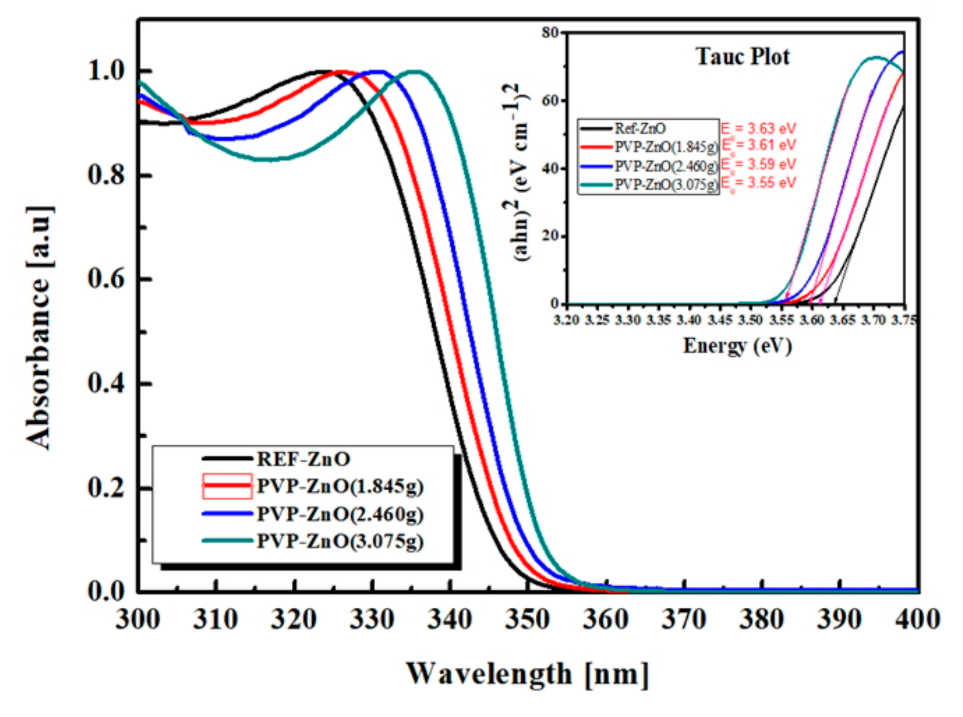
| REF-ZnO | - | 3.06 | 3.63 |
| PVP-ZnO (1.845g) | 1.845g | 3.15 | 3.61 |
| PVP-ZnO (2.460g) | 2.460g | 3.23 | 3.59 |
| PVP-ZnO (3.075g) | 3.075g | 3.39 | 3.55 |
| ETL | VOC (V) | JSC (mA/cm2) | RS (ohm) | FF | PCEa (%) | PCEb (%) |
|---|---|---|---|---|---|---|
| REF-ZnO | 0.593 ± 0.012 | 6.327 ± 0.002 | 139 ± 3.1 | 0.645 ± 0.034 | 2.49 | 2.46 ± 0.008 |
| PVP-ZnO (0.615 g) | 0.609 ± 0.004 | 6.840 ± 0.003 | 171 ± 2.9 | 0.580 ± 0.049 | 2.58 | 2.42 ± 0.024 |
| PVP-ZnO (1.230 g) | 0.616 ± 0.008 | 6.666 ± 0.004 | 159 ± 5.0 | 0.616 ± 0.056 | 2.59 | 2.53 ± 0.015 |
| PVP-ZnO (1.845 g) | 0.622 ± 0.004 | 6.132 ± 0.009 | 159 ± 8.1 | 0.629 ± 0.104 | 2.85 | 2.62 ± 0.073 |
| PVP-ZnO (2.460 g) | 0.617 ± 0.004 | 7.423 ± 0.004 | 138 ± 5.7 | 0.652 ± 0.072 | 3.08 | 2.98 ± 0.024 |
| PVP-ZnO (3.075 g) | 0.611 ± 0.004 | 7.277 ± 0.001 | 128 ± 1.2 | 0.662 ± 0.017 | 2.98 | 2.94 ± 0.008 |
| PVP-ZnO (3.690 g) | 0.614 ± 0.001 | 7.051 ± 0.003 | 164 ± 5.0 | 0.641 ± 0.044 | 2.85 | 2.78 ± 0.014 |
© 2019 by the authors. Licensee MDPI, Basel, Switzerland. This article is an open access article distributed under the terms and conditions of the Creative Commons Attribution (CC BY) license (http://creativecommons.org/licenses/by/4.0/).
Share and Cite
Kim, O.; Kwon, J.; Kim, S.; Xu, B.; Seo, K.; Park, C.; Do, W.; Bae, J.; Kang, S. Effect of PVP-Capped ZnO Nanoparticles with Enhanced Charge Transport on the Performance of P3HT/PCBM Polymer Solar Cells. Polymers 2019, 11, 1818. https://doi.org/10.3390/polym11111818
Kim O, Kwon J, Kim S, Xu B, Seo K, Park C, Do W, Bae J, Kang S. Effect of PVP-Capped ZnO Nanoparticles with Enhanced Charge Transport on the Performance of P3HT/PCBM Polymer Solar Cells. Polymers. 2019; 11(11):1818. https://doi.org/10.3390/polym11111818
Chicago/Turabian StyleKim, OkSik, JinBeom Kwon, SaeWan Kim, Binrui Xu, KyeongHo Seo, CheolEon Park, WooJong Do, JinHyuk Bae, and ShinWon Kang. 2019. "Effect of PVP-Capped ZnO Nanoparticles with Enhanced Charge Transport on the Performance of P3HT/PCBM Polymer Solar Cells" Polymers 11, no. 11: 1818. https://doi.org/10.3390/polym11111818
APA StyleKim, O., Kwon, J., Kim, S., Xu, B., Seo, K., Park, C., Do, W., Bae, J., & Kang, S. (2019). Effect of PVP-Capped ZnO Nanoparticles with Enhanced Charge Transport on the Performance of P3HT/PCBM Polymer Solar Cells. Polymers, 11(11), 1818. https://doi.org/10.3390/polym11111818