Article

Mesoscopic Detection of the Influence of a Third Component on the Self-Assembly Structure of A2B Star Copolymer in Thin Films

1
College of Chemistry Chemical Engineering and Materials Science, Zaozhuang University, Zaozhuang 277160, China
2
Advanced Photonics Center, Southeast University, 2# Sipailou, Nanjing 210096, China
3
Zaozhuang Key Laboratory of Functional Materials, Zaozhuang 277160, China
4
Opto-Electronic Engineering College, Zaozhuang University, Zaozhuang 277160, China
*
Author to whom correspondence should be addressed.
Polymers 2019, 11(10), 1636; https://doi.org/10.3390/polym11101636
Submission received: 10 September 2019 / Revised: 4 October 2019 / Accepted: 8 October 2019 / Published: 10 October 2019
(This article belongs to the Special Issue Simulations of Polymers II)

Abstract

:
The most common self-assembly structure for A2B copolymer is the micellar structure with B/A segments being the core/corona, which greatly limits its application range. Following the principle of structure deciding the properties, a reformation in the molecular structure of A2B copolymer is made by appending three segments of a third component C with the same length to the three arms, resulting (AC)2CB 3-miktoarm star terpolymer. A reverse micellar structure in self-assembly is expected by regulating the C length and the pairwise repulsive strength of C to A/B, aiming to enrich its application range. Keeping both A and B lengths unchanged, when the repulsion strength of C to A is much stronger than C to B, from the results of mesoscopic simulations we found, with a progressive increase in C length, (AC)2CB terpolymer undergoes a transition in self-assembled structures, from a cylindrical structure with B component as the core, then to a deformed lamellar structure, and finally to a cylindrical structure with A component as the core. This reverse micellar structure is formed with the assistance of appended C segments, whose length is longer than half of B length, enhancing the flexibility of three arms, and further facilitating the aggregation of A component into the core. These results prove that the addition of a third component is a rational molecular design, in conjunction with some relevant parameters, enables the manufacturing of the desired self-assembly structure while avoiding excessive changes in the involved factors.

Graphical Abstract

1. Introduction

The chemically dissimilar linked units in block copolymers facilitate the occurrence of micro-separation, resulting in their self-assembly into rich ordered nanostructures, which have significant potential in applications such as nanowire [1], membranes [2], metamaterials [3,4], lithography [5,6], and so on. In addition to the block ratios and the interaction strength between constituting blocks, the chain architecture of block copolymers is also a well-known parameter influencing this self-assembly behavior. For example, take AB-type copolymers, whose architecture can be varied by changes in the number of repeating blocks and the chain topology, such as the simplest linear AB diblock [7], linear ABA triblock [8,9,10,11,12], ABn miktoarm star [13,14,15,16,17], (AB)n star [18,19,20,21], comb [22,23,24], ABAB… [25,26,27,28,29,30], (BAB)n star [31,32], etc., form a wide range of structures, including body-centered cubic spheres, hexagonally-packed cylinders, bicontinuous gyroids and parallel lamellae, the perforated lamellar phase and σ phase. Gido’s group constructed the full phase diagram of A2B miktoarm copolymer systems, and some special morphological transformations were presented [33,34]. Recently, Li’s group examined the self-assembly of ABAT block copolymers, which are composed of an AB diblock copolymer with an extra A block tethered onto the B block, using the self-consistent field theory. They found that the phase behavior depends sensitively on the topology. The local segregation of the two different kinds of blocks constrained by the chain architecture regulating the local interfacial curvature, even influencing the phase behavior, was also determined.
Theoretically speaking, increasing the number of block types can enrich the number of accessible self-assembled nanostructures, thus, an ABC triblock terpolymer, constructed by the introduction of an additional block to an AB diblock, can generate fascinating periodic structures that are not found in an AB diblock copolymer; for example, hamburger-like micelles, segmented worm-like micelles, raspberry-like micelles, double and triple helices, etc. [35,36,37,38,39]. However, owing to the rapid expansion of the parameter space, the increase in the number of block types brings great challenges to structure searching and control [40]. A further illustration starts from the simplest linear AB diblock copolymer, which is modeled via two parameters (i.e., χABN and fA, where χAB is the Flory–Huggins interaction parameter, N is the chain length, and fA is the chain length ratio of A component). When one additional block type is introduced, an ABC triblock copolymer is constructed, and at least five parameters are needed, i.e., χABN, χBCN, χACN, fA, and fB. If the number of block types increases further, the number of parameters to describe the model will be dramatically expanded to the extent that is hard to bear.
In our previous work, two types of AnB miktoarm star copolymers were studied—one was an H-shaped structure [41], and the other was a Y-shaped structure [42]. Both copolymer thin film systems were self-assembled into a hexagonal cylindrical arrangement; especially, the extra A arm in the chain architecture makes the phase behavior of the H-shaped copolymer different from that of the Y-shaped copolymer. Compared with the Y-shaped copolymer thin film, the regulation of the cylindrical size in the H-shaped copolymer thin film is completed with the aid of vacancies; thus, the resultant size distribution is wider. However, the self-assembled cylinders are all composed of B component as the core, which limits its function. In view of the new structure implying new functions and properties, the search for the formation conditions of the reverse micelle is essential and is beneficial to expand the potential function via the reformation of the chain architecture. Inspired by the increase in the block types prompting more abundant self-assembled structures, the according growth in the number of descriptive parameters is also taken into account, and a third component is introduced into each arm of a Y-shaped copolymer, generating a resultant (AC)2CB 3-miktoarm star terpolymer. Furthermore, the corresponding self-assembly mechanism of the reverse micelle is also illustrated.

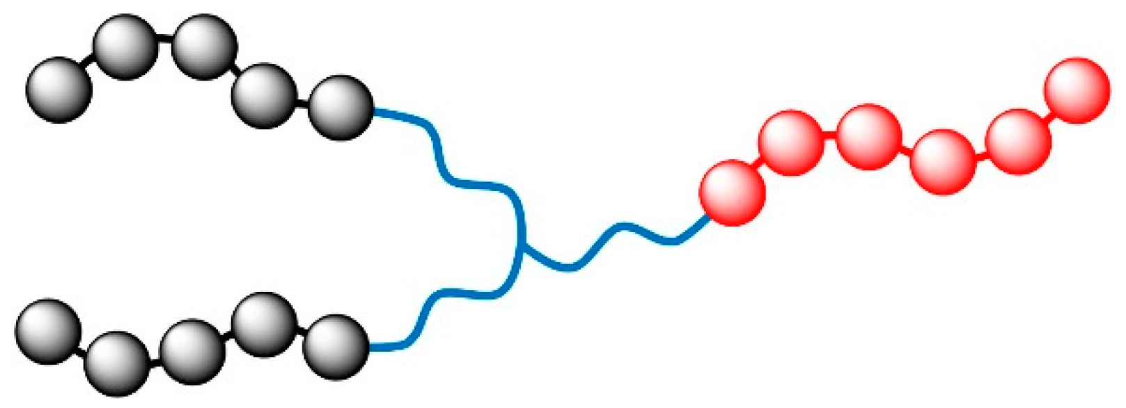
2. Models and Parameter Settings

Mesoscopic modeling is a flexible and powerful theoretical tool to study inhomogeneous polymeric systems. Among the various modeling methods, MesoDyn has been validated as an effective approach to explore the phase behavior of polymer systems at the mesoscale [43,44,45,46,47,48]. Furthermore, MesoDyn facilitates treating various chain architectures of polymers, from linear [49] to branched [41,42,50]; MesoDyn is a mature method to investigate the phase behavior of flexible block copolymers.
The detailed derivation and theory of MesoDyn is readily found in several reports, so only a brief description is given here. The intrinsic theory of the MesoDyn method is based on the dynamic mean-field theory developed by Fraaije [51,52]. Here, the phase separation dynamics and ordering processes of the polymeric systems are described by Langevin equations, and the Gaussian chain density functionals are established between the external potential fields and the density fields for each bead type by a one-to-one correspondence. Moreover, the intrinsic chemical potentials are the functionals of the external potentials and density fields. Hence, the coupled Langevin equations are capable of describing the relationship between the time derivatives and the intrinsic chemical potentials. As a result of the association between the noise source and the exchange kinetics coefficients, a closed set is formed to be efficiently integrated into a cubic mesh for the iteration of the inner loop by a Crank–Nicholson scheme [53]. When all beads are treated with the same size for simplicity, the chain topology primarily depends on the coarse-graining mode.
In consideration of keeping the main frame of polymer unchanged, the topological structure of the A2B 3-miktoarm star is preserved, and three segments consisting of a third component (C) are inserted along the three arms from the junction point, forming an (AC)2CB 3-miktoarm star terpolymer composed of two copolymer arms of AC and one copolymer arm of CB, whose schematic structure is shown in Scheme 1. Furthermore, the numbers of A and B beads in each segment are also reserved as 5 and 6, respectively, and the interaction parameter between A and B beads is set as 4.68 kJ·mol-1; therefore, both are kept the same as that in our previous work [42]. The three appended C segments are the same length, and the number of C beads in each C segment is progressively increased from 1 to 6, resulting in six individual systems, named as 3C1, 3C2, 3C3, 3C4, 3C5, and 3C6 systems (additionally, the name for the system without C segment is C0). Apart from the chain length of the C segments, the interactions of C beads with A and B beads are also examined. Thus, four pairwise interactions are taken into account, i.e., ECA = 0 kJ·mol−1 and ECB = 0 kJ·mol−1, ECA = 5 kJ·mol−1 and ECB = 5 kJ·mol−1, ECA = 1 kJ·mol−1 and ECB = 5 kJ·mol−1, and ECA = 5 kJ·mol−1 and ECB = 1 kJ·mol−1, which are referred to as C[00], C[55], C[15], and C[51], respectively, and all the interaction parameters are listed in Table 1. From the comparison of C beads with A and B beads, the former two belong to non-preferential interactions, i.e., there is no preference for the C bead to interact with either A or B bead; whereas, the latter two belong to preferential interactions, where the affinity of the C bead lies with A beads and B beads for C[15] and C[51], respectively.
Compared with three dimensions (3D), some structures that result from the simulation in two dimensions (2D) may be missed, such as bi- or tri-continuous gyroid structures. However, in industry, many materials, benefiting from 2D ordered structures fabricated in thin films, manifest great potential, which reveals the structure control in 2D space possesses an essential significance that cannot be replaced. Therefore, all the simulations in this paper are carried out in the Lx × Ly × Lz spatial lattice of a 50 × 50 × 5 nm3 grid, whose width in the Z axis is 10% of the width in either the X or Y axis, to model thin films. Additionally, the bond length is set as 1.1543 to ensure the isotropy of all grid-restricted operators. To neglect the size influence on self-assembly, all beads are an equal size of 0.01 nm3 for simplicity. In MesoDyn simulations, the bead diffusion coefficient provides the link between the real timescale of the simulation and the dimensionless units, and a default value of 1.0 × 10⁻⁷ cm2·s-1 is adopted. Owing to the inverse relationship of the dimensionless noise parameter to the level of thermal noise applied, a maximum value of 100 for the noise-scaling parameter is employed to realize the minimum in noise. Lastly, the compressibility parameter is fixed at 10.0, the dimensionless time step is set as 0.5, and each simulation is carried out at a constant temperature of 400 K for 1.0 × 10⁵ steps (i.e., 5 ms).

3. Results and Discussion

Most of systems assemble into cylindrical structures, whose average sizes are readily calculated and are shown in Figure 1. For a clear comparison of the reformation of the molecular structure, the systems with only one C bead as the joint point in the A2B topology are also simulated under the interaction situation of C[00], C[55], C[15], and C[51]. The relatively low composition of C beads compared with that of A and B beads, as well as the innermost location of the C bead, both severely restrict the C bead’s influence on the other components, resulting in no apparent difference in the average sizes under various interaction conditions. With the increase in the length of the C segment, the tendencies in the change of the average size under various conditions present evident differences. Only the average sizes of systems with the C[00] interaction show an almost direct proportional change tendency with the increasing length of each C segment. For the same kind of non-preferential interaction of C[55], whose change tendency for the average size is similar to that of C[00], the strong repulsion of C beads to both A and B beads results in a larger average size than that of C[00]. Particularly, the 3C4 system exhibits the highest value of the average size and breaks the monotonically increasing tendency of average size, which will be given a detailed analysis later. With increasing C beads, the change tendency for the average sizes with C[15] interaction approximately rises at first and then decreases. Except for the 3C3 system, whose average size is the highest and higher than the same system with the C[00] interaction, the other systems with the C[15] interaction all possess an average size that is less than that of the corresponding system with the C[00] interaction. The systems with the C[51] interaction are relatively complicated, as only the single addition of a C bead per C segment results in a tremendous increase in the average size of the 3C1 system. Then, two non-cylindrical structures are formed for 3C2 and 3C3 systems. Finally, the 3C4, 3C5 and 3C6 systems are cylindrical in structure, but the constituent components of the core and shell are reversed, and a decreasing trend for their average sizes is displayed.
Taking the 3C4 system as an example, from a track of average size with time shown in Figure 2, different tendencies under various interaction conditions are found. Clearly different from the trend of the other lines, C[00] presents a decreasing trend, which reveals the splitting mechanism of the assembled micelles. Moreover, the non-preference, as well as an even lack of interaction, of C beads and A and B beads, and the innermost location of the C component enlarging the distance between A and B component both result in a weakening interaction between the A and B components, making the formation of regular micelles unstable. Therefore, the largest amplitude of variation for C[00] can be interpreted. Both the curves of C[15] and C[55] exhibit a stepwise-increasing trend, indicating the fusion mechanism of the assembled micelles. Compared to the C[15] interaction, the non-preferential but strong repulsion between C beads to both A and B beads under the C[55] interaction intensifies the competition for forming a core and shell composition, which needs more steps in the fusing of small micelles into large micelles, costing more time for the adjustment process. A reverse micellar structure is generated under the C[51] interaction. The stronger repulsion between C and A beads immediately facilitates the initial formation of the core, so there is nearly no evident fusing process responsible for converting small micelles into large micelles. Additionally, the weaker repulsion between C beads to B beads is helpful in stabilizing the assembled micelles, resulting in the smallest amplitude of variation in average size.

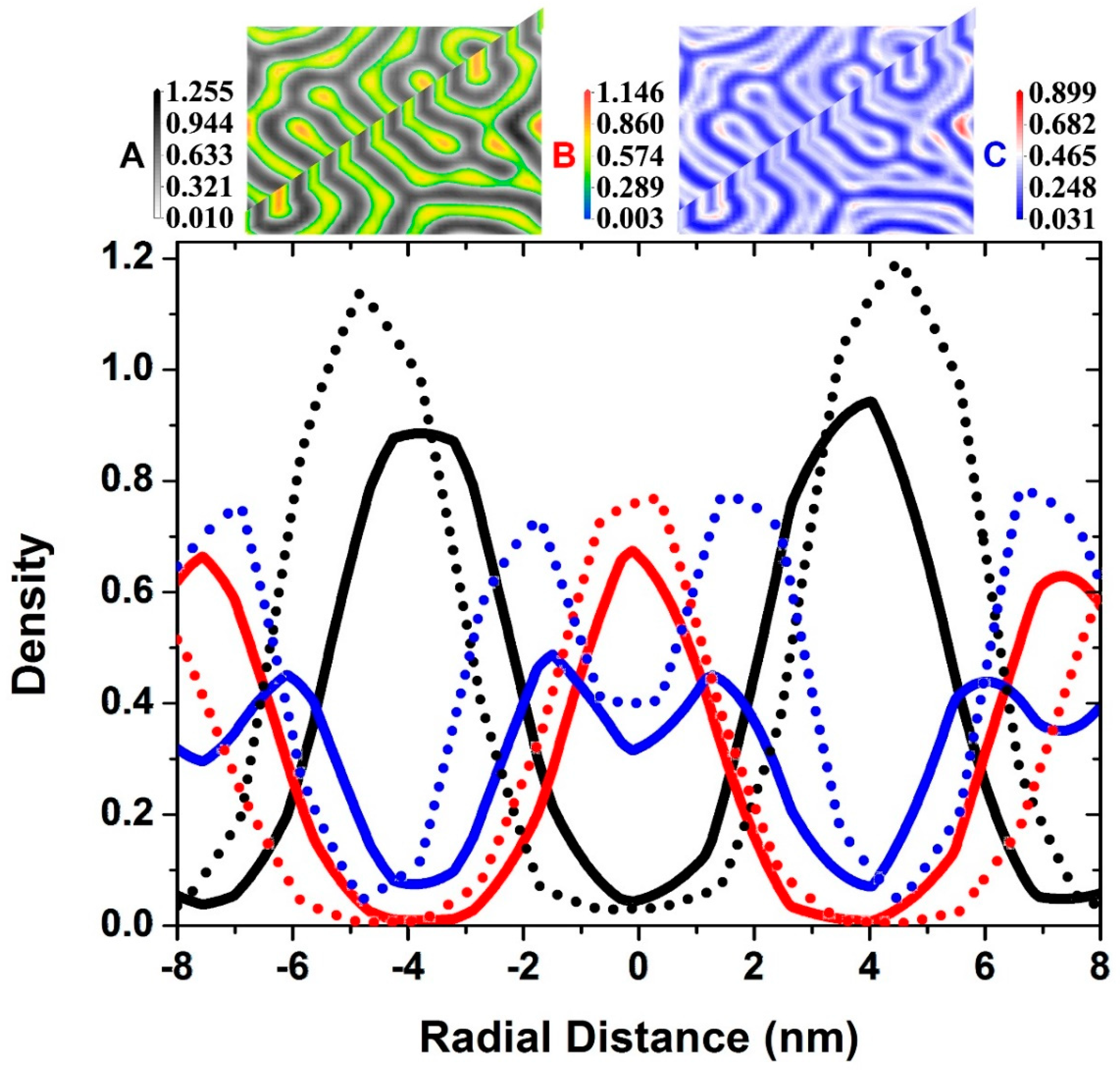
3.1. Self-Assembly under Non-Preferential Interactions

The C[00] and C[55] interactions are two typical representatives of non-preferential interactions, but their distinctly different repulsive strengths for the interaction between C beads and A and B beads cause their different self-assembly structures, as shown in Figure 3. For the C[00] interaction, a lack of interaction between C beads and both A and B beads does not give rise to influence over B beads in the core and A beads in the corona, or to influence over the wide distribution of C beads with a relatively high density. Conversely, for the C[55] interaction, not only does a squeezing effect generated from the strong repulsion between C beads to both A and B beads favor the concentration of an A bead-aggregating zone and B bead-aggregating zone, respectively, but also the steric hindrance from C beads located between A and B beads contributes to producing a wide range of core regions; consequently, the final configuration is equivalent to a vesicle structure, if one does not take component C into account. A detailed illustration of the fusing mechanism of the self-assembly is made in the Figure S1–S3 of Supplementary Materials part via three representative analyses of the density distribution.

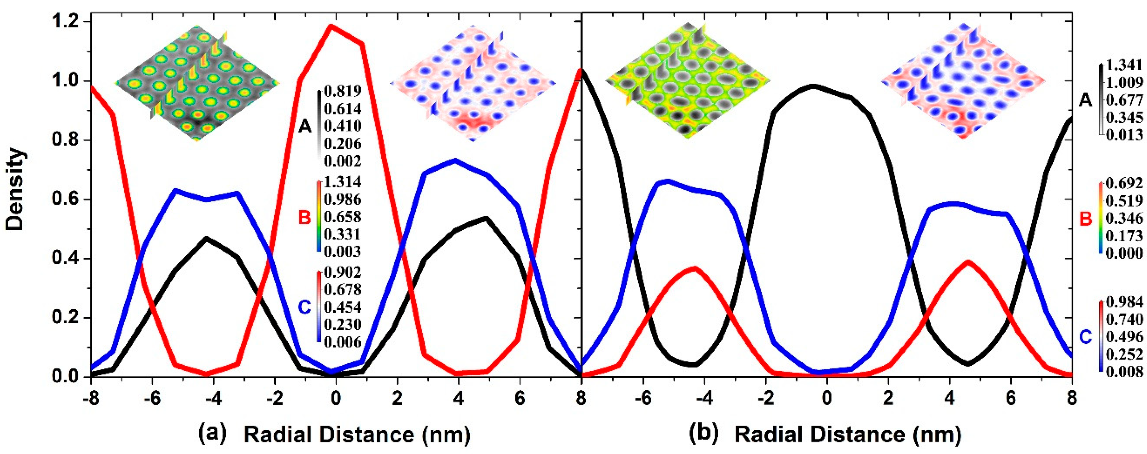
3.2. Two Transitional Systems

As shown in Figure 1, three different structures are produced with increasing numbers of C beads, i.e., the cylindrical structure with B beads constituting the core part (C0 and 3C1 systems), deformed lamellar structure (3C2 and 3C3 systems), and cylindrical structure with A beads constituting the core part (3C4, 3C5, and 3C6 systems) for C[51] interactions. Thus, the two intermediate systems, 3C2 and 3C3, are regarded as the transition from the regular cylindrical micellar structure to the reverse cylindrical micellar structure, whose density profiles are shown in Figure 4. The same change tendency occurs for the same constituting beads in the 3C2 and 3C3 systems, indicating the same kind of assembled structure. However, compared with the 3C2 system, the 3C3 system presents two distinct differences: One is the relatively larger distance between the same kinds of aggregates, and the other is the relatively higher peak value in the density profiles consisting of the same component, which can be understood from the steric hindrance and strong repulsion from C beads. Due to the location of the C beads accumulating between adjacent A aggregates and B aggregates, the increase in C beads of the 3C3 system leads to more occupation of C aggregates. The strong repulsion from more C beads, resulting in both A aggregates and B aggregates being ‘pushed’ far away from C aggregates, presents as relatively larger distances between the same kind of aggregates. Moreover, every A aggregate or B aggregate is sandwiched in the middle by two C aggregates, with the increasing repulsion resulting from the additional C beads enhancing the ‘squeezing effect’, causing the A beads or B beads to be ‘squeezed’ inward, and this action represents the relatively higher peak value of the density profiles consisting of the same component. Different from the regular cylindrical structure with the B beads as the definite core part and the A/C beads surrounding, there is no definition for the core or shell in the deformed lamellar structure, only the duplication of A aggregates to C aggregates to B aggregates to C aggregates can be determined. Therefore, as an inference, the possibility of forming the reverse cylindrical micellar structure when further C beads are added to the inserted C segments, advancing the flexibility of both A and B segments, can be reasonably introduced.

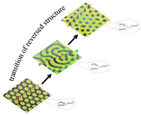
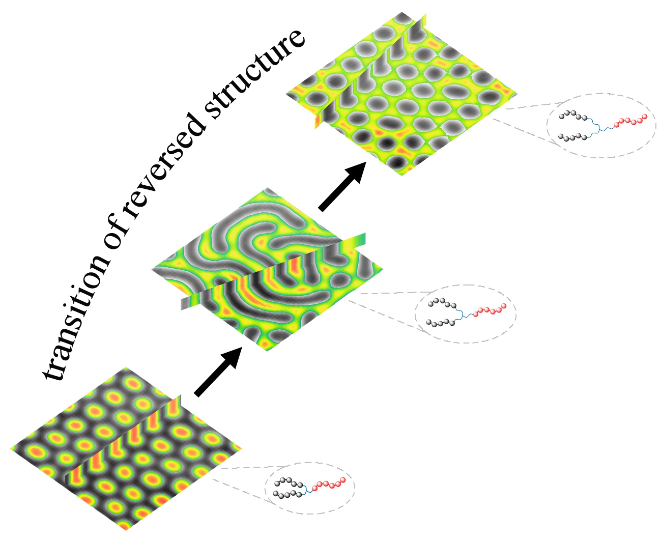
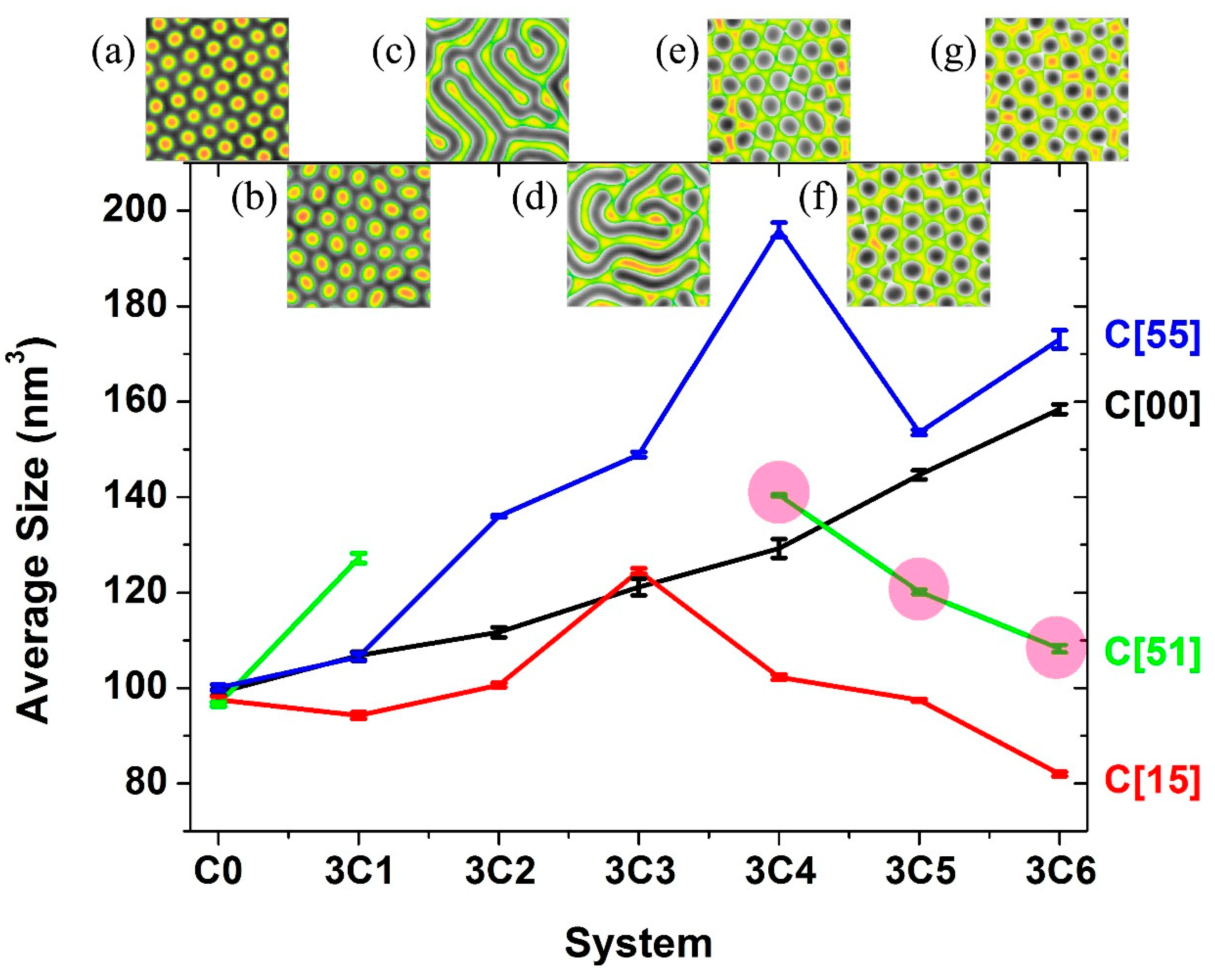
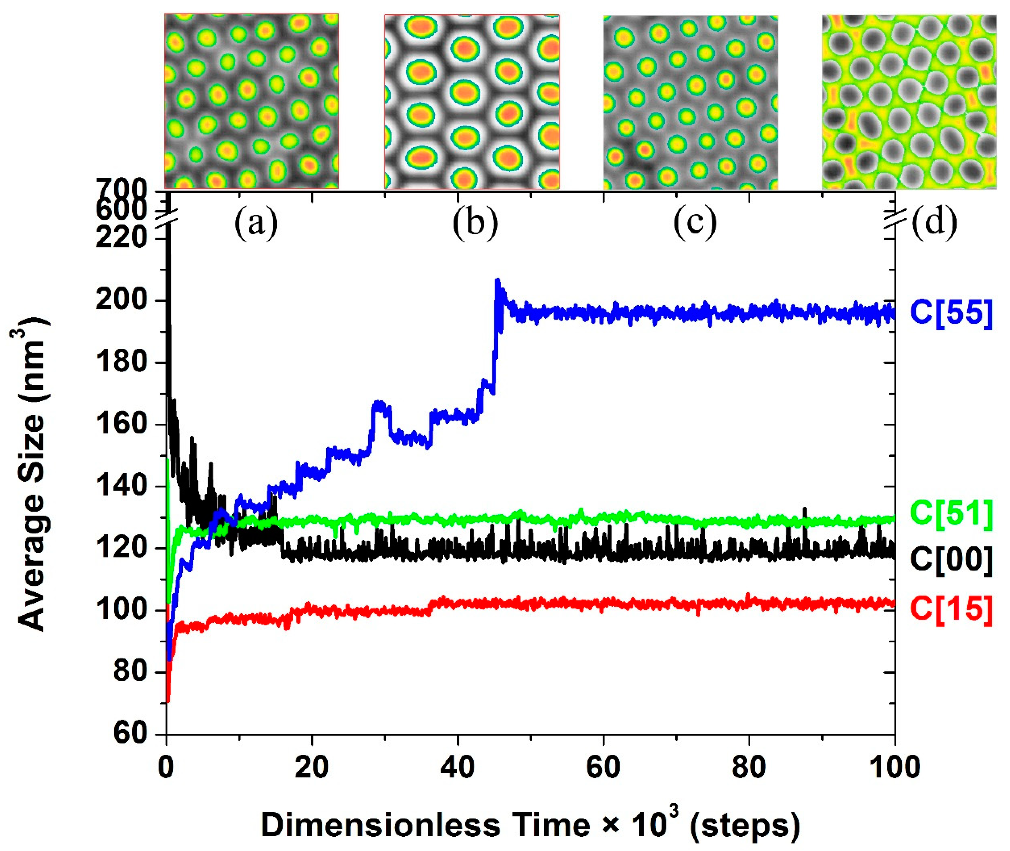
3.3. The Self-Assembly of the Reverse Cylindrical Micellar Structure

For comparison, the same kind of density profiles for the 3C4 system affected by the C[15] interaction are shown in Figure 5a, whereby the interaction between C beads and B beads is significantly stronger than that between C beads and A beads. In this case, the C aggregates are dramatically separated from the B aggregates, whereas the C aggregates share the same location with the A aggregates, and both play the role of the shell. As predicted, when the inserted number of C beads in each C segment grows to four or even more, the resultant systems self-assemble into the reverse cylindrical micellar structure under the C[51] interaction, and the density profiles of the 3C4 system affected by the C[51] interaction are shown in Figure 5b. Resulting from the flexibility of the C segments being enhanced, which facilitates the A beads aggregating as the core part, as well as the stronger repulsion of C beads to A beads than to B beads, the separation of the A-aggregating peak and the C-aggregating peak occurs; thus, both of A- and B-aggregating play the role of the shell.
Different from the rising trend (or roughly rising trend) in the average size changing with the increase in the number of inserted C beads present in non-preferential interaction systems (i.e., C[00] and C[55]), a decreasing trend is present in the systems with four or more C beads in each inserted C segment under a preferential interaction (i.e., C[15] and C[51]), which results from their distinguishing structures. At first, leaving aside the position exchange of the A and B components under two preferential interactions, an outstanding feature lies in the overlapped distribution of the C beads and the A or B beads also making up the shell part and is distinct from peaks associated with the aggregation of C beads between the aggregation of A beads and the aggregation of B beads under a non-preferential interaction. Furthermore, the wide distribution of C beads and the sharing scope of A or B beads reinforce the repulsive strength interacting with the components making up the core. Thus, the increasing repulsion from more C beads ‘squeezes’ the components of cores inward to become more condensed, resulting in the production of smaller-sized cylinders; this result is presented as the decreasing average sizes in Figure 1.
Due to the particular structure formed by the 3C4 system under the C[51] interaction, the formation process of the reverse cylindrical micellar structure is necessarily studied, as shown in Figure 6. The repulsion of C beads and A beads is stronger than that of the former and B beads; thus, no matter the time, the changing trend of A- and C-bead densities are converse, i.e., when the density of A beads goes up, the density of C beads must go down. At 0.1 × 10³ steps, an initial partition forms via the aggregation of the same component, with four peaks of A beads found following the selected route. Additionally, not only are the aggregates in various patterns, but also the value and scope of the four peaks are not distinct. After 0.1 × 10³ steps, further aggregating of the same component causes the growth in densities of the four peaks. In the following 1.2 × 10³ steps, along with the fusion of small aggregates and the splitting of large aggregates happening simultaneously, the irregularity of aggregating patterns is reduced, and the surrounding C-shells are gradually constructed. The completion of normal-shaped cylinders along the selected route is first gained in 2.5 × 10³ steps, but the acquirement of a uniform density distribution among the four cylinders is achieved in the subsequent 1.2 × 10³ steps. Finally, including the four cylinders mentioned above, other cylinders also achieve the normal shape, even layout of position and uniform density distribution. Three long-chained C segments situated between A and B segments are helpful for inverting the core-forming component, i.e., A beads aggregating in the core region, in conjunction with the concurrent fusion and splitting among aggregates, brings about the least time needed to reach the equilibrium state of average size, whereby the amplitude of variation in the changing curve of the average size is also the smallest, as shown in Figure 2.

4. Conclusions

The self-assembled structures and mechanism of an (AC)2CB 3-miktoarm star terpolymer in a thin film have been studied via MesoDyn simulations. To minimize the number of factors influencing the self-assembly, only the length of C segment and the interaction between the C component and A/B component are changed.
Owing to the extraordinary high value of the average size of the 3C4 system affected by C[55], as well as the 3C4 system being also on two decreasing lines for the average size with the increase in C segment affected by C[15] and C[51], the 3C4 system is selected as a representative system for further analysis. Different forming processes can be speculated upon from the trajectory of the average size with time under different interaction conditions, that is, a splitting process (under the C[00] interaction), multistep coalescence process (under the C[55] interaction), three-step coalescence process (under the C[15] interaction), and speedy uncertain process with no clear change (under the C[51] interaction).
After a detailed analysis of the densities, the associated mechanisms can be revealed definitely. For the C[00] interaction, where the repulsions between C beads and A and B beads are both zero, leading to a nonselective distribution of C beads in A- and B-aggregating regions, the interaction between A and B beads weakens, and then, the unstable cylindrical structure shows a wide-amplitude of change in the average size starting from the splitting of several bulk aggregates. For the C[55] interaction, where the repulsions between C beads and A and B beads are equal and both strong, giving rise to a C shell forming between A and B aggregations, the coalescence of pairwise smaller aggregates is accompanied by the change in the surrounding type of C shell and is presented as a multistep coalescence mechanism for the self-assembly process. For the C[15] or C[51] interaction, where the C beads preferentially repulse B beads or A beads, causing the covering of C-aggregating regions on A-aggregating regions or B-aggregating regions, respectively, to compose an outer shell. This ‘squeezing effect’ from such a heterogeneous outer shell strengthens with the C-segment length, so a decreasing trend in average size can be interpreted. The most delightful thing is the appearance of the reverse cylindrical micellar structure, and it is also a result of rational molecular design, which happens in the 3C4 system under the C[51] interaction. This result fills in the shortage of such reverse micellar structures by changing only two influential factors and offers a significant opportunity in the design of materials with novel structure, which enables the fabrication of a wide range of useful devices.

Supplementary Materials

The following are available online at https://www.mdpi.com/2073-4360/11/10/1636/s1, Figure S1: For 3C4 systems, whose density profiles for the B and C beads of two adjacent cylinders at different simulation steps, where black, red, blue, magenta, olive and green lines represent the steps numbered 0.2 × 10³, 0.3 × 10³, 2.0 × 10³, 3.6 × 10³, 5.0 × 10³ and 5.6 × 10³ steps, respectively for C[55] interactions, and the according snapshots of the density images are also displayed on the top. The original point corresponds to the position between the two cores of the adjacent cylinders. Figure S2: For 3C4 systems, whose density profiles of the B and C beads of two adjacent cylinders are provided at different simulation steps, where black, red, blue, magenta, olive and green lines represent the steps numbered 3.3 × 10³, 4.3 × 10³, 12.1 × 10³, 14.5 × 10³, 15.5 × 10³ and 17.4 × 10³ steps, respectively for C[55] interactions, and the corresponding snapshots of the density images are also displayed on the top. The original point corresponds to the position between the two cores of adjacent cylinders. Figure S3:For 3C4 systems, whose density profiles of B and C beads of two adjacent cylinders are provided at different simulation steps, where black, red, blue, magenta, olive and green lines represent the steps numbered 17.4 × 10³, 18.8 × 10³, 31.7 × 10³, 41.7 × 10³, 47.0 × 10³ and 48.0 × 10³ steps, respectively, and the corresponding snapshots of the density images are also displayed on the top. The original point corresponds to the position between the two cores of adjacent cylinders.

Author Contributions

D.M. and J.-Q.L. conceived and designed the simulation framework and analyzed the data; J.-Q.L., X.-S.C., and H.Z. performed the simulation jobs; D.M. provided administrative and technical support, including writing this paper. All authors read and approved the final version of this manuscript.

Funding

This research was funded by the National Natural Science Foundation of China, grant number 21203164; the Key Research and Development Program of Shandong Province, grant number 2019GGX102043; the Shandong Provincial Natural Science Foundation, grant number ZR2017MB055.

Conflicts of Interest

The authors declare no conflicts of interest.

References

  1. Thurn-Albrecht, T.; Schotter, J.; Kastle, C.A.; Emley, N.; Shibauchi, T.; Krusin-Elbaum, L.; Guarini, K.; Black, C.T.; Tuominen, M.T.; Russell, T.P. Ultrahigh-density nanowire arrays grown in self-assembled diblock copolymer templates. Science 2000, 290, 2126–2129. [Google Scholar] [CrossRef] [PubMed]
  2. Nunes, S.P. Block copolymer membranes for aqueous solution applications. Macromolecules 2016, 49, 2905–2916. [Google Scholar] [CrossRef]
  3. Fujikawa, S.; Koizumi, M.; Taino, A.; Okamoto, K. Fabrication and unique optical properties of two-dimensional silver nanorod arrays with nanometer gaps on a silicon substrate from a self-assembled template of diblock copolymer. Langmuir 2016, 32, 12504–12510. [Google Scholar] [CrossRef] [PubMed]
  4. Higuchi, T.; Sugimori, H.; Jiang, X.; Hong, S.; Matsunaga, K.; Kaneko, T.; Abetz, V.; Takahara, A.; Jinnai, H. Morphological control of helical structures of an ABC-type triblock terpolymer by distribution control of a blending homopolymer in a block copolymer microdomain. Macromolecules 2013, 46, 6991–6997. [Google Scholar] [CrossRef]
  5. Ludwigs, S.; Boker, A.; Voronov, A.; Rehse, N.; Magerle, R.; Krausch, G. Self-assembly of functional nanostructures from ABC triblock copolymers. Nat. Mater. 2003, 2, 744–747. [Google Scholar] [CrossRef]
  6. Bates, C.M.; Maher, M.J.; Janes, D.W.; Ellison, C.J.; Willson, C.G. Block copolymer lithography. Macromolecules 2014, 47, 2–12. [Google Scholar] [CrossRef]
  7. Matsen, M.W.; Schick, M. Stable and unstable phases of a diblock copolymer melt. Phys. Rev. Lett. 1994, 72, 2660–2663. [Google Scholar] [CrossRef]
  8. Matsen, M.W.; Thompson, R.B. Equilibrium behavior of symmetric ABA triblock copolymer melts. J. Chem. Phys. 1999, 111, 7139–7146. [Google Scholar] [CrossRef]
  9. Matsen, M.W. Equilibrium behavior of asymmetric ABA triblock copolymer melts. J. Chem. Phys. 2000, 113, 5539–5544. [Google Scholar] [CrossRef]
  10. Mai, S.-M.; Mingvanish, W.; Turner, S.C.; Chaibundit, C.; Fairclough, J.P.A.; Heatley, F.; Matsen, M.W.; Ryan, A.J.; Booth, C. Microphase-separation behavior of triblock copolymer melts. Comparison with diblock copolymer melts. Macromolecules 2000, 33, 5124–5130. [Google Scholar] [CrossRef]
  11. Hamersky, M.W.; Smith, S.D.; Gozen, A.O.; Spontak, R.J. Phase behavior of triblock copolymers varying in molecular asymmetry. Phys. Rev. Lett. 2005, 95, 168306. [Google Scholar] [CrossRef] [PubMed]
  12. Sakurai, S.; Shirouchi, K.; Munakata, S.; Kurimura, H.; Suzuki, S.; Watanabe, J.; Oda, T.; Shimizu, N.; Tanida, K.; Yamamoto, K. Morphology reentry with a change in degree of chain asymmetry in neat asymmetric linear A1BA2 triblock copolymers. Macromolecules 2017, 50, 8647–8657. [Google Scholar] [CrossRef]
  13. Hadjichristidis, N.; Iatrou, H.; Behal, S.K.; Chludzinski, J.J.; Disko, M.M.; Garner, R.T.; Liang, K.S.; Lohse, D.J.; Milner, S.T. Morphology and miscibility of miktoarm styrene-diene copolymers and terpolymer. Macromolecules 1993, 26, 5812–5815. [Google Scholar] [CrossRef]
  14. Yang, L.Z.; Hong, S.; Gido, S.P.; Velis, G.; Hadjichristidis, N. I5S miktoarm star block copolymers: Packing constraints on morphology and discontinuous chevron tilt grain boundaries. Macromolecules 2001, 34, 9069–9073. [Google Scholar] [CrossRef]
  15. Grason, G.M.; Kamien, R.D. Interfaces in diblocks: A study of miktoarm star copolymers. Macromolecules 2004, 37, 7371–7380. [Google Scholar] [CrossRef]
  16. Xie, N.; Li, W.H.; Qiu, F.; Shi, A.-C. σ phase formed in conformationally asymmetric AB-type block copolymers. ACS Macro Lett. 2014, 3, 906–910. [Google Scholar] [CrossRef]
  17. Shi, W.C.; Tateishi, Y.C.; Li, W.; Hawker, C.J.; Fredrickson, G.H.; Kramer, E.J. Producing small domain features using miktoarm block copolymers with large interaction parameters. ACS Macro Lett. 2015, 4, 1287–1292. [Google Scholar] [CrossRef]
  18. Matsen, M.W.; Schick, M. Microphase separation in starblock copolymer melts. Macromolecules 1994, 27, 6761–6767. [Google Scholar] [CrossRef]
  19. Pang, X.C.; Zhao, L.; Akinc, M.; Kim, J.K.; Lin, Z.Q. Novel amphiphilic multi-arm, star-like block copolymers as unimolecular micelles. Macromolecules 2011, 44, 3746–3752. [Google Scholar] [CrossRef]
  20. Xu, Y.C.; Li, W.H.; Qiu, F.; Lin, Z.Q. Self-assembly of 21-arm star-like diblock copolymer in bulk and under cylindrical confinement. Nanoscale 2014, 6, 6844–6852. [Google Scholar] [CrossRef] [PubMed]
  21. Burns, A.B.; Register, R.A. Mechanical properties of star block polymer thermoplastic elastomers with glassy and crystalline end blocks. Macromolecules 2016, 49, 9521–9530. [Google Scholar] [CrossRef]
  22. Zhang, L.S.; Lin, J.P.; Lin, S.L. Effect of molecular architecture on phase behavior of graft copolymers. J. Phys. Chem. B 2008, 112, 9720–9728. [Google Scholar] [CrossRef] [PubMed]
  23. Wang, L.Q.; Zhang, L.S.; Lin, J.P. Microphase separation in multigraft copolymer melts studied by random-phase approximation and self-consistent field theory. J. Chem. Phys. 2008, 129, 114905. [Google Scholar] [CrossRef] [PubMed]
  24. Zhang, J.Y.; Li, T.Q.; Mannion, A.M.; Schneiderman, D.K.; Hillmyer, M.A.; Bates, F.S. Tough and sustainable graft block copolymer thermoplastics. ACS Macro Lett. 2016, 5, 407–412. [Google Scholar] [CrossRef]
  25. Matsen, M.W.; Schick, M. Stable and unstable phases of a linear multiblock copolymer melt. Macromolecules 1994, 27, 7157–7163. [Google Scholar] [CrossRef]
  26. Spontak, R.J.; Smith, S.D. Perfectly-alternating linear (AB)n multiblock copolymers: Effect of molecular design on morphology and properties. J. Polym. Sci. Part B Polym. Phys. 2001, 39, 947–955. [Google Scholar] [CrossRef]
  27. Rasmussen, K.Ø.; Kober, E.M.; Lookman, T.; Saxena, A. Morphology and bridging properties of (AB)n multiblock copolymers. J. Polym. Sci. Part B Polym. Phys. 2003, 41, 104–111. [Google Scholar] [CrossRef]
  28. Nagata, Y.; Masuda, J.; Noro, A.; Cho, D.; Takano, A.; Matsushita, Y. Preparation and characterization of a styrene-isoprene undecablock copolymer and its hierarchical microdomain structure in bulk. Macromolecules 2005, 38, 10220–10225. [Google Scholar] [CrossRef]
  29. Nap, R.; Sushko, N.; Erukhimovich, I.; ten Brinke, G. Double periodic lamellar-in-lamellar structure in multiblock copolymer melts with competing length scales. Macromolecules 2006, 39, 6765–6770. [Google Scholar] [CrossRef]
  30. Zhao, B.; Jiang, W.B.; Chen, L.; Li, W.H.; Qiu, F.; Shi, A.-C. Emergence and stability of a hybrid lamella? Sphere structure from linear ABAB tetrablock copolymers. ACS Macro Lett. 2018, 7, 95–99. [Google Scholar] [CrossRef]
  31. Lynd, N.A.; Oyerokun, F.T.; O’Donoghue, D.L.; Handlin, D.L., Jr.; Fredrickson, G.H. Design of soft and strong thermoplastic elastomers based on nonlinear block copolymer architectures using self-consistent-field theory. Macromolecules 2010, 43, 3479–3486. [Google Scholar] [CrossRef]
  32. Gao, Y.; Deng, H.L.; Li, W.H.; Qiu, F.; Shi, A.-C. Formation of nonclassical ordered phases of AB-type multi-arm block copolymers. Phys. Rev. Lett. 2016, 116, 068304. [Google Scholar] [CrossRef] [PubMed]
  33. Pochan, D.J.; Gido, S.P.; Pispas, S.; Mays, J.W.; Ryan, A.J.; Fairclough, J.P.A.; Hamley, I.W.; Terrill, N.J. Morphologies of microphase-separated A2B simple graft copolymers. Macromolecules 1996, 29, 5091–5098. [Google Scholar] [CrossRef]
  34. Pochan, D.J.; Gido, S.P.; Pispas, S.; Mays, J.W. Morphological transitions in an I2S simple graft block copolymer:  from folded sheets to folded lace to randomly oriented worms at equilibrium. Macromolecules 1996, 29, 5099–5105. [Google Scholar] [CrossRef]
  35. Li, Z.; Kesselman, E.; Talmon, Y.; Hillmyer, M.A.; Lodge, T.P. Multicompartment micelles from ABC miktoarm stars in water. Science 2004, 306, 98–101. [Google Scholar] [CrossRef] [PubMed]
  36. Saito, N.; Liu, C.; Lodge, T.P.; Hillmyer, M.A. Multicompartment micelles from polyester-containing ABC miktoarm star terpolymers. Macromolecules 2008, 41, 8815–8822. [Google Scholar] [CrossRef]
  37. Liu, C.; Hillmyer, M.A.; Lodge, T.P. Multicompartment micelles from pH-responsive miktoarm star block terpolymers. Langmuir 2009, 25, 13718–13725. [Google Scholar] [CrossRef]
  38. Dupont, J.; Liu, G.; Niihara, K.-I.; Kimoto, R.; Jinnai, H. Self assembled ABC triblock copolymer double and triple helices. Angew. Chem. Int. Ed. 2009, 48, 6144–6147. [Google Scholar] [CrossRef] [PubMed]
  39. Van Horn, R.M.; Zheng, J.X.; Sun, H.-J.; Hsiao, M.-S.; Zhang, W.-B.; Dong, X.-H.; Xu, J.; Thomas, E.L.; Lotz, B.; Cheng, S.Z.D. Solution crystallization behavior of crystalline-crystalline diblock copolymers of poly(ethylene oxide)-block-poly(ε-caprolactone). Macromolecules 2010, 43, 6113–6119. [Google Scholar] [CrossRef]
  40. Bates, F.S.; Hillmyer, M.A.; Lodge, T.P.; Bates, C.M.; Delaney, K.T.; Fredrickson, G.H. Multiblock polymers: Panacea or Pandora’s Box? Science 2012, 336, 434–440. [Google Scholar] [CrossRef] [PubMed]
  41. Mu, D.; Li, J.Q.; Feng, S.Y. One-dimensional confinement effect on the self-assembly of symmetric H-shaped copolymers in a thin film. Sci. Rep. 2017, 7, 13610. [Google Scholar] [CrossRef] [PubMed]
  42. Mu, D.; Li, J.Q.; Feng, S.Y. Mechanistic investigations of confinement effects on the self-assembly of symmetric amphiphilic copolymers in thin films. Phys. Chem. Chem. Phys. 2017, 19, 21938–21945. [Google Scholar] [CrossRef] [PubMed]
  43. Yu, H.; Qiu, X.; Moreno, N.; Ma, Z.; Calo, V.M.; Nunes, S.P.; Peinemann, K.-V. Self-assembled asymmetric block copolymer membranes: Bridging the gap from ultra- to nanofiltration. Angew. Chem. Int. Ed. 2015, 54, 13937–13941. [Google Scholar] [CrossRef] [PubMed]
  44. Eslami, H.; Khanjari, N.; Müller-Plathe, F. Self-assembly mechanisms of triblock Janus particles. J. Chem. Theory Comput. 2019, 15, 1345–1354. [Google Scholar] [CrossRef] [PubMed]
  45. Gadelrab, K.R.; Ding, Y.; Pablo-Pedro, R.; Chen, H.; Gotrik, K.W.; Tempel, D.G.; Ross, C.A.; Alexander-Katz, A. Limits of directed self-assembly in block copolymers. Nano Lett. 2018, 18, 3766–3772. [Google Scholar] [CrossRef] [PubMed]
  46. Ouaknin, G.; Laachi, N.; Bochkov, D.; Delaney, K.; Fredrickson, G.H.; Gibou, F. Functional level-set derivative for a polymer self consistent field theory Hamiltonian. J. Comput. Phys. 2017, 345, 207–223. [Google Scholar] [CrossRef]
  47. Xia, Y.; Li, W. Defect-free hexagonal patterns formed by AB diblock copolymers under triangular confinement. Polymer 2019, 166, 21–26. [Google Scholar] [CrossRef]
  48. Jiang, K.; Zhang, J.; Liang, Q. Self-assembly of asymmetrically interacting ABC star triblock copolymer melts. J. Phys. Chem. B 2015, 119, 14551–14562. [Google Scholar] [CrossRef]
  49. Gong, H.; Xu, G.; Shi, X. Comparison of aggregation behaviors between branched and linear block polyethers: MesoDyn simulation study. Colloid Polym. Sci. 2010, 288, 1581–1592. [Google Scholar] [CrossRef] [Green Version]
  50. Zhang, Z.-J.; Lu, Z.-Y.; Li, Z.-S. Phase Separation in bimodal molecular weight high density polyethylene with differing branch contents by molecular dynamics and mesoDyn simulation. Chin. J. Polym. Sci. 2009, 27, 493–500. [Google Scholar] [CrossRef]
  51. Fraaije, J.G.E.M.; van Vlimmeren, B.A.C.; Maurits, N.M.; Postma, M.; Evers, O.A.; Hoffmann, C.; Altevogt, P.; Goldbeck-Wood, G. The Dynamic Mean-Field Density Functional method and its application to the mesoscopic dynamics of quenched block copolymer melts. J. Chem. Phys. 1997, 106, 4260–4269. [Google Scholar] [CrossRef]
  52. Van Vlimmeren, B.A.C.; Maurits, N.M.; Zvelindovsky, A.V.; Sevink, G.J.A.; Fraaije, J.G.E.M. Simulation of 3D mesoscale structure formation in concentrated aqueous solution of the triblock polymer surfactants (ethylene oxide)13(propylene oxide)30(ethylene oxide)13 and (propylene oxide)19(ethylene oxide)33(propylene oxide)19. Application of dynamic Mean-Field Density Functional theory. Macromolecules 1999, 32, 646–656. [Google Scholar]
  53. Crank, J.; Nicolson, P. A Practical method for numerical evaluation of solutions of partial differential equations of the heat conduction type. In Mathematical Proceedings of the Cambridge Philosophical Society; Cambridge University Press: Cambridge, UK, 1947; Volume 43, pp. 50–67. [Google Scholar]
Scheme 1. Schematic representation of the (AC)2CB 3-miktoarm star terpolymer. The black and red spheres denote the A and B beads, respectively. The three blue lines denote the inserted C segments of the same length, each consisting of an increasing number of C beads.
Polymers 11 01636 sch001
Figure 1. Average sizes of different systems forming the cylindrical structure. The black, blue, red, and green lines correspond to the interactions of C[00], C[55], C[15], and C[51], respectively. The two missing points on the green line are the systems assembled into non-cylindrical structures. The three pink circle-marked points are the systems assembled in the reverse micellar structure. The subfigures (a)–(g) are the density slices at the final equilibrium state along the X–Y plane for the systems from C0 to 3C6 under C[51] interaction, respectively.
Polymers 11 01636 g001
Figure 2. Change in average size for the same 3C4 system under C[00], C[55], C[15], and C[51] interaction conditions are shown in black, blue, red, and green lines, respectively, whose density slices at the final equilibrium state along the X–Y plane are shown in subfigures (a)–(d), respectively.
Polymers 11 01636 g002
Figure 3. For 3C4 systems at the final equilibrium state, whose density profiles of A, B, and C beads of randomly selected individual cylinders under (a) the C[00] interaction and (b) C[55] interaction, starting from the center point of the cylinder (set as the original point) and moving along the radial direction, and denoted in black, red, and blue lines, respectively. Accordingly, two density images are inserted and whose color maps of A, B, and C beads are in white–black, reverse rainbow, and blue–white–red, respectively. Each density image consists of two density slices; one density slice is along the X–Y plane, and the other density slice goes through the cylindrical axis along one cylindrical array, with the latter one being vertical to the former one.
Polymers 11 01636 g003
Figure 4. The density profiles of A, B, and C beads of another three adjacent aggregates consisting of B beads are denoted in black, red, and blue lines, respectively, for C[51] interactions at the final equilibrium state. The solid and dotted lines correspond to the 3C2 and 3C3 systems, respectively. Two density images selected from the 3C2 system of A–B beads (left) and C beads (right) are shown on the top and consist of two density slices, with one density slice along the X–Y plane and the other density slice aligned vertically across parallel lamellae (the latter one is vertical to the former one).
Polymers 11 01636 g004
Figure 5. Density profiles of the 3C4 system at the final equilibrium state for (a) C[15] interaction and (b) C[51] interaction, and the densities of A, B, and C beads are denoted in black, red, and blue lines, respectively. In each subfigure, two density images are inserted. The images represent A–B beads (left) and C beads (right), consisting of two density slices with one density slice along the X–Y plane and the other density slice intersecting the cylindrical axes along one cylindrical array (the latter one is vertical to the former one).
Polymers 11 01636 g005
Figure 6. Density distributions of A beads (solid line) and C beads (dotted line) along the selected route—labeled in blue with arrows in the density slices at different times, i.e., 0.1 × 10³ steps (in black), 0.2 × 10³ steps (in red), 0.8 × 10³ steps (in blue), 1.4 × 10³ steps (in magenta), 3.9 × 10³ steps (in olive), 5.1 × 10³ steps (in navy), and 100× 103 steps (in violet). The density slices are displayed at the top and from left to right, according to the time sequence.
Polymers 11 01636 g006
Table 1. Input parameters (Eij) information.
Eij (kJ·mol−1)ABC[00]C[55]C[15]C[51]
A04.680515
B4.6800551
C[00]000---
C[55]55-0--
C[15]15--0-
C[51]51---0

