1. Introduction
Population growth, agricultural demand and expansion of industrialization represent the major causes of detrimental surface and underground water pollution, making it necessary at the same time to have more and more stringent environmental regulations [
1]. Improvement of water quality could be guaranteed by fighting on two fronts: on the one hand, accurately monitoring water quality and on the other hand, developing highly efficient technologies for wastewater treatment. Membrane-based purification processes are among the most advanced and versatile technologies for wastewater treatment, the production of potable and ultrapure water, water recycling and desalination [
2,
3]. Moreover, membranes find application in industrial treatment of secondary and tertiary municipal wastewater and oil field produced water [
4]. In order to increase water purity and quality, different membrane processes, complementary to each other, can be combined in many cases, thus improving the overall efficiency of water treatment [
5,
6]. Polymeric materials are the leading choice for membrane preparation and dominate the market due to their availability and ease of processing compared to inorganic materials. However, membrane scientists agree that the major drawbacks connected to the use of such materials are their lower mechanical resistance and intrinsic hydrophobicity. In particular, the latter reduces their resistance to fouling and biofouling, which is today defined as the “Achilles heel” of membrane processes [
7]. Several strategies have been proposed and tested for improving the hydrophilicity of polymeric membranes; each of them has advantages and drawbacks. Among them, the preparation of mixed matrix membranes (MMMs), incorporating inorganic nanoscale materials, seems to be one of the most promising [
8,
9]. Titanium oxide (TiO
2), having excellent chemical stability, low cost and non-toxicity, is one of the most investigated materials for this purpose [
10,
11,
12,
13]. Moreover, besides improving membrane hydrophilicity, TiO
2 offers the possibility of combining the filtration process with photocatalysis. This synergy generates a powerful system, which can be exploited for the contemporaneous separation and degradation of harmful pollutants [
8,
14,
15,
16], one-step synthesis of organic compounds [
15], and hydrogen generation from water splitting [
15]. PVDF is among the most used polymers for membrane preparation due to its outstanding properties; however, its intrinsic hydrophobicity is a major obstacle to its full application in water and wastewater treatment [
17]. Several works have investigated the possibility of combining PVDF membranes with TiO
2 nanoparticles (NPs). A survey of recent and relevant publications is presented in
Table 1.
It can be seen that several works use commercial TiO
2 [
18,
22,
33], while other authors performed NPs synthesis via sol/gel methods starting from TBOT or titanium (IV) iso-propoxide (TTIP) [
19,
21].
Table 1 is divided into two sections, depending on the method selected for preparing PVDF/TiO
2 membranes. In fact, there are two strategies for preparing such membranes, and each author claims its advantages. While coating seems to offer improved photo-catalytic activity, due to better accessibility to the catalyst particles their incorporation in the polymeric matrix is easier, can be done in one step and reduces the risk of their loss in the permeate.
For both strategies, agglomeration of the NPs remains one of the main obstacles for generating a uniform surface coating or even distribution in the membrane matrix to achieve improved fouling resistance. When incorporated in the membrane, agglomerations can provoke pore plugging or induced defects in the selective top layer. Additionally, the agglomeration of TiO
2 reduces the specific surface area, and therefore, the photocatalytic degradation capability. For achieving a uniform coating layer or good distribution in the membrane matrix, the degree of particle agglomeration should be minimized. Generally, it is not enough to break NPs apart as in colloidal systems re-agglomeration takes place due to the Van der Waals forces between NPs. The re-agglomeration can be mitigated by introducing charges (electrostatic stabilization) and physical barriers (steric stabilization) on the surface of TiO
2 NPs. In colloidal systems, electrostatic stabilization can be achieved by the addition of charges on the surface of the NPs so that they can repel one another at non-isoelectric pH. Steric stabilization is achieved by adsorbing surfactants, polyelectrolytes, polymers or other modifiers onto the nanoparticle surface to physically prevent the NPs from coming close enough to each other to cause agglomeration [
41]. Razmjou et al. used combinations of mechanical and chemical modification approaches for reducing particle agglomeration, achieving a significant improvement in fouling behavior and hydrophilicity. For the chemical modifications silane coupling agents were used [
12]. Other researchers effectively modified the properties of colloidal TiO
2 suspensions by introducing surfactants, which adsorb at the solid–liquid interface [
42,
43] while Liufu et al. used the adsorption of polyelectrolytes on the TiO
2 NPs for stabilizing the aqueous suspensions [
44]. Besides improving the dispersion stability of NPs, the addition of surfactants like sodium dodecyl sulphate (SDS) can also influence the membrane morphology and structure and increase the membrane hydrophilicity [
45]. Researchers reported improved membrane surface properties, enhanced hydrophilicity and anti-fouling properties for the TiO
2 modified membranes. In some papers, the photocatalytic activity of the produced membranes was also tested in order to demonstrate their potential applications [
20,
27]. Conventional sonication and grinding can be used to modify the surface of TiO
2 NPs [
12].
Chemical modifications, mainly based on the use of aminopropyltriethoxysilane [
12] and γ-amminopropyltriethoxysilane [
46], were reported as efficient methods for improving titania dispersion in the polymeric solution. The possibility of increasing hydroxyl groups on the membranes surface, thus promoting polymer-semiconductor strong interactions, has also been investigated [
47,
48].
In this work, PVDF hollow fiber membranes loaded with TiO
2 NPs were produced. In the first part of our research, the dope solution composition was optimized, starting from our previous works on PVDF hollow fiber preparation [
49,
50]. Then, new strategies for enhancing the stability of the TiO
2 dispersion, reducing particle agglomeration and improving distribution were studied. In particular, chemical modification with SDS was combined with mechanical modification using ball milling and ultrasonics to improve the TiO
2 dispersion and distribution in the membrane matrix. One of the strategies considered was the concomitant addition of PEG, which further promoted the dispersion of the TiO
2 NPs preventing their agglomeration. Finally, the optimized fibers were characterized and tested for MB degradation in water and synthetic seawater, revealing good permeability, long-term stability under UV-light, and excellent photo-catalytic activity without chloride poisoning.
2. Experimental
2.1. Materials
PVDF Solef®6012 polymer powder was kindly provided by Solvay Specialty Polymer (Bollate, Italy). Polyvinylpyrrolidone (PVP) (Luvitec® K17) was purchased from BASF (Treviso, Italy) and dried at 60 °C overnight prior to use. Poly(ethylene glycol) 400 (PEG-400) and titanium(IV) oxide nanopowder (P25 Degussa) were purchased from Sigma-Aldrich (Milano, Italy) and used without further purification. Sodium dodecyl sulphate (SDS) and perfluoro-compound FC-40TM (FluorinertTM FC-40) were purchased from Fisher Scientific (Milano, Italy). N-Methyl-2-pyrrolidone (NMP) (Carlo Erba) was used as a solvent without further purification. Sodium hypochlorite (NaClO), glycerol and ethanol were purchased from Carlo Erba, Milano, Italy and used diluted to remove residual PVP, or as pore-preservation agent for membranes post-treatment. In all cases, tap water was used as the external coagulation bath in the spinning process.
MB (Reag. Ph. Eur. Grade) powder was purchased from Merck (Darmstadt, Germany).
Deionized water was obtained from a water purification system (Zeneer RO 180, Human Corporation, Seoul, Korea), a Hermle Z36HK centrifuge was used to recover functionalized NPs.
2.2. Nano-TiO2 Dispersion
Two different approaches combining chemical modification with mechanical modification were investigated to improve the stability and the dispersion of TiO2 NPs in the dope solution.
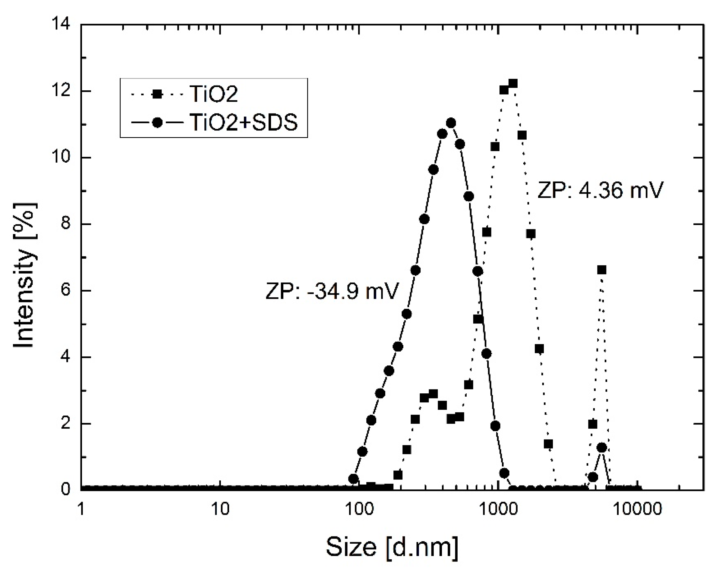
In the first approach, P25 Degussa TiO2 NPs were first chemically functionalized with anionic surfactant SDS in aqueous solution. Therefore, 1.4 g of SDS was dissolved in 200 mL of distilled water and successively 1g of TiO2 NPs was slowly added. The white suspension obtained was stirred for 6 h after the functionalized TiO2-SDS NPs were recovered by centrifugation at 6000 rpm for 10 min and finally dried overnight at 45 °C in an oven. Functionalized NPs were then mechanically dispersed by stirring (30 min) and sonication (30 min) in the amount of H2O required for the dope solution preparation.
In the second approach, the TiO2 NPs were first chemically modified as described above, which was subsequently followed by mechanical modification in the organic solvent solution. In particular, the dried chemical functionalized TiO2 NPs were then manually ground to a fine powder by using a mortar. The modified TiO2 was suspended in NMP solvent under continuous stirring until a stable dispersion was obtained. Subsequently, the amount of PEG 400 (required for the dope solution preparation) was added and the suspension was stirred for 1 h. Thereafter the suspension was sonicated using a Sonics Vibracell VCX 750 (Sonics, Newtown, CT, USA) using 40% of amplitude maintaining the temperature during sonication below 30 °C.
2.3. Nano-TiO2 Particle and Dispersion Characterization
The TiO2 particle size distribution and zeta potential of the aqueous suspensions was characterized at 25 °C using a particle size analyzer Zetasizer Nano ZS from Malvern Instruments Ltd. (Malvern, UK). The measuring principles are based on analyzing the dynamic fluctuations of light scattering intensity caused by the Brownian motion of the particles. The hydrodynamic radius, or diameter, was calculated via the Stokes-Einstein equation from the aforementioned measurements. The potential stability of the suspensions was studied by measuring the electrophoretic mobility using a zeta potential analyzer Zetasizer Nano ZS from Malvern Instruments Ltd. (Malvern, UK). The particle size distribution and electrophoretic mobility measurements were studied by using small amounts of modified and unmodified TiO2 in aqueous solutions (0.15 wt %). Moreover, a visual stability test in organic solvents was performed to determine the ability of the TiO2 nanoparticle suspensions to remain dispersed over a period of time. Photos of the suspensions prepared using the various dope compositions inside clear glass containers were captured at certain intervals.
2.4. Hollow Fibers (HFs) Preparation
The appropriate amount of solvent was heated at 80 °C in a 2 neck round bottom flask using an oil bath. The additives (PVP k17, PEG400) and polymer (PVDF 6012) were slowly added into the pre-heated solvent using mechanical stirring. The TiO
2 NPs (prepared with the two approaches described above) were then added as a water formulation (HF 1-0.5) or a PEG 400 formulation (HF 2-0.5). The compositions of dope solutions used in this study is presented in
Table 2. The HFs containing the TiO
2 produced using the first approach for dispersing the TiO
2 powder are named HF 1-0.5, while the HFs following the second approach are named HF 2-0.5. Moreover, PVDF HFs without TiO
2 were also prepared, as reference samples, and labelled as HF 1-0 and HF 2-0, respectively.
Dope solution was kept at a selected temperature overnight and then transferred to a heated tank and spun through a spinneret. The dry/wet spinning technique was used for HF fabrication, as described elsewhere [
49,
50]. The detailed conditions of fiber spinning (such as bore fluid composition and flowrate, coagulation bath composition, spinning rate) are reported in
Table 3.
The produced HFs were washed in hot water (60 °C) and then treated overnight in a sodium hypochlorite (NaClO 4 g/L) solution for PVP removal as described in previous works [
49,
50]. In order to avoid collapse of the fibers’ porous structure, they were soaked for 4 h in a glycerol aqueous solution, with concentration of 30 wt %, before drying, as already described elsewhere [
49,
50]. Before any permeability test, the glycerol was completely washed out with hot deionized water (60 °C).
2.5. Characterization of HF Membranes
2.5.1. HFs Morphology and Elemental Analyses
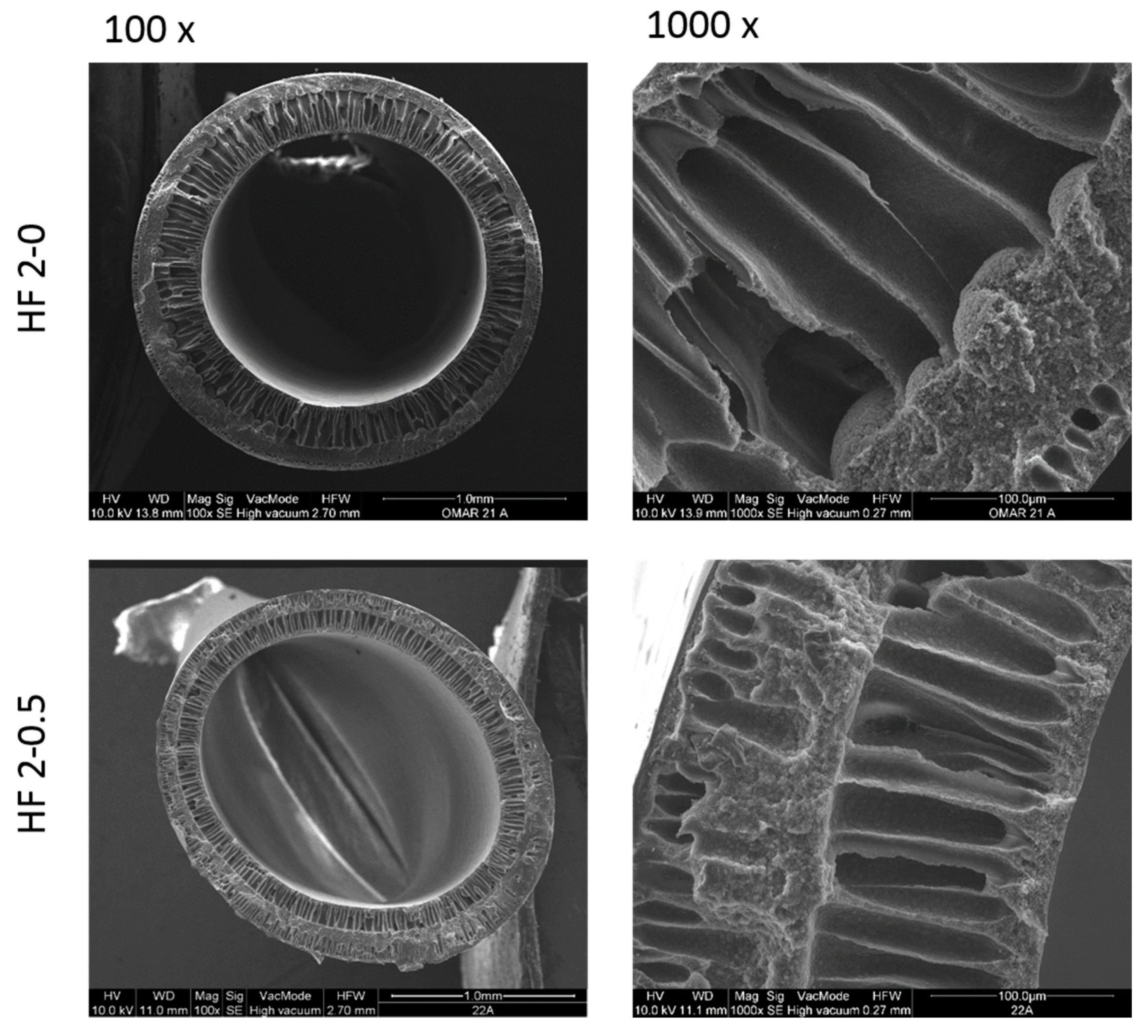
The morphology of the PVDF HFs was observed by Scanning Electron Microscopy (SEM) (Quanta FENG 200, FEI Co., Hillsboro, OR, USA). Fibers were freeze fractured using liquid nitrogen to analyze their cross-sectional morphology. A thin conductive gold layer was coated on pure PVDF HFs to improve the imaging resolution and to prevent electrical charging, while a carbon layer was coated on TiO2-doped HFs to avoid interference with the inorganic material.
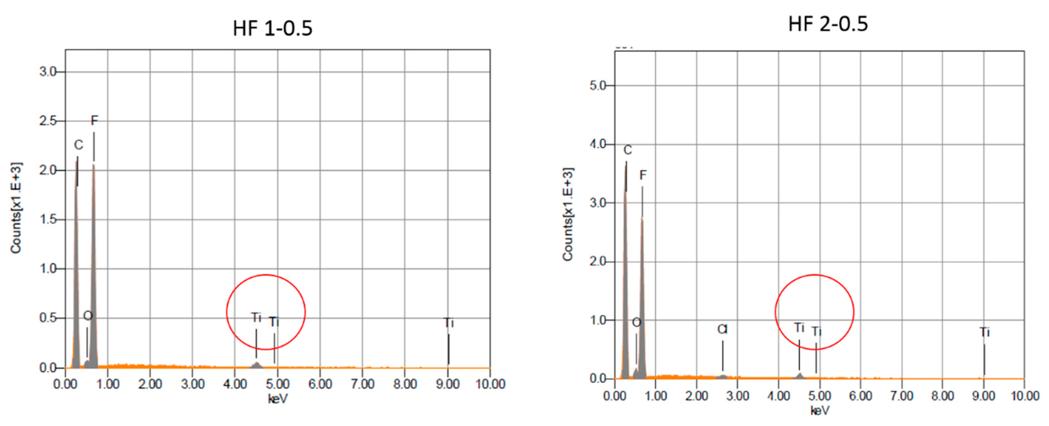
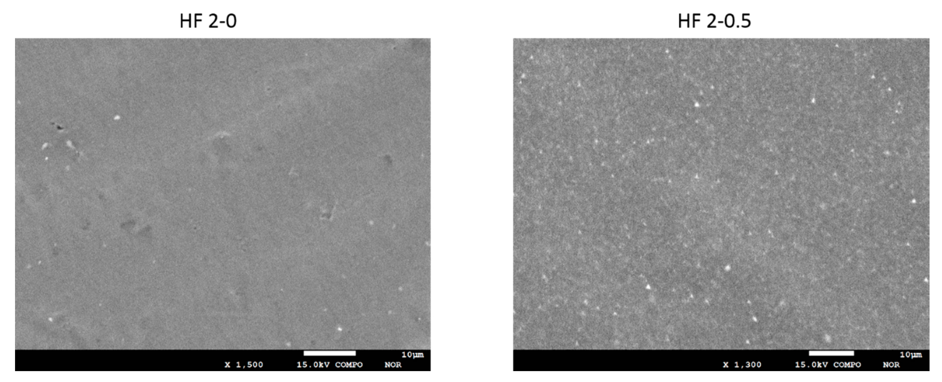
Energy-dispersive X-ray diffraction (EDX) and backscattered detector (BSD) measurements were carried out with an Electron Probe Micro Analyzer (EPMA)-JEOL-JXA 8230 (Jeon, Akishima, Japan). The samples were sputter coated with a thin layer of graphite prior the analyses (Carbon Coater QUORUM Q150T-ES).
2.5.2. HFs Porosity, Mechanical Properties and Contact Angle
Fiber porosity, ε, was measured gravimetrically, as described in literature [
49]. Fibers’ Young’s modulus and elongation at break were measured by using a ZWICK/ROELL Z 2.5 test unit as described elsewhere [
51]. Briefly, each fiber type was cut (6 cm length) and stretched unidirectionally at the constant rate of 5 mm/min at room temperature until their break. From the resulting stress/strain curve the mechanical properties of the fibers were calculated by the software. For each fiber at least five measurements were carried out and the average and standard deviation were then calculated.
Contact angle was determined by the method of the sessile drop using a CAM200 instrument (KSV Instrument LTD, Helsinki, Finland). The contact angle was determined on the outer surface of the fibers.
2.5.3. Bubble Point and Average Pore Size
Capillary flow porometer tests were carried out using the instrument, CFP 1500 AEXL (PMI porous materials Inc., Ithaca, NY, USA) for measuring the bubble point and average pore size of the fibers, as described elsewhere [
52]. Perfluoro-compound FC-40
TM (Fluorinert
TM FC-40, Sigma-Aldrich, Milano, Italy) was used as a wetting liquid and tests were performed using the wet up/dry up method [
53]. For each fiber at least three measurements were carried out and the average and the standard deviations were calculated.
2.5.4. Stability Tests of Membranes under UV-A Irradiation
Stability of produced HFs was tested by comparing the pure water fluxes with and without UV-A-irradiation. For stability tests HF 1 membranes were selected as model fibers. Ten modules of each hollow fiber membrane type (HF 1-0 and HF 1-0.5) were prepared. Each module contained three HFs. Of the defect-free modules in wetting equilibrium, five modules were kept in the dark and five modules were irradiated.
The irradiation light sources used in this study were black light PHILIPS TL-D 18 W BLB 1SL (Philips, Amsterdam, Netherlands) with λ
max at 365 nm [
54]. In order to irradiate multiple membrane modules simultaneously with one lamp, they were fixed in a lamp stand holding a maximum of 8 glass modules at a fixed distance of 12 cm to the UV-A lamp. In this setup the membranes in the modules were irradiated only from one side. For this reason, they were rotated by 90° every 60 min. UV-A intensity of 0.63 to 0.66 mW/cm
2 was recorded with a YK-35UV sensor produced by Lutron Electronic behind borosilicate glass tubes and planes of the same thickness and type as the membrane modules. Internal shadowing of the membrane fibers is neglected in the evaluation.
Pure water flux of the irradiated and non-irradiated membrane samples was determined after 1, 2.5, 5, 10, 25 and 50 h of irradiation of the complete membrane surface (with double this time spent in the irradiation stand).
2.5.5. Pure Water Permeability (PWP) Measurements
Water permeation experiments were conducted in a cross-flow filtration mode setup with lab-made glass modules containing 3 HFs (20 cm length) with a membrane area of 0.0036 m
2 each. PWP tests were performed at ambient temperature in dead-end filtration mode. Deionized water was fed from a nitrogen pressurized tank with 0.5 bar (Wika Manometer 232.50.100, range 0–1.0 bar) and the permeate weight increase was recorded over 20 min using an Ohaus Explorer
® EX6201 scale (Ohaus, Parsippany, NJ, USA) with digital output. Due to the low permeate flow rate, no back-pressure on the permeate side of the membrane could be safely assumed when characterizing polymeric membrane samples. PWP setup for measuring the cross-flow flux in an outside-in configuration was used. The details of the setup have been already reported in [
55]. For each fiber at least three measurements were carried out and the average and the standard deviations were calculated.
2.5.6. Photocatalytic Activity
For the measurement of catalytic activity MB was pre-adsorbed, in accordance to what is described in ISO 10678: 2010 [
56], by adding conditioning solution (20 μmol/L in deionized water) into the membrane module (around 4 L/m
2) and storing it in the dark for 12 h before the measurement.
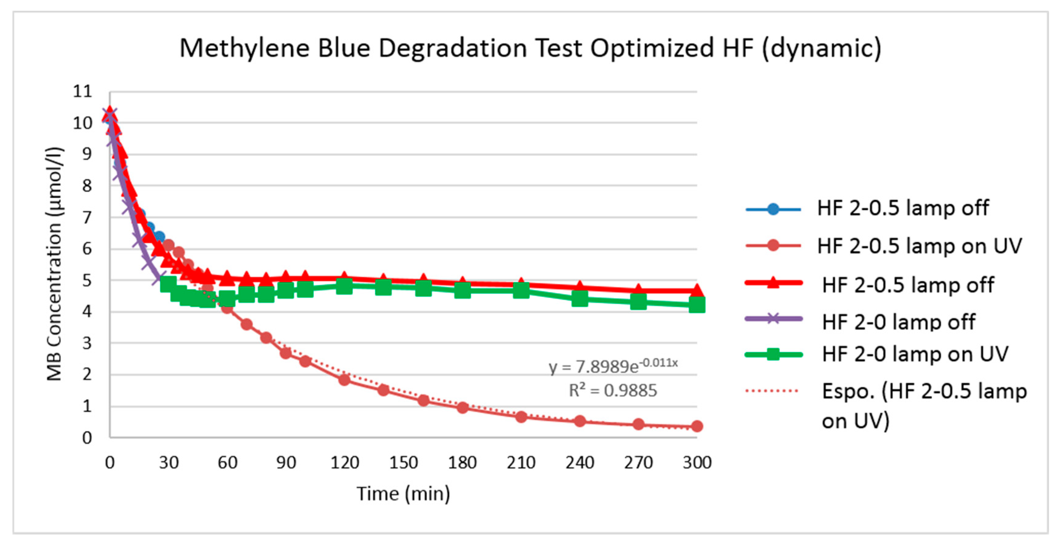
Catalytic activity was then measured by circulating 250 mL of 10 μmol/L MB solution in cross-flow mode over a single membrane module. Trans-membrane pressure (TMP) was kept at 0.5 bar and flow velocity was around 0.06 m/s. Both retentate and permeate were recirculated to the feed tank.
The membrane glass module containing three fibers of approximately 200 mm length and a membrane of 0.0036 m2 was placed in the middle of two PHILIPS TL-D 18 W BLB 1SL lamps (λmax = 365 nm). The distance of the membrane to the UV lamps was 6 cm, and the estimated light intensity at the membrane surface was 2.7 mW/cm2 taking the glass absorption into account. Irradiation was started after 30 min of recirculation. During the overall 300 min of experiment (first 30 min without irradiation and then 270 min with UV-A irradiation), 25 samples of 1 mL were taken from the feed tank and their MB concentration was immediately determined by measuring the light absorption at 664 nm.

 ,
, 


