Article

Geometrically Necessary Dislocations on Plastic Deformation of Polycrystalline TRIP Steel

1
Department of Materials Science and Metallurgical Engineering, Universitat Politècnica de Catalunya, Campus Diagonal Besòs-EEBE, Barcelona 08019, Spain
2
Centre for Research in Multiscale Engineering of Barcelona, Universitat Politècnica de Catalunya, Campus Diagonal Besòs-EEBE, Barcelona 08019, Spain
3
Department of Materials Science and Engineering, Saarland University, Saarbrucken 66123, Germany
*
Author to whom correspondence should be addressed.
Crystals 2019, 9(6), 289; https://doi.org/10.3390/cryst9060289
Submission received: 20 March 2019 / Revised: 27 May 2019 / Accepted: 30 May 2019 / Published: 3 June 2019
(This article belongs to the Special Issue Mechanical Behaviour of Austenitic Stainless Steels)

Abstract

:
In this study, the main deformation behavior in terms of geometrically necessary dislocations (GND) was investigated on a transformation induced plasticity (TRIP) stainless steel by using sharp indentation at nanometric length scale. Results evidence that austenitic grains display an isotropic behavior on terms of GND, the main deformation mechanism being the Frank–Read source activated at local level.

1. Introduction

Transformation induced plasticity (TRIP) steels present a metastable austenitic phase which transforms to martensite due to plastic deformation, either during forming or under service conditions [1]. This phase transformation acts as a reinforcing mechanism which makes those steels ideal materials to replace the conventional grades due to their excellent combination of formability, crash-absorbing capability, and good corrosion resistance [2]. The γ to α′ phase transformation is complex and the theory on martensitic transformation remains uncompleted. Numerous studies have tried to quantify the transformation and several models have been postulated to predict the mechanical behavior [3,4,5,6,7,8,9,10,11,12,13,14,15,16,17,18]. However, the lack of a profound understanding of how parameters such as chemical composition, temperature, strain rate, grain size, and deformation mode influence the transformation makes it hard to generate precise constitutive models. In this sense, it is important to understand the micromechanics of single grains, especially the dependence of mechanical properties (hardness and elastic modulus) and phase transformation with crystallographic orientation.
Several researchers have studied the mechanical properties of steels by means of nanoindentation of individual grains [19,20,21,22,23,24,25,26,27]. For example, Tromas et al. [19] reported the hardness and elastic modulus anisotropy of plasma-nitrided AISI 316L stainless steel as a function of the crystallographic structure, and Taylor et al. [20] evaluated the hardness of grains in dual phase steels. There are also a few reports on the mechanical behavior of the individual austenite grains in TRIP steels [21,22], but all of them deal with the most extended group of these steels, those with a ferritic matrix. Recently, the dependence of the local mechanical properties of the austenite phase with the crystallographic orientation has been demonstrated [23]. Results achieved for the same steel grade here studied, that is, AISI 301LN, pointed out that hardness of (001) and (101) oriented grains is lower than for (111) ones. This hardness inhomogeneity had been previously reported for others materials using the nanoindentation technique [24,25,26] and it was attributed to the presence of the geometrically necessary dislocations (GNDs) resulting from the γ → α’ transformation in the vicinity of the interface. However, in the literature this information is not available for TRIP stainless steels.
Within this context, the aim of the present work was to analyze the dislocation motion depending on the crystallographic orientation by GNDs that promote differences in plastic deformation and therefore influence the hardening behavior that these steels present at the microstructural level.

2. Experimental Procedure

The material investigated was a commercial AISI 301LN stainless steel, equivalent to grade EN 1.4318, supplied by Outokumpu (Finland) as 2 mm thick sheets (more information is available in [28]).
A homogeneous array of 400 imprints (20 by 20) was made by using a Berkovich indenter. This array was performed at 200 nm of maximum displacement into surface by using a nanoindenter XP (MTS) equipped with a continuous stiffness measurement module, the latter allowing a dynamic determination of the mechanical properties during the indentation process. A constant distance around 5 μm was held between each imprint in order to avoid any overlapping effect. Along the indentation process, the indentation strain rate was held at 0.05 s−1.
Electron backscatter diffraction (EBSD) analyses, in terms of local orientation gradients in deformed austenitic grains, were carried out using a FEI Helios NanoLab field emission scanning electron microscopy (FESEM) operated at 20 keV. EBSD analyses were performed using EDAX TSL OIM data collection system with a step size of 30 nm. The data post-processing consisted of the application of a confidence index (CI) standardization routine and the filtering of the data possessing a CI below 0.09. GNDs density is provided in terms of 10−12 m−2. This calculation was performed according the methodology proposed by Field et al. [29], whose algorithm considers both types of dislocations: Edge and screw.
Surface observation of a small region of the homogeneous indentation array, as well as the main deformation mechanisms induced near the residual imprints, were performed by atomic force microscopy (AFM), working in tapping mode. A dimension 3100 microscope from Bruker was used to carry out the different measurements. All the images were processed with the WSxM software [30].

3. Results and Discussion

The image quality (IQ) and the local crystallographic orientation map for the indentations array are shown in Figure 1a,b, respectively. Figure 1a exhibits a microstructure consisting of a monomodal austenitic equiaxial grains distribution, whose sizes are 50 ± 4 μm. Martensitic lamellas were not discerned. Figure 1b presents the corresponding local crystallographic map determined by means of EBSD, where several pre-existing twins can also be observed (indicated by white arrows).
Figure 2a shows a set of twelve overlapped AFM images (error signal mode) reconstructing part of the indentation array (marked as a white dashed rectangle in Figure 1a), where grain boundaries (GBs) are drawn (white lines). As can be observed, several slip lines can be identified around the indents due to the emergence and propagation of the (111) plane trace into the surface. Depending on the crystallographic orientation, the slip lines displayed different orientations (Figure 2b). However, no information regarding dislocations can be acquired with this technique. Therefore, in order to elucidate the dislocations movement during the indentation process, GNDs maps were obtained by using EBSD and reported considering that the minimum misorientation angle of a low-angle GB is 5 degrees.
Figure 3 exhibits the images of two different regions with several residual imprints (identified with white full line rectangles in Figure 1a, labelled as 1 and 2). GND maps are presented in the right hand side of Figure 3a,b, respectively. The plastic field produced by the nanoindentations induced lattice rotations (see black arrows) is clearly depicted in the local crystallographic maps presented in Figure 3a,b. As discussed by several authors [31,32,33,34], this phenomenon may be attributed to the activation of different slip systems due to the complex indenter geometry, causing a gradual change in the loading axis during the indentation process. On the other hand, as reported by Roa et al. [23], the (001) plane presented lower hardness than the (111). This behavior might be related to the necessary condition to increase the stress to activate dislocation sources, and successively move the dislocations, resulting in higher hardening gradients. Within this context, the GNDs map provides information about the dislocation activity for different crystallographic orientations; see right hand side in Figure 3a,b.
During a continuous indentation process with a sharp indenter, mobile unpinned dislocations in the vicinity of the GBs can interact with each other. Depending on their Burgers vector, they will either annihilate or glide to the contiguous austenitic grain and thus, depending on the crystallographic orientation, can interact with the immobile dislocations influencing the early stage strain hardening response. However, as observed in Figure 3, the amount of dislocations at the GB remained quite constant whereas the maximum dislocation concentration was located at the contact point (defined as the region between the material and the edge of the residual imprint). Furthermore, when the stress field induced during the indentation process decreased, the dislocation activity also decreased, as is evident in both GNDs map images. These observations highlight the fact that Frank–Read sources (see Figure 4) were the main deformation mechanism activated during the indentation process of these TRIP stainless steels. Moreover, it is independent of the crystallographic orientation, which leads us to conclude that the GNDs activity is isotropic.
Figure 4 presents a magnification of the GND map for an imprint performed at the GBs. Clearly, the maximum GND density was observed at the edge of the residual imprint where, as already mentioned, the induced field stress was complex. On the other hand, due to the complex stress induced at the edge of the residual imprint, the maximum amount of deformation was in the order of 7 × 10⁻¹⁰ m−2. Furthermore, the stress field induced by the Berkovich indenter produces a multiplication of dislocations by Frank–Read sources, as clearly described Hull et al. [35]. In TRIP steels, as the GND maps highlighted, some dislocations are allocated partially in their slip planes; predominantly in the maximum density (close packed) plane for the f.c.c. (face centered cubic) structures. Within this context, during the indentation process the shear stress field produces a displacement of the crystal above the slip plane relative to that below by one atom spacing b. This process is regenerative, since it can be repeated until the dislocation source reaches the surface. In other words, the shear stress, τ, exerts a force τ·b per unit length of line and tends to make the dislocation bow out. Moreover, as is evident in the GND maps, the radius of curvature, R, depends on the stress applied. Thus, as τ increases, the R of the slip line decreases and the line bows out until the minimum value.

4. Conclusions

(i)
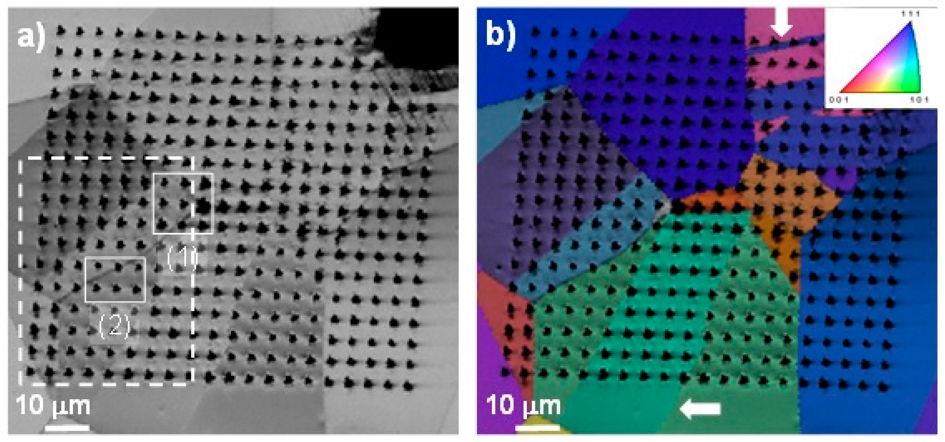
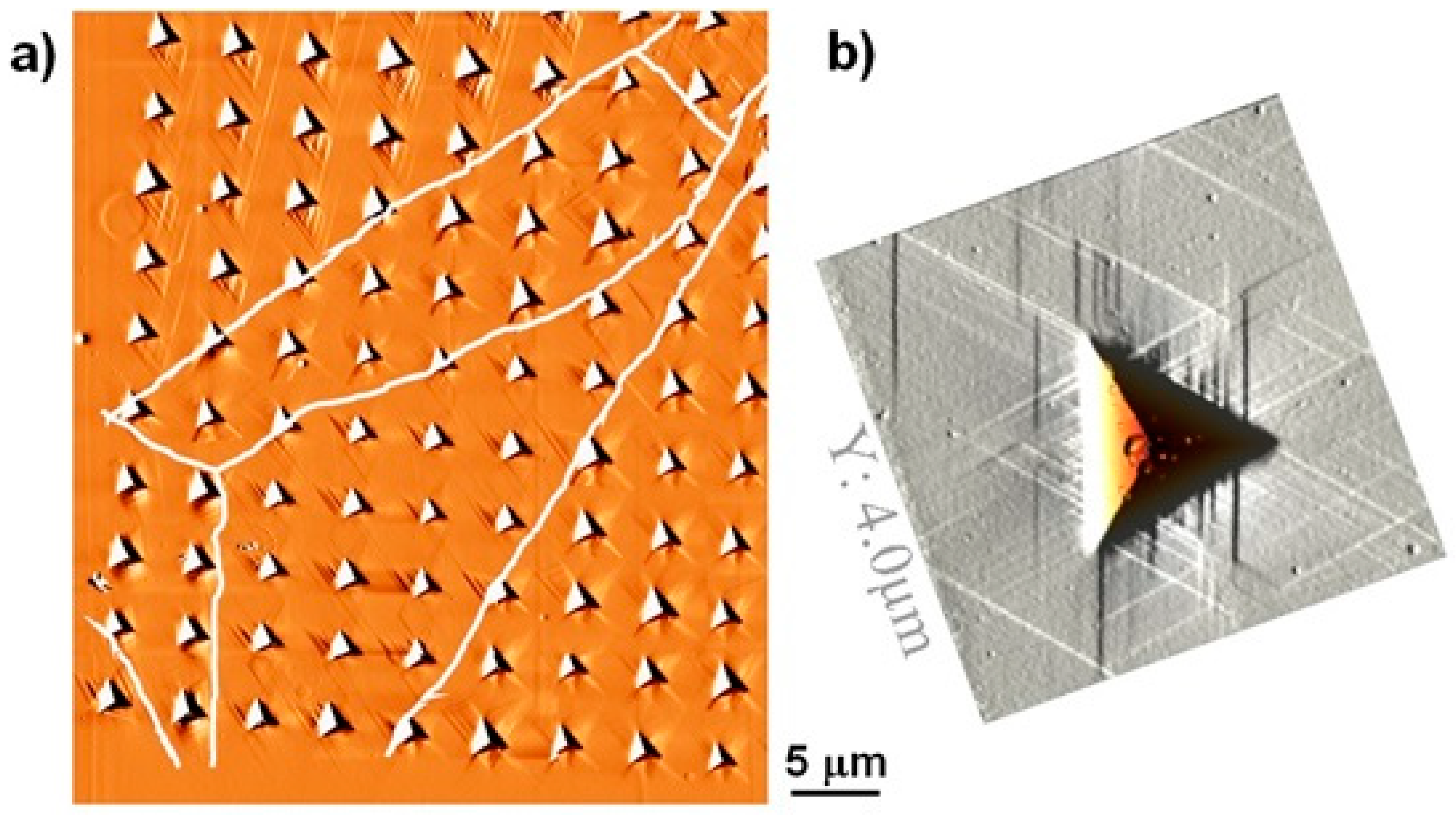
The nanomechanical tests conducted by using a sharp Berkovich indenter on individual austenitic grains led to the activation of the main deformation mechanisms. Hence, slip traces have been observed by advanced characterization techniques.
(ii)
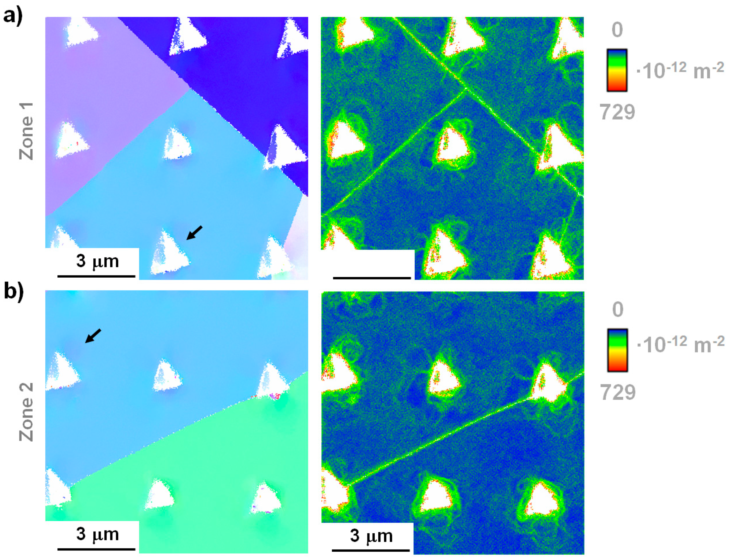
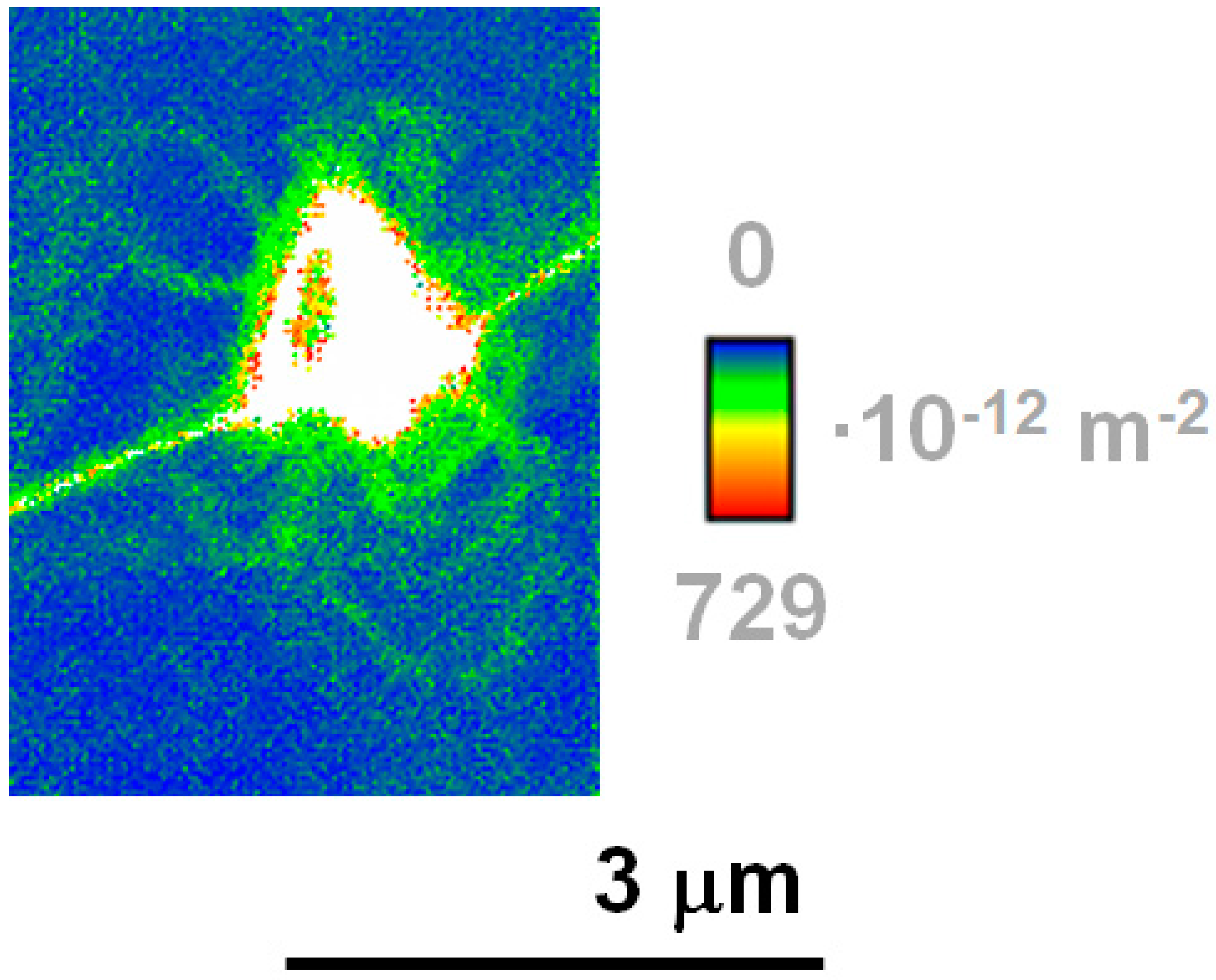
A GND map methodology provides information regarding the complex stress fields induced by nanoindentation inside certain crystallographic orientations.
(iii)
Austenitic grains display an isotropic behavior regarding the GND maps, with the Frank–Read source being the main deformation mechanism.
(iv)
All these results can serve as valuable inputs for microstructurally informed computations aimed at predicting the flow behavior at the macroscopic length scale.

Author Contributions

J.J.R., S.S. and A.G. carried out the methodology, formal analysis and validation of the results. J.J.R. carried out the original draft preparation, while G.F. and A.M. focused on review, editing and supervision.

Acknowledgments

The authors would like to acknowledge the financial support from the Spanish Government through the project MAT2015-70780-c4-3. S.S., A.G. and F.M. wish to acknowledge the EFRE Funds of the European Commission for support of activities within the AME-Lab project. This work was supported by the CREATe-Network Project, Horizon 2020 Program of the European Commission (RISE Project Nr. 644013). J.J.R. acknowledges the Serra Hunter program of the Generalitat de Catalunya.

Conflicts of Interest

The authors declare no conflict of interest.

References

  1. Vogt, J.-B.; Magnin, Z.; Foct, J. Effective stresses and microstructure in cyclically deformed 316L autenitic stainless steel: Effect of temperature and nitrogen content. Fatigue Fract. Eng. Mater. Struct. 1993, 16, 555–564. [Google Scholar] [CrossRef]
  2. Andersson, R.; Magnusson, C.; Schedin, E. Using stainless steel for energy absorbing components in automobiles. In Proceedings of the Second Global Symposium on Innovations in Materials Processing and Manufacturing: Sheet Materials, TMS Annual Meeting, New Orleans, LA, USA, 11–15 February 2001. [Google Scholar]
  3. Zandrahimi, M.; RezaBateni, M.; Poladi, A.; Szpunar, J.A. The formation of martensite during wear of AISI 304 stainless steel. Wear 2007, 263, 674–678. [Google Scholar] [CrossRef]
  4. Olso, G.B.; Cohen, M. A mechanism for strain-induced nucleation of martensitic transformations. J. Less Common Met. 1972, 28, 107–118. [Google Scholar] [CrossRef]
  5. Ludwigson, D.C.; Berger, J.A. Plastic Behavior of Metastable Austenitic Stainless steels. J. Iron Steel Inst. 1969, 207, 63–69. [Google Scholar]
  6. Fang, X.F.; Dahl, W. Strain hardening and transformation mechanism of austenitic stainless steels. Mater. Sci. Eng. A 1991, 141, 189–198. [Google Scholar] [CrossRef]
  7. Olson, G.B.; Cohen, M. Kinematics of strain-induced martensitic nucleation. Metall. Trans. A 1975, 6, 791–795. [Google Scholar] [CrossRef]
  8. Stringfellow, R.G.; Parks, D.M.; Olson, G.B. A constitutive model for transformation plasticity accompanying strain-induced martensitic transformation in metastable austenitic steels. Acta Metall. 1992, 40, 1703–1716. [Google Scholar] [CrossRef]
  9. Tomita, Y.; Iwamoto, T. Constitutive modeling of TRIP steels and its application to the improvement of mechanical properties. Int. J. Mech. Sci. 1995, 37, 1295–1305. [Google Scholar] [CrossRef]
  10. Serri, J.; Martiny, M.; Ferron, G. Finite element analysis of the effects of martensitic phase transformation in TRIP steel sheet forming. Int. J. Mech. Sci. 2005, 47, 884–901. [Google Scholar] [CrossRef]
  11. Shin, H.C.; Ha, T.K.; Chang, Y.W. Kinetics of deformation induced martensitic transformation in a 304 stainless steel. Scr. Mater. 2001, 45, 823–829. [Google Scholar] [CrossRef]
  12. Narutani, T.; Olson, G.B.; Cohen, M. Constitutive flow relations for austenitic stainless steels during strain-induced martensitic transformation. J. Phys. 1982, 43, 429–434. [Google Scholar]
  13. Cortés, J.A.; Tsuta, T.; Mitani, Y.; Osakada, K. Flow stress and phase transformation analysis in the austenitic stainless Steel under cold working—Part 1: Phase transformation characteristics and constitutive formulation by energetic criterion. JSME Int. J. 1992, 35, 201–209. [Google Scholar]
  14. Tsuta, T.; Cortés, J.A. Flow Stress and Phase Transformation Analyses in Austenitic Stainless Steel under Cold Working. Part 2, Incremental Theory under Multiaxial Stress State by the Finite-Element Method. JSME Int. J. 1993, 36, 63–72. [Google Scholar] [CrossRef]
  15. Levitas, V. Thermomechanical theory of martensitic phase transformations in inelastic materials. Int. J. Solids Struct. 1998, 35, 889–940. [Google Scholar] [CrossRef]
  16. Levitas, V.; Idesman, A.V.; Olson, G.B. Continuum modeling of strain-induced martensitic transformation of shear-band intereactions. Acta Mater. 1999, 47, 219–233. [Google Scholar] [CrossRef]
  17. Kubler, R.; Berveiller, M.; Cherkaoui, M.; Inal, K. Transformation textures in unstable austenitic steel. Trans. ASME 2003, 125, 12–17. [Google Scholar] [CrossRef]
  18. Garion, C.; Skoczen, M.; Sgobba, S. Constitutive modelling and identification of parameters of the plastic strain-induced martensitic transformation in 316L stainless steel at cryogenic temperatures. Int. J. Plast. 2006, 22, 1234–1264. [Google Scholar] [CrossRef]
  19. Tromas, C.; Stinville, J.C.; Templier, C.; Villechaise, P. Hardness and elastic modulus gradients in plasma-nitrided 316L polycrystalline stainless steel investigated by nanoindentation tomography. Acta Mater. 2012, 60, 1965–1973. [Google Scholar] [CrossRef]
  20. Taylor, M.D.; Choi, K.S.; Sun, X.; Matlock, D.K.; Packard, C.E.; Xu, L.; Barlat, F. Correlations between nanoindentation hardness and macroscopic mechanical properties in DP 980 steels. Mater. Sci. Eng. A 2014, 597, 431–439. [Google Scholar] [CrossRef]
  21. Furnémont, Q.; Kempf, M.; Jacques, P.J.; Göken, M.; Delannay, F. On the measurement of the nanohardness of the constitutive phases of TRIP-assisted multiphase steels. Mater. Sci. Eng. A 2002, 328, 26–32. [Google Scholar]
  22. Tjahjanto, D.; Turteltaub, S.; Suiker, A.; van der Zwaag, S. A Micromechanical Study of the Deformation Behavior of TRIP-Assisted Multiphase Steels as a Function of the Microstructural Parameters of the Retained Austenite. Adv. Eng. Mater. 2009, 11, 153–157. [Google Scholar] [CrossRef]
  23. Roa, J.J.; Fargas, G.; Mateo, A.; Jiménez-Piqué, E. Dependence of nanoindentation hardness with crystallographic orientation of austenite grains in metastable stainless steels. Mater. Sci. Eng. A 2015, 645, 188–195. [Google Scholar] [CrossRef]
  24. Kadkhodapour, J.; Schmauder, S.; Raabe, D.; Ziaei-Rad, S.; Weber, U.; Calcagnotto, M. Experimental and numerical study on geometrically necessary dislocations and non-homogeneous mechanical properties of the ferrite phase in dual phase steels. Acta Mater. 2011, 59, 4387–4394. [Google Scholar] [CrossRef]
  25. Sun, X.; Choi, K.S.; Soulami, A.; Liu, W.N.; Khaleel, M.A. On key factors influencing ductile fractures of dual phase (DP) steels. Mater. Sci. Eng. A 2009, 526, 140–149. [Google Scholar] [CrossRef]
  26. Roa, J.J.; Fargas, G.; Jiménez-Piqué, E.; Mateo, A. Deformation mechanisms under high cycle fatigue tests in a metastable austenitic stainless steel. Mater. Sci. Eng. A 2014, 597, 232–236. [Google Scholar] [CrossRef]
  27. Sapezanskaia, I.; Roa, J.J.; Fargas, G.; Turon-Viñas, M.; Trifonov, T.; Njiwa, R.K.; Redjaïmia, A.; Mateo, A. Deformation mechanisms induced by nanoindentation tests on a metastable austenitic stainless steel: A FIB/SIM investigation. Mater. Charact. 2017, 131, 253–260. [Google Scholar] [CrossRef]
  28. Roa, J.J.; Wheeler, J.M.; Trifonov, T.; Fargas, G.; Mateo, A.; Michler, J.; Jiménez-Piqué, E. Deformation of polycrystalline TRIP stainless steel micropillars. Mater. Sci. Eng. A 2015, 647, 51–57. [Google Scholar] [CrossRef]
  29. Field, D.P.; Trivedi, P.B.; Wright, S.I.; Kumar, M. Analysis of local orientation gradients in deformed single crystals. Ultramicroscopy 2005, 103, 33–39. [Google Scholar] [CrossRef] [PubMed]
  30. Horcas, I.; Fernández, R.; Gómez-Rodríguez, J.M.; Colchero, J.; Gómez-Herrero, J.; Baro, A.M. WSXM: A software for scanning probe microscopy and a tool for nanotechnology. Rev. Sci. Instrum. 2007, 78, 013705. [Google Scholar] [CrossRef] [PubMed]
  31. Lloyd, S.J.; Castellero, A.; Giuliani, F.; Long, Y.; McLaughlin, K.K.; Molina-Aldareguia, J.M.; Stelmashenko, N.A.; Vandeperre, L.J.; Clegg, W.J. Observations of nanoindents via cross-sectional transmission electron microscopy: A survey of deformation mechanisms. Proc. R. Soc. A Math. Phys. Eng. Sci. 2005, 461, 2521–2543. [Google Scholar] [CrossRef]
  32. Zaafarani, N.; Raabe, D.; Singh, R.N.; Roters, F.; Zaefferer, S. Three-dimensional investigation of the texture and microstructure below a nanoindent in a Cu single crystal using 3D EBSD and crystal plasticity finite element simulations. Acta Mater. 2006, 54, 1863–1876. [Google Scholar] [CrossRef]
  33. Brown, L.M. Slip circle constructions for inhomogeneous rotational flow. Mater. Sci. Forum 2007, 550, 105–117. [Google Scholar] [CrossRef]
  34. Zaafarani, N.; Raabe, D.; Roters, F.; Zaefferer, S. On the origin of deformation-induced rotation patterns below nanoindents. Acta Mater. 2008, 56, 31–42. [Google Scholar] [CrossRef] [Green Version]
  35. Hull, D.; Bacon, D.J. Introduction to Dislocations, 4th ed.; Elsevier Ltd.: New York, NY, USA, 2001. [Google Scholar]
Figure 1. (a) Image quality (IQ) and (b) local crystallographic orientation map of an indentation array of 400 imprints (20 by 20) done at a maximum displacement into surface of around 200 nm. White arrows in Figure 1b show the pre-existing twins.
Crystals 09 00289 g001
Figure 2. (a) Set of twelve overlapped atomic force microscopy (AFM) images (error signal mode) exhibiting the main plastic deformation mechanisms around the residual imprints. (b) AFM image of one indentation.
Crystals 09 00289 g002
Figure 3. The local crystallographic orientation (left hand side) and the geometrically necessary dislocations (GNDs) map (right hand side), for both regions of interest labelled in Figure 1a, observed in more detail ((a,b), respectively).
Crystals 09 00289 g003
Figure 4. GND map of a residual imprint performed at 200 nm of maximum displacement into surface showing the dislocation map induced during the indentation process.
Crystals 09 00289 g004

