Article

Symmetric Fluoroborate and its Boron Modification: Crystal and Electronic Structures

by
Błażej Dziuk
1,2,
Borys Ośmiałowski
3,
Bartosz Zarychta
1,
Krzysztof Ejsmont
1 and
Lilianna Chęcińska
4,*
1
Faculty of Chemistry, Opole University, Oleska 48, 45-052 Opole, Poland
2
Faculty of Chemistry, Wrocław University of Science and Technology, Wybrzeże Wyspiańskiego 27, 50-370 Wrocław, Poland
3
Faculty of Chemistry, Nicolaus Copernicus University, Gagarina 7, 87-100 Toruń, Poland
4
Faculty of Chemistry, University of Lodz, Pomorska 163/165, 90-236 Łódź, Poland
*
Author to whom correspondence should be addressed.
Crystals 2019, 9(12), 662; https://doi.org/10.3390/cryst9120662
Submission received: 18 November 2019 / Revised: 3 December 2019 / Accepted: 5 December 2019 / Published: 9 December 2019

Abstract

:
Four boron-carrying molecules were synthesized and purified. These were found to be (a) relatively neutral with respect to the parent BF derivative and (b) functionalized by donor–acceptor groups resulting in a charge transfer within the molecule. The study discusses the steric effect and the influence of the substitution of the side rings on the surroundings of the boron atom. Electronic structures were characterized by real-space bonding indicators. Hirshfeld surface and energy frameworks tools were applied to examine the crystal packing features.

Graphical Abstract

1. Introduction

The rigid, organic compounds carrying the BF2 group are often fluorophores characterized by bright fluorescence and excellent photostability [1,2]; however, their most representative examples are BODIPY dyes, which are characterized by small Stokes shift values. Their most characteristic structural feature is the substitution of the acidic proton present in their precursors by a BF2 group, thanks to which a boron moiety can be easily inserted, and the compounds are highly fluorescent. However, such acidic proton is not only present in NH-carrying compounds but also in CH acids [3,4,5,6,7,8,9] and OH-carrying molecules [10,11,12,13], resulting in the formation of, for example, an NBF2O pattern instead of NBF2N one, as in BODIPYs. The spectral features of difluoroborates may be tuned by a variety of methods, such as the substituent effect [8,14], benzannulation [7], or elongation of the conjugation path [15]. Another is the modification of the boron Lewis acidity center; however, the BF2 group is generally less reactive than, for example, BCl2 [16,17]. Still, it is possible to exchange fluorine by a methyl group in BODIPYs, but the reactivity of the boron atom should be enhanced by the presence of the electronegative groups in the BODIPY core [18]. It is important to stress that BODIPY dyes, although very useful and with tunable properties, are not the only ones that contain a BF2 group: a review of non-BODIPY dyes by Ziessel et al. [13] presents and discusses various other dyes with NBF2N, NBF2O, and OBF2O patterns. However, at that time, there was a limited number of publications related to amide-based boron-carrying molecules compared to those where the substrate was phenol or amine.
There is a constant need to develop new materials by the functionalization of known compounds. In general, the boron atom [17,19] may be functionalized by reacting the BF2 group with, for example, AlCl3 [20] or Et2BCl [21,22], and then with another molecule to substitute chlorine. In this way, a number of BODIPY dyes substituted with O, C, and N-terminal groups attached to the boron atom can be obtained, inter alia (a) O-BODIPYs [23,24,25,26,27,28], C-BODIPYs [17,19,28,29,30,31,32], and N-BODIPYs [33,34]. A relatively small number of publications have described the reactions guided at the boron (BX) moiety with the aim of obtaining fluorescent molecules functionalized at that atom while also carrying a tridendate ligand characterized by a variable arrangement of electronegative atoms such as N,N,N-, N,O,O-, or O,N,O-, and others. This type of molecule is obtained by a two-step reaction [35] with boronic acid as the source of the boron atom. An alternative way to obtain an N,N,N-pattern to bind the boron atom, as used in subporphyrines, is to introduce a chloro/bromo derivative (BCl/BBr) and react it with the nucleophile [36]. It is worth mentioning that the tridendate ligand comprises three electronegative atoms in its core. This fact can be used to tune the properties of charge-transfer molecules by functionalization of donor and acceptor.
The way to functionalize BODIPYs and related molecules at the boron atom is the reaction of the BF2 center with AlCl3, and then with the species reacting, with resulting BCl2 mid-product [20,37]. In addition, the reaction of the BF2 group with BCl3 and then with an alkoxy anion to substitute the Cl atom by an OR moiety can be carried out [38].
The proper substitution of the fluorophore may enhance the properties suitable for two-photon absorption (TPA) [39], giving molecules that can be used for bioimaging [40]. It is worth noting that such functionalization of molecules should be relatively easy; in addition, the high TPA cross-section values and photostability should also be achieved. The TPA cross-section value can be increased by the introduction of electron-donating and electron-accepting groups in the structure. On the other hand, regarding the stability of such compounds, correct isolation of the reactive part of the molecule from interactions with the surroundings is crucial. Since these properties (TPA cross-section and reactivity) are dependent on the geometry of the molecule, accurate knowledge about the spatial arrangement of the groups is required for effective and correct molecular design. Moreover, steric hindrance allows the intermolecular interactions in fluorescent solids to be controlled [41], giving materials suitable for electronic applications [42]. However, the molecular design has some limits. One is that the reactive center must be accessible to the needed reaction during synthesis. In some BF2-carrying molecules, the difluoroborate group is close to a ring or group that hinders the reaction by exerting steric effects: although such steric effects might be needed to ensure the stability of the final product, they also may hinder effective synthesis. One of the most convenient ways to allow nucleophilic attack on the boron atom is to use the relatively flat structure of the tridentate ONO ligand [43] of monohalogenoborate, as has been demonstrated for N,N,N-ligands such as B-substituted subporphyrines [44,45,46]. So far, only one single-crystal structure of the tridendante ONO ligand, functionalized at the boron atom, has been described [47].
Hence, the aim of the current work is (a) to determine the effect of a substitution of the fluorine atom by phenyl or a phenylene-carrying electron-donating group at the boron atom and (b) identify the donor–acceptor charge transfer and its influence on the central, B-containing moiety. For such purpose, 2,6-bis(benzoylamino)pyridines were synthesized and functionalized with BF [27], BC6H5, or BC6H4-4-NMe2 groups. Compounds substituted at the boron atom were prepared by the reaction of BCl precursors obtained from 2,6-bis(benzoylamino)pyridines, using Grignard reagents. It is important to note that substrate → BCl → B-R substitution is the first example of a one-pot, two-step reaction leading to the B-substituted compounds. In previous publications, the synthesis was performed in the following order: substrate → BF2 → BCl2 → B(OR)2 [21,48,49]. The present protocol omits one step, i.e., the synthesis of the fluoroborate derivative and its purification.
Since the charge transfer has a key influence on the properties of the donor–acceptor molecules, including the value of the TPA cross-section [39], the donating group was introduced in two different positions to induce distant charge transfer (in 2, vide infra) or short-path charge transfer (in 4).
To gain a deeper insight into the electronic structures of the four compounds presented here, the study employs real-space bonding indicators (RSBI) in an approach combining Quantum Theory of Atoms in Molecules (QTAIM) [50] and Electron Localizability Indicator (ELI-D) [51,52]. In turn, to analyze the arrangement of the studied molecules in crystals, Hirshfeld surface analysis [53] was applied with quantitative support derived from pairwise interaction energies [54] and their energy frameworks [55].

2. Materials and Methods

2.1. Synthesis

The general procedure for synthesis was as follows: (a) synthesis of the 2,6-bis(benzoylamino)pyridine (1) derivative or (b) 2-N-(pentafluorobezoylaminno)-6-N- (4-dimethylaminobenzoyl)-pyridine (2). Compound 2 has been obtained in a two-step reaction: a reaction of 2,6-diaminopyridine with 4-(dimethylamino)benzoyl chloride yielding 2-(4-dimethylaminobenzoyl)-6-amino-pyridine, which was then transformed into 2 by reaction with pentafluorobenzoyl chloride. Both 1 and 2 were treated with BF3 etherate in boiling toluene (24 h at boiling point) as before [15,43]. Compounds 3 and 4 were obtained by a one-pot, two-step reaction of 2,6-bis(benzoylamino)pyridine with BCl3 (solution in DCM) in dry THF and two equivalents of DIEA. The reaction mixture was stirred at 50 °C for 5 h. Then, phenyl magnesium bromide or 4-(N,N-dimethyl)aniline magnesium bromide solution was added (two molar excess) during one hour at room temperature and the mixtures was stirred overnight; water (1–2 mL) was added, and the THF evaporated. The residues were treated with water (20–30 mL) and extracted with chloroform. All compounds were purified by flash chromatography (SiO2) with the use of DCM (1, 3), ethyl acetate (4), and acetonitrile (2) as eluent.

2.2. X-ray Single-Crystal Diffraction

The single-crystal X-ray diffraction experiments were performed at 100.0(1) K on an Xcalibur diffractometer (Rigaku Oxford Diffraction, Sevenoaks, Kent, UK), equipped with a CCD detector and a graphite monochromator (Rigaku Oxford Diffraction) with MoKα radiation and furnished with an Oxford Cryosystem N2 gas stream device. The reciprocal space was explored by ω scans. The reflections were measured with a radiation exposure time from 4 to 25 s, according to diffraction intensities. The detector was positioned at a 60-mm distance from the crystal. Procession of the diffraction data was performed using the CrysAlis CCD [56]. The structures were solved and refined by a full-matrix least-squares method using the SHELXL14 program [57]. Lorentz and polarization corrections were applied. Non-hydrogen atoms were refined anisotropically. In structures, H atoms were refined using a riding model. The structure drawings were prepared using the SHELXTL [58].
Crystal data for 1 (M = 345.13 g/mol): monoclinic, space group P21/n (no. 14), a = 11.4202(7) Å, b = 11.1659(6) Å, c = 12.5775(7) Å, β = 101.550(5)°, V = 1571.37(16) Å3, Z = 4, T = 100.0(1) K, μ(MoKα) = 0.10 mm−1, Dcalc = 1.459 g/cm3, 10452 reflections measured (3.2° ≤ Θ ≤ 26.0°), 3086 unique (Rint = 0.035), which were used in all calculations. The final R1 was 0.035 [I > 2σ(I)] and wR2 was 0.078 (all data).
Crystal data for 2 (M = 478.16 g/mol): monoclinic, space group P21/n (no. 14), a = 15.5793(10) Å, b = 7.0596(4) Å, c = 18.7116(13) Å, β = 109.925(7)°, V = 1934.8(2) Å3, Z = 4, T = 100.0(1) K, μ(MoKα) = 0.15 mm−1, Dcalc = 1.642 g/cm3, 12675 reflections measured (3.1° ≤ Θ ≤ 26.0°), 3800 unique (Rint = 0.066), which were used in all calculations. The final R1 was 0.046 [I > 2σ(I)] and the wR2 was 0.092 (all data).
Crystal data for 3 (M = 403.23 g/mol): orthorhombic, space group Cmc21 (no. 36), a = 21.2777(10) Å, b = 11.8774(5) Å, c = 7.6131(3) Å, V = 1924.0(14) Å3, Z = 4, T = 100.0(1) K, μ(MoKα) = 0.09 mm−1, Dcalc = 1.392 g/cm3, 6440 reflections measured (3.3° ≤ Θ ≤ 26.0°), 1839 unique (Rint = 0.015), which were used in all calculations. The final R1 was 0.028 [I > 2σ(I)] and the wR2 was 0.073 (all data).
Crystal data for 4 (M = 446.30 g/mol): monoclinic, space group P21/n (no. 14), a = 15.2995(6) Å, b = 8.6166(3) Å, c = 17.7823(7) Å, β = 108.625(3)°, V = 2221.46(15) Å3, Z = 4, T = 100.0(1) K, μ(MoKα) = 0.09 mm−1, Dcalc = 1.334 g/cm3, 14516 reflections measured (3.2° ≤ Θ ≤ 26.0°), 4356 unique (Rint = 0.067) which were used in all calculations. The final R1 was 0.045 [I > 2σ(I)] and the wR2 was 0.090 (all data).
The crystallographic data for compounds 14 have been deposited at the Cambridge Crystallographic Data Centre as supplementary publication no. CCDC 1572930-1572933. These data can be obtained free of charge via http://www.ccdc.cam.ac.uk/conts/retrieving.html or from the Cambridge Crystallographic Data Centre, 12 Union Road, Cambridge CB2 1EZ, UK; fax: 144 1223 336 033; email: [email protected].

2.3. Theoretical Calculations

DFT (Density Functional Theory) gas-phase geometry optimizations of 14 at the B3LYP/6-311+G(2d,2p) level of theory were carried out using Gaussian09 [59] at the starting from the atomic coordinates of the X-ray single-crystal structures. The wavefunctions files were used for a topological analysis of the electron density with AIMAll [60], whereas ELI-D descriptors were derived and analyzed with DGRID-4.6 [61].

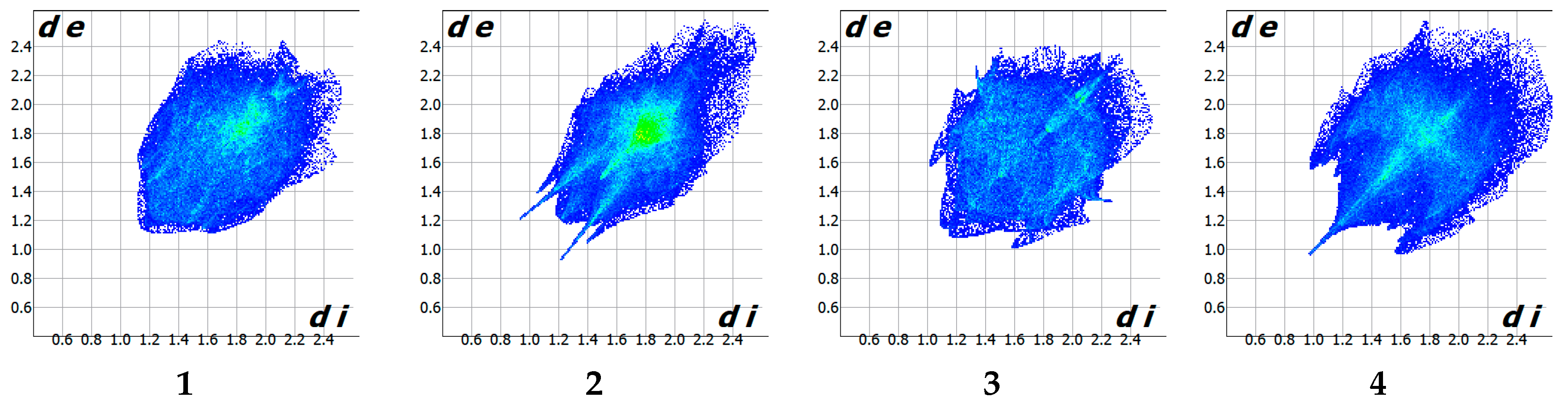
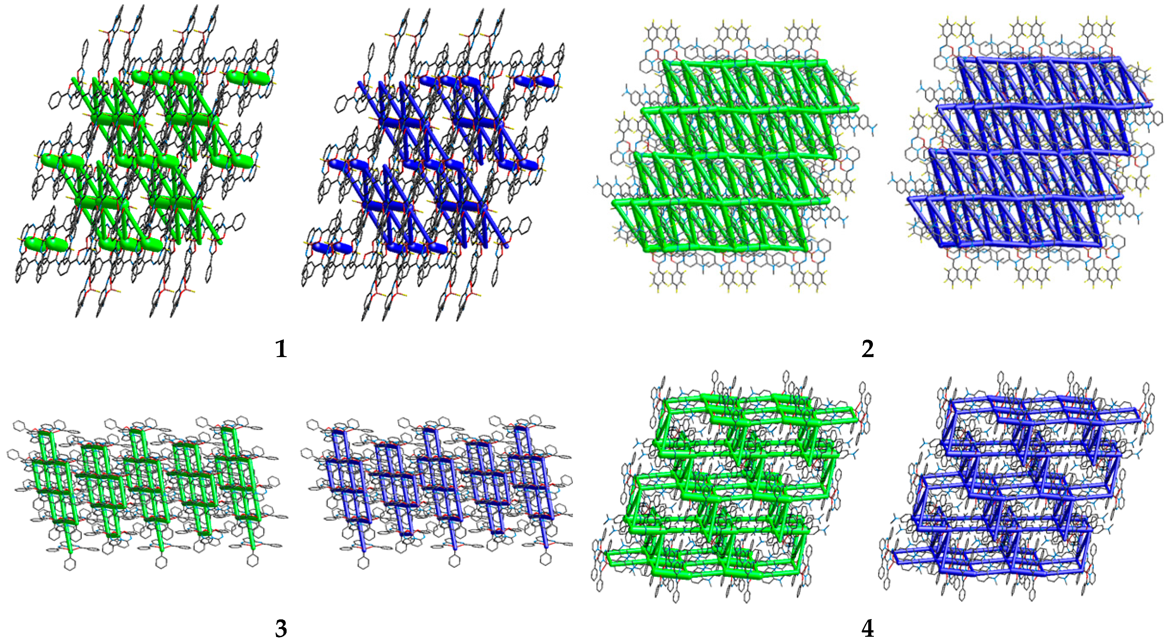
2.4. Hishfeld Surface Analysis; Pairwise Energies and their Energy Frameworks

Hishfeld surface analysis, a calculation of pairwise model energies, and a visualization of their energy frameworks, were performed using CrystalExplorer17 [62,63] software. Pairwise model energies were estimated between molecules within a standard cluster of a radius of 3.8Å at the B3LYP/6-31G(d,p) level of theory (CE-B3LYP model). In this model, the total interaction energy between any nearest-neighbor molecular pairs is given in terms of four components: electrostatic, polarization, dispersion, and exchange–repulsion, with scale factors of 1.057, 0.740, 0.871, and 0.618, respectively.

3. Results and Discussions

The compounds synthesized in this work were chosen for the reasons given in the Introduction. The symmetric fluoroborate of 1 is regarded as a reference compound. In compound 2, the polar center of the molecule, acting as an electron acceptor, is supported by the electronegative C6F5 moiety, which is a group that has previously been used in a series of two-photon absorbing compounds [64]. In addition, the phenyl substituent on the opposite side is functionalized by an –NMe2 group, which is also often used in the modification of BODIPYs [65]. To identify such donor–acceptor changes, the present study examines both the electronic structure of the single molecules and the packing features of the crystal structures. It also examines the effects of modifying the boron center by the replacement of the F→phenyl group in 3 and its donor functionalization by 4-NMe2 in 4.
Crystals 09 00662 i001

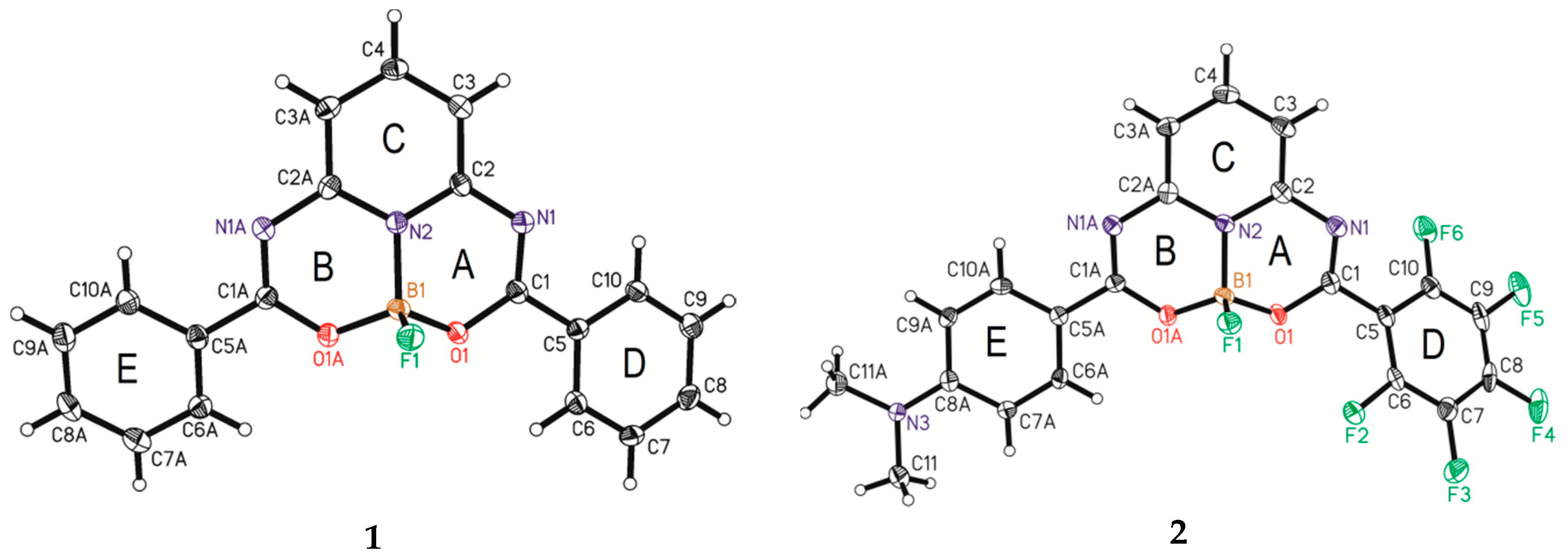
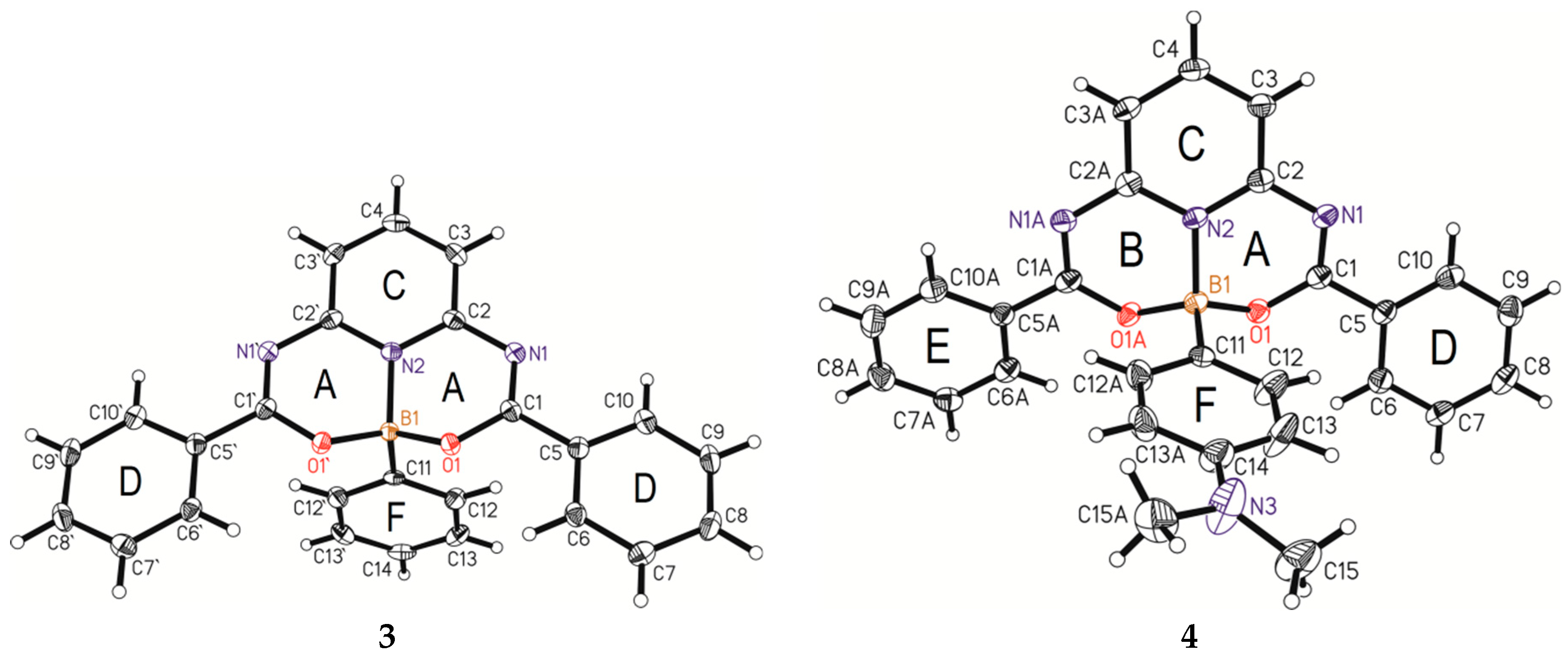
3.1. X-ray Single-Crystal Analysis

The molecular structures of boron compounds 14 are presented in Figure 1 with the atom- numbering scheme. Selected geometric parameters are collected in Table S1 (Supplementary Material). Although the crystal structure of compound 1 has been reported earlier at 223 K [43], we decided to use our data, measured at 100 K, for more consistent comparison between all four investigated structures.
In all studied compounds, the central boron atom has a tetrahedral geometry, irrespective of substituents: fluorine atom, phenyl group, and the 4-(dimethylamino)phenyl group. The respective sums of the two N−B−O angles and the O−B−O angle for compounds 14 are 326.5(1)°, 326.9(2)°, 320.0(2)°, and 319.4(1)°, which are comparable with similar structures given by Glotzbach [43]. Compounds 3 and 4 are characterized by more pronounced distortion of the tetrahedron, with the valence angles varying from 105° (O1−B1−N2) to 112° (C1−B1−N2).
The boron atom belongs to two six-membered heterocyclic rings (A and B symbols), which are both condensed with a benzene ring to form a tricyclic core skeleton. Based on the puckering [66] and asymmetry [67] parameters, the conformation of the heterocyclic rings can be described as generally intermediate between an envelope (E) and a screw boat (S), for which the (pseudo)mirror plane passing through the B1 atom and (pseudo)twofold axis passing through the B1−O1/B1−O1A bond are characteristic symmetry elements (Table S2 in Supplementary Material). The nitrogen atom (N2), in the middle of the tricyclic core skeleton, deviates by 0.150(2) Å to 0.192(2) Å from the best plane formed by the 12 surrounding atoms toward the most protruding B atom, being 0.442(3) to 0.487(3) Å away from the best plane. The deviations demonstrated by the nitrogen and boron atoms correspond well with those found for their corresponding atoms in the structure of 1,6-bis(2-hydroxyphenyl)pyridine boron bis(4-N-butyl-phenyl)phenyleneamine [47].
The heterocyclic rings are substituted by phenyl groups at the C1 and C1A atoms. The molecular conformation can be described by the mutual arrangement of planar fragments. The dihedral angle between the best least-squares planes of central benzene (N2/C2/C3/C3A/C2A, C-symbol) and phenyl (C5-C10 and C5A-C10A, D and E symbols) groups are 7.3(1)° and 20.7(1)° for compound 1, 33.0(1)°, 3.6(1)° for 2, 13.9(1)° for 3, and 2.3(1)° and 21.2(1)° for 4. Compounds 3 and 4 display another phenyl group (F symbol) substituted to the boron atom, which forms an angle of 73.4(1)° and 75.8(1)°, respectively, with the central benzene ring.

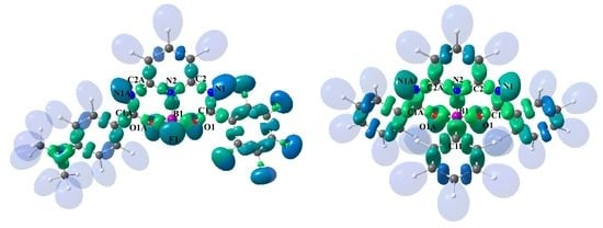
3.2. Theoretical Electron-Density Analysis

The electronic structures of the studied compounds (14) were studied using so-called real-space bonding indicators (RSBIs). These are various topological and integrated descriptors derived based on the Quantum Theory of Atoms in Molecules (QTAIM) [50] and the Electron Localizability Indicator (ELI-D) [51,52] space-partitioning schemes based on electron and pair densities, respectively. These concepts yield reliable atomic and bonding properties that complement each other. Interestingly, by using a combination of the two approaches, it is possible to determine the polarity of any bond. The Raub–Jansen index (RJI) [68,69] is calculated by overlapping ELI-D bonding basins with AIM atomic basins, and then integrating the electron populations: RJI equals 50% for homopolar bonds, and this value increases with increasing bond polarity. A set of real-space bonding indicators is collected for compounds 14 in Table 1. Isosurface representations of the ELI-D of 2 and 3 are displayed in Figure 2a,b.
Since the optimized gas-phase structure geometries correspond quite well with those obtained by X-ray single-crystal diffraction studies (Table S1 in Supplementary Material), the RSBI analysis reflects the experimentally determined trends.
All of the analyzed structures (14) contain two fused boron-containing rings differentiated by two types of structural modification: the first at the boron atom (F versus C) and the second related to charge transfer properties (introduction of donor and acceptor groups). Finally, while three molecular structures—1, 3 and 4—are nearly symmetrical, structure 2 exhibits asymmetry due to structural modifications. The N–B bonds show very similar behavior in all studied structures. The topological parameters, such as the electron density and its Laplacian at the bond critical point (bcp), appear to be dependent on bond length, as expected. Their polarity (RJI) is the highest observed for the analyzed structures (94%), suggesting that the N–B interactions have a polar-dative character [70]. The bond ellipticity [71] and the delocalization index [72,73] are slightly higher in 34 than 12. Similar trends were found for the model structures due to the stepwise substitution of the fluorine atoms by hydrogen atoms at the boron center [70]. Herein, it applies to the fluorine atom versus carbon atom.
As has been noted previously, the O–B bond in the N–B–O moiety is more sensitive to changes in the substitution pattern of the boron atom [70]. Accordingly, some differences can be seen between the topological and integrated properties of the O–B bond, especially for structure 2 (Table 1). We would like to stress that the differentiation of the O–B bonds in 2 is accompanied by changes in the O–C and N–C interactions; however, the N2–C bonds remain equal to each other. Accordingly, the distances of O1A–B and N1A–C2A are shortened following the introduction of the N,N-dimethylamine group, while O1A–C1A and N1A–C1A are lengthened. The electronegative group (–C6F5) has the opposite influence on the corresponding boron ring on the other side of the molecule. It is worth mentioning that while N1–C1 is the shortest observed bond, N1–C2 is the longest. Regarding the geometrical aspects of the considered N–C bonds, the ELI-D basin of the shortest N1–C1 bond has the greatest volume (6 Å3) and population (2.81 e), while that of the longest N1–C2 bond is characterized by the smallest ELI-D volume (2.63 Å3) and population (2.09 e).
This is the first example of the characterization of the C–B bond in borates by RSBIs using analogs of BODIPYs. In both analyzed structures with the C–B interaction (34), the carbon atom belongs to the phenyl group. The optimized bond lengths are ca. 1.6 Å. The C–B bond is characterized by the highest electron density at bcp. In addition, its Laplacian value is negative, indicating covalent interaction. Its covalent and ionic contributions are also described by the highest H/ρbcp value and the smallest G/ρbcp value [74], respectively, compared to the other studied B–X (X = N,O,F) interactions. In addition, the rather high Raub–Jansen index (82.9%) and the delocalization index (0.46) highlight the polar character. Since the bond descriptors are very similar for 3 and 4, it seems that the donor-functionalized phenyl group attached to the boron B1 atom has a negligible impact on the characteristics of the C–B bond.
Structure 2 displays more effective charge transfer than 4, which is attributed to the presence of the N,N-dimethylamine group, despite the different relative distance between the NMe2 donor and the boron atom. To separate the effects of the donor and acceptor groups on the electronic structure of 2, their electron-withdrawing fluorine atoms were removed, thus creating structure 5 (Figure 3); this model structure closely resembles compounds 1 and 2. Following the introduction of the donor –NMe2 group in 5, the bonds constituting the boron ring (B) in compounds 2 and 5 demonstrated similar properties; however, compounds 1 and 5 displayed similar properties with regard to the bonds of the second boron ring (A), i.e., with the non-functionalized phenyl group attached at the C1 atom. Furthermore, the p-chinoid structure of the 4-(dimethylamino)phenyl group [75] is more pronounced in 2 and 5 than in 4, which further supports the transfer of electrons within the molecule.

3.3. Intemolecular Interactions and Crystal Packing Analysis

The crystal packing of molecular crystals is often examined by the distance and directionality of hydrogen bonding. Since there is no favorable intermolecular H-bonding interaction in our crystals, it was decided to look at the packing forces more generally, and a combined approach was used that examined the close contacts to the Hirshfeld surface and the energy framework.
Hirshfeld surface fingerprint plots [77] for 14 are depicted in Figure 4. At first glance, the plots differ. A fingerprint plot for structure 2 demonstrates characteristic sharp spikes derived from C–H···F (the longest spikes) and C–H···O (the shorter spikes) hydrogen bonds (Table S3 in Supplementary Material). Since no suitable acceptor and donor atoms (apart of C atoms) exist in the crystal structures of 1 and 34, typical hydrogen bonds are not formed; however, the presence of aromatic rings facilitates the occurrence of interactions involving π electrons. The geometric parameters of the aromatic π···π and C–H···π interactions are summarized in Tables S4 and S5 in the Supplementary Material.
Figure 5 presents the Hirshfeld fingerprint breakdown for compounds 14, with only the most common contacts highlighted. It can be seen that H···H close contacts dominate the Hirshfeld surface for all considered compounds apart from 2, with a percentage contribution higher than 40%. It is worth noting that the shortest H···H distance is 2.21 Å between H13 and H3A(½+x,½−y, ½+z), which is depicted as a central spike in the fingerprint plot of 4. The next most dominant contact type is C···H, with a percentage contribution of 15% for 1 and close to 30% for 34: the chicken-wing-like features that are present in the fingerprint plot of 3 and 4 are characteristic for H···C(π) contacts. As an exception, in structure 2, the H···H and C···H contacts are partially replaced by F···H according to the substitution.
Moreover, 3%–11% of the surface area of 14 is covered by C(π)···C(π) contacts. The contributions of the remaining contact types (for example C···N, C···O, O···H, etc.), specified as others, constitute nearly 30% for 2 and up to 20% for 1, 34; however, the share of each individual type does not exceed 5%.
In order to visualize the topology of intermolecular interactions, which are expected to be mostly non-directional in the examined crystal structures, the pairwise model energies between molecules within a representative cluster from the crystal lattice were calculated and energy frameworks were applied to them.
The representative diagram of energy frameworks for 14 is shown in Figure 6. Pairwise interaction energies are visualized as cylinders between molecular centroids. The thickness of each cylinder is proportional to the relative strength of interaction energies. Tables S7–S10 in the Supplementary Material list the interaction energy values according to their electrostatic, repulsion, dispersion and polarization components. It is notable that all of the analyzed structures are predominantly stabilized by attractive dispersion forces. Considering all the pairwise interactions, it can be seen that the ratio of electrostatic to dispersion energy is 1:4. For a comparison from the literature, the corresponding ratio for isoindole derivatives is 2:3 [78]. Indeed, for 14, numerous non-directional interactions between molecules resulting from the crystal packing, assisted by interactions involving π-electrons, were observed. As the electrostatic component was negligible, only the significant dispersion component is shown in Figure 6.
Symmetrically substituted boron compounds, i.e., 1 and 3, exhibit a two-dimensional energy pattern; in addition, the total energy framework reflects the framework of its dominant dispersion component. However, 1 and 3 demonstrate different characteristic layer patterns. The dimensionality of the attractive force network, modified by donor–acceptor substituents, increases for molecules 2 and 4.
The energy framework results suggest that structures 1 and 3 share similar dimensionality and hence are similar; the same can be said for pair 2 and 4. However, Hirshfeld surface analysis was not so clear. Hence, the lattice energies ( E l a t C E B 3 L Y P ) of the compounds were calculated. They can be estimated by direct summation of pairwise energies ( E t o t A B ) [79]:
E l a t C E B 3 L Y P = 0.5   R A B < R E t o t A B .
The expected relationship between the estimated lattice energy and the melting point is roughly preserved. The highest negative lattice energy corresponds to the highest melting point. The lattice energies for the functionalized compounds 2 and 4 were around 190 kJmol−1, while those for the symmetric compounds 1 and 3 range from 150 kJ mol−1 to 170 kJ mol−1. The respective melting points for 14 are as follows: 214–215 °C [27], 254–256 °C, 223–224 °C, and 212–214 °C. In the case of structure 4, the relationship of the energy to the melting point is disturbed, i.e., the melting point is lower than indicated by the calculated lattice energy.

4. Conclusions

The present article describes the effect of substitution of various donor–acceptor groups to the phenyl groups of selected borate compounds, as well as the influence of the resulting charge transfer on the central B-containing moiety. Our findings characterize the electronic structures of the molecules based on real-space bonding indicators and crystal packing by the use of Hirshfeld surface analysis and energy frameworks. An important outcome of this study is that the donor-functionalized phenyl group, which is attached to the central boron atom, has a negligible impact on the C–B bond and the boron center itself; in addition, the side rings functionalized by fluorine atoms or –NMe2 groups demonstrate long-range electron transfer effects within the molecule. Our evaluation of the intermolecular interaction energies clearly demonstrates that their nature is much more dispersive than electrostatic.

Supplementary Materials

The following are available online at https://www.mdpi.com/2073-4352/9/12/662/s1, Table S1: Selected geometrical parameters for structures 14, Table S2: Puckering and asymmetry parameters for structures 14, Table S3: Intermolecular interactions for structure 2, Table S4: Aromatic π···π interactions for structures 14, Table S5: C–H···π interactions for structures 34, Table S6: Real-space bonding indicators for N(amine) C(phenyl) bond, Table S7: Pairwise model energies for structure 1, Table S8: Pairwise model energies for structure 2, Table S9: Pairwise model energies for structure 3, Table S10: Pairwise model energies for structure 4, Table S11: Final Cartesian coordinates for the gas-phase structure of 1, Table S12: Final Cartesian coordinates for the gas-phase structure of 2, Table S13: Final Cartesian coordinates for the gas-phase structure of 3, Table S14: Final Cartesian coordinates for the gas-phase structure of 4, Table S15: Final Cartesian coordinates for the gas-phase structure of 5.

Author Contributions

B.O. performed the synthesis, separation, purification, and crystallization of the studied compounds and, in part, manuscript preparation. B.D., B.Z., and K.E. performed the single-crystal X-ray measurements, data reduction, and analysis of the crystal structures. L.C. performed the gas-phase calculations and the topological analysis of the electron density distribution, analyzed the interactions and crystal packings with CrystalExplorer, and contributed to the preparation of the manuscript.

Funding

The research was funded by the National Science Center in Kraków, Poland, grant number 2017/26/M/ST5/00327 (B.O.).

Conflicts of Interest

The authors declare no conflict of interest.

References

  1. Loudet, A.; Burgess, K. BODIPY Dyes and Their Derivatives: Syntheses and Spectroscopic Properties. Chem. Rev. 2007, 107, 4891–4932. [Google Scholar] [CrossRef] [PubMed]
  2. Ulrich, G.; Ziessel, R.; Harriman, A. The Chemistry of Fluorescent Bodipy Dyes: Versatility Unsurpassed. Angew. Chem. Int. Ed. 2008, 47, 1184–1201. [Google Scholar] [CrossRef] [PubMed]
  3. Rouxel, C.; Mongin, O.; Hameau, A.; Ouali, A.; Blanchard-Desce, M.; Majoral, J.P.; Caminade, A.M. BF2 complexes of 1,3-diketones on the surface of phosphorus dendrimers: Synthesis and study of the photoluminescence properties. Can. J. Chem. 2017, 95, 948–953. [Google Scholar] [CrossRef]
  4. Ono, K.; Yoshikawa, K.; Tsuji, Y.; Yamaguchi, H.; Uozumi, R.; Tomura, M.; Tagaa, K.; Saitoa, K. Synthesis and photoluminescence properties of BF2 complexes with 1,3-diketone ligands. Tetrahedron 2007, 63, 9354–9358. [Google Scholar] [CrossRef]
  5. Mayoral, M.J.; Ovejero, P.; Campo, J.A.; Heras, J.V.; Oliveira, E.; Pedras, B.; Lodeiro, C.; Cano, M. Exploring photophysical properties of new boron and palladium(II) complexes with b-diketone pyridine type ligands: From liquid crystals to metal fluorescence probes. J. Mater. Chem. 2011, 21, 1255–1263. [Google Scholar] [CrossRef]
  6. Maeda, H.; Fujiia, Y.; Mihashia, Y. Diol-substituted boron complexes of dipyrrolyl diketones as anion receptors and covalently linked ‘pivotal’ dimers. Chem. Commun. 2008, 4285–4287. [Google Scholar] [CrossRef] [PubMed]
  7. Grabarz, A.M.; Jędrzejewska, B.; Zakrzewska, A.; Zaleśny, R.; Laurent, A.D.; Jacquemin, D.; Ośmiałowski, B. Photophysical Properties of Phenacylphenantridine Difluoroboranyls: Effect of Substituent and Double Benzannulation. J. Org. Chem. 2017, 82, 1529–1537. [Google Scholar] [CrossRef]
  8. Ośmiałowski, B.; Zakrzewska, A.; Jędrzejewska, B.; Grabarz, A.; Zaleśny, R.; Bartkowiak, W.; Kolehmainen, E. Influence of Substituent and Benzoannulation on Photophysical Properties of 1-Benzoylmethyleneisoquinoline Difluoroborates. J. Org. Chem. 2015, 80, 2072–2080. [Google Scholar]
  9. Bai, G.; Yu, C.; Cheng, C.; Hao, E.; Wei, Y.; Mu, X.; Jiao, L. Syntheses and photophysical properties of BF2 complexes of curcumin analogues. Org. Biomol. Chem. 2014, 12, 1618–1626. [Google Scholar] [CrossRef]
  10. Nosova, E.V.; Moshkina, T.N.; Lipunova, G.N.; Baklanova, I.V.; Slepukhin, P.A.; Charushin, V.N. Synthesis, structure and photoluminescent properties of BF2 and BPh2 complexes with N,O-benzazine ligands. J. Fluor. Chem. 2015, 175, 145–151. [Google Scholar] [CrossRef]
  11. Crandall, L.A.; Dawadi, M.B.; Burrell, T.; Odoom, A.; Ziegler, C.J. Structure and electronics in dimeric boron expanded azine and salphen complexes. Photochem. Photobiol. Sci. 2017, 16, 627–632. [Google Scholar] [CrossRef] [PubMed]
  12. Dhanunjayarao, K.; Mukundam, V.; Ramesh, M.; Venkatasubbaiah, K. Synthesis and Optical Properties of Salicylaldimine-Based Diboron Complexes. Eur. J. Inorg. Chem. 2014, 2014, 539–545. [Google Scholar] [CrossRef]
  13. Frath, D.; Massue, J.; Ulrich, G.; Ziessel, R. Luminescent Materials: Locking p-Conjugated and Heterocyclic Ligands with Boron (III). Angew. Chem. Int. Ed. 2014, 53, 2290–2310. [Google Scholar] [CrossRef] [PubMed]
  14. Zakrzewska, A.; Zaleśny, R.; Kolehmainen, E.; Ośmiałowski, B.; Jędrzejewska, B.; Pietrzak, M. Substituent effects on the photophysical properties of fluorescent 2-benzoylmethylenequinoline difluoroboranes: A combined experimental and quantum chemical study. Dye. Pigment. 2013, 99, 957–965. [Google Scholar] [CrossRef]
  15. Grabarz, A.M.; Laurent, A.D.; Jedrzejewska, B.; Zakrzewska, A.; Jacquemin, D.; Osmialowski, B. The influence of the π-conjugated spacer on photophysical properties of difluoroboranyls derived from amides carrying donor group. J. Org. Chem. 2016, 81, 2280–2292. [Google Scholar] [CrossRef]
  16. Courtis, A.M.; Santos, S.A.; Guan, Y.; Hendricks, J.A.; Ghosh, B.; Szantai-Kis, D.M.; Reis, S.A.; Shah, J.V.; Mazitschek, R. Monoalkoxy BODIPYs A Fluorophore Class for Bioimaging. Bioconjugate Chem. 2014, 25, 1043–1051. [Google Scholar] [CrossRef]
  17. Goze, C.; Ulrich, G.; Mallon, L.J.; Allen, B.D.; Harriman, A.; Ziessel, R. Synthesis and Photophysical Properties of Borondipyrromethene Dyes Bearing Aryl Substituents at the Boron Center. J. Am. Chem. Soc. 2006, 128, 10231–10239. [Google Scholar] [CrossRef]
  18. Li, L.; Nguyen, B.; Burgess, K. Functionalization of the 4, 4-difluoro-4-bora-3a, 4a-diaza-s-indacene (BODIPY) core. Bioorg. Med. Chem. Lett. 2008, 18, 3112–3116. [Google Scholar] [CrossRef] [Green Version]
  19. Goze, C.; Ulrich, G.; Ziessel, R. Tetrahedral Boron Chemistry for the Preparation of Highly Efficient “Cascatelle” devices. J. Org. Chem. 2007, 72, 313–322. [Google Scholar] [CrossRef]
  20. Brizet, B.; Bernhard, C.; Volkova, Y.; Rousselin, Y.; Harvey, P.D.; Goze, C.; Denat, F. Boron functionalization of BODIPY by various alcohols and phenols. Org. Biomol. Chem. 2013, 11, 7729–7737. [Google Scholar] [CrossRef]
  21. Maeda, C.; Nagahata, K.; Takaishi, K.; Ema, T. Synthesis of chiral carbazole-based BODIPYs showing circularly polarized luminescence. Chem. Commun. 2019, 55, 3136–3139. [Google Scholar] [CrossRef] [PubMed]
  22. More, A.B.; Mula, S.; Thakare, S.; Sekar, N.; Ray, A.K.; Chattopadhyay, S. Masking and Demasking Strategies for the BF2-BODIPYs as a Tool for BODIPY Fluorophores. J. Org. Chem. 2014, 79, 10981–10987. [Google Scholar] [CrossRef] [PubMed]
  23. Crawford, S.M.; Thompson, A. Conversion of 4, 4-Difluoro-4-bora-3a, 4a-diaza-s-indacenes (F-BODIPYs) to Dipyrrins with a Microwave-Promoted Deprotection Strategy. Org. Lett. 2010, 12, 1424–1427. [Google Scholar] [CrossRef] [PubMed]
  24. Smithen, D.A.; Baker, A.E.G.; Offman, M.; Crawford, S.M.; Cameron, T.S.; Thompson, A. Use of F-BODIPYs as a Protection Strategy for Dipyrrins: Optimization of BF2 Removal. J. Org. Chem. 2012, 77, 3439–3453. [Google Scholar] [CrossRef]
  25. Kawatani, M.; Kamiya, M.; Takahashi, H.; Urano, Y. Factors affecting the uncaging efficiency of 500 nm light-activatable BODIPY caging group. Bioorg. Med. Chem. Lett. 2018, 28, 1–5. [Google Scholar] [CrossRef]
  26. Kim, H.; Burghart, A.; Welch, M.B.; Reibenspies, J.; Burgess, K. Synthesis and spectroscopic properties of a new 4-bora-3a,4a-diaza-s-indacene (BODIPY) dye. Chem. Commun. 1999, 1889–1890. [Google Scholar] [CrossRef]
  27. Okujima, T.; Shida, Y.; Ohara, K.; Tomimori, Y.; Nishioka, M.; Mori, S.; Nakae, T.; Uno, H. Synthesis of NIR-emitting O-chelated BODIPYs fused with benzene and acenaphthylene. J. Porphyr. Phthalocyanines 2014, 18, 752–761. [Google Scholar] [CrossRef]
  28. Lundrigan, T.; Crawford, S.M.; Cameron, T.S.; Thompson, A. Cl-BODIPYs: A BODIPY class enabling facile B-substitution. Chem. Commun. 2012, 48, 1003–1005. [Google Scholar] [CrossRef]
  29. Ulrich, G.; Goze, C.; Guardigli, M.; Roda, A.; Ziessel, R. Pyrromethene Dialkynyl Borane Complexes for “Cascatelle” Energy Transfer and Protein Labeling. Angew. Chem. Int. Ed. 2005, 44, 3694–3698. [Google Scholar] [CrossRef]
  30. Davies, L.H.; Stewart, B.; Harrington, R.W.; Clegg, W.; Higham, L.J. Air-Stable, Highly Fluorescent Primary Phosphanes. Angew. Chem. Int. Ed. 2012, 51, 4921–4924. [Google Scholar] [CrossRef] [Green Version]
  31. Haefele, A.; Ulrich, G.; Retailleau, P.; Ziessel, R. Synthesis of multi-branched dipyrromethene dyes with soluble diethynylphenyl links. Tetrahedron Lett. 2008, 49, 3716–3721. [Google Scholar] [CrossRef]
  32. Goze, C.; Ulrich, G.; Ziessel, R. Unusual Fluorescent Monomeric and Dimeric Dialkynyl Dipyrromethene-Borane Complexes. Org. Lett. 2006, 8, 4445–4448. [Google Scholar] [CrossRef] [PubMed]
  33. Zhang, G.; Wang, M.; Fronczek, F.R.; Smith, K.M.; Vicente, M.G.H. Lewis-Acid-Catalyzed BODIPY Boron Functionalization Using Trimethylsilyl Nucleophiles. Inorg. Chem. 2018, 57, 14493–14496. [Google Scholar] [CrossRef] [PubMed]
  34. Ray, C.; Díaz-Casado, L.; Avellanal-Zaballa, E.; Banuelos, J.; Cerdán, L.; García-Moreno, I.; Moreno, F.; Maroto, B.L.; López-Arbeloa, I.; Moya, S. N-BODIPYs Come into Play: Smart Dyes for Photonic Materials. Chem. Eur. J. 2017, 23, 9383–9390. [Google Scholar] [CrossRef]
  35. Chen, N.; Zhang, W.; Chen, S.; Wu, Q.; Yu, C.; Wei, Y.; Xu, Y.; Hao, E.; Jiao, L. Sterically Protected N2O-Type Benzopyrromethene Boron Complexes from Boronic Acids with Intense Red/Near-Infrared Fluorescence. Org. Lett. 2017, 19, 2026–2029. [Google Scholar] [CrossRef]
  36. Claessens, C.G.; González-Rodríguez, D.; Torres, T. Subphthalocyanines: Singular Nonplanar Aromatic Compounds—Synthesis, Reactivity, and Physical Properties. Chem. Rev. 2002, 102, 835–853. [Google Scholar] [CrossRef]
  37. Zhang, S.; Wang, Y.; Meng, F.; Cheng, Y.; Dai, C.; Zhu, C. Circularly polarized luminescence of AIE-active chiral O-BODIPYs induced via intramolecular energy transfer. Chem. Commun. 2015, 51, 9014–9017. [Google Scholar] [CrossRef]
  38. Groves, B.R.; Crawford, S.M.; Lundrigan, T.; Matta, C.F.; Sowlati-Hashjinb, S.; Thompson, A. Synthesis and characterisation of the unsubstituted dipyrrin and 4, 4-dichloro-4-bora-3a, 4a-diaza-s-indacene: Improved synthesis and functionalisation of the simplest BODIPY framework. Chem. Commun. 2013, 49, 816–818. [Google Scholar] [CrossRef]
  39. Bednarska, J.; Zaleśny, R.; Wielgus, M.; Jędrzejewska, B.; Puttreddy, R.; Rissanen, K.; Bartkowiak, W.; Agren, H.; Ośmiałowski, B. Two-photon absorption of BF2-carrying compounds: Insights from theory and experiment. Phys. Chem. Chem. Phys. 2017, 19, 5705–5708. [Google Scholar] [CrossRef]
  40. Kim, H.M.; Cho, B.R. Small-Molecule Two-Photon Probes for Bioimaging Applications. Chem. Rev. 2015, 115, 5014–5055. [Google Scholar] [CrossRef]
  41. Li, Y.-X.; Zhang, H.; Yu, M.-N.; Wang, S.-S.; Liu, Y.-R.; Lin, D.-Q.; Xie, L.-H.; Lin, Z.-Q.; Huang, W. Supramolecular steric hindrance effect on morphologies and photophysical behaviors of spirocyclic aromatic hydrocarbon nanocrystals. Nanoscale 2019, 11, 5158–5162. [Google Scholar] [CrossRef] [PubMed]
  42. Xie, L.-H.; Huang, W. Supramolecular Steric Hindrance at Bulky Organic/Polymer Semiconductors and Devices. In Non-Covalent Interactions in the Synthesis and Design of New Compounds, 1st ed.; Maharramov, A.M., Mahmudov, K.T., Kopylovich, M.N., Pombeiro, A.J.L., Eds.; John Wiley & Sons Inc.: Hoboken, NJ, USA, 2016; pp. 443–455. [Google Scholar] [CrossRef]
  43. Glotzbach, C.; Kauscher, U.; Voskuhl, J.; Kehr, N.S.; Stuart, M.C.A.; Frohlich, R.; Galla, H.J.; Ravoo, B.J.; Nagura, K.; Saito, S.; et al. Fluorescent Modular Boron Systems Based on NNN- and ONO- Tridentate Ligands: Self-Assembly and Cell Imaging. J. Org. Chem. 2013, 78, 4410–4418. [Google Scholar] [CrossRef] [PubMed]
  44. Yoshida, K.; Osuka, A. Subporpholactone, Subporpholactam, Imidazolosubporphyrin, and Iridium Complexes of Imidazolosubporphyrin: Formation of Iridium Carbene Complexes. Angew. Chem. Int. Ed. 2017, 57, 338–342. [Google Scholar] [CrossRef] [PubMed]
  45. Inokuma, Y.; Kwon, J.H.; Ahn, T.K.; Yoo, M.-C.; Kim, D.; Osuka, A. Tribenzosubporphines: Synthesis and Characterization. Angew. Chem. Int. Ed. 2006, 45, 961–964. [Google Scholar] [CrossRef] [PubMed]
  46. Inokuma, Y.; Yoon, Z.S.; Kim, D.; Osuka, A. Meso-Aryl-Substituted Subporphyrins: Synthesis, Structures, and Large Substituent Effects on Their Electronic Properties. J. Am. Chem. Soc. 2007, 129, 4747–4761. [Google Scholar] [CrossRef]
  47. Zhang, H.; Huo, C.; Zhang, J.; Zhang, P.; Tian, W.; Wang, Y. Efficient single-layer electroluminescent device based on a bipolar emitting boron-containing material. Chem. Commun. 2006, 281–283. [Google Scholar] [CrossRef]
  48. Chouaib Tahtaoui, C.; Thomas, C.; Rohmer, F.; Klotz, P.; Duportail, G.; Mély, Y.; Bonnet, D.; Hibert, M. Convenient Method to Access New 4, 4-Dialkoxyand 4, 4-Diaryloxy-diaza-s-indacene Dyes: Synthesis and Spectroscopic Evaluation. J. Org. Chem. 2007, 72, 269–272. [Google Scholar] [CrossRef]
  49. Sánchez-Carnerero, E.M.; Gartzia-Rivero, L.; Moreno, F.; Maroto, B.L.; Agarrabeitia, A.R.; Ortiz, M.J.; Banuelos, J.; López-Arbeloa, I.; Moya, S. Spiranic BODIPYs: A ground-breaking design to improve the energy transfer in molecular Cassettes. Chem. Commun. 2014, 50, 12765–12767. [Google Scholar] [CrossRef]
  50. Bader, R.F.W. Atoms in molecules. In A Quantum Theory; Oxford University Press: Oxford, UK, 1990. [Google Scholar]
  51. Kohout, M. A measure of electron localizability. Int. J. Quantum Chem. 2004, 97, 651–658. [Google Scholar] [CrossRef]
  52. Kohout, M.; Wagner, F.R.; Grin, Y. Electron localizability indicator for correlated wavefunctions III: Singlet and triplet pairs. Theor. Chem. Acc. 2008, 119, 413–420. [Google Scholar] [CrossRef] [Green Version]
  53. Spackman, M.A.; Jayatilaka, D. Hirshfeld surface analysis. CrystEngComm 2009, 11, 19–32. [Google Scholar] [CrossRef]
  54. Turner, M.J.; Grabowsky, S.; Jayatilaka, D.; Spackman, M.A. Accurate and efficient model energies for exploring intermolecular interactions in molecular crystals. J. Phys. Chem. Lett. 2014, 5, 4249–4255. [Google Scholar] [CrossRef] [Green Version]
  55. Turner, M.J.; Thomas, S.P.; Shi, M.W.; Jayatilaka, D.; Spackman, M.A. Energy frameworks: Insights into interaction anisotropy and the mechanical properties of molecular crystals. Chem. Commun. 2015, 51, 3735–3738. [Google Scholar] [CrossRef] [PubMed]
  56. CrysAlis CCD, Version 1.171.33.57; Oxford Diffraction Ltd.: Abingdon, UK, 2005.
  57. Sheldrick, G.M. Crystal structure refinement with SHELXL. Acta Cryst. Sect. C 2015, 71, 3–8. [Google Scholar] [CrossRef] [PubMed]
  58. Sheldrick, G.M. A short history of SHELX. Acta Cryst. Sect. A 2008, 64, 112–122. [Google Scholar] [CrossRef] [PubMed] [Green Version]
  59. Frisch, M.J.; Trucks, G.W.; Schlegel, H.B.; Scuseria, G.E.; Robb, M.A.; Cheeseman, J.R.; Scalmani, G.; Barone, V.; Mennucci, B.; Petersson, G.A.; et al. Gaussian 09; Rev. D.01; Gaussian Inc.: Wallingford, CT, USA, 2013. [Google Scholar]
  60. Keith, T.A. AIMAll, Version 16.05.18; TK Gristmill Software: Overland Park, KS, USA, 2014.
  61. Kohout, M. Dgrid-4.6. Available online: http://www.cpfs.mpg.de/~kohout/dgrid.html (accessed on 15 May 2015).
  62. Turner, M.J.; McKinnon, J.J.; Wolff, S.K.; Grimwood, D.J.; Spackman, P.R.; Jayatilaka, D.; Spackman, M.A. CrystalExplorer 17; University of Western Australia: Crawley, Australia, 2017. [Google Scholar]
  63. Mackenzie, C.F.; Spackman, P.R.; Jayatilaka, D.; Spackman, M.A. CrystalExplorer model energies and energy frameworks: Extension to metal coordination compounds, organic salts, solvates and open-shell systems. IUCr J. 2017, 4, 575–587. [Google Scholar] [CrossRef] [Green Version]
  64. Barros, L.W.T.; Cardoso, T.A.S.; Bihlmeier, A.; Wagner, D.; Kölmel, D.K.; Hörner, A.; Bräse, S.; Cruz, C.H.B.; Padilha, L.A. Two-photon absorption in a series of 2, 6-disubstituted BODIPY dyes. Phys. Chem. Chem. Phys. 2017, 19, 21683–21690. [Google Scholar] [CrossRef]
  65. Descalzo, A.B.; Xu, H.-J.; Xue, Z.-L.; Hoffmann, K.; Shen, Z.; Weller, M.G.; You, X.-Z.; Rurack, K. Phenanthrene-Fused Boron-Dipyrromethenes as Bright Long-Wavelength Fliorophores. Org. Lett. 2008, 10, 1581–1584. [Google Scholar] [CrossRef]
  66. Cremer, D.; Pople, J.A. General definition of ring puckering coordinates. J. Am. Chem. Soc. 1975, 97, 1354–1358. [Google Scholar] [CrossRef]
  67. Duax, L.; Norton, D.A. Atlas of Steroid Structure; IFI/Plenum: New York, NY, USA, 1975; Volume 1, pp. 16–22. [Google Scholar]
  68. Raub, S.; Jansen, G. A quantitative measure of bond polarity from the electron localization function and the theory of atoms in molecules. Theor. Chem. Acc. 2001, 106, 223–232. [Google Scholar] [CrossRef]
  69. Vidal, I.; Melchor, S.; Dobado, J.A. On the nature of metal-carbon bonding: AIM and ELF analyses of MCHn (n = 1–3) compounds containing early transition metals. J. Phys. Chem. A 2005, 109, 7500–7508. [Google Scholar] [CrossRef] [PubMed]
  70. Chęcińska, L.; Mebs, S.; Ośmiałowski, B.; Zakrzewska, A.; Ejsmont, K.; Kohout, M. Tuning the Electronic Properties of the Dative NB Bond with Associated OB Interaction: Electron Localizability Indicator from X-Ray Wavefunction Refinement. Chem. Phys. Chem. 2016, 17, 1–13. [Google Scholar] [CrossRef]
  71. Bader, R.F.W.; Slee, T.S.; Cremer, D.; Kraka, E. Description of conjugation and hyperconjugation in terms of electron distributions. J. Am. Chem. Soc. 1983, 105, 5061–5068. [Google Scholar] [CrossRef]
  72. Bader, R.F.W.; Stephens, M.E. Spatial localization of the electronic pair and number distributions in molecules. J. Am. Chem. Soc. 1975, 97, 7391–7399. [Google Scholar] [CrossRef]
  73. Fradera, X.; Austen, M.A.; Bader, R.F.W. The Lewis model and beyond. J. Phys. Chem. A 1999, 103, 304–314. [Google Scholar] [CrossRef]
  74. Espinosa, E.; Alkorta, I.; Elguero, J.; Molins, E. From weak to strong interactions: A comprehensive analysis of the topological and energetic properties of the electron density distribution involving X–H…F–Y systems. J. Chem. Phys. 2002, 117, 5529–5542. [Google Scholar] [CrossRef]
  75. Yuan, Z.; Entwistle, C.D.; Collings, J.C.; Albesa-Jové, D.; Batsanov, A.S.; Howard, J.A.K.; Taylor, N.J.; Kaiser, H.M.; Kaufmann, D.E.; Poon, S.Y.; et al. Synthesis, Crystal Structures, Linear and Nonlinear Optical Properties, and Theoretical Studies of (p-R-Phenyl)-, (p-R-Phenylethynyl)-, and (E)-[2-(p-R-Phenyl-ethenyl]dimesitylboranes and Related Compounds. Chem. Eur. J. 2006, 12, 2758–2771. [Google Scholar] [CrossRef]
  76. Hübschle, C.B.; Luger, P. Moliso-A program for colour-mapped iso-surfaces. J. Appl. Cryst. 2006, 39, 901–904. [Google Scholar] [CrossRef]
  77. Spackman, M.A.; McKinnon, J.J. Fingerprinting intermolecular interactions in molecular crystals. CrystEngComm 2002, 4, 378–392. [Google Scholar] [CrossRef]
  78. Chęcińska, L.; Jóźwiak, A.; Ciechańska, M.; Paulmann, C.; Holstein, J.J.; Dittrich, B.; Małecka, M. Quantifying intermolecular interactions for isoindole derivatives: Substituent effect vs, crystal packing. Z. Krist. 2018, 233, 675–687. [Google Scholar] [CrossRef]
  79. Thomas, S.P.; Spackman, P.R.; Jayatilaka, D.; Spackman, M.A. Accurate Lattice Energies for Molecular Crystals from Experimental Crystal Structures. J. Chem. Theory Comput. 2018, 14, 1614–1623. [Google Scholar] [CrossRef] [PubMed] [Green Version]
Figure 1. The molecular structures of 14 with an atom-numbering scheme. Anisotropic displacement ellipsoids are drawn at the 50% probability level. The labelling scheme, A–F, applied for the least-squares planes of rings.
Crystals 09 00662 g001aCrystals 09 00662 g001b
Figure 2. Isosurface representations of the localization domains of the Electron Localizability Indicator (ELI-D) (an isovalue Y = 1.4) of 2 (a) and 3 (b). The image is color coded according to basin volumes, with green indicating small basins and blue indicating large ones. The protonated monosynaptic valence basins (hydrogen basins) are transparent for the sake of clarity (MolIso representations [76]).
Crystals 09 00662 g002
Figure 3. Gas-phase structure 5 corresponding closely with 14. The atom-numbering scheme is comparable with structure 2.
Crystals 09 00662 g003
Figure 4. Hirshfeld surface fingerprint plots indicating all types of intermolecular contacts of 14. The distances from a surface point to the nearest interior/exterior atoms (di, de) are given in Å.
Crystals 09 00662 g004
Figure 5. Percentage contribution of selected intermolecular contacts to the Hirshfeld surface area of 14.
Crystals 09 00662 g005
Figure 6. Representative energy framework diagrams for the dispersion component (green) and the total interaction energy (blue) selected for 14. All diagrams use the same energy tube scale factor (100) and energy threshold (30 kJ mol−1).
Crystals 09 00662 g006
Table 1. Real-space bonding indicators a of 14.
Comp./Bonddρbcp2ρbcpG/ρbcpH/ρbcpεδV001ELIELIpopΔELIRJI
1
N1–B11.5491.074.31.23−0.960.000.297.512.980.00394.2
O1/1A–B11.4611.1211.31.57−0.960.040.292.171.950.02992.9
F1–B11.3841.2019.71.93−0.770.010.311.111.180.00789.6
N2–C2/2A1.3622.17−24.50.57−1.360.151.123.302.320.01871.5
N1/1A–C1/1A1.3032.53−30.50.59−1.440.201.355.072.660.06162.2
N2/2A–C2/2A1.3682.21−23.70.43−1.180.091.152.762.140.04660.8
O1/1A–C1/1A1.3242.17−17.01.03−1.580.040.971.431.590.02475.5
2
N2–B11.5501.074.21.23−0.950.010.297.562.990.00694.2
O1A–B11.4541.1511.51.58−0.880.040.302.171.940.02992.8
O1–B11.4731.0910.81.55−0.860.040.292.181.950.02593.1
F1–B11.3821.2119.91.93−0.780.010.311.111.190.00789.6
N2–C2/2A1.3642.17−24.30.57−1.350.141.113.252.330.01971.3
N1A–C1A1.3112.49−29.80.56−1.400.191.324.632.590.05861.8
N1A–C2A1.3592.25−24.40.44−1.200.101.182.892.180.04760.4
N1–C11.2922.58−31.10.63−1.480.251.406.042.810.06060.8
N1–C21.3782.16−22.80.42−1.160.081.122.632.090.04461.3
O1A–C1A1.3282.14−17.01.02−1.570.030.961.411.580.02475.7
O1–C11.3182.21−17.81.03−1.590.070.981.471.610.02474.6
3
N2–B11.5721.004.81.25−0.910.100.317.122.900.01194.8
O1/1A–B11.4801.0511.71.60−0.820.130.312.171.940.03793.7
C11–B11.6151.21−9.30.55−1.080.020.465.692.280.00782.9
N2–C2/2A1.3622.18−24.50.57−1.360.151.123.492.380.01771.9
N1/1A–C1/1A1.3042.52−30.40.58−1.430.201.344.662.650.05862.0
N2/2A–C2/2A1.3692.20−23.50.43−1.170.091.152.782.130.05060.7
O–C1.3182.20−16.71.06−1.600.040.981.461.610.02575.5
4
N2–B11.5581.025.31.28−0.920.110.316.732.920.00694.8
O1/1A–B11.4881.0311.31.59−0.810.140.312.111.920.03794.0
C11–B11.6021.24−9.40.56−1.090.040.465.472.310.01082.9
N2–C2/2A1.3612.18−24.50.57−1.360.151.123.322.360.01771.7
N1/1A–C1/1A1.3062.51−30.30.58−1.420.201.344.892.640.06062.0
N2/2A–C2/2A1.3682.21−23.60.42−1.170.091.152.782.130.04860.4
O–C1.3152.21−16.91.07−1.600.040.981.511.630.02475.4
5
N2–B11.5481.084.31.23−0.960.000.297.643.010.00294.2
O1A–B11.4581.1411.41.58−0.880.040.292.161.940.02992.8
O1–B11.4641.1211.21.57−0.870.040.292.171.950.02993.0
F1–B11.3861.1919.61.92−0.770.010.311.111.180.00789.7
N2–C2/2A1.3632.17−24.40.57−1.350.151.113.282.330.01871.6
N1A–C1A1.3102.49−30.00.57−1.410.191.334.722.600.05961.8
N1A–C2A1.3622.24−24.20.44−1.190.101.172.852.160.04760.5
N1–C11.3022.53−30.50.60−1.440.211.365.132.680.06162.2
N1–C21.3702.20−23.50.43−1.170.091.152.742.130.04661.0
O1A–C1A1.3282.15−17.11.02−1.580.030.961.411.580.02375.4
O1–C11.3232.17−17.11.03−1.580.040.971.431.590.02475.4
a Bond length (d in Å), electron density (ρbcp in eÅ−3), Laplacian of the electron density (∇2ρbcp in eÅ−5), kinetic and total energy density over ρbcp ratios (G/ρbcp and H/ρbcp in he−1), bond ellipticity (ε), delocalization index (δ), volume of the ELI-D basin cut at 0.001au (V001 ELI in Å3), the electron population within the ELI-D basin (ELIpop in e), the normal distance of the attractor position from the xy axis (ΔELI in Å) and the Raub–Jansen index (RJI in %).

