Article

Galloping Reduction of Transmission Lines by Using Phononic Crystal

1
College of Mechanics and Materials, Hohai University, Nanjing 211100, China
2
Department of Geotechnical Engineering, Nanjing Hydraulic Research Institute, Nanjing 210024, China
3
College of Harbour, Coastal and Offshore Engineering, Hohai University, Nanjing 211100, China
*
Authors to whom correspondence should be addressed.
Crystals 2017, 7(11), 346; https://doi.org/10.3390/cryst7110346
Submission received: 2 November 2017 / Accepted: 10 November 2017 / Published: 13 November 2017
(This article belongs to the Special Issue Phononics)

Abstract

:
Considering the combination of the transmission lines and phononic crystals (PCs), we propose a new method to solve the problem of the galloping of overhead transmission lines. The method has two key points: attaching the suitable mass-spring system on each spacer, and periodically arranging the modified spacers along a transmission line. Based on the Bloch’s theorem, the PC transmission lines could generate vibration band gaps (BGs), which would reduce galloping. In order to implement our point, we establish the two-dimensional model of the PC transmission lines and derive the transfer matrix method to calculate the frequency dispersion relation of the vertical transverse vibration. Then, the extremely low frequency BG, in the range of galloping frequency, is obtained and verified based on an example of single conductor. To widen the BG range, we also study the effects of the spacer and the attached mass-spring system on the BG. The wide BG, which even covers the range of 0.338–0.909 Hz, could be given just by using the suitable setting of the spacer and mass-spring system.

1. Introduction

Overhead transmission lines often vibrate because of wind; examples include Aeolian vibration, sub-span oscillation, and galloping [1]. Among these types of vibrations, galloping has the largest amplitude, which can even be several meters [2]. Thus, galloping is a serious threat to the safety operation of transmission lines and towers, and it may cause short circuiting, failure of conductors and hardware fittings, and even the collapse of towers. Therefore, the mechanisms, as well as the precautions, of galloping have provoked much attention. From carrying on wind tunnel tests [3,4], prototype tests [5,6], and simulation computation [7,8], remarkable achievements have been made. For now, it is generally believed that galloping is a self-excited vibration because of the aerodynamic instability when conductors accrete ice [9]. Galloping has an extremely low frequency, which is usually lower than 1 Hz [10]. Once meeting the conditions, galloping would maintain through the energy supplied by wind. Also, galloping happens more frequently on the bundle conductors than on the single ones [4]. Several theories have been put forward to explain the galloping mechanisms, including the Den Hartog’s vertical oscillation theory [11], Nigo’s coupled vertical and torsional oscillation theory [12], the coupled vertical, horizontal and torsional vibration theories, and stability criteria presented by other researchers [13,14,15]. According to these galloping mechanisms, several measures have been presented to prevent galloping, such as the detuning pendulum [16], torsional damper and detuner [10], viscoelastic anti-galloping device [17], aerodynamic drag damper [18], hybrid nutation damper [2], etc. However, the understanding of galloping is not comprehensive so far, and current theories cannot totally explain the galloping phenomenon. Thus, the corresponding anti-galloping measures are not effective sometimes. We think that the effective anti-galloping method must not just rely on the incomplete galloping mechanisms. The anti-galloping method needs some new ideas.
Recently, phononic crystals (PCs) have caused much attention [19,20,21]. Owing to the periodicity of the composed materials or structures, the elastic waves or vibrations with specific frequency ranges, which are the so-called elastic band gaps (BGs) or vibration BGs, cannot propagate. Thus, PC has the intrinsic feature of eliminating and controlling elastic waves and vibrations. By using the BG property, PCs could be used in vibration control [22,23], noise control [24], transducers, and communications [25], etc. Considering that galloping belongs to vibration in essence, we believe that introducing the BG property of PCs to the anti-galloping method must have a good effect. For now, many achievements have been made on BGs of PCs, including the BG mechanisms, BG properties, BG design, etc. Generally, at least two mechanisms could bring BGs of PCs: the Bragg scattering mechanism, which emphasizes the periodicity [26], and the locally resonant mechanism, which emphasizes the vibration of internal oscillators [27]. The locally resonant BGs are determined by the resonance frequencies of internal oscillators, which make it easy to get low frequency BGs from the design of internal oscillators. Therefore, for galloping with extremely low frequencies, it is more suitable to consider the locally resonant BGs. At present, the one dimensional [28,29], two dimensional [30,31], and three dimensional [32,33] PCs have all been studied considerably. The beams [34] and strings [35], which are similar to transmission lines in form, have been much studied with regard to the flexural [36,37], longitudinal [38,39], torsional [40] vibration BG characteristics related to the introduction of the PC concept, especially for the PC beams. However, we notice that the BG property has not been considered for the anti-galloping of transmission lines so far. Moreover, obtaining the extremely low frequency BGs corresponding to the common galloping frequencies is also a challenge. Thus, we will try to combine the transmission lines and PCs to study the feasibility of anti-galloping by using BG property.
In this paper, firstly, we will establish the two dimensional model of the PC transmission line. Then, in order to study the BG property, we will derive the transfer matrix method to calculate the frequency dispersion relation of the vertical transverse vibration. Next, based on an example of a single conductor, the existence of BG in the PC transmission line will be verified and the BG property will be analyzed. Finally, the attributes of the spacer and the attached mass-spring system will be studied to control the BG.

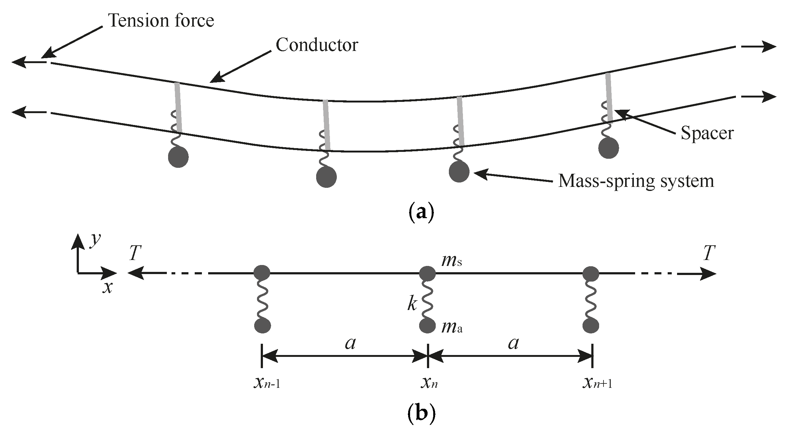
2. Model and BG Calculation Method

Generally, the bundle conductors are equipped with spacers. The spacer firstly could prevent the collision of adjacent transmission lines, and also could reduce the Aeolian vibration and sub-span oscillation, especially for the reduction of the sub-span oscillation. Currently, many anti-galloping measures realize the functions from introducing dampers and galloping proof devices to spacers. Thus, we also consider the construction of PC transmission lines from the change of spacers in order to do not significantly change the overall structure of transmission lines. In order to introduce PC into transmission lines, we need to give transmission lines certain periodical characters. One direct way involves arranging the spacers equally. Then, the transmission-spacer system would show periodicity because of the spacers. Surely, the equally spaced arrangement of spacers is not consistent with the currently used arrangement principle of spacers. The spacers usually have unequally spaced arrangement, in order to make the sub-span oscillation have logarithmic decrement because of the damping [41]. However, when the rigid spacers neglecting damping are used, the equally spaced arrangement is still suggested, although the rigid spacers have a weaker reduction effect than the damping spacers on the sub-span oscillation. Actually, using the BG property to reduce vibrations has nothing to do with damping. Thus, here we just consider the rigid spacers to combine PC and transmission lines, and the equally spaced arrangement of spacers is rational. After all, in terms of harmfulness, the effective reduction of galloping is more urgent than the sub-span oscillation control. Additionally, if the BG property is proved to be effective, controlling the sub-span oscillation by using the BG property also could be considered, for the sub-span oscillation is just a kind of vibration of transmission lines, which usually covers the frequency range of 1–3 Hz.
Figure 1a shows an example of a twin conductor bundle that illustrates the PC transmission line. Certainly, the twin conductor bundle also could be the arbitrary number of conductor bundle. The conductor bundle is in the static equilibrium position under weights and tensions. When meeting the conditions, wind disturbance could lead to galloping around the equilibrium position. Although galloping usually has the vertical component, horizontal component, and even torsional component, the largest vertical component directly determines the huge amplitude of galloping. So we think when the vertical component of galloping is reduced, the disadvantage of galloping would be basically removed. Thus, in order to introduce the locally resonant PC, we set additional mass-spring system on each of the equally spaced arranged spacers along the vertical direction to interfere with the vertical transverse vibration of transmission lines.
For model simplification, we just consider the vertical transverse vibration of transmission lines, assume that the conductors in a bundle always apart from each other with an unchanged distance, and also assume that the transmission line’s sag-to-span ratio is small. On these bases, we give the simplified model of a PC transmission line, which is shown in Figure 1b. The sagged conductor bundle is simplified as a single straight one. The spacer is considered as the lumped mass ms. The mass-spring system attached on the spacer has the spring stiffness of k, and the mass of ma. The tension force is T. The transmission line stretches along the x direction, and we focus on the motion of the system in y direction. The periodical length in x direction is a. The transverse displacement at the coordinate x and time t of the transmission line is y(x,t).
In order to study the BG property of the PC transmission line, we should obtain the frequency dispersion relation of the vertical transverse vibration of the system. So, we need to establish the calculation method of the frequency dispersion relation primarily. For this one dimensional system, the transfer matrix method is preferred to use [42]. We would derive the method below.
Each segment of the transmission line between two adjacent spacers is surly a taut catenary. Under the tension force T, the free vertical transverse vibration is governed by
2 y ( x , t ) x 2 = 1 V 2 2 y ( x , t ) t 2
where V = (T/ρl)1/2 is the wave velocity and ρl is the mass per unit length of the transmission line.
For a harmonic solution y(x,t) = v(x)exp(iωt) with separable variables, the vibration amplitude can be written as
v ( x ) = A cos ( α x ) + B sin ( α x )
where α = ω/V, A, and B are the undetermined state parameters and ω is the circular frequency.
So for the n-th primitive cell between the coordinate xn−1 and xn, the vibration amplitude of the transmission line can be given as
v n ( x L ) = A n cos ( α x L ) + B n sin ( α x L )
where xL is the local coordinate corresponding to the coordinate x in the n-th primitive cell, xL = xxn−1, and xL ∈ [0,a]; An and Bn are the undetermined state parameters of the n-th primitive cell.
Then, the vibration amplitude of the (n+1)-th primitive cell of the transmission line can be similarly given as
v n + 1 ( x L ) = A n + 1 cos ( α x L ) + B n + 1 sin ( α x L )
So, considering the n-th primitive cell, the vibration amplitude at x = xn is Ancos(αa)+Bnsin(αa); while considering the (n+1)-th primitive cell, the vibration amplitude at the same position is An+1. Certainly, the continuity of the displacement at x = xn gives
A n + 1 = A n cos ( α a ) + B n sin ( α a )
At the same time, the mass-spring system attached on the spacer also vibrates. For the n-th mass-spring system at x = xn, the harmonic solution of displacement could also be assumed to take the form of wn = unexp(iωt), where un is the amplitude.
Then, we consider the equilibrium condition at x = xn. When considering the n-th and (n+1)-th primitive cells, the tiny bending of the taut transmission line inevitably leads to the vertical component of the tension force T, which is Ty'(a,t) and Ty'(0,t) respectively. Additionally, at this position, the forces from the spacer, as well as the attached mass-spring system, also exist. So, we get
T y ( 0 , t ) + m s y ¨ ( 0 , t ) + m a w ¨ n = T y ( a , t )
where y' is the derivative of y on x, and y ¨ and w ¨ n are the accelerations of the spacer and attached mass. Substituting the related expressions into Equation (6) leads to
T B n + 1 α ω 2 m s A n + 1 ω 2 m a u n = T [ A n α sin ( α a ) + B n α cos ( α a ) ]
Furthermore, for the attached mass, the equilibrium condition gives
k [ y n + 1 ( 0 , t ) w n ] = m a w ¨ n
So we get
u n = k A n + 1 k ω 2 m a
Substituting Equation (9) into Equation (7), and combining Equation (5) and Equation (7) gives
K Ψ n + 1 = H Ψ n
where Ψ = [ A B ] , K = [ 1 0 F 1 ] , H = [ cos ( α a ) sin ( α a ) sin ( α a ) cos ( α a ) ] , F = ω 2 T α [ m s + k m a k ω 2 m a ] .
If the periodical structure along the x direction has infinite periodicities, the undetermined status parameters must satisfy Bloch’s theorem [43].
Ψ n + 1 = exp ( i q a ) Ψ n
where q is the wave number.
Substituting Equation (11) into Equation (10) gives
[ K 1 H exp ( i q a ) I ] Ψ n = 0
where I is the 2 × 2 unit matrix. It follows that the eigenvalues are the roots of the determinant,
| K 1 H exp ( i q a ) I | = 0
Solving the eigenvalue problem in a specified range of frequency f = ω/2π, the corresponding wave number q could be determined for each discrete frequency f. So, we would obtain the frequency dispersion relation in a frequency range.

3. Results and Discussion

3.1. Existence of BGs in Galloping Frequency Range

We just take a single conductor as an example of the PC transmission line. The tension force is 38.8 kN. The Young’s modulus, Poisson’s ratio, and density of the material of the transmission line are 69 GPa, 0.3, and 2500 kg/m3, respectively. The cross section area and mass per unit length are 600 mm2 and 1.5 kg/m, respectively. We give the distance between the spacers as 20 m, and assume that the mass of a spacer is 0.5 kg. In the spacer, the vertical mass-spring system is installed, with a spring stiffness of 6.373 N/m and a mass of 1 kg. The resonance frequency of the mass-spring system is 0.402 Hz.
Using the transfer matrix method, the frequency dispersion relation of the vertical transverse vibration of the PC transmission line in 0–0.6 Hz is calculated and shown in Figure 2. Surely, the vertical transverse vibration in the transmission line without attached mass-spring system must yields the rules of the straight dash curve. However, the resonance of the mass-spring system cuts off the straight dash curve and generates a BG, which covers the range of 0.402–0.408 Hz. The BG starts from the resonance frequency of the mass-spring system, which exhibits that the BG is indeed a locally resonant BG. The modulus of the imaginary part of complex wave number leads to the spatial decay of wave, thus the wave with imaginary wave number could not propagate. The frequency range corresponding to the imaginary wave number just matches the BG range.
However, after all, the theoretical BG result is obtained based on the ideal infinite model, which is still different from the actual finite PC transmission line. Thus, the situation of the vertical transverse vibration in the finite PC transmission line should also be studied. The frequency response reflects the transfer capability of the excitation in a finite structure and is usually used to verify the existence of BGs of PCs, because the BG ranges make remarkable attenuations on the vibration transmissibility. So, we implement the frequency response test on the finite PC transmission line with a length of 300 m. Compared with the above-mentioned infinite case, we could just set 14 spacers according to a periodical length of 20 m. We apply the harmonic vertical transverse displacement impulse U1, which sweeps over a range of 0–0.6 Hz to one end of the finite PC transmission line and gets the displacement response U2 at the other end; then, the frequency response could be given as 20·lg (U2/U1), which is also shown in Figure 2. The corresponding finite transmission line, just without vertical mass-spring system in each spacer, is also considered for comparison. Clearly, the actual BG within which the impulses attenuates strongly, exists, and matches the theoretical BG very well. Then, the existence of BG in the PC transmission line is verified. The vertical transverse vibration, which falls into the BG range, would be remarkably reduced, so galloping would also be reduced in the BG range.
Surely, one can see that the BG of the PC transmission line exists, but its width is quite narrow. Although galloping usually occurs at certain frequencies between 0.15–1 Hz [10], we cannot expect that the narrow BG could just cover the galloping frequencies. Even the position of BG could be adjusted by using different mass-spring systems corresponding to the theoretical galloping frequencies, while some actual situations, such as the deviation of the tension, the amount of ice accretion, etc., could change the galloping frequencies. To deal with the alteration problem of galloping frequencies, the BG must be widened. If the BG is wide enough, even covering the range of 0.15–1 Hz, galloping would never be a threat. For the structural characters of the PC transmission line, the spacer and attached mass-spring system could be adjusted to affect the BG width. We will study the effect of changing the corresponding factors on the BG below.

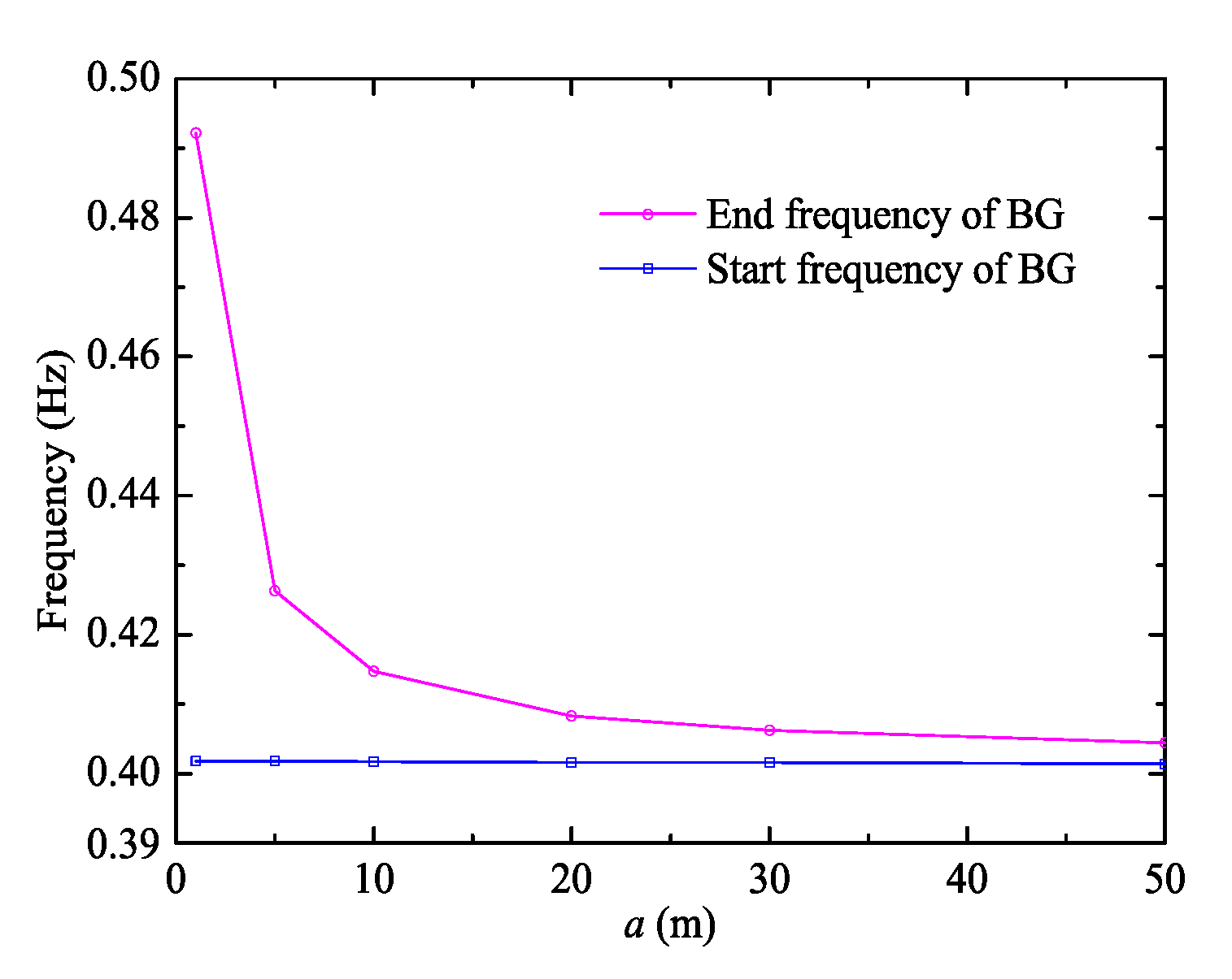
3.2. Effect of the Spacer on BG

Two parameters of the spacer could be adjusted: the periodical length and mass of the spacer. The periodical length of the PC transmission line is determined by the distance between two nearby spacers, so it is also the sub-span length. Based on the above-mentioned case, by just changing the periodical length, its influence on the BG is shown in Figure 3. Along with the increase of the periodical length, the BG width decreases sharply, which is the result of the unchanged start frequency and sharply decreased end frequency. The locally resonant PC determines that the start frequency of the BG never changes as long as the mass-spring system maintains, while the end frequency of the BG could be controlled by the periodical length. Clearly, increasing the numbers of the spacers on a certain transmission line helps to widen the BG. The BG could be widened to nearly 0.1 Hz by just relying on the decrease of the periodical length. Additionally, the decrease of the sub-span length also helps to reduce the sub-span oscillation, because the shorter sub-span length leads to smaller amplitude of sub-span oscillation. Therefore, the decrease of the periodical length of the PC transmission line benefits no only the BG widening, so as to reduce galloping better, but also the sub-span oscillation reduction.
The mass of the spacer is also an important parameter that could be designed. From just changing the mass of the spacer, its influence on the BG is shown in Figure 4. Similarly, as in the case of the periodical length, the start frequency of the BG never changes. Along with the increase of the mass of the spacer, the BG width decreases. The mass of the spacer could change the BG width by controlling the end frequency of the BG, although the rangeability is very limited. The lighter spacer gives the wider BG. So, in order to widen the BG, a relatively light spacer is preferred.

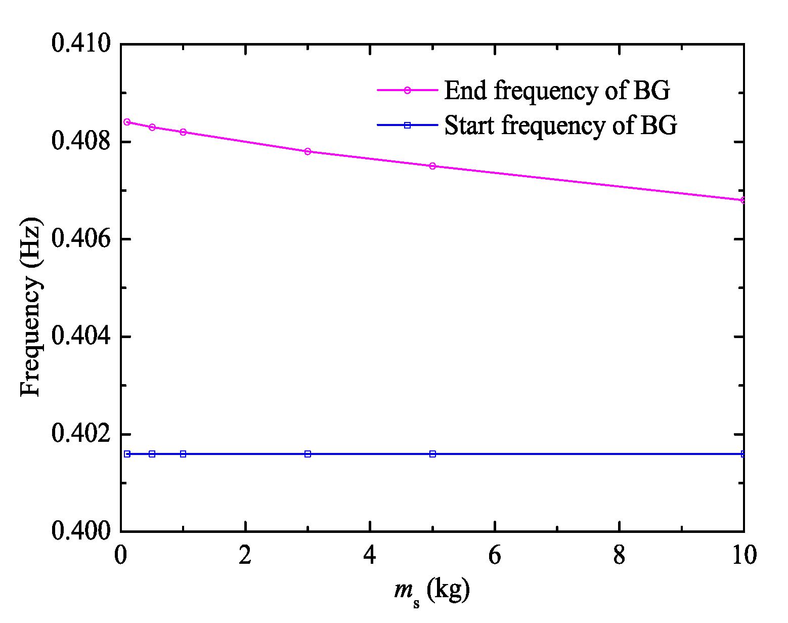
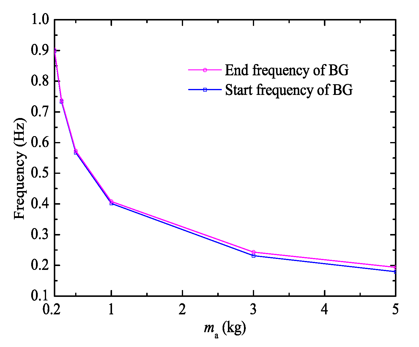
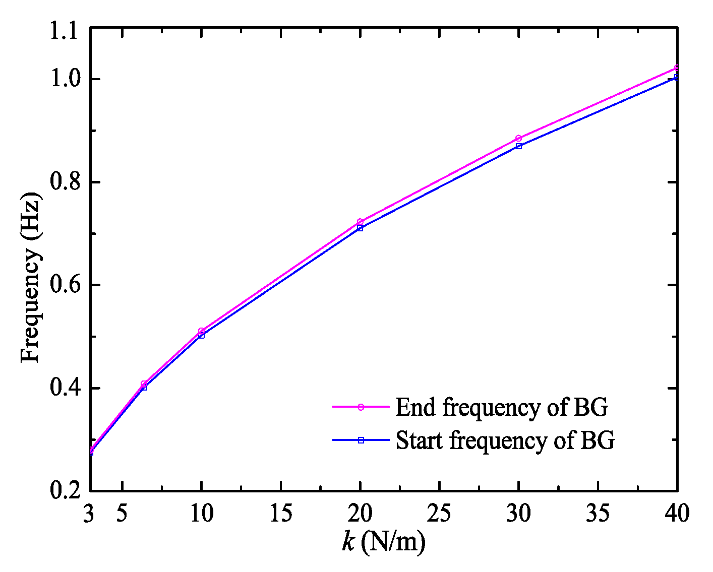
3.3. Effect of Attached Mass-Spring System on BG

Two parameters of the attached mass-spring system also could be adjusted: the mass and spring stiffness of the mass-spring system. As is well known, the ratio of the spring stiffness to the mass determines the resonance frequency of the attached mass-spring system, from which the position of the BG could be affected. Based on the primal case, from just changing the mass or spring stiffness of the mass-spring system, their influences on the BG are shown in Figure 5 and Figure 6, respectively. Surely, the increase of the mass and decrease of the spring stiffness both could reduce the resonance frequency of the attached mass-spring system, so the BG would move to the low frequency direction. Additionally, the increase of the mass and spring stiffness both contribute to the BG widening, although the rangeability is narrow. Thus, in the case of maintaining the resonance frequency, one could obtain the wider BG by proportionally increasing the mass and spring stiffness of the mass-spring system.

3.4. Remark

In general, the spacer and the mass-spring system both could affect the BG. Specifically, the resonance frequency of the attached mass-spring system determines the start frequency of the BG and BG position, while on this basis, the BG range could be widened by adjusting the parameters of the spacer, especially the periodical length. Of course, the four parameters (the periodical length, mass of the spacer, the mass and spring stiffness of the attached mass-spring system) all could be controlled to widen the BG, in spite of the differences in their effects. Clearly, decreasing the periodical length of the PC transmission line is the most effective way of widening the BG. However, one should also notice that, on the basis of using short periodical length, the multiple effects of widening the BG from adjusting the other three parameters still exist. Thus, in order to obtain a rather wide BG, the four parameters should be all considered. The basic principles include the decrease of the periodical length and mass of the spacer, as well as the increase of the mass and spring stiffness of the attached mass-spring system.
Under the guidance of this principle, based on the primal transmission line, we found a BG that could even cover the range of 0.338–0.909 Hz, which is shown in Figure 7, by using the following parameters: the periodical length is 1 m, the mass of a spacer is 0.1 kg, and the mass and spring stiffness of the attached mass-spring system are 10 kg and 45 N/m. Although the setting of the spacers and attached mass-spring systems may be a problem, the existence of super-wide BG gives us the confidence that the PC transmission line has the potential to solve the galloping problem. Besides the strongly targeted frequency range of galloping, compared with the existing anti-galloping methods, the PC transmission line just focuses on the vibration elimination of transmission lines rather than interfering with various galloping mechanisms. Thus, the method must have wider applicability.

4. Conclusions

In this paper, in order to solve the galloping problem of transmission lines, which seriously threaten the safety operation of the power grid due to their huge amplitude, we propose a method of combining the transmission lines and the PCs to reduce the vertical transverse vibration of the transmission lines, so as to reduce galloping. Based on the locally resonant mechanism of the PCs, we establish the two dimensional model of the PC transmission lines by periodically arranging the spacers with an attached mass-spring system along a transmission line. Then, the transfer matrix method is derived to calculate the frequency dispersion relation of the vertical transverse vibration of the PC transmission lines.
By implementing the calculation of the frequency dispersion relation on the infinite model and the test of frequency responses on the corresponding finite model, the vertical transverse vibration BG is confirmed in a single conductor, because the local resonance of the attached mass-spring system, the extremely low frequency BG (lower than 1 Hz), is readily obtained, which makes it possible to reduce the galloping that usually occurs at 0.15–1 Hz. In order to widen the BG range to cover the galloping frequency as much as possible, we also study the effects of the spacer and attached mass-spring system on the BG. We find that decreasing the periodical length and mass of the spacer, as well as increasing the mass and spring stiffness of the attached mass-spring system, all could bring a wider BG, and multiple effects exist when more than two factors are adjusted simultaneously. We even obtain the wide BG, which covers the range of 0.338–0.909 Hz, by just using a specific spacer and mass-spring system. So we believe that the PC transmission line has the potential to solve the problem of galloping, and even the sub-span vibrations, because of the BG property. The anti-galloping effect must be enhanced by combining the PC transmission line and the existing measures. We will continuously study the anti-galloping effect of the wide BGs in the next step and expect to test the method on a full-scale transmission line.

Acknowledgments

The authors would like to thank the support of the National Natural Science Foundation of China (Grant Nos. 51608173, 51579088, 51779087), the Natural Science Foundation of Jiangsu Province (Grant Nos. BK20150796, BK20161507), and the Fundamental Research Funds for the Central Public Welfare Scientific Research Institutes (Grant No. Y316022).

Author Contributions

Lin Han wrote the manuscript. Lin Han and Yan Zhang partially carried out the programming and calculation. Xiaomei Li, Linhua Jiang, and Da Chen collected and analyzed the results. All authors discussed the manuscript at all stages.

Conflicts of Interest

The authors declare no conflict of interest.

References

  1. Fu, X.; Li, H.; Li, J.; Zhang, P. A pounding spacer damper and its application on transmission line subjected to fluctuating wind load. Struct. Control Health Monit. 2017, 24, e1950. [Google Scholar] [CrossRef]
  2. Lu, M.L.; Popplewell, N.; Shah, A.H.; Chan, J.K. Hybrid nutation damper for controlling galloping power lines. IEEE Trans. Power Deliv. 2007, 22, 450–456. [Google Scholar] [CrossRef]
  3. Loredo-Souza, A.M.; Davenport, A.G. A novel approach for wind tunnel modelling of transmission lines. J. Wind Eng. Ind. Aerod. 2001, 89, 1017–1029. [Google Scholar] [CrossRef]
  4. Zhou, L.; Yan, B.; Zhang, L.; Zhou, S. Study on galloping behavior of iced eight bundle conductor transmission lines. J. Sound Vib. 2016, 362, 85–110. [Google Scholar] [CrossRef]
  5. Van Dyke, P.; Laneville, A. Galloping of a single conductor covered with a D-section on a high-voltage overhead test line. J. Wind Eng. Ind. Aerod. 2008, 96, 1141–1151. [Google Scholar] [CrossRef]
  6. Gurung, C.B.; Yamaguchi, H.; Yukino, T. Identification of large amplitude wind-induced vibration of ice-accreted transmission lines based on field observed data. Eng. Struct. 2002, 24, 179–188. [Google Scholar] [CrossRef]
  7. Fu, G.; Wang, L.; Guan, Z.; Hou, L.; Meng, X.; Macalpine, M. Simulations of the controlling effect of interphase spacers on conductor galloping. IEEE Trans. Dielect. Electr. Insul. 2012, 19, 1325–1334. [Google Scholar] [CrossRef]
  8. Yan, B.; Liu, X.; Lv, X.; Zhou, L. Investigation into galloping characteristics of iced quad bundle conductors. J. Vib. Control 2016, 22, 965–987. [Google Scholar] [CrossRef]
  9. Qin, Z.; Chen, Y.; Zhan, X.; Liu, B.; Zhu, K. Research on the galloping and anti-galloping of the transmission line. Int. J. Bifurcat. Chaos 2012, 22, 1250038. [Google Scholar] [CrossRef]
  10. Keutgen, R.; Lilien, J.L. A new damper to solve galloping on bundled lines. Theoretical background, laboratory and field results. IEEE Trans. Power Deliv. 1998, 13, 260–265. [Google Scholar] [CrossRef]
  11. Denhartog, J.P. Transmission line vibration due to sleet. Trans. Am. Inst. Electr. Eng. 1932, 51, 1074–1086. [Google Scholar] [CrossRef]
  12. Nigol, O.; Buchan, P.G. Conductor galloping part II Torsional mechanism. IEEE Trans. Power Appar. Syst. 1981, 708–720. [Google Scholar] [CrossRef]
  13. Luongo, A.; Piccardo, G. Linear instability mechanisms for coupled translational galloping. J. Sound Vib. 2005, 288, 1027–1047. [Google Scholar] [CrossRef]
  14. Wang, J.; Lilien, J.L. Overhead electrical transmission line galloping. A full multi-span 3-DOF model, some applications and design recommendations. IEEE Trans. Power Deliv. 1998, 13, 909–916. [Google Scholar] [CrossRef]
  15. Jones, K.F. Coupled vertical and horizontal galloping. J. Eng. Mech. 1992, 118, 92–107. [Google Scholar] [CrossRef]
  16. Havard, D.G.; Pohlman, J.C. Five years' field trials of detuning pendulums for galloping control. IEEE Trans. Power Appar. Syst. 1984, 318–327. [Google Scholar] [CrossRef]
  17. Xu, Z.D.; Xu, L.Z.; Xu, F.H. Study on the iced quad-bundle transmission lines incorporated with viscoelastic antigalloping devices. J. Dyn. Sys. Meas. Control 2015, 137, 61009. [Google Scholar] [CrossRef]
  18. Hunt, J.C.R.; Richards, D.J.W. Overhead-line oscillations and the effect of aerodynamic dampers. Proc. Inst. Electr. Eng. 1969, 116, 1869–1874. [Google Scholar] [CrossRef]
  19. Kushwaha, M.S.; Halevi, P.; Dobrzynski, L.; Djafari-Rouhani, B. Acoustic band structure of periodic elastic composites. Phys. Rev. Lett. 1993, 71, 2022–2025. [Google Scholar] [CrossRef] [PubMed]
  20. Jin, Y.; Pennec, Y.; Pan, Y.; Djafari-Rouhani, B. Phononic crystal plate with hollow pillars actively controlled by fluid filling. Crystals 2016, 6, 64. [Google Scholar] [CrossRef]
  21. Maldovan, M. Sound and heat revolutions in phononics. Nature 2013, 503, 209–217. [Google Scholar] [CrossRef] [PubMed]
  22. Chen, R.; Wu, T. Vibration reduction in a periodic truss beam carrying locally resonant oscillators. J. Vib. Control 2015, 22, 270–285. [Google Scholar] [CrossRef]
  23. Yan, Y.; Laskar, A.; Cheng, Z.; Menq, F.; Tang, Y.; Mo, Y.L.; Shi, Z. Seismic isolation of two dimensional periodic foundations. J. Appl. Phys. 2014, 116, 44908. [Google Scholar] [CrossRef]
  24. Sanchez-Dehesa, J.; Garcia-Chocano, V.M.; Torrent, D.; Cervera, F.; Cabrera, S.; Simon, F. Noise control by sonic crystal barriers made of recycled materials. J. Acoust. Soc. Am. 2011, 129, 1173–1183. [Google Scholar] [CrossRef] [PubMed]
  25. Mohammadi, S.; Eftekhar, A.A.; Hunt, W.D.; Adibi, A. High-Q micromechanical resonators in a two-dimensional phononic crystal slab. Appl. Phys. Lett. 2009, 94, 51906. [Google Scholar] [CrossRef]
  26. Wang, Y.; Maznev, A.; Laude, V. Formation of Bragg band gaps in anisotropic phononic crystals analyzed with the empty lattice model. Crystals 2016, 6, 52. [Google Scholar] [CrossRef]
  27. Liu, Z.; Zhang, X.; Mao, Y.; Zhu, Y.Y.; Yang, Z.; Chan, C.T.; Sheng, P. Locally resonant sonic materials. Science 2000, 289, 1734–1736. [Google Scholar] [CrossRef] [PubMed]
  28. Han, L.; Zhang, Y.; Jiang, L.; Zhang, Z. Free transverse vibration in periodically hinged identical beams on elastic foundations: A single material phononic crystal. Phys. Status Solidi-RRL 2013, 7, 514–517. [Google Scholar] [CrossRef]
  29. Yu, D.; Wen, J.; Zhao, H.; Liu, Y.; Wen, X. Flexural vibration band gap in a periodic fluid-conveying pipe system based on the Timoshenko beam theory. J. Vib. Acoust. 2011, 133, 14502. [Google Scholar] [CrossRef]
  30. Wang, Y.F.; Wang, Y.S.; Laude, V. Wave propagation in two-dimensional viscoelastic metamaterials. Phys. Rev. B 2015, 92, 104110. [Google Scholar] [CrossRef]
  31. Graczykowski, B.; Sledzinska, M.; Alzina, F.; Gomis-Bresco, J.; Reparaz, J.S.; Wagner, M.R.; Sotomayor, C.M. Phonon dispersion in hypersonic two-dimensional phononic crystal membranes. Phys. Rev. B 2015, 91, 95414. [Google Scholar] [CrossRef]
  32. Delpero, T.; Schoenwald, S.; Zemp, A.; Bergamini, A. Structural engineering of three-dimensional phononic crystals. J. Sound Vib. 2015, 363, 156–165. [Google Scholar] [CrossRef]
  33. Shi, Z.; Huang, J. Feasibility of reducing three-dimensional wave energy by introducing periodic foundations. Soil Dyn. Earthq. Eng. 2013, 50, 204–212. [Google Scholar] [CrossRef]
  34. Sharma, B.; Sun, C.T. Local resonance and Bragg bandgaps in sandwich beams containing periodically inserted resonators. J. Sound Vib. 2016, 364, 133–146. [Google Scholar] [CrossRef]
  35. Xiao, Y.; Mace, B.R.; Wen, J.; Wen, X. Formation and coupling of band gaps in a locally resonant elastic system comprising a string with attached resonators. Phys. Lett. A 2011, 375, 1485–1491. [Google Scholar] [CrossRef]
  36. Wang, T.; Sheng, M.; Qin, Q. Multi-flexural band gaps in an Euler–Bernoulli beam with lateral local resonators. Phys. Lett. A 2016, 380, 525–529. [Google Scholar] [CrossRef]
  37. Ding, L.; Zhu, H.P.; Luo, H.; Yin, T. Flexural wave propagation and localization in periodic jointed tunnels subjected to moving loads. J. Vib. Control 2016, 22, 2788–2804. [Google Scholar] [CrossRef]
  38. Shu, H.; Shi, X.; Li, S.; Liu, S.; Wang, W.; Shi, D. Numerical research on dynamic stress of phononic crystal ROD in longitudinal wave band gap. Int. J. Mod. Phys. B 2014, 28, 1450231. [Google Scholar] [CrossRef]
  39. Xiao, Y.; Wen, J.H.; Wen, X.S. Longitudinal wave band gaps in metamaterial-based elastic rods containing multi-degree-of-freedom resonators. New J. Phys. 2012, 14, 33042. [Google Scholar] [CrossRef]
  40. Yu, D.; Liu, Y.; Wang, G.; Cai, L.; Qiu, J. Low frequency torsional vibration gaps in the shaft with locally resonant structures. Phys. Lett. A 2006, 348, 410–415. [Google Scholar] [CrossRef]
  41. Zhu, D.L.; Ma, C. Study on sub-span oscillation of bundle conductor for transmission line. Adv. Mater. Res. 2012, 594–597, 2815–2818. [Google Scholar] [CrossRef]
  42. Han, L.; Zhang, Y.; Ni, Z.; Zhang, Z.; Jiang, L. A modified transfer matrix method for the study of the bending vibration band structure in phononic crystal Euler beams. Physica B 2012, 407, 4579–4583. [Google Scholar] [CrossRef]
  43. Kittel, C. Introduction to Solid State Physics; Wiley: New York, NY, USA, 2005. [Google Scholar]
Figure 1. (a) Schematic representation and (b) computational model of the phononic crystal (PC) transmission line. The spacers equipped with vertical mass-spring system are equally spaced arranged.
Crystals 07 00346 g001
Figure 2. The frequency dispersion relation (left, solid line), the attenuation properties illustrated by the modulus of the imaginary part of complex wave number (middle), and the frequency responses (right, solid line) of a PC transmission line. The tension force of the transmission line is 38.8 kN. The periodical length is 20 m. The mass of a spacer is 0.5 kg. The vertical mass-spring system installed in the spacer has a spring stiffness of 6.373 N/m and a mass of 1 kg. The shadow area indicates the band gaps (BG) range. The case of the transmission line without the vertical mass-spring system is also illustrated for comparison (dash line).
Crystals 07 00346 g002
Figure 3. The BG range of the PC transmission line along with the change of the periodical length based on the model with a tension force of 38.8 kN, the mass of a spacer of 0.5 kg, the spring stiffness, and mass of the attached mass-spring system of 6.373 N/m and 1 kg.
Crystals 07 00346 g003
Figure 4. The BG range of the PC transmission line along with the change of the mass of spacer based on the model with the tension force of 38.8 kN, the periodical length of 20 m, the spring stiffness, and mass of the mass-spring system of 6.373 N/m and 1 kg.
Crystals 07 00346 g004
Figure 5. The BG range of the PC transmission line along with the mass of the attached mass-spring system based on the model with the tension force of 38.8 kN, the periodical length of 20 m, the mass of a spacer of 0.5 kg, and the spring stiffness of the attached mass-spring system of 6.373 N/m.
Crystals 07 00346 g005
Figure 6. The BG range of the PC transmission line along with the spring stiffness of the attached mass-spring system based on the model with the tension force of 38.8 kN, the periodical length of 20 m, the mass of a spacer of 0.5 kg, and the mass of the attached mass-spring system of 1 kg.
Crystals 07 00346 g006
Figure 7. The frequency dispersion relation (left) and the attenuation properties illustrated by the modulus of the imaginary part of complex wave number (right) of a PC transmission line. The tension force of the transmission line is 38.8 kN. The periodical length is 1 m. The mass of a spacer is 0.1 kg. The vertical mass-spring system installed in each spacer has the spring stiffness of 45 N/m, and the mass of 10 kg. The shadow area indicates a wide BG.
Crystals 07 00346 g007

