Abstract
This study presents a comparative analysis of fatigue crack growth (FCG) in four high-performance crystalline metallic alloys: Inconel 718, Ti-6Al-4V, Aluminum 7075-T6, and ASTM A514 Steel. The Finite Element Method was utilized to simulate crack propagation and quantify the individual and synergistic effects of key material properties, including Paris Law constants (C and m), yield strength, and modulus of elasticity, on FCG behavior. The analysis integrates simulation-driven parametric studies to quantify the impact on performance indicators (fatigue life cycles, equivalent stress intensity factors, safety factors, von Mises stress, and strain energy), and provides a quantitative analysis of secondary parameters. The results provide a robust, data-driven framework for material selection in aerospace, industrial, and structural applications where fatigue life is a paramount design consideration. Key findings reveal that Inconel 718 exhibits vastly superior fatigue life which is approximately 15 times greater than the next best-performing material, ASTM A514 Steel. Conversely, Ti-6Al-4V demonstrated the lowest fatigue resistance.
1. Introduction
The escalating demand for high-performance materials across critical sectors like aerospace, industrial, and structural engineering necessitates a profound understanding of their mechanical behavior, particularly under cyclic loading conditions. Components in aerospace, automotive, energy, and heavy machinery industries are continuously subjected to cyclic stresses, which can lead to fatigue failure [1,2,3]. This refers to progressive, localized structural damage that develops from a material’s exposure to fluctuating stresses. FCG remains a predominant failure mechanism in components subjected to dynamic stresses, making its accurate prediction and mitigation paramount for ensuring structural integrity and extending operational lifespans. While many studies tend to focus on a single material class (e.g., aluminum alloys or steels) [4,5,6], a comparative analysis that systematically investigates the interplay of mechanical properties such as Paris Law parameters, yield strength, and modulus of elasticity across distinct high-strength material categories (e.g., advanced aluminum alloys, titanium alloys, nickel-based superalloys, High-Strength Low-Alloy (HSLA) Steels, and Quenched and Tempered steel) is often lacking. Such an analysis would offer valuable insights into their relative performance and trade-offs under fatigue loading, essential for multi-sector material selection.
This introduction explores the fatigue resistance and durability characteristics of four high-performance metallic alloys: Inconel 718 (Aged), Ti-6Al-4V, Aluminum 7075-T6, and ASTM A514 Steel. These materials are chosen due to their widespread use in demanding applications where their unique properties significantly contribute to the safety and longevity of engineered systems. Among these, Inconel 718, a nickel–chromium–molybdenum superalloy, is a cornerstone material in high-temperature applications such as jet engines, gas turbines, and rocket components due to its exceptional strength, corrosion resistance, and stability at elevated temperatures [7]. The aged condition of Inconel 718, achieved through specific heat treatments, significantly enhances its mechanical properties, particularly its fatigue strength. Inconel 718 exhibits fatigue crack issues primarily influenced by high temperatures, which accelerate crack propagation and can lead to oxidation-enhanced initiation [8,9]. One of the most significant advantages of Inconel 718 is its superior oxidation and corrosion resistance. This makes it an ideal choice for applications exposed to harsh environments, including those involving aggressive chemicals, high-temperature gases, and seawater. Its resistance to stress-corrosion cracking and pitting in chloride-containing environments further enhances its utility in marine and offshore applications. Furthermore, Inconel 718 exhibits excellent weldability compared to many other nickel-based superalloys, which often suffer from strain-age cracking during welding processes. This ease of fabrication allows for the creation of complex geometries and structures, expanding its applicability in intricate designs. Recent research has focused on understanding the very-high-cycle fatigue (VHCF) behavior of Inconel 718, especially in additively manufactured forms, highlighting the importance of microstructure and post-processing treatments like Hot Isostatic Pressing (HIP) in improving fatigue performance by reducing defects [10,11,12]. Studies indicate that optimized aging parameters can improve tensile and fatigue strengths, crucial for the long-term durability of components operating under severe cyclic thermal and mechanical loads [13].
Similarly, Ti-6Al-4V, an alpha-beta titanium alloy, is celebrated for its outstanding strength-to-weight ratio, excellent corrosion resistance, and biocompatibility, making it indispensable in aerospace, biomedical, and automotive industries. Its fatigue resistance is a critical property, particularly in aerospace structures where weight reduction is paramount without compromising safety. Ti-6Al-4V’s fatigue behavior is critically affected by defects from additive manufacturing, requiring post-processing for improvement, and it is susceptible to hydrogen embrittlement and dwell fatigue, which can severely reduce its performance [14,15]. Recent investigations into Ti-6Al-4V have explored the impact of additive manufacturing processes on its fatigue behavior, with findings suggesting that surface roughness and internal defects can significantly influence fatigue life [16,17,18]. The inherent durability of Ti-6Al-4V, including its resistance to general corrosion and stress corrosion cracking in various environments, ensures its sustained performance over extended periods, even in harsh conditions like marine applications [19].
Aluminum 7075-T6 is another high-strength alloy widely utilized in aircraft structures, defense applications, and high-performance sporting goods due to its impressive strength-to-weight ratio. Recent studies have focused on optimizing high-cycle fatigue predictions and understanding fatigue crack initiation in 7075-T6, emphasizing the role of microstructural features and surface quality [20,21,22,23]. Compared to other aluminum alloys, 7075-T6 offers superior fatigue strength, making it suitable for components subjected to repetitive loading. Its durability is also influenced by its corrosion resistance, though it can be more susceptible to stress corrosion cracking in certain environments compared to other aluminum alloys, necessitating careful design and surface protection strategies. Aluminum 7075-T6 faces challenges from stress ratio effects on crack growth, microstructural cracking influenced by heat treatment, and a high susceptibility to corrosion-fatigue, where pitting corrosion acts as a primary initiation site [24,25].
Finally, ASTM A514 is a high-strength, low-alloy (HSLA) steel characterized by its excellent combination of high yield strength, toughness, and weldability. It is extensively used in heavy construction, bridges, pressure vessels, and mining equipment, where robust structural integrity and durability are essential. The fatigue resistance of ASTM A514 Steel is crucial for these long-life structures, which are often subjected to significant cyclic loads. Research on ASTM A514 Steel has investigated its fatigue crack growth behavior under variable-amplitude loading, providing insights into its performance in real-world operational scenarios [26,27]. The overall durability of ASTM A514 Steel is attributed to its inherent strength, toughness, and resistance to brittle fracture, ensuring reliable performance and extended service life in demanding structural applications [28,29]. ASTM A514 Steel is particularly prone to fatigue crack initiation and propagation in weld areas and heat-affected zones due to residual stresses and microstructural changes, and its performance is also affected by variable-amplitude loading and the potential for reheat cracking [30]. Recent advancements in material science and manufacturing processes have further enhanced our understanding and capability to optimize these materials for improved fatigue and durability performance. Although the Paris Law and general material properties are well-understood, there is a gap in detailed, simulation-driven parametric studies that directly quantify the impact of these properties on key performance indicators (such as fatigue life cycles, equivalent stress intensity factors, safety factors, von Mises stress, and strain energy) across a range of high-strength materials. While this paper primarily delves into how macroscopic parameters, such as Paris constants and yield strength, influence fatigue crack growth (FCG), it is vital to recognize that these characteristics are not standalone. Instead, they are profoundly shaped by the underlying microstructural mechanisms inherent to the material. Indeed, features like grain size, the specific crystallographic orientation of grains, and the very presence of secondary phases or inclusions directly dictate a material’s inherent capacity to resist both crack propagation and plastic deformation. For example, a finer grain structure often enhances fatigue resistance, largely by encouraging the crack to deflect or branch, thereby dissipating energy. Conversely, the precise nature of any second phases present can either significantly hinder or, regrettably, accelerate the rate at which cracks grow [31]. Recent advancements in computational tools, such as the SMART crack growth feature in ANSYS Mechanical, have revolutionized the ability to perform detailed parametric studies, offering unprecedented insights into how various material properties influence FCG [32,33,34,35]. The novelty of this work lies in the systematic and comparative parametric study conducted across four distinct high-performance metallic alloys (Inconel 718, Ti-6Al-4V, Aluminum 7075-T6, and ASTM A514 Steel). While individual studies often focus on a single material class, a comprehensive, simulation-driven parametric analysis that directly quantifies the impact of key material parameters (Paris Law constants C and m, yield strength, and modulus of elasticity) on various fatigue performance indicators (fatigue life cycles, equivalent stress intensity factors, safety factors, von Mises stress, and strain energy) across such a diverse range of materials is, to our knowledge, not widely available in the literature. This comparative approach provides unique insights into the relative performance and trade-offs of these materials under fatigue loading, which is crucial for multi-sector material selection and robust design practices. The chosen materials are widely used in critical aerospace, industrial, and structural engineering applications. By providing a detailed simulation-driven analysis of their FCG behavior, this work offers practical insights that can directly inform design practices, improve fatigue life predictions, and enhance the safety and longevity of engineered systems in these sectors.
The main objectives of this study are:
- To systematically investigate the influence of key material properties (Paris Law constants C and m, yield strength, and modulus of elasticity) on fatigue crack growth (FCG) behavior.
- To quantify and compare the fatigue performance of four distinct high-strength alloys—Inconel 718, Ti-6Al-4V, Aluminum 7075-T6, and ASTM A514 Steel—under identical simulated loading conditions.
- To develop a data-driven framework that correlates material parameters with critical performance indicators (fatigue life, stress intensity factors, and safety factors) to aid in material selection for fatigue-critical applications.
2. Numerical Analysis
This study employs the finite element method for the parametric evaluation of FCG in high-performance metallic alloys, utilizing ANSYS 2022 R1 with its advanced SMART crack growth feature. This robust computational tool is selected for its capability to accurately simulate crack propagation under cyclic loading conditions, providing a comprehensive framework for analyzing complex material behaviors.
2.1. Model Setup and Simulation Methodology
This study utilizes ANSYS’s pre-meshed crack modeling approach, specifically through its SMART crack growth tool. This method is essential for calculating the Stress Intensity Factor (SIF) at the crack front, a critical failure criterion in fracture mechanics. Stress Intensity Factors (SIFs) are calculated using the J-integral method, which is a robust and widely accepted technique in fracture mechanics. The J-integral is evaluated along a contour surrounding the crack tip, providing accurate SIF values even in the presence of localized plasticity.
For each material investigated, a representative finite element model will be constructed, incorporating appropriate geometries and boundary conditions to simulate the intended loading scenarios. Instead of explicit time integration per cycle, the model simulates fatigue crack growth as a cycle-dependent process using Paris’s Law, where crack growth rate is a function of the stress intensity factor range. The ANSYS SMART crack growth feature automates this by incrementally advancing the crack front based on calculated stress intensity factors and material-specific Paris Law parameters. Mesh refinement will be applied in the vicinity of the crack tip to ensure accurate stress intensity factor calculations, which are critical for predicting crack propagation. The SMART crack growth feature automates the crack propagation process by remeshing the crack front based on calculated stress intensity. Utilizing the Unstructured Mesh Method (UMM) with automated tetrahedral meshing for the crack front significantly reduces pre-processing time and improves accuracy by enabling automatic crack front updates during the simulation. This iterative process allows for the simulation of crack path and growth rate over numerous loading cycles. In ANSYS, the determination of crack growth direction, specifically the path angle, relies on the widely accepted maximum circumferential stress theory. This theory is one of several proposed explanations for crack propagation, each designed for different material behaviors and loading conditions, and it postulates that cracks extend perpendicular to the maximum tensile stress. The crack growth angle is calculated using the following formula [36,37]:
The variables KI and KII correspond to the individual crack opening modes quantified by stress intensity factors. To determine the crack propagation rate, a modified Paris law is then applied, defined as:
where is the equivalent stress intensity factor, and C and m are the coefficient and exponent of Paris’ law, respectively. The Paris Law coefficient represents the crack growth rate at a unit stress intensity factor range. A lower ‘C’ value signifies a slower crack growth rate, indicating higher resistance to fatigue crack propagation and, consequently, a longer fatigue life. Both ‘C’ and ‘m’ are not absolute material constants but can be influenced by various factors, including environmental conditions, frequency, temperature, stress ratio, and the material’s microstructure. Understanding these parameters is crucial for predicting fatigue life, designing against fatigue failure, and selecting appropriate materials for applications subjected to cyclic loading. The Paris Law exponent ‘m’ indicates the sensitivity of the crack growth rate to changes in the stress intensity factor range. Typically, for many engineering materials, the value of ‘m’ ranges between 2 and 4, with values near 4 being common for metallic materials. A higher ‘m’ value implies that the crack growth rate is highly sensitive to the applied stress intensity, meaning that even small increases in stress can lead to a significant acceleration in crack propagation. Conversely, a lower ‘m’ suggests a more stable crack growth behavior [38].
The calculation of this equivalent stress intensity factor range is achieved using the subsequent equation [39]:
2.2. Parametric Evaluation
To understand the influence of key material properties on FCG, a systematic parametric study will be conducted. The primary parameters to be varied include:
- Paris Law Constants (C and m): These empirical constants, fundamental to FCG prediction, will be adjusted to reflect the FCG characteristics of different material classes and conditions.
- Yield Strength: The material’s resistance to plastic deformation will be varied to assess its impact on crack initiation and propagation behavior.
- Modulus of Elasticity (Young’s Modulus): This measure of stiffness will be altered to observe its effect on stress distribution and overall structural response.
For each material type these parameters will be systematically adjusted within realistic ranges to quantify their individual and synergistic effects on FCG. This approach will enable a detailed understanding of how variations in these properties affect the fatigue performance of components.
2.3. Data Extraction and Analysis
Upon completion of each simulation, critical performance indicators will be extracted and analyzed. These include:
- Equivalent Stress Intensity Factors (Keq): Calculated at the crack tip to characterize the driving force for crack propagation.
- Fatigue Life Cycles: The total number of cycles to failure for each simulated scenario.
- Von Mises Stress Distribution: To visualize and quantify the stress state within the component, particularly around the crack path.
- Strain Energy: To assess the energy absorbed by the material during deformation and crack growth.
- Safety Factors: Derived from the ratio of material strength to applied stress, providing insight into structural reliability.
This comprehensive data set will facilitate a comparative analysis across diverse material classes, allowing for the identification of optimal material selections and design practices for applications where fatigue life is a paramount consideration. The simulation-driven parametric studies will provide a robust, data-driven framework for enhancing fatigue life predictions and improving the overall durability of engineered systems.
2.4. Mesh Convergence Verification
To guarantee the fidelity of the simulation, a mesh sensitivity study was undertaken to identify an optimal element size that balances computational cost with precision. This process is a cornerstone of the FEM, ensuring that the numerical solution is independent of the mesh discretization. The study focused on predicting the fatigue life of Inconel 718. The analysis was conducted under a specific load condition with a stress ratio of R = 0.1. As detailed for the notched plate with a hole geometry in Table 1, the mesh was systematically refined. An element size of 1 mm yielded an equivalent stress intensity factor of 1407 MPa mm0.5. This result was validated by refining the mesh to 0.5 mm, which produced a value of 1421.4 MPa mm0.5, confirming convergence with a marginal 1% deviation.

Table 1.
Mesh Convergence analysis.
This negligible variation confirmed that the 1 mm element size is sufficient for achieving reliable and accurate results without the need for further, more computationally expensive, mesh refinement. This state, known as mesh independence, is critical for validating the simulation’s findings. For a clearer, more intuitive grasp of this convergence behavior, the results of the sensitivity analysis are visually charted in Figure 1.
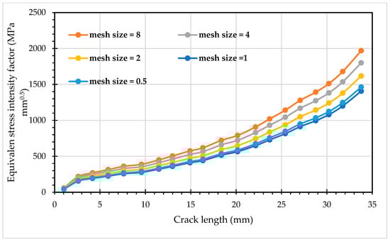
Figure 1.
Mesh Convergence Analysis for Inconel 718: Equivalent Stress Intensity Factor versus Crack Length.
3. Numerical Results and Discussion
This numerical analysis is fundamentally rooted in the experimental FCG studies conducted by Giner et al. [40] on Aluminium 7075-T6 rectangular specimens. This foundational work provides a critical benchmark and validation framework for extending the analysis to three additional materials which are: Inconel 718 (Aged), Ti-6Al-4V and ASTM A514 Steel. The mechanical properties for all four materials are detailed in Table 2. Additionally, Figure 2 provides a visual representation of the single-edge notched tension specimen and the applied boundary conditions. This specimen was selected because it is a standard and widely accepted specimen configuration for fatigue crack growth studies, allowing for direct comparison with existing literature and experimental data. The pre-crack in this geometry is a sharp crack with a virtually zero crack-tip radius. A cyclic load of 20 kN was applied to the upper and lower holes shown in Figure 2. This load had a constant amplitude and a load ratio (R) of 0.1. Plane strain conditions were maintained during the simulation to accurately represent the material’s behavior under these loading conditions. ANSYS generated the initial mesh, depicted in Figure 2, with a 1 mm element size, resulting in 581,980 nodes and 398,566 elements. This study builds upon the preliminary finite element analysis for Aluminum 7075-T6 presented in a previous article [41]. This study expands upon that work by providing further explanation and introducing three new high-performance metals: Inconel 718, Ti-6Al-4V, and ASTM A514 Steel.
Table 2.
Mechanical Properties of Four Case Study Metals.
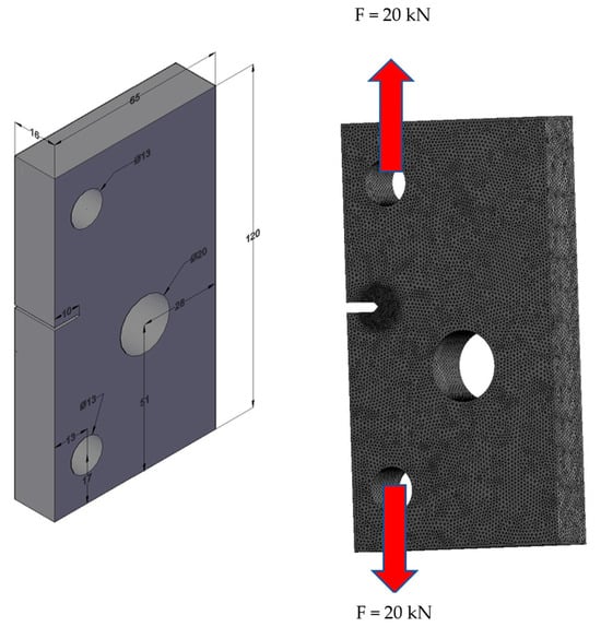
Figure 2.
Geometric Configuration (left) (units in mm) and Mesh of the Notched Plate with Hole (right).
In the preceding study, the crack growth path simulated using ANSYS software for Aluminum 7075-T6 exhibited remarkable consistency with independently derived results. Specifically, its predictions strongly aligned with experimental findings reported by Giner et al. [40]. Furthermore, the ANSYS simulation demonstrated excellent agreement with numerical outcomes from two distinct investigations: those by Cheng and Wang [45] who employed the Extended Finite Element Method (XFEM) coupled with a decomposed updating reanalysis method, and those by Jafari et al. [46], who utilized COMSOL software incorporating an enhancement strategy compatible with its framework. This consistent validation across diverse methodologies, encompassing experimental, XFEM, and COMSOL-based numerical approaches, underscores the reliability and accuracy of the ANSYS simulation in predicting the crack growth path for the specific geometry and material under consideration. Similarly, in the present study, the crack growth path remained unchanged for the other three materials investigated: Inconel 718 (Aged), Ti-6Al-4V, and ASTM A514 Steel. This consistent behavior is attributed to the linear elastic material properties of these materials, which, like Aluminum 7075-T6, do not exhibit significant deviations in crack growth path under the simulated conditions. This section presents a comprehensive analysis of crack growth paths derived from ANSYS simulations for four distinct engineering materials: Inconel 718 (Aged), Ti-6Al-4V, Aluminum 7075-T6, and ASTM A514 Steel (Figure 3a–d). These computational results are critically evaluated against an experimental crack path obtained by Giner et al. [40] for Aluminum 7075-T6 as displayed in Figure 3e. The primary focus of this analysis is on the maximum principal stress contours, which serve as a fundamental indicator of stress distribution and, consequently, the trajectory of crack propagation within the material. A thorough understanding of these stress fields is paramount for accurately predicting both the direction and extent of crack growth. Analysis of maximum principal stress contours revealed that while Aluminum 7075-T6 and Inconel 718 (Aged) showed complete crack propagation, Ti-6Al-4V and ASTM A514 Steel exhibited incomplete crack growth.
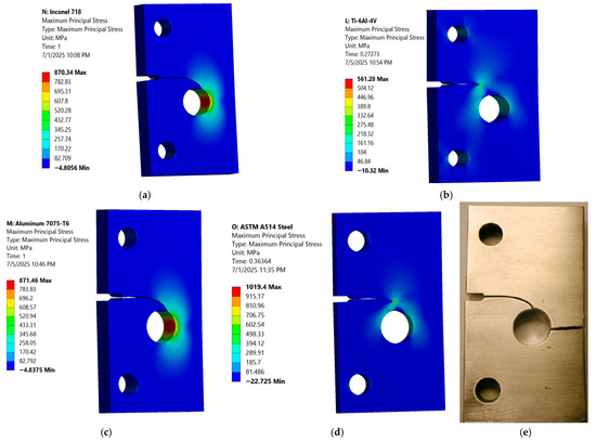
Figure 3.
Crack growth path (a) Inconel 718 (Aged), (b) Ti-6Al-4V, (c) Aluminum 7075-T6, (d) ASTM A514 Steel, and (e) Experimental [40].
This incomplete crack growth is attributed to the higher fracture toughness of Ti-6Al-4V and ASTM A514 Steel, which necessitates a greater stress intensity at the crack tip for full propagation. This indicates their enhanced resistance to crack extension under the simulated conditions, thereby requiring higher applied stresses or more extensive loading to achieve complete crack growth.
The numerical simulation for Aluminum 7075-T6 was rigorously validated using experimental data from Giner et al. [40] and further corroborated by numerical outcomes from other studies [45,46], it is recognized that direct experimental validation for Inconel 718, Ti-6Al-4V, and ASTM A514 Steel was not performed within the scope of this study. A statement has been added to clarify that the consistent crack growth path observed across all materials in the simulations is attributed to their linear elastic material properties under the simulated conditions, similar to Aluminum 7075-T6. However, it has been emphasized that future research will aim to include experimental validation for these additional materials to further strengthen the conclusions.
The contour plots of total deformation provide crucial visual insights into how each material responds to the applied cyclic load, complementing numerical data by illustrating the distribution of stress and deformation across the specimen, particularly highlighting areas of high stress concentration around the crack tip and holes. Specifically, Inconel 718 (Aged) exhibits a total deformation of 0.69661 mm (Figure 4a), which, while higher than ASTM A514 Steel, is significantly lower than Ti-6Al-4V and Aluminum 7075-T6, with deformation localized around the crack tip, indicating its high stiffness and resistance to widespread deformation, consistent with its high modulus of elasticity. The total deformation contour for Ti-6Al-4V shows a relatively low maximum of 1.308 mm (Figure 4b), concentrated around the crack tip and upper hole, with a smooth color gradient indicating a transition from high to lower deformation, consistent with its moderate modulus of elasticity. In contrast, Aluminum 7075-T6 exhibits the highest total deformation at 9.6685 mm (Figure 4c), with significant deformation spreading across a larger area, especially around the crack path, directly attributable to its lowest modulus of elasticity and lower strength, making it the most flexible and prone to deformation.
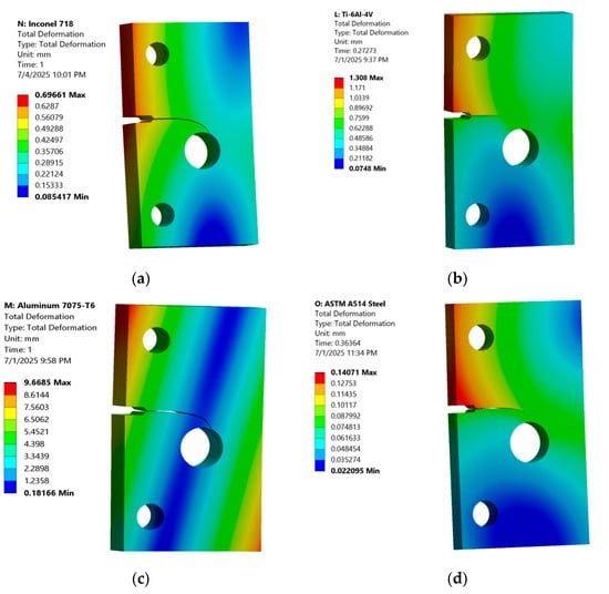
Figure 4.
Contour Plot of Total Deformation (a) Inconel 718 (Aged), (b) Ti-6Al-4V, (c) Aluminum 7075-T6, and (d) ASTM A514 Steel.
Finally, ASTM A514 Steel shows a notably low total deformation of 0.14071 mm (Figure 4d), the lowest among all materials, even surprising given its slightly lower modulus of elasticity than Inconel 718, suggesting exceptional stiffness and resistance to overall displacement under the applied load, a favorable characteristic for structural integrity.
The von Mises stress contour plots provide critical insights into the stress distribution and concentration within each material under cyclic loading, particularly highlighting the behavior around the crack tip. Inconel 718 exhibits a maximum von Mises stress of 830.01 MPa (Figure 5a), with stress highly concentrated at the crack tip. This value is below its yield strength (1030 MPa), suggesting that Inconel 718 remains within its elastic limit even at the point of highest stress concentration, indicating its superior strength and resistance to plastic deformation. Ti-6Al-4V shows the lowest maximum von Mises stress of 357.97 MPa (Figure 5b), which is well below its yield strength (828 MPa), indicating that the material remains entirely within its elastic range, even at the crack tip. This low stress level, combined with its relatively short crack length, suggests that Ti-6Al-4V manages stress distribution effectively, despite its lower number of cycles compared to Inconel 718.
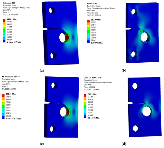
Figure 5.
Contour Plot of the von Mises stress (a) Inconel 718 (Aged), (b) Ti-6Al-4V, (c) Aluminum 7075-T6, and (d) ASTM A514 Steel.
In contrast, the von Mises stress contour for Aluminum 7075-T6 shows a maximum stress of 830.41 MPa (Figure 5c), a value significantly higher than its yield strength (469 MPa), indicating extensive plastic deformation at the crack tip and surrounding areas. The contour plot visually confirms this, showing a larger region of high stress (red/orange) compared to the other materials, signifying that the material has yielded considerably under the applied load. Lastly, the von Mises stress contour for ASTM A514 Steel shows a maximum stress of 732.9 MPa (Figure 5d). The stress concentration is clearly visible at the crack tip, with a rapid decrease in stress away from this critical region. This value is close to its yield strength (690 MPa), indicating that localized yielding might occur at the crack tip, but the overall structure remains largely elastic.
The strain energy quantifies the energy absorbed by a material during deformation; a higher strain energy indicates either greater deformation or a superior capacity to absorb energy before fracturing. Inconel 718, as depicted in Figure 6a, demonstrates a moderate strain energy of 4.354 mJ, reflecting a balanced combination of stiffness and energy absorption prior to deformation. Following this, Ti-6Al-4V exhibits a strain energy of 6.88 mJ (Figure 6b), showcasing its capacity for energy absorption in relation to its moderate deformation. Aluminum 7075-T6, with the highest strain energy of 12.139 mJ (Figure 6c), aligns with its substantial total deformation and pronounced plastic behavior. Conversely, ASTM A514 Steel displays the lowest strain energy at 0.775 mJ (Figure 6d), suggesting a very stiff material that undergoes minimal deformation under the applied load.
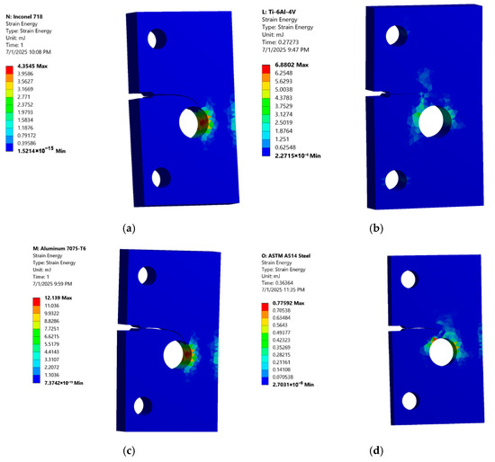
Figure 6.
Contour Plot of the strain energy (mJ) (a) Inconel 718 (Aged), (b) Ti-6Al-4V, (c) Aluminum 7075-T6, and (d) ASTM A514 Steel.
To enhance the understanding of how each material responds to stress, it is crucial to examine their respective safety factors, which quantify their resistance to yielding under the applied loads. The safety factor (SF) is calculated as the ratio of the material’s yield strength to the maximum equivalent (von Mises) stress. A safety factor greater than 1 indicates that the material is operating within its elastic limit and is not expected to yield, while a safety factor less than 1 suggests that yielding has occurred or is expected. Figure 7 presents the safety factor contours for four different materials under similar loading conditions, revealing distinct behaviors. For (a) Inconel 718 (Aged), a safety factor of approximately 1.24 (1030 MPa/830.01 MPa) indicates a good safety margin, as the maximum stress remains well below the yield strength, aligning with its excellent fatigue life. (b) Ti-6Al-4V exhibits the highest safety factor at roughly 2.31 (828 MPa/357.97 MPa), signifying that this material operates far below its yield strength, a significant advantage in preventing plastic deformation, even if its overall fatigue life is not as high as Inconel 718. Conversely, (c) Aluminum 7075-T6 displays a significantly low safety factor of approximately 0.56 (469 MPa/830.41 MPa), confirming considerable plastic deformation under the applied load, which is consistent with its poor fatigue performance and high total deformation. Lastly, (d) ASTM A514 Steel shows a safety factor of about 0.94 (690 MPa/732.9 MPa), slightly less than 1, suggesting that localized yielding is likely occurring at the crack tip; while not as severe as Aluminum 7075-T6, it indicates that this material operates closer to its yield limit under these specific loading conditions.
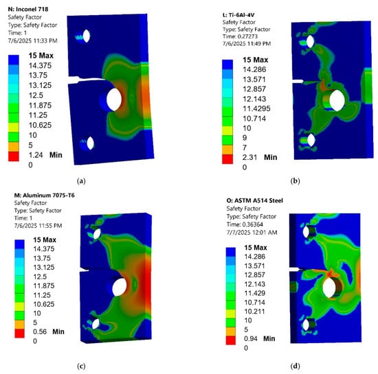
Figure 7.
Contour Plot of the safety factor (a) Inconel 718 (Aged), (b) Ti-6Al-4V, (c) Aluminum 7075-T6, and (d) ASTM A514 Steel.
The fatigue life cycles directly measure each material’s resistance to crack initiation and propagation under cyclic loading. The initial cycles (e.g., 4.15 million for Inconel 718) represent the point at which stable crack propagation begins after an initial crack initiation and incubation period. The simulation focuses on the propagation phase, assuming that crack initiation has already occurred. The variation in starting cycles for different materials is due to their inherent fatigue resistance and the specific Paris Law parameters, which dictate the rate of crack growth. As shown in Figure 8, Inconel 718 exhibits an exceptionally high number of fatigue cycles, reaching into the millions (e.g., 4,376, 100 cycles in the provided data). This outstanding performance is directly attributable to its superior mechanical properties, including its high ultimate tensile strength (1250 MPa), yield strength (1030 MPa), and modulus of elasticity (200 GPa). Furthermore, its low Paris Law coefficient ‘C’ (1.0 × 10⁻¹²) indicates a very slow crack growth rate, meaning that even if a crack initiates, it propagates very slowly, contributing to a significantly extended fatigue life. The high safety factor (1.24) calculated previously also supports this, indicating that the material operates well within its elastic limits, minimizing plastic deformation that could accelerate crack growth.
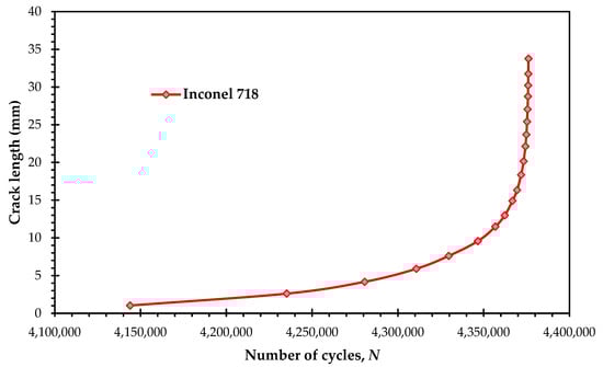
Figure 8.
Predicted fatigue life cycles for Inconel 718.
Figure 9 illustrates that Ti-6Al-4V has substantially the lowest fatigue life among the four materials (e.g., 15,731 cycles). While this might seem to indicate inferior fatigue resistance, a deeper analysis reveals a more nuanced picture. Ti-6Al-4V possesses a high yield strength (828 MPa) and a high modulus of elasticity (114 GPa), contributing to its high safety factor (2.31). This high safety factor suggests that the material is highly resistant to plastic deformation. The relatively high Paris Law exponent ‘m’ (4.1) for Ti-6Al-4V implies that its crack growth rate is highly sensitive to changes in stress intensity. This means that once a crack initiates, it can propagate more rapidly than in Inconel 718, leading to a shorter overall fatigue life despite its excellent elastic properties. However, the previously observed shortest crack length for Ti-6Al-4V under the same load indicates that while it may not endure as many cycles as Inconel 718, it effectively resists significant crack extension, possibly due to its ability to maintain elastic behavior at the crack tip and its high fracture toughness.
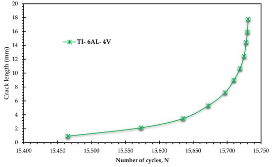
Figure 9.
Predicted fatigue life cycles for Ti-6Al-4V.
Figure 10 clearly shows that Aluminum 7075-T6 has low fatigue compared to Inconel 718 or ASTM A514 Steel (e.g., 33,941 cycles). This performance is consistent with its lower mechanical properties, particularly its yield strength (469 MPa) and modulus of elasticity (71.7 GPa). The very low safety factor (0.56) indicates that this material undergoes significant plastic deformation under the applied cyclic load, leading to rapid crack initiation and propagation. The higher Paris Law coefficient ‘C’ (5.27 × 10⁻¹⁰) and exponent ‘m’ (2.947) further confirm its susceptibility to faster crack growth, making it the least suitable for applications requiring high fatigue resistance under these conditions.
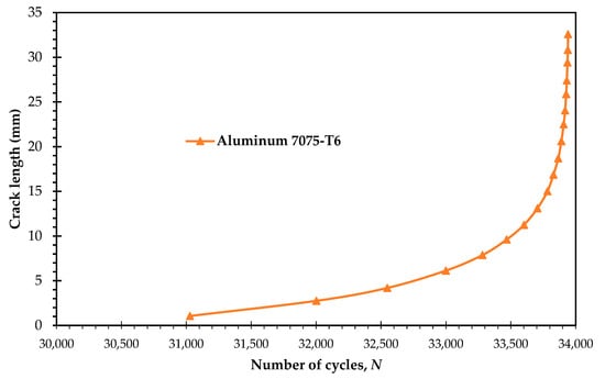
Figure 10.
Predicted fatigue life cycles for Aluminum 7075-T6.
In addition, the fatigue life cycles of the ASTM A514 Steel, also depicted in Figure 11, demonstrates a moderate fatigue life (e.g., 39,870 cycles). Its mechanical properties, including a yield strength of 690 MPa and a modulus of elasticity of 200 GPa, contribute to its better performance compared to Aluminum 7075-T6. The safety factor (0.94) suggests that localized yielding may occur at the crack tip, which can contribute to crack propagation. Its Paris Law constants (C = 5 × 10⁻¹¹, m = 3.5) indicate a crack growth behavior that is more favorable than Aluminum 7075-T6 but not as resistant as Inconel 718.
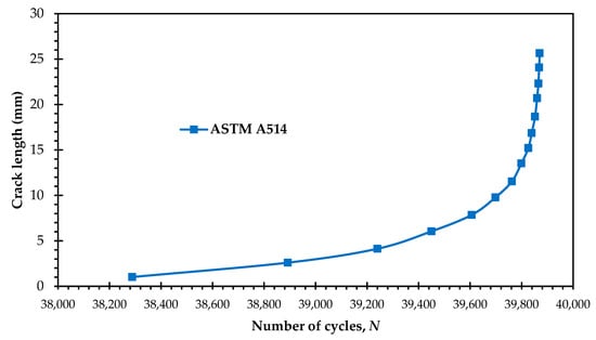
Figure 11.
Predicted fatigue life cycles for ASTM A514 Steel.
Table 3 presents the predicted values of KI, KII, and the corresponding fatigue life cycles for each of the four metallic alloys at key crack propagation stages. This summary aims to illustrate the evolution of these critical fracture mechanics parameters throughout the fatigue life, offering a more detailed insight into the simulation results.
Table 3.
Predicted stress intensity factors and fatigue life cycles for metallic alloys at key crack propagation stages.
Figure 8, Figure 9, Figure 10 and Figure 11, which individually show the fatigue life cycles for four different metals, were combined into a single plot in Figure 12. This consolidated figure uses a semi-log scale, which effectively highlights the differences in fatigue crack growth performance and propagation rates among the alloys. The semi-log scale makes it easier to visually compare their overall fatigue lives and interpret the variations in their behavior. This combined representation offers a more direct and efficient comparison than analyzing each figure separately.
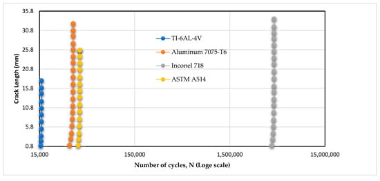
Figure 12.
Combined fatigue life cycles of four metals on a semi-log scale.
Figure 13 provides a visual, step-by-step representation of the simulated fatigue crack propagation path within the specimen, with the predicted crack growth path based on the maximum circumferential stress theory, as represented in Equation (1). The sequence begins at the top-left panel, where the analysis starts with a pre-existing notch. As the simulation progresses, a crack initiates from the sharp tip of this notch and begins to propagate horizontally across the specimen. The subsequent panels clearly illustrate the crack’s trajectory, showing its gradual deviation from a straight path as it advances. In the final stages, depicted in the bottom row, the crack path curves significantly downwards, drawn towards the stress concentration field of the circular hole. The color contours surrounding the crack tip represent the stress intensity, which visibly increases as the crack approaches the hole, culminating in the final panel where the crack is about to penetrate the hole’s boundary.
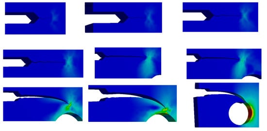
Figure 13.
Crack Growth Trajectory: A Step-by-Step Simulation.
The findings of this study are directly relevant to the specific high-performance metallic alloys investigated, namely Inconel 718, Ti-6Al-4V, Aluminum 7075-T6, and ASTM A514 Steel under the precise loading conditions simulated. It is important to contextualize these results. The focus of the analysis was a comparative study of fatigue crack growth behavior among these conventional materials, rather than an exploration into novel or emerging material categories. Therefore, the conclusions drawn are most accurately applied to engineering scenarios involving these specific alloys and similar stress states. Extrapolating these results to other materials or significantly different loading conditions should be done with caution, as material-specific behaviors like crack initiation and propagation can vary widely.
4. Conclusions
This study successfully utilized finite element analysis, specifically the SMART crack growth feature in ANSYS Mechanical, to conduct a comprehensive parametric investigation into the FCG behavior of four high-performance crystalline metallic alloys: Inconel 718 (Aged), Ti-6Al-4V, Aluminum 7075-T6, and ASTM A514 Steel. The research systematically quantified the impact of key material parameters: Paris Law constants (C and m), yield strength, and modulus of elasticity on critical fatigue performance indicators such as fatigue life cycles, equivalent stress intensity factors, safety factors, von Mises stress, and strain energy.
The findings demonstrate that while all materials exhibit classic Paris Law behavior, their unique combinations of properties lead to a distinct fatigue life hierarchy, with Inconel 718 exhibiting the longest fatigue life, followed by ASTM A514 Steel, Aluminum 7075-T6, and finally Ti-6Al-4V. The present study quantifies the sensitivity of FCG to changes in key material parameters for each alloy. This allows designers to understand which material properties are most critical for fatigue resistance in a given material and how variations in these properties might affect the component’s lifespan. The observed differences in total deformation, von Mises stress distribution, and strain energy further elucidated the distinct responses of each material to cyclic loading. Ultimately, this work contributes to a more robust, data-driven framework for material selection in demanding engineering applications where fatigue life is a paramount design consideration. Future work will focus on integrating experimental validation for Inconel 718, Ti-6Al-4V, and ASTM A514 Steel, and will also explore multi-scale modeling to better incorporate microstructural effects for a more comprehensive understanding of fatigue crack growth.
Author Contributions
Conceptualization, A.M.A.; Methodology, Y.A.F.; Software, A.M.A.; Validation, A.M.A.; Formal analysis, Y.A.F. and A.M.A.; Investigation, Y.A.F. and A.M.A.; Resources, Y.A.F. and A.M.A.; Data curation, A.M.A.; Writing—original draft, A.M.A.; Writing—review & editing, A.M.A.; Visualization, A.M.A.; Supervision, Y.A.F. and A.M.A.; Project administration, Y.A.F. and A.M.A.; Funding acquisition, Y.A.F. and A.M.A. All authors have read and agreed to the published version of the manuscript.
Funding
The authors gratefully acknowledge the funding of the Deanship of Graduate Studies and Scientific Research, Jazan University, Saudi Arabia, through Project number: JU-20250230-DGSSR-RP-2025.
Data Availability Statement
The original contributions presented in this study are included in the article. Further inquiries can be directed to the corresponding author.
Conflicts of Interest
The authors declare no conflicts of interest.
References
- Tavares, S.M.O.; de Castro, P.M.S.T. An overview of fatigue in aircraft structures. Fatigue Fract. Eng. Mater. Struct. 2017, 40, 1510–1529. [Google Scholar] [CrossRef]
- Stephens, R.I.; Fatemi, A.; Stephens, R.R.; Fuchs, H.O. Metal Fatigue in Engineering; John Wiley & Sons: Hoboken, NJ, USA, 2000. [Google Scholar]
- Manson, S.S.a.H.; Gary, R. Fatigue and Durability of Structural Materials; Asm International: Almere, The Netherlands, 2006. [Google Scholar]
- Younis, H.B.; Kamal, K.; Sheikh, M.F.; Hamza, A. Prediction of fatigue crack growth rate in aircraft aluminum alloys using optimized neural networks. Theor. Appl. Fract. Mech. 2022, 117, 103196. [Google Scholar] [CrossRef]
- Shiraiwa, T.; Briffod, F.; Enoki, M. Prediction of fatigue crack initiation of 7075 aluminum alloy by crystal plasticity simulation. Materials 2023, 16, 1595. [Google Scholar] [CrossRef]
- Alshoaibi, A.M.; Bashiri, A.H. Fatigue Crack Growth Studies under Mixed-Mode Loading in AISI 316 Stainless Steel. Appl. Sci. 2023, 13, 9446. [Google Scholar] [CrossRef]
- Smith, G.D.; Baker, B.A. Nickel and its Alloys. Mater. Mech. Des. 2006, 1, 256–277. [Google Scholar]
- Gruber, K.; Szymczyk-Ziółkowska, P.; Dziuba, S.; Duda, S.; Zielonka, P.; Seitl, S.; Lesiuk, G. Fatigue crack growth characterization of Inconel 718 after additive manufacturing by laser powder bed fusion and heat treatment. Int. J. Fatigue 2023, 166, 107287. [Google Scholar] [CrossRef]
- Connolley, T.; Starink, M.; Reed, P. Effect of oxidation on high temperature fatigue crack initiation and short crack growth in Inconel 718. Superalloys 2000, 5, 435–444. [Google Scholar]
- Song, Z.; Gao, W.; Wang, D.; Wu, Z.; Yan, M.; Huang, L.; Zhang, X. Very-high-cycle fatigue behavior of Inconel 718 alloy fabricated by selective laser melting at elevated temperature. Materials 2021, 14, 1001. [Google Scholar] [CrossRef]
- Choudhary, S.; Gaur, V. Improved properties of additively prepared Inconel 718 alloy post-processed with a new heat treatment. Mater. Sci. Eng. A 2024, 911, 146930. [Google Scholar] [CrossRef]
- Zhong, L.; Hu, H.; Liang, Y.; Huang, C. High cycle fatigue performance of inconel 718 alloys with different strengths at room temperature. Metals 2018, 9, 13. [Google Scholar] [CrossRef]
- Ajay, P.; Dabhade, V.V. Heat treatments of Inconel 718 nickel-based superalloy: A Review. Met. Mater. Int. 2024, 31, 1–28. [Google Scholar] [CrossRef]
- Neikter, M.; Colliander, M.; de Andrade Schwerz, C.; Hansson, T.; Åkerfeldt, P.; Pederson, R.; Antti, M.-L. Fatigue crack growth of electron beam melted Ti-6Al-4V in high-pressure hydrogen. Materials 2020, 13, 1287. [Google Scholar] [CrossRef]
- Kalluri, S. Characterization of Fatigue Crack Initiation and Propagation in Ti-6Al-4V with Electrical Potential Drop Technique; National Aeronautics and Space Administration: Washington, WA, USA, 1988; Volume 100877. [Google Scholar]
- Nakatani, M.; Masuo, H.; Tanaka, Y.; Murakami, Y. Effect of surface roughness on fatigue strength of Ti-6Al-4V alloy manufactured by additive manufacturing. Procedia Struct. Integr. 2019, 19, 294–301. [Google Scholar] [CrossRef]
- Wu, Y.; He, W.; Ma, H.; Nie, X.; Liang, X.; Pan, J.; Wang, S.; Shang, M.; Cheng, L. Titanium alloy materials with very high cycle fatigue: A review. Materials 2024, 17, 2987. [Google Scholar] [CrossRef]
- Fu, R.; Ling, C.; Zheng, L.; Zhong, Z.; Hong, Y. Continuum damage mechanics-based fatigue life prediction of L-PBF Ti-6Al-4V. Int. J. Mech. Sci. 2024, 273, 109233. [Google Scholar] [CrossRef]
- Johnsen, A.R.; Petersen, J.E.; Pedersen, M.M.; Yıldırım, H.C. Factors affecting the fatigue strength of additively manufactured Ti-6Al-4V parts. Weld. World 2024, 68, 361–409. [Google Scholar] [CrossRef]
- Rutto, R.; Obara, C.; Harrison, S. Investigation of fatigue cracking in aluminium 7075 alloys and the role of heat treatment. Adv. Mater. Process. Technol. 2024, 10, 3700–3723. [Google Scholar] [CrossRef]
- Zichil, V.; Grigoras, C.C.; Ciubotariu, V.A. Notches and Fatigue on Aircraft-Grade Aluminium Alloys. Materials 2024, 17, 4639. [Google Scholar] [CrossRef]
- Xie, C.; Sun, T.; Li, L.; Zheng, Z. Effect of Microstructure on Fatigue Damage Accumulation in 7075 Aluminum Alloy Subjected to a Single Compressive Overload. Metals 2024, 14, 980. [Google Scholar] [CrossRef]
- Alssayegh, A.; Abdellah, M.Y.; Hassan, M.K.; Azam, S.; Melaibari, A.; Khashaba, U. Optimizing high cycle fatigue predictions in notched Al 7075-T6: An analytical approach to rotating bending behavior. Results Eng. 2025, 25, 103623. [Google Scholar] [CrossRef]
- Schichtel, J.; Datta, S.; Chattopadhyay, A. Study of crack initiation and failure mechanisms in Al 7075 T6 alloy under ultrasonic fatigue. In Proceedings of the AIAA Scitech 2021 Forum, Nashville, TN, USA, 11–15, 19–21 January 2021; p. 1275. [Google Scholar]
- Hunt, E.M. Crack Initiation and Growth Behavior at Corrosion Pit in 7075-T6 High Strength Aluminum Alloy. Master’s Thesis, AFIT, Wright-Patterson AFB, OH, USA, 2013. Available online: https://scholar.afit.edu/etd/829 (accessed on 8 September 2025).
- Gdoutos, E.; Konsta-Gdoutos, M. Fatigue and Environment-Assisted Testing. In Mechanical Testing of Materials; Springer: Berlin/Heidelberg, Germany, 2024; pp. 125–154. [Google Scholar]
- Ince, A. Computational crack propagation modeling of welded structures under as-welded and high frequency mechanical impact (HFMI) treatment conditions. Fatigue Fract. Eng. Mater. Struct. 2022, 45, 578–592. [Google Scholar] [CrossRef]
- Kyekyere, E.; Olakanmi, E.; Prasad, R.; Matshediso, B.; Motimedi, T.; Botes, A.; Pityana, S. Analysis of failure characteristics of screen plates of ring hammer crusher used in coal handling applications. Eng. Fail. Anal. 2024, 162, 108351. [Google Scholar] [CrossRef]
- Barsom, J. Fatigue-crack growth under variable-amplitude loading in ASTM A514-B steel. In Progress in Flaw Growth and Fracture Toughness Testing; ASTM International: West Conshohocken, PA, USA, 1973. [Google Scholar] [CrossRef]
- Connor, R.J.; Lloyd, J.B. Maintenance Actions to Address Fatigue Cracking in Steel Bridge Structures; Purdue University: West Lafayette, IN, USA, 2017. [Google Scholar]
- Suresh, S. Fatigue of Materials, 2nd ed.; Cambridge University Press: Cambridge, UK, 1998. [Google Scholar] [CrossRef]
- Alshoaibi, A.M. Computational Simulation of 3D Fatigue Crack Growth under Mixed-Mode Loading. Appl. Sci. 2021, 11, 5953. [Google Scholar] [CrossRef]
- Alshoaibi, A.M. Fatigue Crack Growth Analysis in Modified Compact Tension Specimen with Varying Stress Ratios: A Finite Element Study. Appl. Sci. 2023, 13, 13160. [Google Scholar] [CrossRef]
- Alshoaibi, A.M.; Fageehi, Y.A. Numerical analysis of fatigue crack growth path and life predictions for linear elastic material. Materials 2020, 13, 3380. [Google Scholar] [CrossRef]
- Alshoaibi, A.M.; Fageehi, Y.A. Numerical Analysis on Fatigue Crack Growth at Negative and Positive Stress Ratios. Materials 2023, 16, 3669. [Google Scholar] [CrossRef] [PubMed]
- Bjørheim, F. Practical Comparison of Crack Meshing in ANSYS Mechanical APDL 19.2; University of Stavanger: Stavanger, Norway, 2019. [Google Scholar]
- ANSYS. Academic Research Mechanical, Release 19.2, Help System. In Coupled Field Analysis Guide; ANSYS, Inc.: Canonsburg, PA, USA, 2020. [Google Scholar]
- Kebir, T.; Benguediab, M.; Imad, A. A model for fatigue crack growth in the paris regime under the variability of cyclic hardening and elastic properties. Fatigue Aircr. Struct. 2017, 2017, 117–135. [Google Scholar] [CrossRef]
- Xiangqiao, Y.; Shanyi, D.; Zehua, Z. Mixed-mode fatigue crack growth prediction in biaxially stretched sheets. Eng. Fract. Mech. 1992, 43, 471–475. [Google Scholar] [CrossRef]
- Giner, E.; Sukumar, N.; Tarancón, J.; Fuenmayor, F. An Abaqus implementation of the extended finite element method. Eng. Fract. Mech. 2009, 76, 347–368. [Google Scholar] [CrossRef]
- Fageehi, Y.A.; Alshoaibi, A.M. Enhancing Fatigue Life Prediction Accuracy: A Parametric Study of Stress Ratios and Hole Position Using SMART Crack Growth Technology. Crystals 2025, 15, 596. [Google Scholar] [CrossRef]
- Denny, J.; Jinoop, A.; Paul, C.; Singh, R.; Bindra, K. Fatigue crack propagation behaviour of inconel 718 structures built using directed energy deposition based laser additive manufacturing. Mater. Lett. 2020, 276, 128241. [Google Scholar] [CrossRef]
- Majchrowicz, K.; Chmielewska, A.; Wysocki, B.; Przybysz-Gloc, S.; Kulczyk, M.; Garbacz, H.; Pakieła, Z. The Effect of Microstructural Defects on High-Cycle Fatigue of Ti Grade 2 Manufactured by PBF-LB and Hydrostatic Extrusion. Crystals 2023, 13, 1250. [Google Scholar] [CrossRef]
- Soni, S. Numerical Modelling of Crack Growth Path in Linear Elastic Materials. In Fracture Behavior of Nanocomposites and Reinforced Laminate Structures; Springer: Berlin/Heidelberg, Germany, 2024; pp. 157–172. [Google Scholar]
- Cheng, Z.; Wang, H. A novel X-FEM based fast computational method for crack propagation. arXiv 2017, arXiv:1708.01610. [Google Scholar] [CrossRef]
- Jafari, A.; Broumand, P.; Vahab, M.; Khalili, N. An eXtended finite element method implementation in COMSOL multiphysics: Solid mechanics. Finite Elem. Anal. Des. 2022, 202, 103707. [Google Scholar] [CrossRef]


Disclaimer/Publisher’s Note: The statements, opinions and data contained in all publications are solely those of the individual author(s) and contributor(s) and not of MDPI and/or the editor(s). MDPI and/or the editor(s) disclaim responsibility for any injury to people or property resulting from any ideas, methods, instructions or products referred to in the content. |
© 2025 by the authors. Licensee MDPI, Basel, Switzerland. This article is an open access article distributed under the terms and conditions of the Creative Commons Attribution (CC BY) license (https://creativecommons.org/licenses/by/4.0/).