Abstract
This study introduces an improved X-shaped re-entrant auxetic structure designed to enhance mechanical performance by incorporating diamond-shaped elements into the re-entrant hexagonal configuration. Using a validated numerical model, the resistance of sandwich beams with the proposed core under localized impulsive loading is explored. The results reveal that local compression and global shear deformation dominate the response. The study further examines the effects of cell arrangement, geometric parameter, inclined gradient distribution, and cell construction on structural behavior. The X-direction arrangement of cells significantly enhances deformation control, improving deflection by dissipating impact energy. Increasing the angle α enhances mechanical properties and reduces residual deflection. Various inclined gradient distribution designs notably affect performance: positive gradients improve energy absorption, while negative gradients alter deformation mode. Under the same conditions, the proposed sandwich beam outperforms the conventional re-entrant hexagonal sandwich beam in terms of impact resistance. This research offers valuable insights for the design of explosion-resistant metamaterial sandwich structures.
1. Introduction
Compared to traditional monolithic structures, sandwich structures exhibit superior properties such as low weight, high specific strength, high specific stiffness, excellent energy absorption, and remarkable impact resistance [1,2,3]. These advantages make sandwich structure an ideal choice for protective applications, particularly in the aerospace, vessel, and vehicle industries [4,5]. A typical sandwich structure consists of two high-performance panels and a lightweight core, with the core positioned between the panels. To enhance structural impact resistance, altering the core configuration offers more flexibility than merely increasing thickness or using alternative materials.
Lightweight cores can be classified based on their deformation behavior under transverse tension: traditional cores with a positive Poisson’s ratio [6] and auxetic cores with a negative Poisson’s ratio [7,8,9]. Auxetic structures expand longitudinally when subjected to transverse tension. Due to this unique behavior, auxetic structures exhibit superior macroscopic mechanical properties, such as enhanced indentation resistance [10] and energy absorption capacity [11,12], compared to traditional cores. Common auxetic structures typically include re-entrant and double-arrow configurations [1,7], as well as rotating polygon, chiral, and anti-chiral lattices [13,14,15]. These classes represent fundamental approaches to achieving a negative Poisson’s ratio through geometry rather than material properties. Since the pioneering works of Lakes [16] and Evans [17], auxetic materials have been extensively studied for applications requiring enhanced toughness and impact resistance. Following these foundational contributions, several comprehensive reviews [18,19] have provided systematic summaries of auxetic materials and structures, focusing on their deformation mechanisms and multifunctional application prospects.
Based on this background, the behavior of auxetic sandwich structures has been widely studied. Yang et al. [20] and Qi et al. [21] performed numerical simulations on the ballistic impact performance of sandwich structures, finding that auxetic cores provide better ballistic resistance than traditional cores. Grujicic et al. [22] explored the deformation and failure modes of auxetic cores, while Imbalzano et al. [23] reported that auxetic sandwich panels more effectively absorb and reduce transmitted energy than conventional honeycomb panels. Beyond idealized configurations, recent work also emphasized the role of geometric imperfections and manufacturing-induced irregularities, which can significantly influence stiffness, strength, and energy absorption [24]. These studies confirm the superior impact resistance of auxetic cores and highlight the practical importance of accounting for imperfections in design and analysis.
Further performance improvements in sandwich structures have been explored. Xiao et al. [25,26] studied the dynamic response of sandwich beams and arches with re-entrant cores under local impact loads, identifying three primary failure modes. Liu et al. [27] introduced a novel three-dimensional bionic cell design, demonstrating improved impact resistance and energy absorption compared to traditional re-entrant hexagonal design. Lan et al. [28] compared the impact resistance of sandwich arches with auxetic, hexagonal, and foam aluminum cores under explosive loading, confirming the superior performance of auxetic cores. Their study also found that increasing curvature and panel thickness enhances the blast resistance of sandwich structures. Smaller cell aspect ratios and length ratios were shown to amplify the negative Poisson’s ratio effect, further improving blast resistance. Lin et al. [29] developed a concave arc-shaped sandwich panel, which outperformed re-entrant auxetic and double-arrow structures in blast resistance. Their further research indicated that positive gradient and curved wall designs improve anti-blast performance. Pang et al. [30] examined the effect of loading direction on structures’ mechanical performance, finding that quasi-static loading in the Y-direction yielded better results. Li et al. [31] introduced a design with diamond-shaped structures added to the re-entrant hexagonal structure and demonstrated that this new design significantly improved load-carrying and energy absorption capabilities. Overall, auxetic cores significantly enhance the mechanical performance of sandwich structures.
Gradient design, often implemented through variations in porosity, can be achieved by adjusting cell-wall thickness, density [32,33,34,35], material composition [36], microstructure [37], or geometric parameters [38]. As research deepens, the benefits of gradient design in core structures have become evident. Shen et al. [39] studied the deformation of hexagonal honeycombs with material yield stress gradients under compressive loading and found that positive gradient designs enhance energy absorption under low-velocity compression. Xiao et al. [40] investigated the compressive deformation behavior of re-entrant structures with wall thickness gradients, revealing that bidirectional gradient distributions yield higher plateau stress and better energy dissipation compared to unidirectional gradients. Zhang et al. [41] developed a re-entrant anti-trichiral structure with gradient distributions for key parameters, demonstrating superior elastic stiffness, energy absorption, and densification strain over homogeneous designs. These findings confirm that gradient design can improve mechanical properties and alter deformation modes.
Although considerable efforts have been made to optimize the mechanical performance of sandwich cores, the development of new auxetic structures and their systematic design optimization remain necessary. To enhance the mechanical performance of re-entrant cores, previous experimental and numerical studies [42] incorporated diamond-shaped elements into the horizontal walls of the re-entrant cells, proposing an improved auxetic design. Compared with conventional re-entrant structures, these diamond-shaped substructures enhance structural stability, enable the formation of new configurations during compression, and generate multi-stage deformation modes with dual-plateau stress responses under in-plane compression.
Building on this design, the present study integrates the X-shaped auxetic core into sandwich beams and evaluates their impact resistance under local impulsive loading using a validated numerical model, revealing the dynamic response of the structures. The effects of cell arrangement and geometric parameters are systematically investigated, and unconventional inclined gradient distributions of wall thickness are examined to understand their influence on mechanical performance. Finally, sandwich beams with different core configurations are compared to assess the effects of cell design on overall structural behavior.
2. Structural Design
An improved X-shaped re-entrant auxetic structure (XAH) is developed by incorporating diamond elements into the horizontal walls of a traditional re-entrant auxetic configuration (RAH), as illustrated in Figure 1. The sandwich beam consists of an XAH core and two panels, with both the front and back panels having identical thicknesses (hf = hb = 1 mm). The sandwich beam’s dimensions are defined by its length (L), width (B), and height (H). Here, the width B is fixed at 50 mm, while L and H depend on the arrangement and number of cells. In this study, the beam incorporates cells arranged vertically and horizontally in the sandwich beam, corresponding to dimensions of L = 252 mm and H = 26 mm. The geometric of the X-shaped cell is defined by key parameters: a, b, α, β, t, l, and h. Here, a represents the horizontal bar length of cell, b denotes the diagonal length of the diamond structure, α is the angle between the long inclined bar and the horizontal bar, β is the angle between the inclined bar and the horizontal line, t is the cell-wall thickness, l is the overall length of the unit cell, and h is the overall height of the unit cell. In this study, the parameters are set as a = 12 mm, b = 4 mm, α = β = 45°, t = 0.5 mm, l = 16 mm, and h = 4 mm.


Figure 1.
Schematic diagram of an X-shaped re-entrant auxetic sandwich beam. (a) Improved design concept and (b) dimensions of the sandwich beam.
3. Numerical Simulation
3.1. Establishment of Numerical Model
To evaluate the impact resistance of X-shaped re-entrant auxetic sandwich beams under localized impulsive loading, numerical simulations were conducted using the finite element software ABAQUS/Explicit (Version 6.13). Leveraging the model’s symmetry, only a quarter of the structure was modeled to reduce calculation cost, as illustrated in Figure 2. The foam projectile was modeled using the isotropic hardening constitutive law for crushable foam, with a radius of 18 mm, length of 60 mm, density of 231.86 kg/m3, plateau stress of 1.7 MPa, and densification strain of 0.65. The panels were fabricated from 5052 aluminum alloy, while the core was 3D-printed from AlSi10Mg aluminum alloy powder [25]. Both the panels and core were represented using an ideal rigid-plastic material model that ignores strain-rate effects, with yield strength of 120 MPa and 200 MPa, respectively.
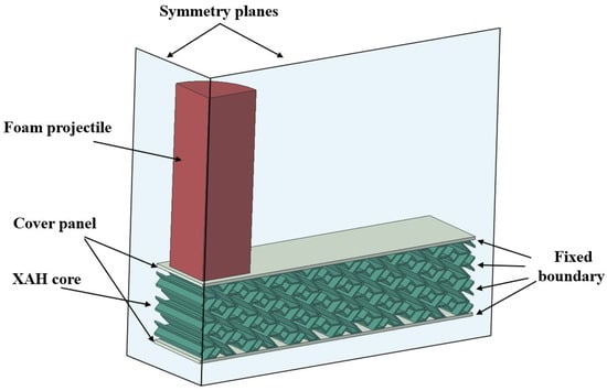
Figure 2.
Finite element model of the X-shaped re-entrant auxetic sandwich beam under foam projectile impact.
Interactions were simulated using surface-to-surface contact between the projectile and panels, while general contact was used for the interfaces between the core and panels, with frictionless tangential and normal hard contact properties. A tie constraint was applied to bond the panels and core. The initial velocity of the aluminum foam projectile was set to 253.23 m/s, based on prior experimental studies [25] to produce sufficient deformation for investigating the dynamic response and energy absorption of the X-shaped re-entrant auxetic sandwich beams. Fixed and symmetry boundary conditions were imposed to represent the clamped ends and symmetric model geometry. The projectile and panels were discretized using eight-node hexahedral linear reduced-integration elements, while the core employed a combination of eight-node hexahedral and six-node triangular prism elements. Mesh sizes of 0.6 mm, 0.8 mm, 1.0 mm, and 1.2 mm were tested, yielding element counts of 27,516, 19,953, 14,388, and 11,754, respectively. Considering the trade-off between computational cost and accuracy, a mesh size of 0.8 mm was selected for subsequent simulations to ensure high precision with manageable computational effort.
3.2. Validation of Numerical Model
Since no prior studies have reported the dynamic response of this proposed auxetic structure, the numerical model developed in this work was validated against a series of experimental results from Ref. [25], as shown in Figure 3. The deformation modes of the beam and the residual deflection of the core layer in numerical simulation #2-1 exhibited a close correspondence with the experimental observations. Table 1 presents a comparison of residual deflections of the beam between the numerical predictions and the experimental data, showing deviations within an acceptable range. These discrepancies primarily stem from the exclusion of cell-wall fracture behavior in the simulations. It should be noted that the validation was performed for conventional re-entrant auxetic structures; the X-shaped variant introduces primarily geometric differences. The validated material models, boundary conditions, and numerical parameters remain applicable to the X-shaped configuration. Moreover, although strain-rate sensitivity is neglected, this simplification does not significantly affect residual deflection predictions for the selected materials, as confirmed by the good agreement with experimental data. Overall, the numerical results display strong agreement with the experimental findings, confirming the reliability of the model. This validated model thus provides a solid foundation for subsequent investigations into the mechanical behavior of the proposed auxetic structure.
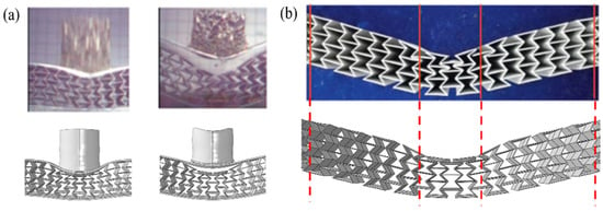
Figure 3.
Comparison of deformation results between experiment [25] and numerical simulation of the re-entrant auxetic sandwich beams. (a) Deformation of the beams when the foam projectile hits the beam (left) and the core becomes separated from the panel (right). (b) Residual deflection of the core layer.

Table 1.
Comparison of residual deflection between numerical simulation and experiment [25] of the re-entrant auxetic sandwich beams under foam projectile impact.
4. Dynamic Response Results
4.1. Deformation Mode
The dynamic response of X-shaped re-entrant auxetic sandwich beams under localized impulsive loading can be divided into three distinct stages—compression, deflection, and rebound—as illustrated in Figure 4.
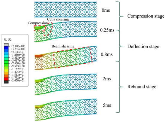
Figure 4.
Deformation process of the X-shaped re-entrant auxetic sandwich beam under foam projectile impact.
Compression Stage (0–0.25 ms): During this phase, the contact force generated by the foam projectile causes local compression of the sandwich beam. The negative Poisson’s ratio effect induces tensile deformation in the midsection, while the projectile impact generates shear forces that produce significant shear deformation near the center of the beam.
Deflection Stage (0.25–0.8 ms): The impact-induced shear stress propagates outward, causing the sandwich beam to deflect. The bonding between the core and panels enhances shear resistance, resulting in reduced shear deformation closer to the fixed ends.
Rebound Stage (0.8–5 ms): Fixed-end constraints cause the beam to rebound and vibrate before eventually coming to rest.
In summary, the residual deflection of the sandwich beam primarily results from compressive and shear deformations of the cells during the compression and deflection stages, with these effects concentrated in the beam’s central region.
4.2. Force–Displacement Curve
Figure 5 illustrates the force–displacement curve of the X-shaped re-entrant auxetic sandwich beam, which predominantly includes the compression and deflection stages due to the short contact duration.

Figure 5.
Typical force–displacement curve of the X-shaped re-entrant auxetic sandwich beam under foam projectile impact.
Compression Stage: The curve initially exhibits a high peak force followed by a fluctuating plateau force, representing the primary load-bearing phase. When the foam projectile impacts the beam at high velocity, it induces fluctuating forces as the projectile undergoes compression and densification. This stage accounts for the majority of energy absorption.
Deflection Stage: The impact stress propagates from the compressed region to the beam’s sides, causing bending and shear deformation within the honeycomb cells. The force exerted on the front panel diminishes at this stage, as much of the projectile’s kinetic energy is converted into strain energy during the compression stage.
5. Discussion
5.1. The Effect of Cell Direction
To investigate the influence of cell arrangement direction, the X-direction and Y-direction cell configurations of the core were analyzed. To ensure consistency in sandwich beam dimensions, the number of cells in the X-direction and Y-direction cores was adjusted to and , accordingly.
The deformation modes of the two sandwich beams, shown in Figure 6, reveal that the X-direction core exhibits greater compression and more pronounced local cell shear, whereas the Y-direction core shows increased overall deflection. Cell arrangement significantly affects the mechanical behavior of the structure. Figure 7 illustrates the residual deflection distribution of the back panel. The central deflection of the back panel with the Y-direction core is 6.7% greater than that with the X-direction core, demonstrating the superior impact resistance of the X-direction configuration.
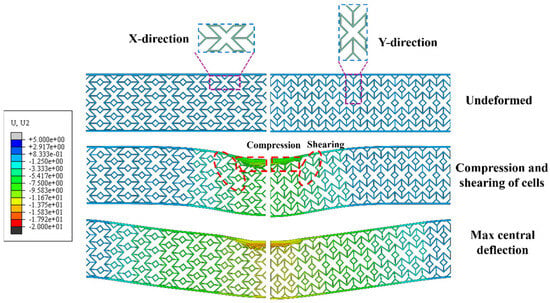
Figure 6.
Comparison of typical deformation modes of the sandwich beams with different cell arrangement directions (colored by displacement magnitude, mm).
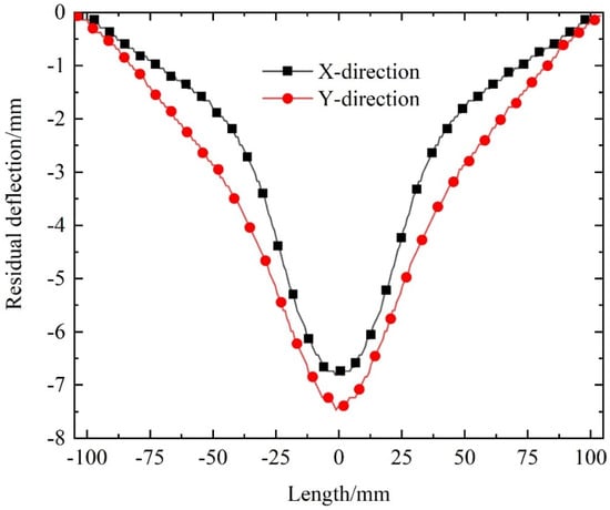
Figure 7.
Comparison of the residual deflection distribution of the back panel of sandwich beams with different cell arrangement directions.
The observed differences in deformation and back-panel deflection between X- and Y-direction cores highlight the anisotropic and partially auxetic nature of the proposed X-shaped structure, consistent with Branka et al. [43], where auxetic behavior can occur only along certain directions. This directional dependence emphasizes that the auxetic response of the structure is not isotropic but varies with cell orientation, which is important for understanding and designing its mechanical performance under different loading conditions.
Specific energy absorption (SEA) is a critical indicator for evaluating structural performance, and is calculated as follows:
where M is the mass of the structure, and EA is the total absorbed energy, defined by
where F(x) represents the external force, and d is the displacement caused by the applied load.
As shown in Figure 8, the difference in EA and SEA between the two sandwich beams is minor. The X-direction core increases EA by 6.4% and SEA by 3.85% compared to the Y-direction core, highlighting the mechanical advantage of the X-direction configuration.
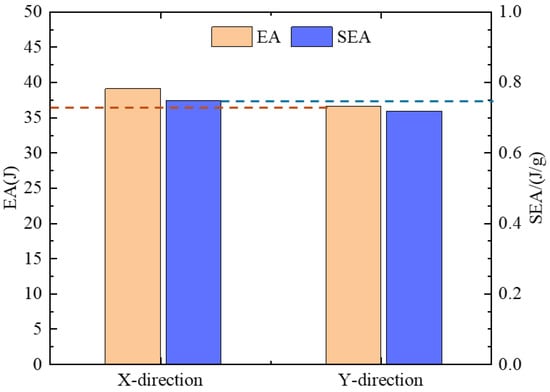
Figure 8.
Comparison of energy absorption of the sandwich beams with different cell arrangements directions.
In summary, the X-direction core dissipates more impact energy through cell deformation, thereby reducing the back panel’s deflection. Conversely, the Y-direction core, with limited deformation capacity, absorbs less energy, leading to greater back-panel deflection under impact.
5.2. The Effect of Geometric Parameter
To investigate the influence of cell geometric parameters on the mechanical performance of the sandwich beam, X-shaped re-entrant auxetic cells with α values of 40°, 45°, 50°, and 55° were designed, as illustrated in Figure 9. This range was chosen to avoid geometric overlap of the re-entrant corners, ensuring structural integrity and manufacturability.

Figure 9.
X-shaped re-entrant auxetic cells with different α angle designs.
Figure 10 shows the deformation modes of X-shaped re-entrant auxetic sandwich beams with varying α angles at maximum deflection of the back panel. The deformation modes appear largely similar across the designs. The residual deflection distribution of the back panel, presented in Figure 11, demonstrates that the back-panel deflection at the same position decreases progressively with an increase in α. Figure 12 shows the central deflection history curves, revealing that the deflection rapidly increases to a maximum, then decreases and stabilizes. Overall, both the maximum and residual central deflections of the back panel diminish as α increases.
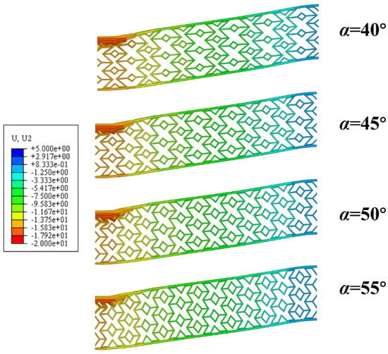
Figure 10.
Comparison of maximum back-panel deflection of sandwich beams with different cell angles (colored by displacement magnitude, mm).
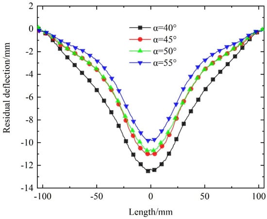
Figure 11.
Comparison of the residual deflection distribution of the back panel of sandwich beam with different cell angle designs.
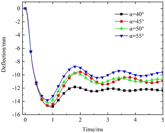
Figure 12.
Comparison of deflection–time curves of the back panel at the center of the sandwich beam with different cell angle designs.
Figure 13 compares the energy absorption capacity of the sandwich beams. The results indicate that the energy absorption performance remains relatively stable with increasing α except for a slight reduction in EA and SEA at α = 55°. This reduction is attributed to the altered proportion of diamond shapes within the cells, which affects structural energy absorption. Considering both deformation and energy absorption, X-shaped re-entrant auxetic sandwich beams with α values of 45° and 50° demonstrate superior impact resistance. Therefore, increasing α within a specific range can effectively reduce the maximum deflection of the back panel and enhance the structural impact resistance.
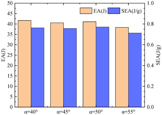
Figure 13.
Comparison of energy absorption of the sandwich beams with different cell angle designs.
5.3. The Effect of Gradient Distribution
Based on the thickness distribution of cell walls, inclined bidirectional gradient structures were designed, as illustrated in Figure 14. These designs are categorized into two types, A-type and B-type, with each type further divided into positive and negative gradient configurations. As a result, four gradient distribution designs and one homogeneous design were considered.
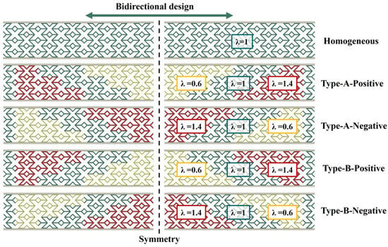
Figure 14.
Schematic diagram of the gradient design for inclined bidirectional thickness gradient sandwich beams.
To ensure reproducibility and comparability, the thickness ratio is defined as follows:
where ti is the local wall thickness at a given position and t0 = 0.5 mm is the wall thickness of the homogeneous configuration. Accordingly, three discrete thickness levels were considered, corresponding to (t = 0.3 mm), (t = 0.5 mm), and (t = 0.7 mm). For the positive gradient design, increases monotonically from 0.6 to 1.4 along the gradient direction, while for the negative gradient design, decreases from 1.4 to 0.6.
Figure 15 depicts the deformation modes of X-shaped re-entrant auxetic sandwich beams with various gradient designs. Gradient structures result in distinct deformation modes. In positive gradient beams, relatively thin walls are located near the upper region, where local buckling and stress concentration are prone to initiate under compression, leading to more pronounced overall compression and shear deformation. In negative gradient beams, the thinner walls are distributed near the lower region, which alters the load transfer pathways and restrains extensive compression deformation in the upper region. Instead, the local instability of the thinner lower walls gives rise to more significant shear deformation. This indicates that the thickness gradient not only influences the global stiffness distribution but also determines the initiation sites of buckling and the dominant stress concentration pathways, thereby governing the distinct deformation behavior of sandwich beams.
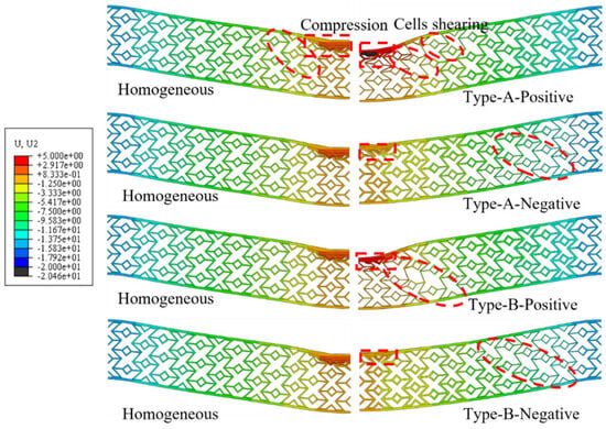
Figure 15.
Comparison of deformation modes of gradient-designed sandwich beams at maximum central deflection of the back panel (colored by displacement magnitude, mm).
The residual deflection distribution of the back panel for different gradient designs is shown in Figure 16. Compared to homogeneous design, the A-type positive gradient design slightly increases the back panel’s residual deflection, while the B-type positive gradient design slightly decreases it. Notably, the deflection distributions of these three configurations are similar. Conversely, the deflection distributions of beams with negative gradient designs are larger overall. Figure 17 presents the central deflection history of the back panel. While positive gradient designs increase the maximum central deflection, they result in smaller residual deflections. On the other hand, negative gradient designs reduce the maximum deflection but lead to greater residual deflections. Additionally, the B-type positive gradient design shows a slight performance advantage over the A-type.
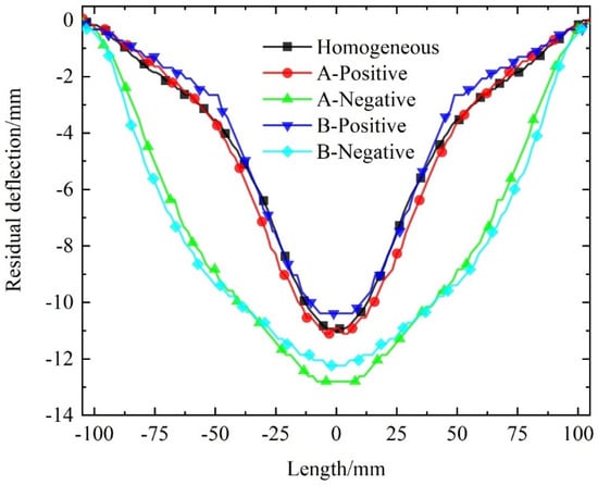
Figure 16.
Comparison of residual deflection distribution of the back panel of sandwich beams with different gradient designs.
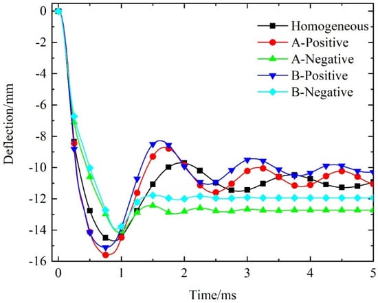
Figure 17.
Comparison of central deflection–time curve of the back panel of the sandwich beams with different gradient designs.
Figure 18 compares the energy absorption (EA) and specific energy absorption (SEA) of sandwich beams with different gradient designs. Beams with positive gradient designs exhibit higher EA and SEA values than the homogeneous design, whereas negative gradient designs reduce both metrics. Considering both total energy absorption and the influence of structural mass, these results indicate that positive gradient designs not only enhance the absolute energy absorption, but also improve the energy absorption efficiency of X-shaped re-entrant auxetic sandwich beams.
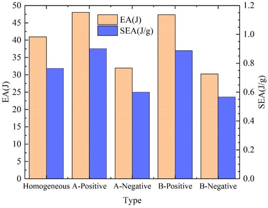
Figure 18.
Comparison of energy absorption of sandwich beams with different gradient designs.
Overall, the findings indicate that inclined gradient designs improve structural response. Positive gradient designs enhance energy absorption and reduce residual deflections, while negative gradient designs primarily alter the deformation modes, offering potential applications in tailored mechanical responses.
5.4. The Effect of Cell Construction
To investigate the effect of cell design improvements, the dynamic response of X-shaped re-entrant auxetic (XAH) sandwich beams was compared to that of traditional re-entrant auxetic (RAH) sandwich beams, both with identical cell-wall thickness. Figure 19 illustrates the deformation modes of the two sandwich beams, showing similar behaviors characterized by cell compression and overall beam bending deformation. The residual deflection curves of the back panel, presented in Figure 20, reveal that the XAH sandwich beam exhibits reduced residual deflection compared to the RAH counterpart.
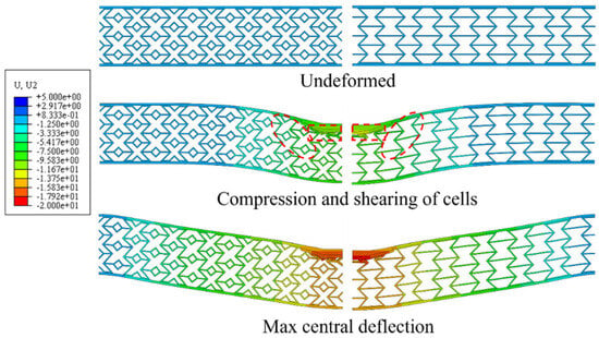
Figure 19.
Comparison of typical deformation modes of sandwich beams with different cell constructions (colored by displacement magnitude, mm).
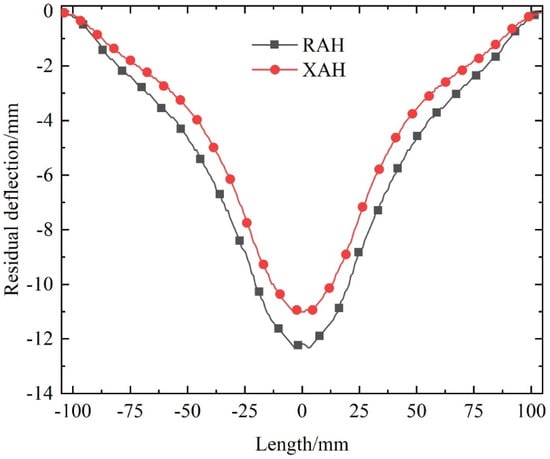
Figure 20.
Comparison of maximum deflection distribution of the back panel of sandwich beams with different cell constructions.
As shown in Figure 21, the XAH sandwich beam achieves a 4.48% reduction in maximum central deflection of the back panel, along with improved residual deflection, indicating enhanced deformation resistance under identical wall thickness. Figure 22 compares the energy absorption (EA) and specific energy absorption (SEA) of the two sandwich beam designs. Although the EA of the RAH sandwich beam is only 8.81% higher than that of the XAH design, its SEA is significantly greater, increasing by 28.5% when accounting for structural mass. These findings suggest that incorporating diamond-shaped structures into the RAH core enhances deformation resistance in sandwich structures but compromises energy absorption performance.
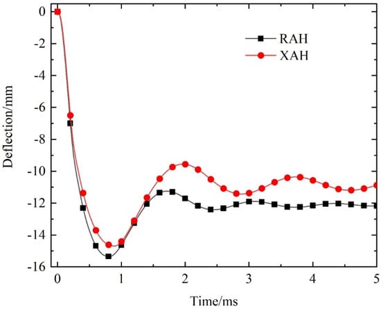
Figure 21.
Comparison of deflection–time curves at the center of the back panel of the sandwich beams with different cell constructions.
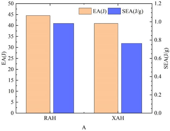
Figure 22.
Comparison of energy absorption of sandwich beams with different cell constructions.
6. Conclusions
In this study, an improved X-shaped re-entrant auxetic structure (XAH) was proposed, and the mechanical performance of sandwich beams incorporating this core was investigated under metal foam projectile impact. Reliable numerical models were established and validated against experimental data. The influence of cell arrangement direction, geometric parameter, inclined gradient design, and cell construction on the sandwich beam’s impact performance was systematically analyzed. The main conclusions are summarized as follows:
- (1)
- The dynamic response of XAH sandwich beams under foam projectile impact can be divided into three stages: localized compression in the central region, global deflection of the beam, and free vibration during the rebound phase. The predominant failure modes are compression and shear deformation during the compression and deflection stages.
- (2)
- Sandwich beams with X-direction cores exhibit superior impact resistance, absorbing more energy through cell compression and reducing back-panel deflection compared to beams with Y-direction cores, which demonstrate weaker performance in both impact resistance and energy absorption.
- (3)
- Increasing the cell angle α from 40° to 55° can enhance the beam’s impact resistance and reduce back-panel deflection, albeit with a trade-off in reduced energy absorption capacity.
- (4)
- The inclined gradient design significantly influences mechanical performance. Positive gradient designs enhance energy absorption and reduce residual deflection, while negative gradient designs alter deformation modes to emphasize bending and reduce maximum central deflection at the cost of higher residual deflection.
- (5)
- Compared to traditional re-entrant auxetic structures (RAH), the XAH structure improves deformation resistance but reduces energy absorption, highlighting a design trade-off: XAH cores are preferable when minimal residual deflection is desired, whereas RAH cores are better for maximizing energy absorption.
Building on these findings, future work can further explore the applicability of the XAH design through experimental testing, strain-rate sensitive modeling, and optimization of cell angle α and gradient parameters, providing guidance for practical design applications. In addition, incorporating suitable filler materials into the cell voids could be investigated to further enhance stiffness, energy absorption, and impact resistance.
Author Contributions
Conceptualization, W.Z. and H.W.; methodology, W.Z.; software, T.Q.; validation, T.Q.; formal analysis, W.Z.; investigation, T.Q. and H.W.; resources, X.C., X.L. and J.S.; data curation, T.Q.; writing—original draft preparation, T.Q.; writing—review and editing, W.Z.; visualization, T.Q.; supervision, J.S.; project administration, W.Z.; funding acquisition, W.Z. and X.L. All authors have read and agreed to the published version of the manuscript.
Funding
This research was funded by National Natural Science Foundation of China, grant number 12102193, Opening project of Hubei Province Key Laboratory of Systems Science in Metallurgical Process (Wuhan University of Science and Technology), grant number Y202408, and Opening project of State Key Laboratory of Precision Blasting and Hubei Key Laboratory of Blasting Engineering (Jianghan University), grant number PBSKL2023B11.
Data Availability Statement
Data is contained within the article.
Acknowledgments
The authors are grateful for financial supports of National Natural Science Foundation of China (No. 12102193), Opening projects of Hubei Province Key Laboratory of Systems Science in Metallurgical Process (Wuhan University of Science and Technology, No. Y202408), and State Key Laboratory of Precision Blasting and Hubei Key Laboratory of Blasting Engineering (Jianghan University, No. PBSKL2023B11).
Conflicts of Interest
The authors declare no conflicts of interest.
References
- Wang, H.; Shao, J.; Zhang, W.; Yan, Z.; Huang, Z.; Liang, X. Three-point bending response and energy absorption of novel sandwich beams with combined re-entrant double-arrow auxetic honeycomb cores. Compos. Struct. 2023, 326, 117606. [Google Scholar] [CrossRef]
- Zhang, W.; Qin, Q.; Li, K.; Li, J.; Wang, Q. Effect of stepwise gradient on dynamic failure of composite sandwich beams with metal foam core subject to low-velocity impact. Int. J. Solids Struct. 2021, 228, 111125. [Google Scholar] [CrossRef]
- Zhang, W.; Qin, Q.; Li, J.; Li, K.; Poh, L.; Li, Y.; Zhang, J.; Xie, S.; Chen, H.; Zhao, J. Deformation and failure of hybrid composite sandwich beams with a metal foam core under quasi-static load and low-velocity impact. Compos. Struct. 2020, 242, 112175. [Google Scholar] [CrossRef]
- Birman, V.; Kardomateas, G.A. Review of current trends in research and applications of sandwich structures. Compos. Part B Eng. 2018, 142, 221–240. [Google Scholar] [CrossRef]
- Metschkow, B. Sandwich panels in shipbuilding. Pol. Martime Res. 2006, 13, 5–8. [Google Scholar]
- Gibson, L.J.; Ashby, M.F.; Schajer, G.S.; Robertson, C.I. The mechanics of two-dimensional cellular materials. Proc. R. Soc. Lond. A Math. Phys. Sci. 1982, 382, 25–42. [Google Scholar]
- Zhang, W.; Wang, H.; Lou, X.; Yan, Z.; Shao, J.; Wu, T.; Qin, Q. On in-plane crushing behavior of a combined re-entrant double-arrow honeycomb. Thin-Walled Struct. 2024, 194, 111303. [Google Scholar] [CrossRef]
- Xu, C.; Li, Q.; Zhang, L.; Liu, Q.; Ren, L. Glass Sponge-inspired Auxetic Mechanical Metamaterials for Energy Absorption. J. Bionic Eng. 2024, 21, 2349–2365. [Google Scholar] [CrossRef]
- Lakes, R.; Wojciechowski, K.W. Negative compressibility, negative Poisson’s ratio, and stability. Phys. Status Solidi (B) 2008, 245, 545–551. [Google Scholar] [CrossRef]
- Photiou, D.; Prastiti, N.; Sarris, E.; Constantinides, G. On the conical indentation response of elastic auxetic materials: Effects of Poisson’s ratio, contact friction and cone angle. Int. J. Solids Struct. 2016, 81, 33–42. [Google Scholar] [CrossRef]
- Qi, C.; Remennikov, A.; Pei, L.-Z.; Yang, S.; Yu, Z.-H.; Ngo, T.D. Impact and close-in blast response of auxetic honeycomb-cored sandwich panels: Experimental tests and numerical simulations. Compos. Struct. 2017, 180, 161–178. [Google Scholar] [CrossRef]
- Jin, X.; Wang, Z.; Ning, J.; Xiao, G.; Liu, E.; Shu, X. Dynamic response of sandwich structures with graded auxetic honeycomb cores under blast loading. Compos. Part B Eng. 2016, 106, 206–217. [Google Scholar] [CrossRef]
- Wojciechowski, K.W. Two-dimensional isotropic system with a negative Poisson ratio. Phys. Lett. A 1989, 137, 60–64. [Google Scholar] [CrossRef]
- Grima, J.N.; Evans, K.E. Auxetic behavior from rotating squares. J. Mater. Sci. Lett. 2000, 19, 1563–1565. [Google Scholar] [CrossRef]
- Lim, T.C. Auxetic Metamaterial Model Made from Rotating Rectangles, Hexagons, and Triangles. Phys. Status Solidi (B) 2024, 2400343. [Google Scholar] [CrossRef]
- Lakes, R. Foam structures with a negative Poisson’s ratio. Science 1987, 235, 1038–1040. [Google Scholar] [CrossRef]
- Evans, K.E.; Nkansah, M.A.; Hutchinson, I.J.; Rogers, S.C. Molecular network design. Nature 1991, 353, 124. [Google Scholar] [CrossRef]
- Ren, X.; Das, R.; Tran, P.; Ngo, T.D.; Xie, Y.M. Auxetic metamaterials and structures: A review. Smart Mater. Struct. 2018, 27, 023001. [Google Scholar] [CrossRef]
- Zhang, J.; Lu, G.; You, Z. Large deformation and energy absorption of additively manufactured auxetic materials and structures: A review. Compos. Part B Eng. 2020, 201, 108340. [Google Scholar] [CrossRef]
- Yang, S.; Qi, C.; Wang, D.; Gao, R.; Hu, H.; Shu, J. A comparative study of ballistic resistance of sandwich panels with aluminum foam and auxetic honeycomb cores. Adv. Mech. Eng. 2013, 5, 589216. [Google Scholar] [CrossRef]
- Qi, C.; Yang, S.; Wang, D.; Yang, L.-J.; Lee, U.; Zhang, S. Ballistic resistance of honeycomb sandwich panels under in-plane high-velocity impact. Sci. World J. 2013, 2013, 892781. [Google Scholar] [CrossRef]
- Grujicic, M.; Galgalikar, R.; Snipes, J.; Yavari, R.; Ramaswami, S. Multi-physics modeling of the fabrication and dynamic performance of all-metal auxetic-hexagonal sandwich-structures. Mater. Des. 2013, 51, 113–130. [Google Scholar] [CrossRef]
- Imbalzano, G.; Tran, P.; Ngo, T.D.; Lee, P.V. A numerical study of auxetic composite panels under blast loadings. Compos. Struct. 2016, 135, 339–352. [Google Scholar] [CrossRef]
- Smardzewski, J.; Wojciechowski, K.W. Auxetic effect of irregularly corrugated cores of wood-based cosinecomb panels. Thin-Walled Struct. 2025, 210, 112989. [Google Scholar] [CrossRef]
- Xiao, D.; Chen, X.; Li, Y.; Wu, W.; Fang, D. The structure response of sandwich beams with metallic auxetic honeycomb cores under localized impulsive loading-experiments and finite element analysis. Mater. Des. 2019, 176, 107840. [Google Scholar] [CrossRef]
- Li, Y.; Chen, Z.; Xiao, D.; Wu, W.; Fang, D. The Dynamic response of shallow sandwich arch with auxetic metallic honeycomb core under localized impulsive loading. Int. J. Impact Eng. 2020, 137, 103442. [Google Scholar] [CrossRef]
- Liu, H.; Liu, J.; Wu, W. Energy absorption characteristics and multi-objective optimization of 3D bionic negative Poisson’s ratio honeycomb. Mater. Today Commun. 2024, 39, 109044. [Google Scholar] [CrossRef]
- Lan, X.; Feng, S.; Huang, Q.; Zhou, T. A comparative study of blast resistance of cylindrical sandwich panels with aluminum foam and auxetic honeycomb cores. Aerosp. Sci. Technol. 2019, 87, 37–47. [Google Scholar] [CrossRef]
- Lin, H.; Han, C.; Yang, L.; Zhang, L.; Luan, H.; Han, P.; Xu, H.; Zhang, S. Numerical investigation on performance optimization of offshore sandwich blast walls with different honeycomb cores subjected to blast loading. J. Mar. Sci. Eng. 2022, 10, 1743. [Google Scholar] [CrossRef]
- Pang, L.; Ma, Y.; Song, X.; Wang, H.; Wang, L.; Peng, W.; Wan, Y.; Feng, R. Experimental and simulation study on effects of material and loading direction on the quasi-static compression behavior of re-entrant honeycomb structure. Mater. Today Commun. 2024, 39, 109005. [Google Scholar] [CrossRef]
- Li, L.; He, Q.; Jing, X.; Jiang, Y.; Yan, D. Study on three-point bending behavior of sandwich beams with novel auxetic honeycomb core. Mater. Today Commun. 2023, 35, 106259. [Google Scholar] [CrossRef]
- Shao, Y.; Meng, J.; Ma, G.; Ren, S.; Fang, L.; Cao, X.; Liu, L.; Li, H.; Wu, W.; Xiao, D. Insight into the negative Poisson’s ratio effect of the gradient auxetic reentrant honeycombs. Compos. Struct. 2021, 274, 114366. [Google Scholar] [CrossRef]
- Li, Z.; Sun, H.; Wang, T.; Wang, L.; Su, X. Modularizing honeycombs for enhancement of strength and energy absorption. Compos. Struct. 2022, 279, 114744. [Google Scholar] [CrossRef]
- Wang, Y.; Zhang, L.; Daynes, S.; Zhang, H.; Feih, S.; Wang, M.Y. Design of graded lattice structure with optimized mesostructures for additive manufacturing. Mater. Des. 2018, 142, 114–123. [Google Scholar] [CrossRef]
- Wu, H.; Zhang, X.; Liu, Y. In-plane crushing behavior of density graded cross-circular honeycombs with zero Poisson’s ratio. Thin-Walled Struct. 2020, 151, 106767. [Google Scholar] [CrossRef]
- Novak, N.; Krstulović-Opara, L.; Ren, Z.; Vesenjak, M. Compression and shear behaviour of graded chiral auxetic structures. Mech. Mater. 2020, 148, 103524. [Google Scholar] [CrossRef]
- Zhang, J.; Song, B.; Yang, L.; Liu, R.; Zhang, L.; Shi, Y. Microstructure evolution and mechanical properties of TiB/Ti6Al4V gradient-material lattice structure fabricated by laser powder bed fusion. Compos. Part B Eng. 2020, 202, 108417. [Google Scholar] [CrossRef]
- Wu, X.; Su, Y.; Shi, J. In-plane impact resistance enhancement with a graded cell-wall angle design for auxetic metamaterials. Compos. Struct. 2020, 247, 112451. [Google Scholar] [CrossRef]
- Shen, C.J.; Lu, G.; Yu, T.X. Dynamic behavior of graded honeycombs–a finite element study. Compos. Struct. 2013, 98, 282–293. [Google Scholar] [CrossRef]
- Xiao, D.; Dong, Z.; Li, Y.; Wu, W.; Fang, D. Compression behavior of the graded metallic auxetic reentrant honeycomb: Experiment and finite element analysis. Mater. Sci. Eng. A 2019, 758, 163–171. [Google Scholar] [CrossRef]
- Zhang, E.T.; Liu, H.; Ng, B.F. Mechanics of re-entrant anti-trichiral honeycombs with nature-inspired gradient distributions. Int. J. Mech. Sci. 2023, 259, 108597. [Google Scholar] [CrossRef]
- Zhang, W.; Wang, H.; Li, X.; Shao, J. In-plane crushing behavior and energy absorption of novel X-shaped auxetic metamaterial: Experimental and numerical investigations. J. Mater. Sci. 2025, 60, 11048–11074. [Google Scholar] [CrossRef]
- Brańka, A.C.; Heyes, D.M.; Wojciechowski, K.W. Auxeticity of cubic materials under pressure. Phys. Status Solidi (B) 2011, 248, 96–104. [Google Scholar] [CrossRef]
Disclaimer/Publisher’s Note: The statements, opinions and data contained in all publications are solely those of the individual author(s) and contributor(s) and not of MDPI and/or the editor(s). MDPI and/or the editor(s) disclaim responsibility for any injury to people or property resulting from any ideas, methods, instructions or products referred to in the content. |
© 2025 by the authors. Licensee MDPI, Basel, Switzerland. This article is an open access article distributed under the terms and conditions of the Creative Commons Attribution (CC BY) license (https://creativecommons.org/licenses/by/4.0/).