Abstract
Studying the fatigue performance of metallic components and optimizing their design from the perspectives of structure, microstructure, and service conditions has long been a critical research focus. In this study, a comprehensive analysis was conducted on the sealing performance and fatigue behavior of W-shaped metallic sealing rings with varying microstructures. A novel simulation approach is proposed that replaces explicit gradient definitions with temperature conduction to address the issue of stress concentration at interfaces in the finite element modeling of gradient structures. Based on this method, a macroscopic finite element model was developed to simulate the plastic strain accumulation and springback of the sealing ring in service. Then, taking the stress evolution at the trough position of the sealing ring during service as a boundary condition, the evolution of stored-energy density and fatigue life of rings with different microstructures, including both homogeneous and gradient configurations, was quantitatively evaluated. The findings of this work provide valuable insights for the design of structural parameters and the optimization of forming process parameters in high-performance sealing-ring applications.
1. Introduction
Sealing rings are critical components in engine transmission piping and pressure vessels. Their applications span a wide range of high-end equipment fields, including aerospace [1,2], deep-sea exploration [3], nuclear reactors [4,5], etc. As a novel axial self-tightening structure, the elastic metal sealing ring demonstrates exceptional adaptability to extreme service conditions such as elevated temperatures, high pressures, and intense vibration [6]. Consequently, it is widely used in aircraft engines [6,7].
During the development of elastic sealing technology, extensive research was conducted on the sealing performance of metal sealing rings, encompassing a variety of cross-sectional shapes, such as W [8], O [5], C [4], and Ω [9]. In order to improve the service performance of sealing rings, numerous studies have been conducted on the correlation among geometric structure, service conditions, and sealing performance. In terms of geometric structure, Ding [10] analyzed the effect of the outer-arc radius of the W-shaped ring on the maximum equivalent stress and determined a reasonable range for the outer-arc radius. Jiang et al. [11] and Li et al. [12] addressed structural dimensional design by considering factors such as resilience, sealing performance, and stability under service conditions. Based on service conditions, Li et al. [8] investigated the effect of the temperature and gas pressure) on the fatigue life of W-shaped metallic sealing rings, finding that fatigue life does not vary monotonically with service temperature or pressure but exhibits a certain extremum. Bo et al. [13] and Jiang [6] proposed improvement measures such as controlling the assembly compression range and increasing the wall thickness of the sealing ring to enhance service performance. Chen et al. [7] emphasized that both sealing effectiveness and elastic stiffness should be considered during the design of sealing rings. A broad range of studies has shown that the service performance of such components is closely related to their structure and service environment [14].
In the context of a specific service environment and geometric configuration, it is imperative to consider both the inherent structure of components and the deformation history during the manufacturing process [15,16]. Taking the W-shaped metallic sealing ring as an example, a natural deformation gradient exists within the component [17], even after heat treatment following forming [18], which is often neglected when evaluating service performance. Under the influence of this deformation gradient, strain-induced dissolution behavior may occur within the microstructure, leading to the presence of gradient grain sizes or gradients in phase content [19]. The interface between fine- and coarse-grained regions in such gradient structures induces significant work hardening in the early stages of plastic deformation, thereby enhancing material strength [20]. Backstress strengthening, caused by an increased density of geometrically necessary dislocations (GNDs) within the gradient lamellae during deformation, further contributes to material strengthening [21]. Therefore, to improve the accuracy of service performance prediction, it is essential to consider the deformation gradient introduced during forming.
Certain alloys, such as titanium and aluminum alloys with gradient microstructures, have demonstrated a strength–plasticity synergy, in which strength is improved while maintaining good ductility [22,23]. At specific gradient configurations, both yield strength and impact toughness can be simultaneously enhanced, challenging the traditional notion that high strength inevitably comes at the expense of toughness [24]. Consequently, on the basis of accurate prediction of sealing-ring service performance, to further improve the sealing efficacy of ring components, a systematic investigation into the effect of material microstructure on service performance can be conducted.
In the present work, the service performance of sealing rings with gradient strain and the relationship between microstructure and fatigue are investigated. A novel macroscopic finite element modeling approach for gradient structures is first proposed to alleviate stress concentration at gradient interfaces. This model is then employed to compare the computational results of the conventional homogenized model and the proposed gradient model in evaluating the service performance of sealing rings. Subsequently, the influence of grain size within the primary deformation zone on the fatigue life of the sealing ring is investigated using a crystal plasticity model. In addition, various grain sizes are selected to construct gradient structure models, enabling a systematic analysis of the effect of grain-size gradients on the overall performance of the sealing ring. The research method presented in this paper can be applied to any other components with gradient strain, and the results can provide theoretical guidance for the microstructure design in high-performance sealing rings.
2. Materials and Methodology
2.1. Materials
The material used in this study is Inconel 718, supplied by Gaona Aero Material Co., Ltd., Beijing, China. The chemical composition is shown in Table 1. The metallic sealing rings undergo plastic deformation during forming and subsequent heat treatment prior to service. Therefore, Inconel 718 in the deformed + heat-treated state was used to study the service performance of the sealing ring in this study.

Table 1.
Chemical compositions of Inconel 718 (wt %).
2.2. Finite Element Modeling and Crystal Plasticity Modeling
Two FE models were established in this study. The first one is a uniaxial tensile model with a dog-bone shaped geometry, which is aimed at introducing the proposed temperature-controlled gradient conduct model. The second is a W-shaped cross-section model used for fatigue response and springback analysis of the sealing ring. The stress at the trough position of the sealing rings was extracted and applied as the boundary conditions in the gradient crystal plasticity model to quantify the fatigue life of the sealing ring.
A crystal plasticity model based on the thermally activated motion of dislocations is used to study the local deformation during fatigue [25,26]. The plastic deformation of crystals is generally considered to be the joint action of elastic deformation and plastic deformation. The total deformation gradient of the deformation can be expressed as
in which is the deformation gradient in the slip direction and is that generated by lattice stretching or rotation. The elastic properties of crystals are considered to be independent of crystal slip. The deformation rate gradient can be decomposed into elastic and plastic parts as
and the relation between the and a slip system in the crystal is
where and are the slip direction and normal of the slip surface for a given slip system; is the plastic shear strain rate, which can be determined by the slip rule; b is the Burgers vector; is the density of mobile dislocation; and is the average dislocation slip rate. When the resolved shear stress on the slip system is higher than the corresponding critical value, plastic deformation is activated, and the plastic shear strain rate may be expressed as [27,28]
in which k is the Boltzmann constant, T the temperature, the frequency for dislocations attempt to cross obstacles, the activation energy, and the activation volume.
3. Smooth Distribution of Gradient Properties in Finite Element Models via Controlled Temperature Fields
Finite element simulation of gradient properties originating from gradient microstructures remains a challenge. Taking gradient grain size as an example, to simulate the mechanical response of gradient materials characterized by three distinct grain sizes, i.e., 20 μm (referred to as Average Grain Size 1, AGS1), 70 μm (AGS2), and 180 μm (AGS3), different regions are typically assigned with corresponding material parameters, as illustrated in Figure 1a. This modeling approach may induce computational inaccuracies, particularly manifesting as stress concentrations at the interfaces between regions. To address this issue, a transitional zone may be introduced as a connective region within the gradient structure to mitigate stress concentrations. The material parameters of this transition zone (TS1 and TS2, as shown in Figure 1b) are typically interpolated based on the properties of the adjacent regions, as illustrated in the transition model in Figure 1a. While this method can alleviate some degree of stress concentration, it does not completely eliminate it.
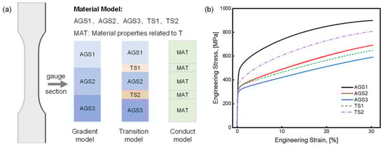
Figure 1.
Different models representing the gradient microstructure. (a) Schematic illustration of material parameter assignment where blue represents different gradient regions, orange represents the transitional regions, and green represents the regions with uniform material parameter and (b) the stress–strain relationship of Inconel 718 with different grain sizes.
In this study, a novel computational strategy is proposed to replace the conventional discrete assignment of gradient properties by introducing artificially controlled temperature fields into the finite element model. It is important to emphasize that the temperature values used in this context bear no physical significance; rather, they serve solely to generate a smoothly varying gradient field. By assigning constant temperatures to the regions with uniform microstructures and allowing thermal conduction to establish a steady-state distribution, a smooth temperature gradient is formed across the model. This temperature field is then used to define spatially varying material properties corresponding to the underlying gradient structure. After the properties are assigned, the artificial temperature field can be removed, enabling subsequent simulations under various thermal conditions (either isothermal or non-isothermal) to assess the deformation behavior of materials with gradient properties. As illustrated in the conduct model in Figure 1a, we construct an integrated temperature-dependent material framework for three grain-size regimes: AGS1 (20 μm), AGS2 (70 μm), and AGS3 (180 μm), numerically corresponding to placeholder temperatures 20 °C, 70 °C, and 180 °C, respectively. These temperatures are not operating temperatures and do not have any specific physical significance. The gradient region, corresponding to the transition zone in the conventional model, is initialized with boundary temperatures that match these values. Material parameters across this region are then automatically interpolated via thermal conduction, achieving a smooth and continuous transition in mechanical behavior.
To verify the computational accuracy of the conduct model, a macroscopic finite element simulation of uniaxial tension is performed. The stress distributions obtained from the three different modeling approaches are illustrated in Figure 2a–c. It can be observed that the conduct model exhibits negligible stress concentration at the gradient junction while maintaining an overall stress field comparable to the other methods. A stress quantification analysis is further conducted along the transition path A-A′, as shown in Figure 2d. The stress differences at the AGS1/AGS2 gradient junction are found to be 165 MPa, 80 MPa, and 0 MPa for the gradient model, the transition model, and the conduct model, respectively. Similarly, at the AGS2/AGS3 interface, the corresponding differences are 103 MPa, 50 MPa, and 0 MPa. Notably, in both the gradient and transition models, the peak stress at the AGS2/AGS3 junction equals or exceeds the maximum stress in the AGS3 region, which represents a primary source of computational inaccuracy. In contrast, the stress distribution along the A-A′ path in the conduct model remains smooth and continuously elevated without abrupt fluctuations, thereby significantly improving the accuracy of the simulation.
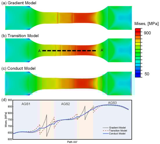
Figure 2.
Stress analysis of different models after uniaxial tensile. Stress distribution contour of (a) gradient model, (b) transition model, and (c) conduct model; (d) stress distribution along A-A′ path.
Complementarily, this approach improves the computational accuracy of the gradient model and eliminates stress concentrations at the gradient interface. The construction of the model does require an independent temperature conduction step prior to deformation and the predefinition of the temperature field in order to automatically capture the corresponding properties during the subsequent deformation. However, the additional computation primarily occurs during initialization (temperature field mapping <10% of total runtime), with minimal impact on the core deformation analysis. For components like metallic sealing rings, for which predictive accuracy outweighs computational savings, this trade-off proves operationally optimal.
4. Application of the Conduct Model to Compare the Service Performance of W-Shaped Sealing Rings with Gradient and Uniform Microstructures
Due to the distinctive cross-sectional geometry of metallic sealing rings, deformation within the W-shaped section exhibits a naturally occurring gradient distribution. To alleviate residual stresses induced by the forming process, heat treatment is typically performed prior to ring installation. In existing studies, it is generally assumed that mechanical property discrepancies arising from non-uniform deformation can be mitigated by subsequent heat treatment. Accordingly, a homogenization model is often adopted to assess the service performance of W-shaped metallic sealing rings. However, our previous investigations on Inconel 718 revealed that while heat treatment can partially relieve property differences induced by plastic strain, significant variations in yield strength, tensile strength, and elongation persist due to the retained gradient strain. To further investigate the influence of gradient mechanical properties on the overall service performance of the sealing ring, both homogenized and gradient models are developed in this section. For the gradient model, the temperature conduction method introduced in Section 3 is employed to assign spatially varying material properties. This approach effectively suppresses stress concentrations at the interfaces between different gradient regions, thereby enhancing the numerical accuracy of the simulation results.
The model presented in this section is employed to simulate the service performance of metallic sealing rings. A 3 mm segment of the sealing ring was selected as the representative region for analysis, as shown in Figure 3a,b. The model is meshed using C3D20RT elements, with an average element size of 0.08 mm (The verification of grid convergence can be found in Appendix A). Based on the residual strain distribution within the W-shaped cross-section of the formed sealing rings, five distinct plastic strain levels of Inconel 718—7%, 14%, 21%, 28%, 35% (denoted as PS07, PS14, PS21, PS28, PS35)—were selected within the range of 0~40%. The stress–strain responses of these five material states are illustrated in Figure 3c. In the homogenization model, a uniform material property is applied to the entire W section. This modeling framework consists of five distinct cases, each corresponding to a specific deformation state and labeled accordingly (PS07 to PS35).
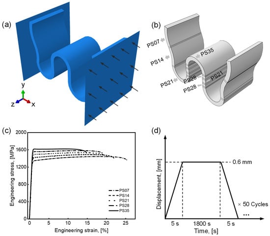
Figure 3.
Finite element model to predict the performance of sealing rings. (a) Boundary conditions, (b) conduct model with gradient deformation in which the PS07, PS14, PS21, PS28 and PS35 indicates the degree of plastic strain is 7%, 14%, 21%, 28% and 35%, (c) the corresponding material model, and (d) displacement-controlled loading profile.
In contrast, for the gradient model, the stress–strain relationships corresponding to different plastic strain levels are integrated into a unified material framework. These are mapped onto regions within the W-shaped cross-section according to the strain gradient, which is represented through an equivalent gradient temperature field, as shown in Figure 3b. During service simulation, the sealing ring is subjected to 0.6 mm cyclic compression applied by rigid indenters on both sides, following the displacement-controlled loading profile illustrated in Figure 3d. Two key performance indicators, i.e., the springback rate (φ) and equivalent plastic strain (p), both related to fatigue deformation, are quantitatively evaluated. The springback rate φ is defined as follows:
in which h is the initial height of the sealing ring, h0 is the height after compression, and h1 is the height after unloading.
The inset in Figure 4a presents the distribution of equivalent plastic strain and displacement in the sealing ring during cyclic service. The results indicate that displacement fluctuations caused by external vibrations during operation are transmitted through the contact interface between the sealing ring and the flange. Notably, plastic deformation is concentrated at the trough region of the sealing ring, where stress localization occurs. To further investigate this behavior, the evolution of plastic strain at the trough is extracted and is also shown in Figure 4a. The plastic strain exhibits rapid accumulation during the initial loading cycles, followed by a slower, quasi-linear growth phase. In this latter stage, the plastic strain increases linearly with the number of loading cycles. This progressive accumulation of plastic deformation leads to elastic attenuation, as demonstrated in Figure 4b. In the gradient model, the overall deformation trend remains consistent with that observed in the homogenization model. However, the deformation capacity, reflected by the rate and extent of plastic strain development, differs due to the presence of gradient mechanical properties.
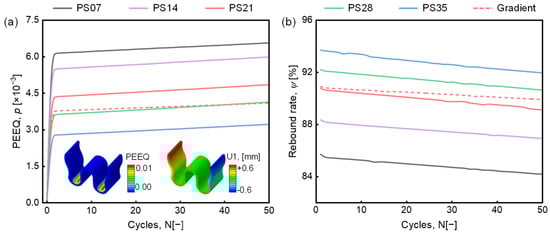
Figure 4.
(a) Equivalent plastic strain and (b) springback rate in different models.
Due to the elevated internal dislocation density and enhanced mechanical properties of materials subjected to significant pre-deformation, their resistance to further plastic deformation during service is substantially improved. As a result, the homogenization models, each corresponding to different degrees of prior deformation, show that plastic strain accumulation at the trough region decreases with increasing deformation magnitude. Conversely, the springback rate exhibits a rising trend. Among these models, PS21 demonstrates performance at the trough region comparable to that of the gradient model and is therefore selected as a benchmark for comparison. As illustrated by the red solid and dashed lines in Figure 4a,b, the gradient model exhibits reduced plastic strain accumulation relative to the PS21 model. This indicates that introducing a gradient structure effectively suppresses fatigue-induced plastic strain accumulation, thereby enhancing the fatigue life of the sealing ring. Additionally, the improved springback resistance observed in the gradient model suggests superior sealing performance.
To elucidate the relationship between fatigue and sealing performance over the service duration, a linear fitting analysis is performed on the evolution of plastic strain and springback rate. The corresponding results are summarized in Table 2, where a1 denotes the accumulation rate of plastic strain, b1 represents the initial plastic strain in the first loading cycle, a2 indicates the rate of elastic decay, and b2 corresponds to the springback rate immediately after the first unloading cycle. The results reveal that the degree of deformation introduced during the forming process plays a dominant role in determining the magnitude of initial plastic strain, while exerting only a limited effect on the subsequent accumulation rate or elastic decay rate. In contrast, the gradient model exhibits a noticeably lower plastic strain accumulation rate and reduced elastic attenuation, indicating a significant enhancement in both fatigue resistance and sealing performance. These findings underscore the importance of accurately accounting for the material gradient when predicting the long-term performance of metallic sealing rings. Proper incorporation of the gradient structure is thus critical to achieving reliable fatigue life predictions and ensuring optimal service reliability.
Table 2.
Fitting results of plastic strain and springback rate.
5. Design of Gradient Microstructure at the Trough Region of Metallic Sealing Rings
According to the results presented in Section 4, the presence of a gradient structure enhances resistance to plastic deformation, mitigates elastic attenuation, and consequently extends the service life of the component when compared to a uniform structure. To further improve the performance of gradient structures, this section focuses on the trough region, which endures the majority of plastic deformation. Given the challenges of implementing gradient structures in such localized regions within a macroscopic finite element model, a microscopic modeling approach is adopted. Crystal plasticity simulations are employed, incorporating the previously established criterion for dislocation-based stored-energy density, to investigate the influence of microstructure at the trough on the service performance of the sealing ring. Two types of crystal plasticity models are developed: one with a uniform grain size and the other with a gradient grain-size distribution. A grain-size range below 50 μm, determined based on the average grain size of the formed sealing ring, is selected to explore the relationship between grain size and the fatigue performance of the component [29,30]. Within the grain-size range of 0~50 μm, eight different grain-size combinations covering four gradient levels are then used to evaluate the effects of grain-size gradients on sealing-ring performance.
The crystal plasticity models employed in this study are quasi-three-dimensional, with dimensions of 50 μm × 50 μm × 3 μm, as illustrated in Figure 5a. As shown in Figure 5b, five uniform grain-size models with grain sizes of 10 μm, 20 μm, 30 μm, 40 μm, and 50 μm are constructed. For the gradient grain-size model, three regions with distinct grain sizes are assigned from left to right, while the overall crystal orientations are randomly distributed. The loading profile applied, depicted in Figure 5c, is extracted from the trough region of the gradient model discussed in Section 5 and used to define the boundary conditions, as shown in Figure 5a. The material properties of Inconel 718 established in our previous work [1] are used in this study, as shown in Table 3. The failure criterion based on dislocation stored-energy density, as proposed in ref. [1], is adopted here to quantify the mechanical property variations induced by grain size. This approach enables a physically grounded assessment of grain-size effects on deformation behavior and fatigue life.
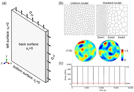
Figure 5.
The crystal plasticity model with different grain sizes and gradients. (a) Boundary conditions, (b) geometry and pole figure, and (c) loading profile.
Table 3.
Material parameters for Inconel 718 [1].
The prediction of fatigue life using critical stored-energy density is conducted under the conditions of random texture as well as specific gradient region dimensions. A definite fatigue life value is derived from the results of the study. It is worth noting that the location and the evolution tendency of stored-energy density changes slightly when the grain orientation varies, and thus the predicted fatigue life value fluctuates. However, the effect of this fluctuation is negligible on the fatigue life window compared to the effect of the overall gradient or the change in grain size.
Figure 6a illustrates the evolution of stored-energy density at the point of maximum concentration for each uniform grain-size model. As commonly observed in fatigue deformation, the stored-energy density initially increases rapidly and then enters a steady accumulation phase. The durations of this steady accumulation stage for AVG10 through AVG50 are 6, 9, 16, 18, and 20 cycles, respectively. This trend reflects the influence of grain size on plastic deformation behavior. Smaller grain sizes, with more grain boundaries, restrict dislocation motion and delay the onset of slip, leading to earlier stabilization of stored-energy accumulation. In contrast, larger grains accommodate more extensive plastic deformation, which promotes the generation of geometrically necessary dislocations (GNDs) to maintain strain compatibility, thereby resulting in higher stored-energy density.
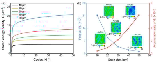
Figure 6.
Simulation results of uniform grain-size model. (a) Evolution of stored-energy density G and (b) accumulation of stored-energy density and fatigue life.
The steady-state accumulation rates of stored-energy density are extracted and presented in Figure 6b. The accumulation rate increases nearly linearly with grain size, with a notably sharper rise observed when the grain size exceeds 20 μm. The fatigue life of the sealing ring is then estimated based on a previously identified critical stored-energy density threshold of 89 J m−2, indicated by the blue dotted line in Figure 6b. Components with larger grain sizes exhibit significantly reduced fatigue life; for example, at a grain size of 50 μm, the predicted fatigue life drops to approximately 1100 cycles. These results underscore the importance of designing a gradient grain structure within the 0~50 μm range to ensure the reliable performance of metallic sealing rings. Properly controlling the gradient can effectively mitigate localized energy accumulation and extend service life under cyclic loading.
Subsequently, the study is extended to more complex scenarios by examining how gradient microstructures affect the accumulation of dislocation stored-energy density. Four gradient magnitudes, i.e., 5 μm, 10 μm, 15 μm, and 20 μm, were selected, and eight gradient models were established based on the grain-size configurations listed in Table 4. The mechanical response of each model was quantitatively characterized using the evolution of dislocation stored-energy density, as shown in Figure 7a.
Table 4.
Matching relationship of grain size in gradient model.
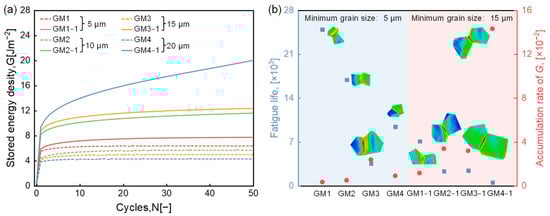
Figure 7.
Simulation results of gradient grain-size model. (a) Evolution of stored-energy density G and (b) accumulation of stored-energy density and fatigue life.
It is observed that the accumulation of stored-energy density is primarily governed by the minimum grain size in the gradient microstructure. When the minimum grain size is sufficiently small (e.g., 5 μm), the overall stored-energy density remains relatively low. A comparison among different models further reveals that, for a minimum grain size of 5 μm, the stored-energy accumulation decreases with increasing gradient magnitude, i.e., opposite to the trend observed when the minimum grain size is 15 μm. This suggests that a pronounced grain-size gradient can better accommodate deformation incompatibility, especially when fine grains dominate the microstructure.
Figure 7b presents the accumulation rates of stored-energy density and the corresponding fatigue life across the different gradient models. The inset in Figure 7b shows that the regions of highest energy concentration are randomly distributed in the gradient microstructure. The accumulation rate is largely influenced by the maximum grain size, while smaller grains play a synergistic role in moderating the overall accumulation, as exemplified by the comparisons between GM2 and GM1-1, as well as between GM3 and GM2-1. A positive correlation is found between the energy accumulation rate and both the gradient magnitude and maximum grain size.
Moreover, the fatigue life of the sealing component tends to decline with increasing gradient magnitude. Therefore, when designing gradient microstructures, it is crucial to strike a balance: minimizing stored-energy density through deformation coordination enabled by fine grains, while avoiding excessive accumulation caused by oversized grains. Such a comprehensive design strategy is essential for optimizing the fatigue performance and sealing reliability of the component.
6. Conclusions
A new method to enhance the simulation accuracy of macroscopic finite element models for gradient structures is proposed in this study. This method is applied to evaluate the service performance of sealing rings with both uniform and gradient strain distributions. Furthermore, the correlation between grain size at the trough region and service performance is investigated using a crystal plasticity model. Based on these analyses, the mechanical behavior of gradient microstructures is systematically assessed. The main conclusions are summarized as follows:
- (1)
- The proposed modeling approach replaces the conventional gradient-type property assignment with an artificial temperature field, which has no physical significance but is used to induce smooth material transitions. A thermal conduction zone is introduced between different regions to establish a continuous material property distribution. This approach effectively reduces stress concentrations to near-zero levels and significantly improves simulation accuracy.
- (2)
- Neglecting gradient deformation in simulations can lead to inaccurate estimations of the service life of sealing rings. When the strain level at the trough is specified, the presence of a strain gradient enhances the resistance to plastic deformation and alleviates elastic degradation during cyclic loading.
- (3)
- When the mechanical behavior of gradient microstructures is characterized via dislocation stored-energy density, the minimum grain size determines the energy density level, and the maximum grain size governs the accumulation rate under the same service conditions. Therefore, both factors must be jointly considered in the microstructural design of gradient materials to optimize performance.
7. Outlook
Building on this work, the proposed simulation framework quantifies macroscopic plastic strain accumulation, evaluates springback behavior, and predicts fatigue life across microstructural variants. However, the influence of multi-pass roll forming parameters on gradient strain characteristics (distribution and magnitude) in the W-section is beyond the scope of this study. Operational factors, including temperature, gas pressure, and preload, remain unexamined in the gradient microstructure performance assessment. The consideration of forming and service factors is essential for high-performance fabrication of sealing rings. In future research, on the one hand, the correlations between forming parameters and gradient strain distribution can be further explored while ensuring forming stability. The reverse optimization of forming processes will be realized based on plastic deformation and springback behavior across macro-gradient configurations. On the other hand, fatigue response in varied service environments and its governing factors can be established to enable service condition-specific microstructural design of sealing rings. Advancing this research may improve the sealing-ring springback rate, reduce leakage, and increase the service life of the sealing ring even further.
Author Contributions
Conceptualization, P.Z. and Z.Z.; methodology, P.Z. and Z.Z.; software, Z.Z. and L.T.; formal analysis and data curation, P.Z. and H.Z.; investigation, P.Z., Z.S. and S.R.; resources, G.Y.; writing—original draft preparation, P.Z.; writing—review and editing, Z.Z. and H.Z.; visualization, L.T., Z.S. and S.R.; supervision, Z.Z.; funding acquisition, Z.Z., L.T., H.Z. and P.Z. All authors have read and agreed to the published version of the manuscript.
Funding
This research was funded by the Shenzhen Science and Technology Program, grant number: GJHZ20240218114404010; the State Key Laboratory of High-end Heavy-load Robots, grant number: HHR2024010106; the Key Research and Development Program of Shaanxi Province, grant number: 2025CY-YBXM-086; and the Innovation Foundation for Doctor Dissertation of Northwestern Polytechnical University, grant number: CX2023046.
Data Availability Statement
The original contributions presented in this study are included in the article. Further inquiries can be directed to the corresponding authors.
Conflicts of Interest
Author Liheng Tuo was employed by the company Midea Group Co., Ltd., Authors Zhiyan Sun and Shuai Ren were employed by the company HBIS Group Co., Ltd., and Author Gaihuan Yuan was employed by the company State Nuclear Baoti Zirconium Industry Co., Ltd. The remaining authors declare that the research was conducted in the absence of any commercial or financial relationships that could be construed as a potential conflict of interest.
Appendix A. Mesh Convergence Verification of Finite Element Model for Sealing-Ring Service Performance Prediction
Another four models with different mesh sizes (0.02 mm, 0.05 mm, 0.11 mm, 0.14 mm) were constructed to analyze the mechanical response of the sealing ring. The fitted plastic strain accumulation and springback rate calculated from different grid sizes are shown in Figure A1. The results show that the calculation results are relatively stable when the mesh size is less than 1/3 of the thickness of the sealing ring (0.3 mm), and conversely, the deviation increases. Therefore, in order to ensure the calculation efficiency and accuracy, a 0.08 mm mesh size is chosen for the service performance analysis of the sealing ring, and its size is independent of plastic strain and rebound rate.
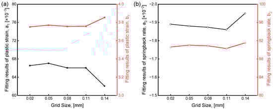
Figure A1.
Fitting results of plastic strain and springback rate under different grid sizes. (a) a1 and b1 of plastic strain and (b) a2 and b2 of springback rate.
References
- Zheng, Z.; Zhao, P.; Zhan, M.; Li, H.; Lei, Y.; Fu, M.W. Understanding of the Fatigue Crack Nucleation in Metallic Sealing Rings by Explicitly Incorporating the Deformation History from Manufacturing to Service. Int. J. Fatigue 2022, 164, 107174. [Google Scholar] [CrossRef]
- Porter, C.; Zaman, B.; Pazur, R. A Critical Examination of the Shelf Life of Nitrile Rubber O-Rings Used in Aerospace Sealing Applications. Polym. Degrad. Stab. 2022, 206, 110199. [Google Scholar] [CrossRef]
- Wang, Y.; Luo, W.; Liu, S.; Feng, H.; Li, J.; Wang, J. A Model for Reliability Assessment of Sealing Performance of the C-Shaped Metal Sealing Ring at the Outlet of the Subsea Tubing Hanger. Ocean Eng. 2022, 243, 110311. [Google Scholar] [CrossRef]
- Jia, X.; Chen, H.; Li, X.; Wang, Y.; Wang, L. A Study on the Sealing Performance of Metallic C-Rings in Reactor Pressure Vessel. Nucl. Eng. Des. 2014, 278, 64–70. [Google Scholar] [CrossRef]
- Shen, M.; Peng, X.; Xie, L.; Meng, X.; Li, X. Deformation Characteristics and Sealing Performance of Metallic O-Rings for a Reactor Pressure Vessel. Nucl. Eng. Technol. 2016, 48, 533–544. [Google Scholar] [CrossRef]
- Jiang, Y.; Suo, S.; Wei, Y.; Wang, K.; Wang, Y. Research on Working State Stress and Compression Recovery Performance of Metallic W-Sealing Ring. Lubr. Eng. 2018, 43, 31–36. [Google Scholar]
- Chen, J.; Wang, Y.; Li, Q.; Li, N. Analysis of Influence Factors on Sealing Effect of W-Shaped Metal Seal Ring in Aero Engine. Adv. Aeronaut. Sci. Eng. 2018, 9, 617–622. [Google Scholar]
- Li, W.; Jia, Z.; Yin, W.; Cheng, J.; Ran, J. Fatigue Life Prediction of Multilayer Structure Metallic W-Ring Based on Thermal-Mechanical Coupling. Hunan Daxue Xuebao/J. Hunan Univ. Nat. Sci. 2019, 46, 41–47. [Google Scholar] [CrossRef]
- Shao, G.; Li, H.; Zhang, X.; Zhan, M.; Li, Z.; Liu, Q. External-Internal Composite Spinning Technology for Forming Thin-Walled Ω-Sectioned Ring of Superalloy. J. Mater. Process. Technol. 2021, 291, 117004. [Google Scholar] [CrossRef]
- Ding, X.Y. The Structure Optimization Design for the W-Type Metallic Sealing Ring Based on the MOGA Algorithm. Appl. Mech. Mater. 2015, 727–728, 541–545. [Google Scholar] [CrossRef]
- Jiang, Y.; Suo, S. Comprehensive Performance Optimal Design of Metallic W-Ring under Working Conditions. Lubr. Eng. 2019, 44, 76–80. [Google Scholar] [CrossRef]
- Li, W.; Wang, L.; Jia, Z.; Shan, X. Structure Optimization Design of Metallic W-ring Used in Aviation Engine. Lubr. Eng. 2019, 44, 12–16. [Google Scholar] [CrossRef]
- Bo, H.; Cao, H.; Li, Y.; Yang, L. Failure Analysis and Optimized Verification of Metal W-Sealing Ring of Aero-Engine at High Temperature. Lubr. Eng. 2018, 43, 127–131. [Google Scholar] [CrossRef]
- Skamniotis, C.; Grilli, N.; Cocks, A.C.F. Crystal Plasticity Analysis of Fatigue-Creep Behavior at Cooling Holes in Single Crystal Nickel Based Gas Turbine Blade Components. Int. J. Plast. 2023, 166, 103589. [Google Scholar] [CrossRef]
- Zheng, Z.; Zhan, M.; Fu, M.W. Microstructural and Geometrical Size Effects on the Fatigue of Metallic Materials. Int. J. Mech. Sci. 2022, 218, 107058. [Google Scholar] [CrossRef]
- Shen, S.; Zhan, M.; Gao, P.; Hao, W.; Dunne, F.P.E.; Zheng, Z. Microstructural Effects on Thermal-Mechanical Alleviation of Cold Dwell Fatigue in Titanium Alloys. Crystals 2022, 12, 208. [Google Scholar] [CrossRef]
- Yan, B.; Meng, B.; Zhu, Y.; Wang, Y.; Wan, M. A Global Springback Compensation Method for Manufacturing Metallic Seal Ring with Complex Cross-Section and Submillimeter Precision. J. Mater. Process. Technol. 2024, 331, 118498. [Google Scholar] [CrossRef]
- Shao, G.; Li, H.; Zhang, X.; Zou, J.; Huang, Z.; Zhan, M. Modelling of Ultrasonic Vibration-Assisted Forming Considering the Distribution of Ultrasonic Field with Structure Deformation. Int. J. Plast. 2023, 170, 103744. [Google Scholar] [CrossRef]
- Chen, K.; Luo, J. Preparing Gradient Microstructure to Achieve Enhanced Performance in GH4586 Superalloy: Experiments and Models. Mater. Sci. Eng. A 2024, 915, 147231. [Google Scholar] [CrossRef]
- Yang, L.; Chen, Z.; Ma, X.; Zhong, D.; Zhao, X.; Xiao, L.; Fang, X. Improvement of Strength and Ductility in a Gradient Structured Ni Fabricated by Severe Torsion Deformation. Mater. Sci. Eng. A 2021, 826, 141980. [Google Scholar] [CrossRef]
- Jiang, W.; Xu, P.; Li, Y.; Wang, H.; Cai, Z.; Li, J.; Liang, Y.; Liang, Y. Effect of a Gradient Structure on the Mechanical Performance of Inconel 718 Ni-Based Superalloy at Elevated Temperatures. J. Mater. Res. Technol. 2023, 23, 2031–2042. [Google Scholar] [CrossRef]
- Jian, S.; Wang, J.; Xu, D.; Ma, R.; Huang, C.; Lei, M.; Liu, D.; Wan, M. Gradient Microstructure and Mechanical Properties of Ti-6Al-4V Titanium Alloy Fabricated by High-Frequency Induction Quenching Treatment. Mater. Des. 2022, 222, 111031. [Google Scholar] [CrossRef]
- Qiang, W.; Wu, Q.; Long, L. Gradient Structured Al Alloy with a Synergistic Improvement of Strength-Ductility Obtained by Friction Stir Processing. Mater. Sci. Eng. A 2024, 916, 147376. [Google Scholar] [CrossRef]
- Shi, Y.; Shang, W.; Zhang, X.; Liang, S.; Li, S.; Chen, W.; Liu, H.; Xu, D.; Liu, X.; Lv, G.; et al. Superior Mechanical Properties and Strengthening–Toughening Mechanisms of Gradient-Structured Materials. Mater. Sci. Eng. A 2022, 861, 144365. [Google Scholar] [CrossRef]
- Zheng, Z.; Balint, D.S.; Dunne, F.P.E. Discrete Dislocation and Crystal Plasticity Analyses of Load Shedding in Polycrystalline Titanium Alloys. Int. J. Plast. 2016, 87, 15–31. [Google Scholar] [CrossRef]
- Zheng, Z.; Zhao, P.; Zhan, M.; Shen, S.; Wang, Y.; Fu, M.W. The Roles of Rise and Fall Time in Load Shedding and Strain Partitioning under the Dwell Fatigue of Titanium Alloys with Different Microstructures. Int. J. Plast. 2022, 149, 103161. [Google Scholar] [CrossRef]
- Dunne, F.P.E.; Rugg, D.; Walker, A. Lengthscale-Dependent, Elastically Anisotropic, Physically-Based Hcp Crystal Plasticity: Application to Cold-Dwell Fatigue in Ti Alloys. Int. J. Plast. 2007, 23, 1061–1083. [Google Scholar] [CrossRef]
- Gibbs, G.B. Thermodynamic Analysis of Dislocation Glide Controlled by Dispersed Local Obstacles. Mater. Sci. Eng. 1969, 4, 313–328. [Google Scholar] [CrossRef]
- Zhang, X.; Li, H.; Xiang, Z.; Li, Z.; Zhan, M. Targeted Control of Microstructure Homogeneity of Ni-Based Superalloy Complex Component by Electric Pulse. Mater. Lett. 2022, 321, 132429. [Google Scholar] [CrossRef]
- Li, H.; Xiang, Z.; Zhang, X.; Liu, X.; Gao, J.; Shao, G. Mechanism and Rules of Microstructure Homogenization in Non-Uniform deformed GH4738 under Pulsed Current. J. Plast. Eng. 2023, 30, 102–110. [Google Scholar] [CrossRef]
Disclaimer/Publisher’s Note: The statements, opinions and data contained in all publications are solely those of the individual author(s) and contributor(s) and not of MDPI and/or the editor(s). MDPI and/or the editor(s) disclaim responsibility for any injury to people or property resulting from any ideas, methods, instructions or products referred to in the content. |
© 2025 by the authors. Licensee MDPI, Basel, Switzerland. This article is an open access article distributed under the terms and conditions of the Creative Commons Attribution (CC BY) license (https://creativecommons.org/licenses/by/4.0/).