Article

Relationship Between Structure and Functional Properties of Ultrafine-Grained Fe-Mn-Si Alloys for Temporary Implants

1
A.A. Baikov Institute of Metallurgy and Materials Science of the Russian Academy of Sciences, 119334 Moscow, Russia
2
N.N. Blokhin National Medical Research Center of Oncology (N.N. Blokhin NMRCO), Ministry of Health of the Russian Federation, 115478 Moscow, Russia
3
Research and Education Center for Biomedical Engineering, National University of Science and Technology “MISIS”, Leninsky Prospect, 4, 119049 Moscow, Russia
4
P.N. Lebedev Physical Institute of the Russian Academy of Sciences, 119991 Moscow, Russia
5
Department of Physical Materials Science, National University of Science and Technology “MISIS”, Leninsky Prospect, 4, 119049 Moscow, Russia
6
A.M. Prokhorov General Physics Institute of RAS, Vavilov Str., 38, 119991 Moscow, Russia
7
Laboratory of Hybrid Nanostructured Materials, National University of Science and Technology “MISIS”, Leninsky Prospect, 4, 119049 Moscow, Russia
8
Laboratory of Mechanical Properties of Nanostructured Materials and Superalloys, Belgorod State University, 308015 Belgorod, Russia
9
Herbert Gleiter International Institute, Liaoning Academy of Materials, Shenyang 110016, China
*
Author to whom correspondence should be addressed.
Crystals 2025, 15(5), 424; https://doi.org/10.3390/cryst15050424
Submission received: 31 March 2025 / Revised: 26 April 2025 / Accepted: 29 April 2025 / Published: 30 April 2025
(This article belongs to the Special Issue Crystal Plasticity (4th Edition))

Abstract

:
This paper presents a study of microstructure formation in bioresorbable Fe-Mn-Si alloys for temporary implants under high-pressure torsion (HPT) at room temperature and at 300 °C. The effect of silicon on the mechanism of microstructure formation under HPT and, as a consequence, on the mechanical, corrosion and biological properties of the alloys is studied. It is established that Si promotes martensitic transformation. HPT leads to an increase in the microhardness values of the studied alloys from ~1560 MPa in the initial state to ~5500 MPa (160–560 HV) due to structure refinement and phase transformation. An increase in the electrochemical corrosion rate of Fe-Mn-Si alloys to ~0.5 mm/year is established due to grain refinement to nanosize and the formation of strain-induced martensite. In vitro cytotoxicity and induced hemolysis studies showed that Fe-Mn, Fe-Mn-3.7Si, and Fe-Mn-5Si alloys after annealing and HPT can be characterized as biocompatible.

1. Introduction

Despite ongoing research to improve the corrosion and functional properties of biomaterials for permanent implants made of stainless steel [1,2,3,4,5,6,7], titanium [1,8,9,10,11,12,13,14] and cobalt [1,15,16,17] alloys, there is increased interest in corrodible metallic biomaterials for use in a number of medical devices [18,19,20]. These include biodegradable alloys based on Mg [21,22,23,24,25,26], Zn [27,28,29], and Fe [30,31,32,33]. Compared with Mg- and Zn-based alloys, iron-based alloys are stronger and have mechanical properties similar to stainless steel. Therefore, bioresorbable Fe-based alloys have long been considered promising materials for the temporary medical implants, such as fixators for osteosynthesis [18,19,20] or cardiovascular stents [30,31,32,33]. Among iron-based materials, Fe-Mn alloys are the most suitable for the development of bioresorbable medical devices, since Mn significantly reduces the corrosion potential of Fe-based alloys [20,31,34,35]. It is believed that these alloys have promising potential for such applications [36,37,38]. At the same time, their main disadvantage is a fairly slow biodegradation process, which does not meet the requirements for materials for temporary implants [34]. A slow rate of biodegradation can lead to the occurrence of side effects associated with chronic inflammation due to the release of cytotoxic ions during long-term use, which is usually observed when using permanent implants and leads to repeated surgical operations to remove or replace the implant. In solving the problem of slow corrosion rate, a combination of alloying [36,37,39,40,41,42,43], processing [44,45,46,47,48,49], and the production method [50,51,52] can become a universal approach for obtaining mechanical, corrosion, and ferromagnetic properties of Fe-Mn alloys that meet the requirements imposed on their subsequent specific application.
At the same time, the mechanical behavior of Fe-Mn alloys is initially determined by the low stacking fault energy (SFE), since SFE is a key factor controlling the structure formation mechanism [53]. It is known that the SFE value is primarily determined by the crystallographic nature of the material but is influenced by the chemical composition [54]. A decrease in SFE shifts the structure formation at deformation of high-manganese alloys from dislocation slip and twinning to martensitic transformation [53]. Silicon is one of the elements whose addition to the Fe-Mn base reduces the SFE and promotes the strain -induced γ (fcc) → ε (hcp) martensitic transformation [55]. It is exactly this martensitic transformation followed by the reverse transformation upon heating that leads to the appearance of the shape memory effect (SMA) in these alloys [56,57,58].
At present, many studies are dedicated to Fe-Mn-Si alloys [47,48,59,60,61]. Implantable devices made from Fe-Mn-Si alloys in their antiferromagnetic phase (austenite or ε-martensite) remain compatible with magnetic resonance imaging (MRI), enabling effective medical imaging during patient monitoring. For the first time, the Fe-30Mn-6Si alloy with SMA was characterized as biocompatible based on the results of in vitro experiments and proposed as a medical bioresorbable alloy in [59]. Subsequently, an in vivo study on rats confirmed its biocompatibility and suitability for use in osteosynthesis [60]. However, until now, a state of the Fe-Mn-Si alloy has not been developed, the biodegradation rate of which corresponds to the osteosynthesis rate. Another disadvantage inherent to iron-based alloys is the high elastic modulus (~120 GPa), which significantly exceeds the Young’s modulus of cortical bone (~20 GPa), which adversely affects the biomechanical compatibility of the implant and bone [62]. Research aimed at obtaining a lower elastic modulus [47,63,64], as well as the development of alloys with a higher degradation rate would make it possible to create an orthopedic bioresorbable metalware.
It should be noted that structural defects with increased free energy often serve as corrosion initiation points [65]. In addition, nonequilibrium intermetallic phases, usually formed at dislocation sites and grain boundaries [66], are the cause of galvanic corrosion. Moreover, it is known that grain size affects corrosion behavior, and its refinement increases the density of grain boundaries. The type of boundaries in turn affects corrosion resistance in different ways [67,68]. It is known that severe plastic deformation (SPD) results in the production of a highly defective structure with a high density of boundaries of structural elements. Therefore, it can become an effective tool for increasing the degradation rate. The implementation of this approach was demonstrated in Fe-Mn alloys through equal-channel angular pressing (ECAP), as documented in prior research [45,46]. It is important to note that the obtained strength characteristics of these alloys after ECAP are high enough to ensure veritable miniaturization of implantable devices [45,46,48]. It is worth noting that the degradation rate of the Fe-Mn-5Si alloy after ECAP, despite alloying, was slightly higher than that of commercially pure iron [48]. This effect was explained in [48] by the formation of low-energy strain-induced twins of high density in the austenitic structure as a result of ECAP at 400 °C, which increase corrosion resistance, in contrast to twins in magnesium alloys, where on the contrary, its decrease is observed [69].
The aim of this work was to create various structural-phase states of the studied Fe-Mn alloys in the process of high-pressure torsion (HPT) and determine their effect on mechanical and functional characteristics, including the degradation rate, as well as biocompatibility. To create various structural states, the possibility of using various mechanisms of structure formation during deformation was used, from the formation of strain-induced martensite to twinning and dislocation slip, by changing the temperature under conditions of very high strain degrees. Since silicon affects the mechanism of structure formation by reducing the stacking fault energy, alloys with different silicon contents were selected for this study. One of the compositions Fe-29% Mn-5% Si (wt.%) is close to the composition with a pronounced shape memory effect, the improvement of the functional characteristics of which is the focus of the efforts of many scientists.

2. Materials and Methods

2.1. Preparation and Processing of Alloys

Alloys of the compositions Fe-27 wt.% Mn, Fe-29 wt.% Mn-3.7 wt.% Si and Fe-29 wt.% Mn-5.2 wt.% Si with minor impurities (<0.01 wt.% C, <0.005 wt.% P, <0.003 wt.% S) were melted in a vacuum-arc melting Leybold Gereus L200DI furnace (Leybold, Cologne, Germany) from commercially pure iron, electrolytic manganese (~99.8% Mn) and silicon. The obtained ingots (~1000 g) were forged at a temperature of 1100 °C in order to obtain rods with a diameter of up to 20 mm. The initial state was taken after homogenization annealing at a temperature of 1100 °C for 12 h in a vacuum in quartz tubes with subsequent cooling in water. Deformation by torsion under pressure (P = 6 GPa) was carried out in a Bridgman anvil-type installation on samples 1.5 mm thick with a diameter of 10 mm for alloys with Si and on samples with a diameter of 20 mm for the Fe-Mn alloy. Two isothermal deformation modes were used at a temperature of 300 °C and at room temperature in order to obtain strain-induced ε-martensite. In all modes, deformation was carried out up to 10 revolutions, which corresponded to the equivalent plastic strain at the middle of the radius of the samples of ~5 for alloys with Si and ~5.7 for the Fe-Mn alloy.

2.2. Microstructural Characterization and Phase Analysis

The initial micro structure of the alloys was studied using a JSM-7001F scanning electron microscope (JEOL, Tokyo, Japan). The average grain size was calculated using the random secant method with Image ExpertPro 3 software (Image Expert, Moscow, Russia). The structure of the alloys after deformation was studied by transmission electron microscopy (TEM) using a JEM 2100 electron microscope (JEOL, Tokyo, Japan). Taking into account the heterogeneity of the samples after HPT, the position for studying the structure were clearly defined and coincided for all the studied state. Thin foils for TEM were cut from a place at the middle of the radius of the HPT samples. and prepared by grinding to 90 μm with subsequent thinning up to perforation on a TenuPol-5 setup (Struers, Copenhagen, Denmark). The phase composition of the studied alloys was determined using a Rigaku Ultima IV diffractometer (Rigaku, Tokyo, Japan) with CoKα radiation (wavelength: λ = 1.7902 Å). To analyze the diffraction patterns, the Rietveld method implemented in the PDXL2 software package (Rigaku, Tokyo, Japan) and the PDF-2 powder diffraction pattern database (ICDD) were used. Instrumental broadening was accounted for using the LaB6 standard, which exhibits no physical broadening.

2.3. Microhardness Measurements

Microhardness measurements were performed using the Wolpert Wilson® microhardness tester 402 MVD (Instron, Norwood, MA, USA) for measuring Vickers hardness under a load of 0.1 kgf with a hold time of 15 s. Microhardness of the samples was measured along the surface of the HPT disks by constructing squares inscribed in a circle with sides of 7 and 14 mm for HPT-treated disks with a diameter of 10 and 20 mm, respectively. Measurements were performed according to coordinates specified in the form of a matrix in automatic mode with a measurement step of 0.5 mm and 1 mm for disks with a diameter of 10 and 20 mm, respectively. Additionally, microhardness was measured along two mutually perpendicular diagonals with the measurement step described above.

2.4. Potentiodynamic Polarization (PDP) Measurements

Electrochemical characterization of Fe-Mn alloy corrosion resistance was performed through the potentiodynamic polarization (PDP) method. The experiments were carried out using an SP-300 (Bio-Logic SAS, Seyssinet-Pariset, France) potentiostat via a three-electrode electrochemical PAR cell (Ametek Instruments, Oak Ridge, TN, USA). During the measurement, the alloy sample serves as the working electrode, the platinum mesh serves as the counter electrode, and the Ag/AgCl electrode serves as the reference electrode. Corrosion studies were carried out in a physiological solution of 0.9% NaCl (pH = 7.4) at room temperature. The studied sample was ground and polished to a mirror surface. To limit the contribution of surface roughness to the uncertainty of the result, we measured the roughness parameter using an optical profilometer S neox (Sensofar, Terrassa, Spain). The arithmetic mean deviation of the profile of the studied samples after HPT was approximately 5 nm for all samples. PDP scans were performed at a rate of 1 mV/s, spanning from −1000 V to EOC + 300 mV, where EOC is the open-circuit potential. A 20 min stabilization period ensured consistent PDP measurements. The obtained almost identical curves confirm a stable potential of the surface. Six consecutive scans were carried out for each alloy structural condition. Corrosion parameters—including corrosion potential, current density, and corrosion rate—were derived using software (BioLogic, Seyssinet-Pariset, France) according to the established protocols [70].

2.5. Mass Loss Test

To validate the electrochemical findings, mass loss immersion tests in DMEM (Dul-becco’s Modified Eagle Medium) were conducted following guidelines for laboratory corrosion testing [71]. Quarter-disk-shaped samples (10 mm diameter, 1 mm thickness) with mirror-polished surfaces were prepared in triplicate for each alloy condition (annealed and HPT-processed). The samples were sterilized in 70% ethanol for 2 h, dried and incubated in 1 mL of DMEM-based growth medium supplemented with 10% fetal bovine serum with 4 mM glutamine, and 100 unit/mL penicillin/streptomycin (all components-PanEco, Russia) at 37 °C in a humidified 5% CO2 atmosphere. After one day and after fourteen-day samples were extracted, rinsed with distilled water, dried, and weighed to quantify mass loss.

2.6. Biocompatibility In Vitro Measurements

Before studying the biocompatibility, the samples after HPT and in the initial state were immersed in 70% ethanol for 2 h, followed by drying in a sterile atmosphere. In each study, the properties of at least three alloy samples were studied after each treatment. To assess the biocompatibility, alloy samples in the form of a ¼ disk with a diameter of 10 mm and a thickness of 1.5–2 mm were used. The hemolysis and cytotoxicity induced by them in vitro were assessed as described in the previous study [22]. The duration of incubation of samples with CBA mouse blood cells in a complete growth medium for assessing the induction of hemolysis corresponded to two and four hours, and for 1 day for assessing cytotoxicity. In the control, the cells were incubated under similar conditions in the absence of samples. The results of the cellular response assessment were presented in the Mean ± Standard deviation format. Then, a comparative statistical analysis was carried out, assessing the reliability of differences in the indices of cellular destruction under the influence of the studied alloys in comparison with the control. Differences were considered significant at p < 0.05. Hemolysis and cytotoxicity of Fe-Mn alloys after annealing and HPT calculated as percentage relative to control for comparing the biological activity of different alloy samples with each other.
All manipulations with laboratory animals were preliminarily approved by the decision of the local ethics committee N.N. Blokhin NMRCO (#5-2024 dated 27 November 2024).

3. Results

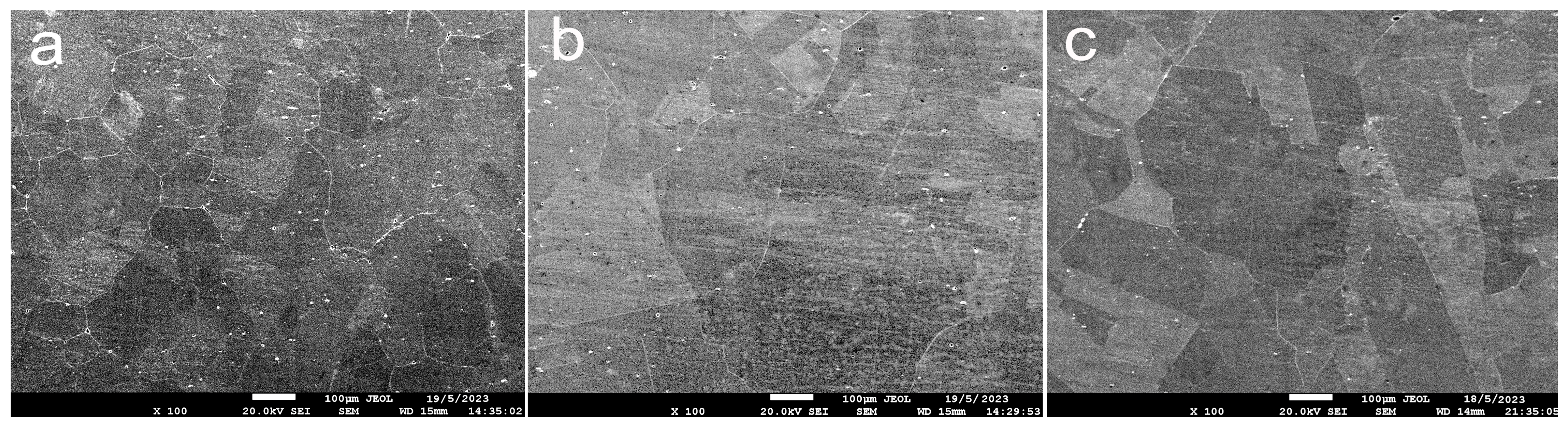
3.1. Metallographic Features of the Fe-Mn Alloys After Annealing

The initial microstructure of the alloys was a coarse-grained structure with an aver-age grain size of 189 ± 17 μm for the Fe-Mn alloy, 221 ± 21 μm with annealing twins of 24 ± 8 μm thickness for the Fe-Mn-3.7Si alloy and 160 ± 12 μm with annealing twins of 37 ± 5 μm thickness in the Fe-Mn-5Si alloy (Figure 1).

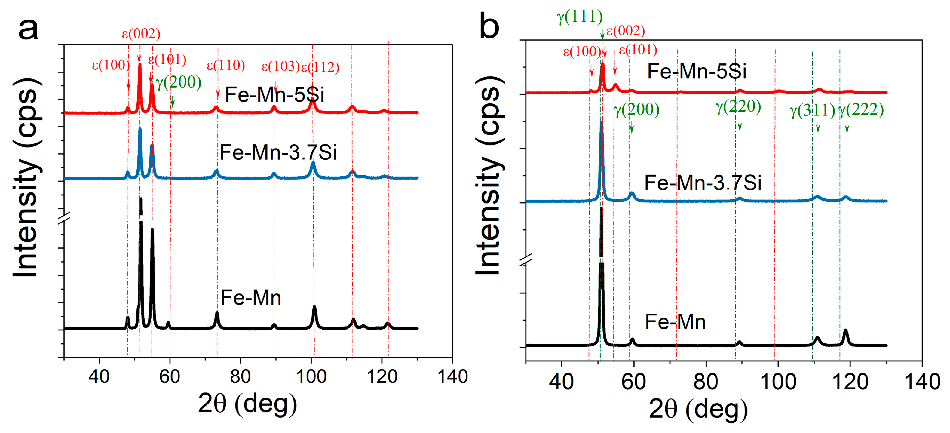
3.2. X-Ray Diffractions of the Fe-Mn Alloys After HPT

Quantitative X-ray diffraction analysis revealed the presence of a complete martensitic γ → ε transformation in Si alloys deformed at room temperature. In the case of HPT at room temperature, a partial martensitic transformation was observed in the Si-free alloy with the presence of 94.5% ε-martensite and 5.5% austenite (Figure 2, Table 1). In the case of HPT at a temperature of 300 °C, a partial martensitic transformation occurs only in the alloy with a maximum Si content of 5% (81.5% ε-martensite and 18.5% austenite). Two other alloys, Fe-Mn and Fe-Mn-3.7Si, obtained by HPT at a temperature of 300 °C had a fully austenitic structure (Figure 2).
The parameters of the fine crystal structure of the alloys, namely, the crystallite sizes and the microstrain values (Table 1), were determined using the X-ray line analysis. The dislocation density was calculated by recalculating the microstrains obtained by the com-plete fitting of the diffraction profile using the Rietveld method. The line profiles were ap-proximated by a Gaussian function. It was found that the values of microstrains increased with increasing HPT temperature. The crystallite sizes for the austenitic Fe-Mn alloy after HPT at 300 °C and for the Fe-Mn-3.7Si and Fe-Mn-5Si alloys after HPT at room temperature indicate the formation of a nanostructural state in the alloys with an average crystal-lite sizes of 73.7 ± 12.5 nm, 94.3 ± 16 nm, and 104.6 ± 19.2 nm, respectively. In the two-phase Fe-Mn alloy after HPT at room temperature and the Fe-Mn-5Si alloy after HPT at a temperature of 300 °C with the occurrence of martensitic transformation, non-uniform refinement of phases with the highest values of microstrains of the martensitic component were revealed (Table 1).

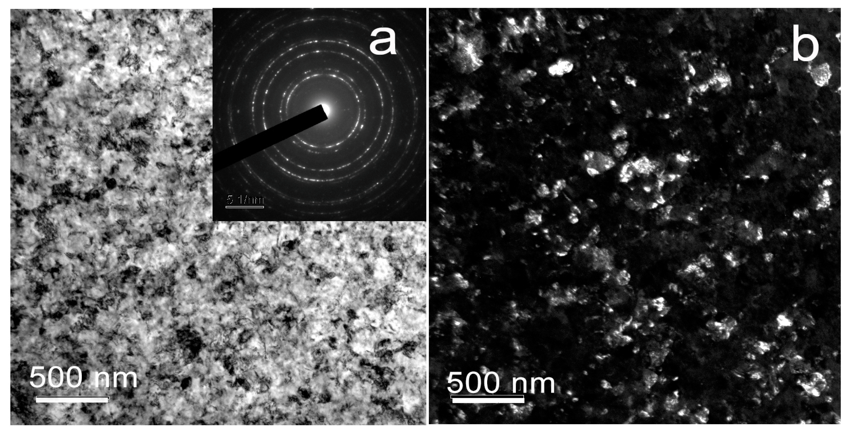
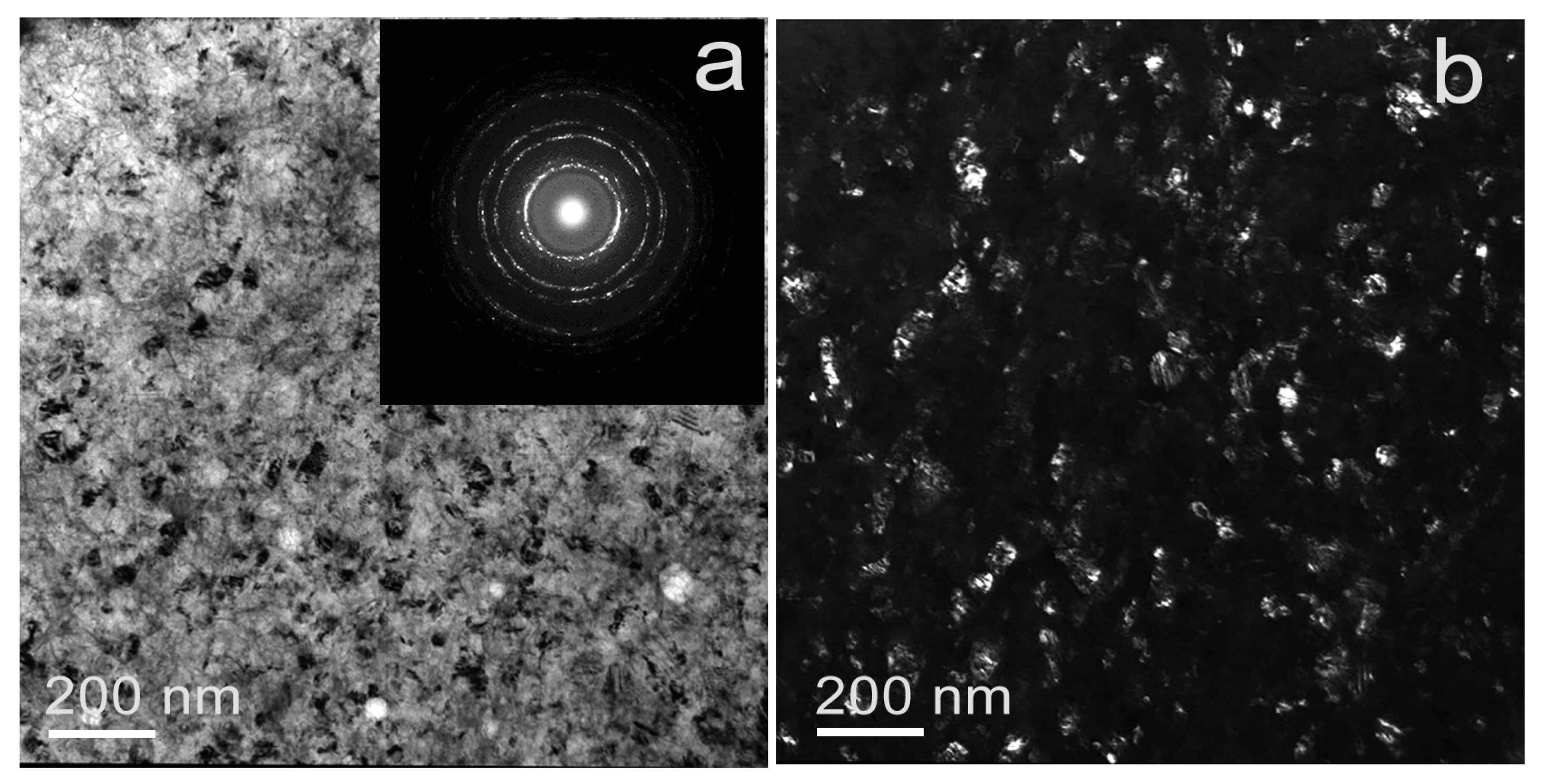
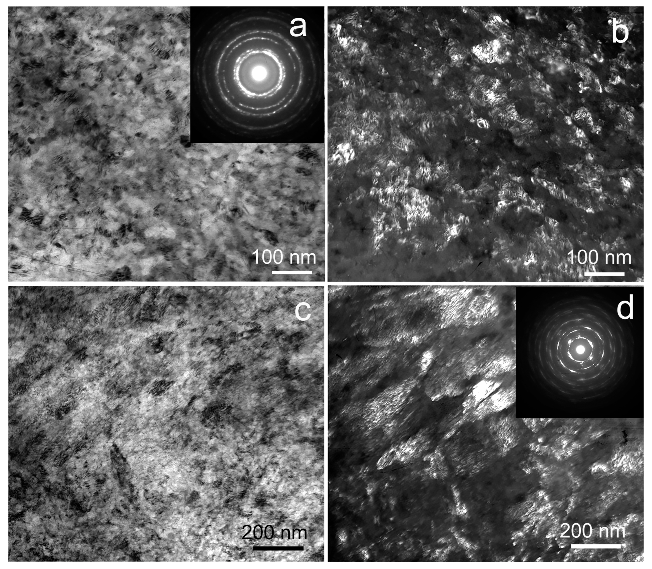
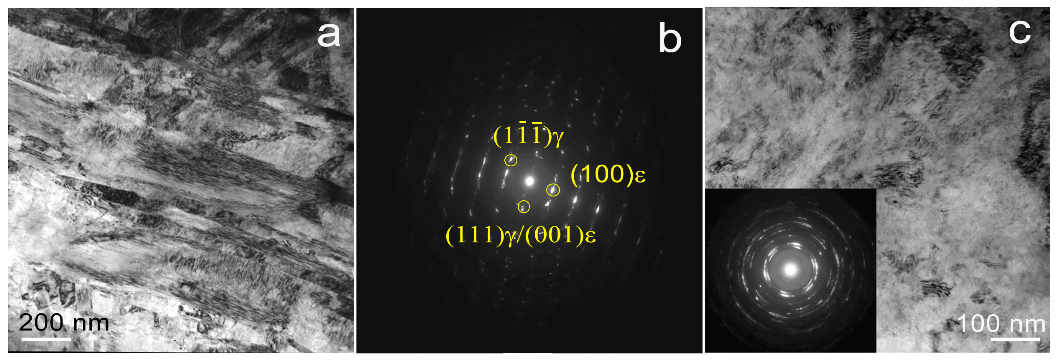
3.3. TEM Analysis of Fe-Mn Alloys After HPT

Transmission electron microscopy (TEM) confirmed and supplemented the X-ray structural studies of the structural and phase composition. TEM analysis revealed the formation of an austenitic ultrafine-grained grain-subgrain structure in the Fe-Mn alloy after HPT at a temperature of 300 °C (Figure 3), as indicated by the presence of individual re-flections in the ring selected area electron diffraction (SAED) pattern (Figure 3a (insert)). The average size of the structural elements was ~105 ± 4 nm.
In this case, TEM images of the Fe-Mn alloy structure after HPT at a temperature of 20 °C reveal a non-uniform predominantly martensitic structure of the alloy (Figure 4). In this structure, along with areas of fine-grained structure (Figure 4c) with large lattice distortions, coarser-grained areas are found (Figure 4b). Finer-grained areas are represented by an ultrafine-grained structure with an average size of structural elements of 103 ± 6 nm, and in areas with a larger structure, the formation of shear bands 150–1000 nm thick is revealed.
During the TEM analysis of the Fe-Mn-3.7Si alloy after HPT at 300 °C, a fully austenitic nanoscale grain-subgrain structure was found (Figure 5). In the Fe-Mn-3.7Si alloy, the average size of structural elements determined by the dark field (Figure 5b) was ~61 ± 2 nm.
The structure of the Fe-Mn-5Si alloy after the same treatment is very inhomogeneous (Figure 6). Thus, Figure 6a,c show two types of structure with different misorientation of grains or subgrains. Figure 6a shows an ultrafine-grained grain-subgrain structure that is confirmed, among other things, by the diffraction pattern in the inset. The structure in Figure 6 is coarser-grained with less distortion. In areas with an ultrafine-grained structure, the average size of structural elements is 52 ± 6 nm (Figure 6a,b). At the same time, areas with a larger structure are represented by structural elements with an average size of 181 ± 11 nm (Figure 6c,d).
During HPT at room temperature, the Fe-Mn-5Si alloy also undergoes a martensitic γ → ε transformation (Figure 7). The structure exhibits similar heterogeneity. Both regions with slight intragranular distortions and regions of the UFG structure with large lattice distortions are present (Figure 7c). TEM analysis reveals a small content of austenite (Figure 7b).

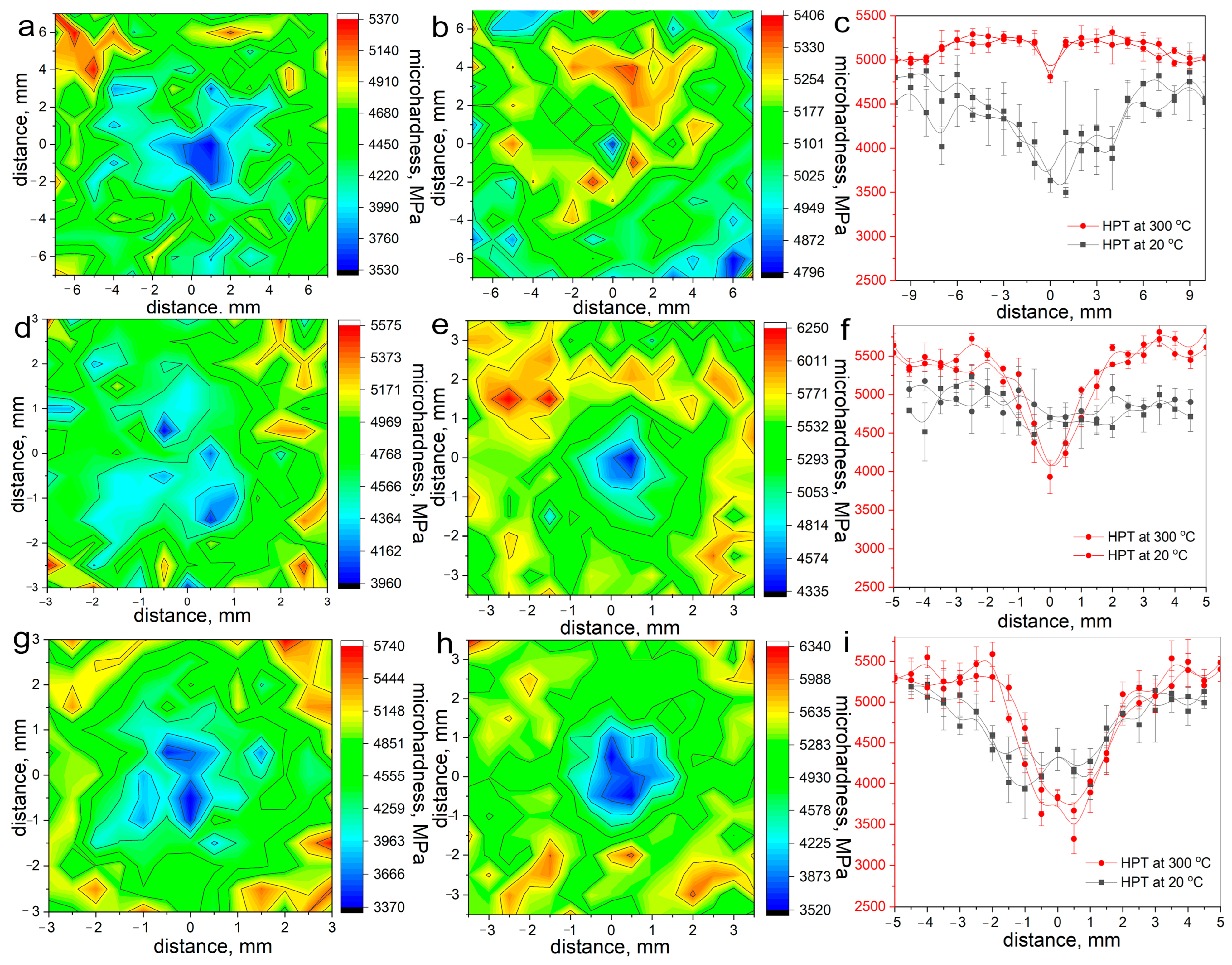
3.4. Microhardness Measurements of Fe-Mn Alloys After HPT

To assess the strength of the HPT-treated alloys, Vickers microhardness measurements (Figure 8) with the construction of microhardness distribution matrices over the sample surface and along two mutually perpendicular diameters were used. HPT at room temperature led to an increase in the microhardness in the Fe-Mn alloy at the middle of the radius to ~4500 MPa. With an increase in the silicon content, the microhardness slightly increased to ~4750 MPa and to ~5000 MPa in the Fe-Mn-3.7Si and Fe-Mn-5Si alloys, respectively.
The microhardness at the middle of the radius after HPT at 300 °C temperature was ~5250–5500 MPa. At the same time, since the two-phase and martensitic structure gave a large measurement error, it was not possible to confirm a statistically significant change in the microhardness. Thus, despite the different structural and phase states obtained as a result of HPT, the microhardness at the mid-radius of the samples was practically the same, which was a consequence of the mutual compensation of the properties of the phase and structural states of the alloy. It is noted that the difference between the microhardness in the center and the microhardness at the middle of the radius of the sample increased with increasing silicon content in the alloy, which is clearly shown in the graphs of the distribution of microhardness over two mutually perpendicular diameters (Figure 8c,f,i).

3.5. Corrosion Rate Measurement of Fe-Mn Alloys After HPT

3.5.1. Potentiodynamic Polarization

The corrosion properties of Fe-Mn alloys were assessed using electrochemical measurements by the potentiodynamic polarization (PDP) method. The PDP curves (Figure 9a–c) obtained after 20 min of open-circuit holding were almost identical, indicating that a stable potential had been achieved. Since alloys in different structural-phase states were obtained and investigated during this study, a detailed analysis made it possible to estimate the effect of these states on the corrosion rate.
Analysis of the PDP curves (Figure 9d) showed that alloys with a grain-subgrain austenitic nanostructure have the highest corrosion rate. The maximum corrosion rate was shown by the Fe-Mn-3.7Si alloy after HPT at a temperature of 300 °C with an average size of structural elements of 61 ± 2 nm (0.51 ± 0.02 mm/year). Increasing the average size of structural elements of the Fe-Mn alloy after the same treatment to 105 ± 4 nm slightly re-duces the degradation rate to 0.47 ± 0.03 mm/year. At the same time, alloys with a defective martensitic structure obtained by HPT at room temperature have a corrosion rate close to the corrosion rate of nanostructured austenite. However, those obtained during experiment corrosion rate of alloys with a martensitic and two-phase structure are characterized by a very large measurement error due to large structural heterogeneity. Nevertheless, it can be summarized that the refinement of austenitic alloys to nanoscale sizes reduces the corrosion resistance to the level of a less significantly refined defective martensitic structure.

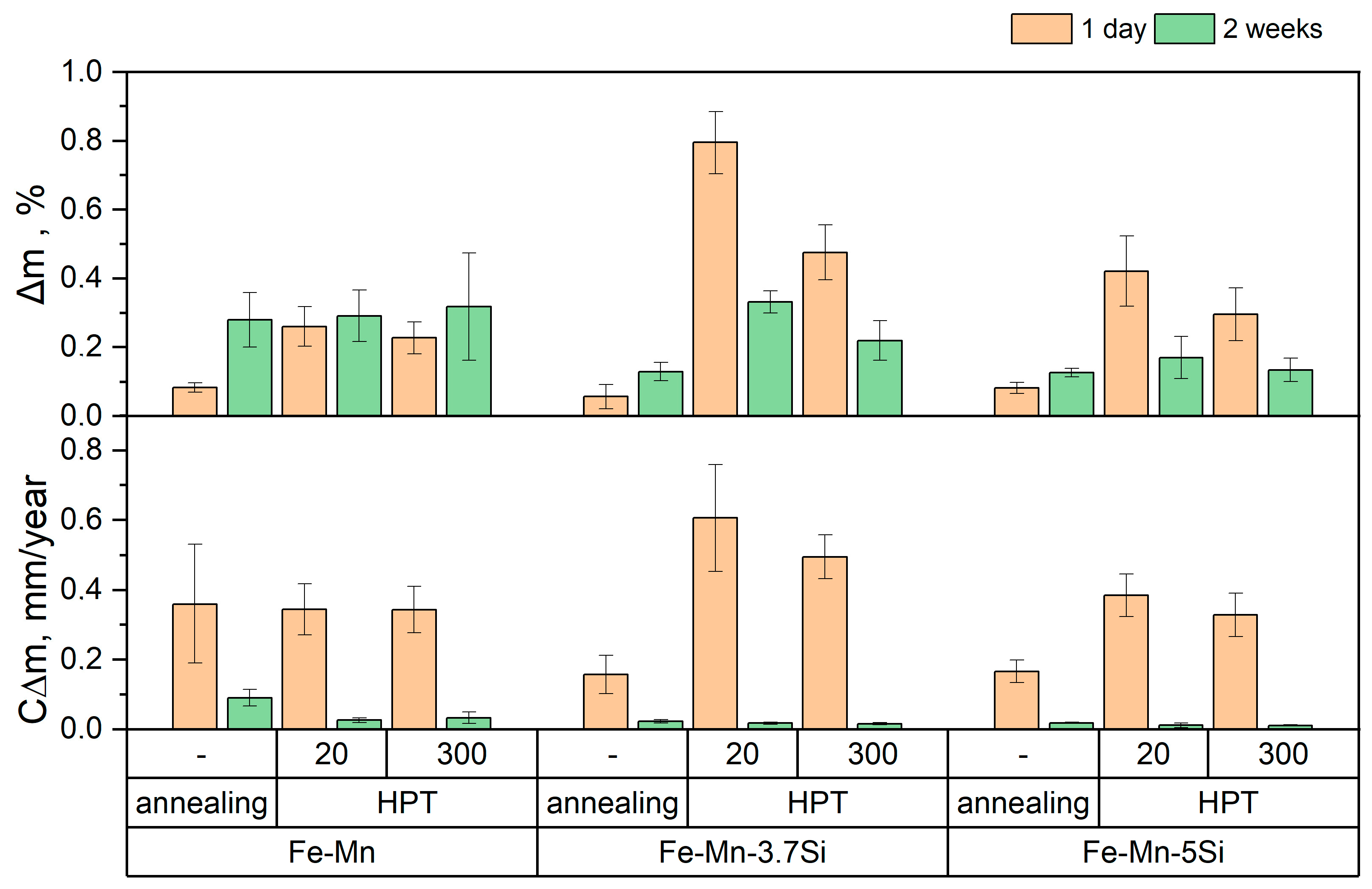
3.5.2. Mass Loss Measurements

Immersion corrosion tests, which consist of measuring the mass loss due to corrosion, confirmed the data of electrochemical studies during incubation in a culture medium for 1 day (Figure 10). Extending sample incubation in culture medium to 14 days leads to a notable decrease in corrosion rate because degradation byproducts create a barrier that inhibits further corrosive attack.
Figure 10 clearly shows a significant decrease in the degradation rate of Si alloys in the initial state relative to the Fe-Mn alloy. This effect is explained by the presence of annealing twins in the structure of silicon alloys. At the same time, a large measurement error in the mass loss ∆m of the Fe-Mn alloy may indicate sufficiently deep pitting damage, which complicates the removal of corrosion products from the surface of the sample. The measurement error is also introduced by the heterogeneity of the alloy structure after HPT, especially in the martensitic state. Some discrepancy in the corrosion rates determined by the two methods presented above can be explained by different testing media and conditions.

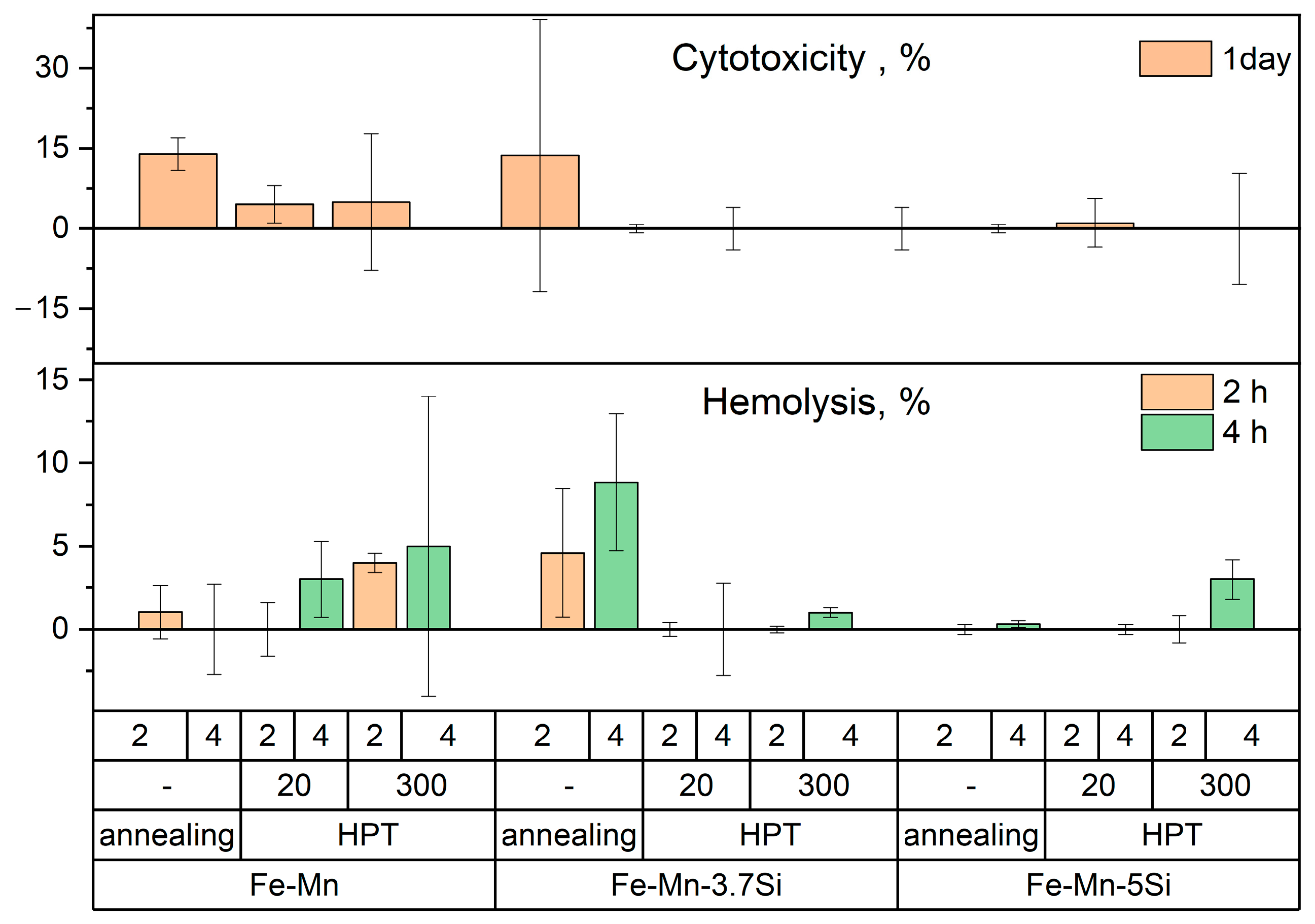
3.6. Biocompatibility In Vitro of Fe-Mn Alloys After Annealing and HPT

The conducted in vitro biocompatibility studies of Fe-30Mn, Fe-30Mn-3.7Si, and Fe-30Mn-5Si alloys after HPT showed that incubation of cells with all the studied alloy samples in the initial state and after HPT did not lead to a reliable increase in hemolysis and cytotoxicity compared to the control (Figure 11), where the cells were cultured under the same conditions, but without additional exposure to the samples. This indicates that the tested alloys meet the requirements for medical materials according to these safety criteria for biological objects [72,73].
Comparing the properties of alloys of different chemical compositions, one can see a tendency for a more intensive increase in hemolysis and cytotoxicity under the influence of incubation with samples based on Fe-Mn, which, however, was not reliably confirmed by statistical analysis methods during the experiments. Moreover, the obtained results also indicate that the presence of silicon in Fe-Mn alloys stimulates the tendency of increasing cell tolerance to the products of their biodegradation during the process of co-incubation.

4. Discussion

Different structural states of three Fe-Mn alloys were obtained in the HPT process at room temperature and 300 °C. After HPT at room temperature, refined fully martensitic structure was obtained in Fe-Mn-3.7Si and Fe-Mn-5Si alloys and ultrafine-grained two-phase structure (94.5% ε-martensite and 5.5% austenite) in Fe-Mn alloy. HPT at 300 °C resulted in ultrafine-grained two-phase structure (81.5% ε-martensite and 18.5% austenite) in Fe-Mn-5Si alloy and nanostructured austenitic state in Fe-Mn and Fe-Mn-3.7Si alloys. The obtained microstructures clearly show that increasing Si in the alloy promotes the martensitic transformation. Thus, adding 3.7% silicon to the Fe-Mn base after HPT at room temperature changed the two-phase structure to a fully martensitic one, and increasing the silicon content in the alloy to 5% after HPT at 300 °C changed the austenitic structure to a predominantly martensitic one (ε~81.5%) (Table 1).
It was found that the structure formation mechanism at HPT was initially determined by the deformation but is influenced by the Si content and deformation temperature. HPT at room temperature initially led to the martensitic transformation. A stronger martensitic structure was more difficult to refine and, as such, to deform. This can explain the presence of traces of austenite in the structure after HPT at room temperature of the alloy with Si (Figure 7). However, when the result of HPT is a two-phase structure, then first, apparently, the original austenite structure is refined, and only after applying higher strain degrees in the already refined austenite grain, ε-martensite is formed within the boundaries of this refined grain. This is confirmed by the values of microstrains in Table 1. The later the stages of strain-induced martensite formation, the less of it was in the two-phase structure and the more difficult its formation was. This is evidenced by the level of microstrains and the density of dislocations of both Fe-Mn and Fe-Mn-5Si alloys in the two-phase state (Table 1). Thus, in the structure of the Fe-Mn-5Si alloy with 81.5% ε-martensite, the maximum level of microstrain of 0.42% was obtained, exceeding the value of microstrain of 0.361% in the Fe-Mn alloy after HPT at 20 °C (94.5% ε-martensite). The values of microstrain in alloys Fe-Mn-5Si and Fe-Mn-3.7Si with the martensitic structure after HPT at 20 °C were equal to 0.192%. At the same time, the level of microdeformation in austenite with a decrease in its amount also decreases from 0.36% at a dislocation density of 5.13 × 1011 cm−2 in the structure of the Fe-Mn-5Si alloy after HPT at 300 °C to 0.241% at a dislocation density of 2.3 × 1011 cm−2 in the Fe-Mn alloy after HPT at room temperature. Competing structure formation processes consisting of grain refinement due to dislocation slip and the formation of ε-martensite caused the inhomogeneity of the two-phase structure (Figure 4 and Figure 6).
It is noted that with an increase in the silicon content after HPT at room temperature, the microhardness value at the middle of the sample radius increases slightly from ~4500 MPa of the microhardness value of the alloy without silicon to ~4750 MPa and to ~5000 MPa in the Fe-Mn-3.7Si and Fe-Mn-5Si alloys, respectively (Figure 8). Such an increase in microhardness can be explained by the difference in the fine structure of martensite. In [74], it was found that an increase in the silicon content in medium-manganese steel leads to a decrease in the crystallite size in martensite and, accordingly, to an increase in the number of martensite lath boundaries, as well as to an increase in the dislocation density.
The same reason lies in the increase in the difference between the microhardness values in the center and at the edge of the samples in the martensitic state with an increase in the silicon content (Figure 8c,f,i). Such structural inhomogeneity is characteristic only of samples in the martensitic and predominantly martensitic state. Despite the higher microhardness values (~5500 MPa), the structure in the fully austenitic state is uniformly refined. Therefore, the reason for the heterogeneity is most likely not the slippage of the samples during deformation, but the lack of plasticity induced by the transformation, which ends the faster, the more silicon is in the alloy. Nevertheless, despite some heterogeneity of the obtained microstructures, extremely refined structural states of these alloys were obtained in the work. It is important to note that this level is much higher than the level of microhardness of the alloys in the initial state. Considering that for Fe-Mn, Fe-Mn-3.7Si and Fe-Mn-5Si alloys in the initial state the microhardness was equal to 1559 MPa, 2632 MPa, and 2316 MPa, respectively, it is clearly seen that by the end of deformation they have exhausted their plasticity resource.
It is not surprising that the extremely deformed austenitic nanostructures in Fe-Mn-3.7Si and Fe-Mn alloys after HPT at 300 °C with an average size of structural elements of 61 ± 2 nm and ~105 ± 4 nm, respectively, show approximately equal electrochemical corrosion rates of 0.51 ± 0.02 mm/year and 0.47 ± 0.03 mm/year, respectively (Figure 9d). It is worth noting that the martensitic structure itself is defective and less corrosion resistant. Thus, in [75] it is noted that the deterioration of passive behavior with an increase in the amount of martensite changes the corrosion damage of the alloy. While the corrosion damage of austenite is manifested mainly by surface pitting, the damage of the martensitic phase takes the form of micropitting and selective corrosion of martensitic plates [75]. Therefore, even slightly refined martensite shows a corrosion rate comparable to nanostructured austenite.
Thus, having traced the dependence of microhardness and the rate of electrochemical corrosion on the change in microstructure, one can note their strong dependence on the structural and phase state. At the same time, the values of these characteristics for different alloys after various treatments are very close as a result of compensation for the microstructure refinement and phase state.
It should also be noted that Fe-Mn-Si alloys are biocompatible. It is proven in studies of cytotoxicity and hemolysis induced by them in vitro, especially after HPT. Studies of non-metallic biomaterials have demonstrated excellent properties including osteogenesis and angiogenesis of silicon and its compounds [76,77]. It is also known that in a culture medium, silicon, which is part of biomaterials, forms functional groups Si-OH on the surfaces, thereby causing the nucleation of apatites. Taking into account the high density of crystal structure defects in deformed alloys, including boundaries of structural elements, which implies an increased density of places where the boundaries emerge on the surface of the samples, it is possible to assume an increased release of silicon ions onto the surface, which can neutralize the negative effect caused by the Fe-Mn base.

5. Conclusions

In the presented work, various structural-phase states of the Fe-Mn alloys were formed using the HPT method at room temperature and at 300 °C for a comprehensive study of changes in mechanical and functional characteristics of these alloys.
  • HPT results in significant refinement of the structure down to 50 nm and the formation of strain-induced martensite in alloys.
  • It was found that the deformation-induced structural refinement mechanism is determined by the deformation but is influenced by the Si content and deformation temperature.
  • Si promotes the occurrence of martensitic transformation in the alloys, as indicated by the phase composition of the alloys within one treatment.
  • Almost identical microhardness of the studied alloys was noted as a result of compensation of their phase and structural state at the same HPT temperature.
  • The maximum rate of electrochemical corrosion was obtained in alloys with a grain-subgrain nanosized austenitic structure in the Fe-Mn-3.7Si alloy (0.51 ± 0.02 mm/year) and in the Fe-Mn alloy (0.47 ± 0.03 mm/year) after HPT at 300 °C.
  • It was found that alloys with a defective martensitic structure, which have a coarser grain structure, degrade at rates close to those of nanosized austenite.
  • The study of cytotoxicity and induced hemolysis in vitro showed that Fe-Mn, Fe-Mn-3.7Si, and Fe–Mn-5Si alloys after HPT can be characterized as biocompatible, and also allowed to suggest an increase in the tolerance of blood cells to the products of bioresorption of alloys containing Si.

Author Contributions

Conceptualization, N.M. and O.R.; methodology, N.A., S.D. and M.K.; software, G.R., N.T., A.B., A.T. and I.S.; validation, O.R., E.L., N.A. and N.M.; formal analysis, N.M., E.L. and O.R.; investigation, O.R., N.M., N.A., G.R., N.T., I.S. and D.T.; resources, A.T., P.S. and P.D.; data curation, O.R., N.M. and N.A.; writing—original draft preparation, O.R., G.R., N.M. and N.A.; writing—review and editing, G.R., I.S., N.A. and N.M.; visualization, O.R. and N.A.; supervision, M.K. and A.B.; project administration, O.R.; funding acquisition, N.M. All authors have read and agreed to the published version of the manuscript.

Funding

This research was funded by the Russian Science Foundation (Grant #25-23-00208).

Data Availability Statement

All the data required to reproduce these experiments are present in this article.

Acknowledgments

This study of the microstructure was carried out using research equipment from the Shared Facility Center at P.N. Lebedev Physical Institute of RAS “Center for the Study of High-Temperature Superconductors and Other Strongly Correlated Electronic Systems”. TEM analysis was carried out on the equipment of the Shared Facility Center “Materials Science and Metallurgy”.

Conflicts of Interest

The authors declare no conflicts of interest.

References

  1. Saha, S.; Roy, S. Metallic Dental Implants Wear Mechanisms, Materials, and Manufacturing Processes: A Literature Review. Materials 2023, 16, 161. [Google Scholar] [CrossRef]
  2. Yazdanpanah, A.; De Pietri, A.; Hjal, A.B.; Khodabakhshi, M.; Biasiolo, L.; Dabalà, M. Electrochemical and localized corrosion characteristics of kolsterised and DLC-coated 316LVM stainless steel for biomedical applications. Appl. Surf. Sci. 2025, 693, 162808. [Google Scholar] [CrossRef]
  3. Rybalchenko, O.; Anisimova, N.; Martynenko, N.; Rybalchenko, G.; Tokar, A.; Lukyanova, E.; Prosvirnin, D.; Gorshenkov, M.; Kiselevskiy, M.; Dobatkin, S. Effect of Nanostructuring on Operational Properties of 316LVM Steel. Metals 2023, 13, 1951. [Google Scholar] [CrossRef]
  4. Gatto, M.L.; Santoni, A.; Santecchia, E.; Spigarelli, S.; Fiori, F.; Mengucci, P.; Cabibbo, M. The Potential of Duplex Stainless Steel Processed by Laser Powder Bed Fusion for Biomedical Applications: A Review. Metals 2023, 13, 949. [Google Scholar] [CrossRef]
  5. Rybalchenko, O.; Torganchuk, V.; Rybalchenko, G.; Martynenko, N.; Lukyanova, E.; Tokar, A.; Prosvirnin, D.; Yusupov, V.; Dobatkin, S. Effect of Rotary Swaging on Microstructure and Properties of Cr-Ni-Ti Austenitic Stainless Steel. Metals 2023, 13, 1760. [Google Scholar] [CrossRef]
  6. Avanzini, A. Fatigue Behavior of Additively Manufactured Stainless Steel 316L. Materials 2023, 16, 65. [Google Scholar] [CrossRef]
  7. Rybalchenko, O.V.; Anisimova, N.Y.; Kiselevsky, M.V.; Belyakov, A.N.; Tokar, A.A.; Terent’ev, V.F.; Prosvirnin, D.V.; Rybalchenko, G.V.; Raab, G.I.; Dobatkin, S.V. The influence of ultrafine-grained structure on the mechanical properties and biocompatibility of austenitic stainless steels. J. Biomed. Mater. Res. 2020, 108, 1460–1468. [Google Scholar] [CrossRef]
  8. Ryklina, E.; Polyakova, K.; Komarov, V.; Murygin, S.; Konopatsky, A.; Andreev, V.; Ulanov, A. On Transformation and Stress–Strain–Temperature Behavior of Fine-Grained Ni-Rich NiTi Wire vs. Aging Mode. Metals 2025, 15, 3. [Google Scholar] [CrossRef]
  9. Pal, S.; Velay, X.; Saleem, W. Assessing the Corrosive Effects of Unmelted Particles in Additively Manufactured Ti6Al4V: A Study in Simulated Body Fluid. Alloys 2024, 3, 257–268. [Google Scholar] [CrossRef]
  10. Kannan, A.R.; Shanmugam, N.S.; Rajkumar, V.; Vishnukumar, M.; Channabasavanna, S.G.; Oh, J.; Dat, T.T.K.; Yoon, J. Microstructure, Mechanical Properties and Corrosion Performance of Laser-Welded NiTi Shape Memory Alloy in Simulated Body Fluid. Materials 2024, 17, 4801. [Google Scholar] [CrossRef]
  11. Ryklina, E.; Murygin, S.; Komarov, V.; Polyakova, K.; Resnina, N.; Andreev, V. On Structural Sensitivity of Young’s Modulus of Ni-Rich Ti-Ni Alloy. Metals 2023, 13, 1428. [Google Scholar] [CrossRef]
  12. Baranova, A.; Dubinskiy, S.; Vvedenskaya, I.; Bazlov, A.; Tabachkova, N.; Sheremetyev, V.; Teplyakova, T.; Strakhov, O.; Prokoshkin, S. Evolution of Structure and Texture Formation in Thermomechanically Treated Ti-Zr-Nb Shape Memory Alloys. Appl. Sci. 2024, 14, 3647. [Google Scholar] [CrossRef]
  13. Lu, Y.J.; Zhang, Z.L.; Liu, Y.J.; Yu, C.; Zhang, X.; Liu, X.C. Improving mechanical properties and corrosion behavior of biomedical Ti-3Zr-2Sn-3Mo-25Nb alloy through laser surface remelting. Surf. Coat. Technol. 2024, 490, 131135. [Google Scholar] [CrossRef]
  14. Bortolini, C., Jr.; Carobolante, J.P.A.; Timokhina, I.; Caporalli Filho, A.; Rosifini Alves, A.P. Processing of the Ti25Ta25Nb3Sn Experimental Alloy Using ECAP Process for Biomedical Applications. J. Manuf. Mater. Process. 2023, 7, 201. [Google Scholar] [CrossRef]
  15. Thapa, M.; Sun, Y.; Keaty, B.; Takoudis, C.; Mathew, M. Corrosion risk analysis of CoCrMo alloy as a function of microstructure: Biomedical applications. Surf. Coat. Technol. 2025, 497, 131757. [Google Scholar] [CrossRef]
  16. da Silva Batista, B.; Rodrigues, S.F.; Cardoso, J.L.; Goncalves Rodrigues, M.V.; de Menezes, A.S.; Santos-Oliveira, R.; da Silva, L.M.; Rebêlo Alencar, L.M. Tantalum’s role in the microstructure and its influence on corrosive behavior in Co-Cr-Ta alloy. J. Alloys Compd. 2025, 1010, 177216. [Google Scholar] [CrossRef]
  17. Li, H.; Zhang, S.; Liang, J.; Hu, M.; Yang, Y. Effect of Ti on Characterization and Properties of CoCrFeNiTix High Entropy Alloy Prepared Via Electro-Deoxidization of the Metal Oxides and Vacuum Hot Pressing Sintering Process. Materials 2023, 16, 1547. [Google Scholar] [CrossRef]
  18. Hussain, M.; Khan, S.M.; Al-Khaled, K.; Ayadi, M.; Abbas, N.; Chammam, W. Performance analysis of biodegradable materials for orthopedic applications. Mater. Today Commun. 2022, 31, 103167. [Google Scholar] [CrossRef]
  19. Heiden, M.; Walker, E.; Stanciu, L. Magnesium, Iron and Zinc Alloys, the Trifecta of Bioresorbable Orthopaedic and Vascular Implantation—A Review. J. Biotechnol. Biomater. 2015, 5, 178. [Google Scholar] [CrossRef]
  20. Cheng, J.; Liu, B.; Wu, Y.H.; Zheng, Y.F. Comparative in vitro Study on Pure Metals (Fe, Mn, Mg, Zn and W) as Biodegradable Metals. J. Mater. Sci. Technol. 2013, 29, 619–627. [Google Scholar] [CrossRef]
  21. Zhao, H.; Cheng, J.; Zhao, C.; Wen, M.; Wang, R.; Wu, D.; Wu, Z.; Yang, F.; Sheng, L. The Recent Developments of Thermomechanical Processing for Biomedical Mg Alloys and Their Clinical Applications. Materials 2025, 18, 1718. [Google Scholar] [CrossRef]
  22. Martynenko, N.S.; Anisimova, N.Y.; Rybalchenko, O.V.; Kiselevskiy, M.V.; Rybalchenko, G.; Straumal, B.; Temralieva, D.; Mansharipova, A.T.; Kabiyeva, A.O.; Gabdullin, M.T.; et al. Rationale for Processing of a Mg-Zn-Ca Alloy by Equal-Channel Angular Pressing for Use in Biodegradable Implants for Osteoreconstruction. Crystals 2021, 11, 1381. [Google Scholar] [CrossRef]
  23. Xie, W.; Wu, C.-L.; Man, H.-C.; Chan, C.-W. Effect of Zinc Content on Powder Characteristics, Porosity, Microstructure, and Corrosion Behavior of SLM-Printed Mg-xZn-0.2Mn Alloys for Biomedical Applications. Coatings 2023, 13, 1876. [Google Scholar] [CrossRef]
  24. Yigit, O.; Gurgenc, T.; Dikici, B.; Kaseem, M.; Boehlert, C.; Arslan, E. Surface Modification of Pure Mg for Enhanced Biocompatibility and Controlled Biodegradation: A Study on Graphene Oxide (GO)/Strontium Apatite (SrAp) Biocomposite Coatings. Coatings 2023, 13, 890. [Google Scholar] [CrossRef]
  25. Venkateswarlu, B.; Sunil, B.R.; Kumar, R.S. Microstructure, mechanical properties and corrosion behavior of Rare Earths (RE) containing Mg-Zn alloy for biomedical applications. Mater. Today Proc. 2024, 102, 6–10. [Google Scholar] [CrossRef]
  26. Anisimova, N.; Martynenko, N.; Novruzov, K.; Rybalchenko, O.; Kiselevskiy, M.; Rybalchenko, G.; Straumal, B.; Salishchev, G.; Mansharipova, A.; Kabiyeva, A.; et al. Modification of Biocorrosion and Cellular Response of Magnesium Alloy WE43 by Multiaxial Deformation. Metals 2022, 12, 105. [Google Scholar] [CrossRef]
  27. Martynenko, N.; Anisimova, N.; Shinkareva, M.; Rybalchenko, O.; Rybalchenko, G.; Zheleznyi, M.; Lukyanova, E.; Temralieva, D.; Gorbenko, A.; Raab, A.; et al. Bioactivity Features of a Zn-1%Mg-0.1%Dy Alloy Strengthened by Equal-Channel Angular Pressing. Biomimetics 2023, 8, 408. [Google Scholar] [CrossRef] [PubMed]
  28. Martynenko, N.; Anisimova, N.; Rybalchenko, O.; Kiselevskiy, M.; Rybalchenko, G.; Tabachkova, N.; Zheleznyi, M.; Temralieva, D.; Bazhenov, V.; Koltygin, A.; et al. Structure, Biodegradation, and In Vitro Bioactivity of Zn–1%Mg Alloy Strengthened by High-Pressure Torsion. Materials 2022, 15, 9073. [Google Scholar] [CrossRef]
  29. Martynenko, N.; Anisimova, N.; Rybalchenko, O.; Kiselevskiy, M.; Rybalchenko, G.; Tabachkova, N.; Zheleznyi, M.; Prosvirnin, D.; Filonenko, D.; Bazhenov, V.; et al. Effect of High-Pressure Torsion on Microstructure, Mechanical and Operational Properties of Zn-1%Mg-0.1%Ca Alloy. Metals 2022, 12, 1681. [Google Scholar] [CrossRef]
  30. Moravej, M.; Mantovani, D. Biodegradable Metals for Cardiovascular Stent Application: Interests and New Opportunities. Int. J. Mol. Sci. 2011, 12, 4250–4270. [Google Scholar] [CrossRef]
  31. Hermawan, H.; Dubé, D.; Mantovani, D. Developments in metallic biodegradable stents. Acta Biomater. 2010, 6, 1693–1697. [Google Scholar] [CrossRef] [PubMed]
  32. Peuster, M.; Wohlsein, P.; Brugmann, M.; Ehlerding, M.; Seidler, K.; Fink, C.; Brauer, H.; Fischer, A.; Hausdorf, G. A novel approach to temporary stenting: Degradable cardiovascular stents produced from corrodible metal—Results 6–18 months after implantation into New Zealand white rabbits. Heart 2001, 86, 563–569. [Google Scholar] [CrossRef] [PubMed]
  33. Waksman, R.; Pakala, R.; Baffour, R.; Seabron, R.; Hellinga, D.; Tio, F.O. Short-Term Effects of Biocorrodible Iron Stents in Porcine Coronary Arteries. J. Interv. Cardiol. 2008, 21, 15–20. [Google Scholar] [CrossRef] [PubMed]
  34. Hermawan, H.; Dubé, D.; Mantovani, D. Development of Degradable Fe-35Mn Alloy for Biomedical Application. Adv. Mater. Res. 2006, 15–17, 107–112. [Google Scholar] [CrossRef]
  35. Schinhammer, M.; Hänzi, A.C.; Löffler, J.F.; Uggowitzer, P.J. Design strategy for biodegradable Fe-based alloys for medical applications. Acta Biomater. 2010, 6, 1705–1713. [Google Scholar] [CrossRef]
  36. Hermawan, H.; Purnama, A.; Dube, D.; Couet, J.; Mantovani, D. Fe–Mn alloys for metallic biodegradable stents: Degradation and cell viability studies. Acta Biomater. 2010, 6, 1852–1860. [Google Scholar] [CrossRef]
  37. Hermawan, H.; Alamdari, H.; Mantovani, D.; Dubé, D. Iron–manganese: New class of metallic degradable biomaterials prepared by powder metallurgy. Powder Metall. 2008, 51, 38–45. [Google Scholar] [CrossRef]
  38. Čapek, J.; Kubásek, J.; Vojtěch, D.; Jablonská, E.; Lipov, J.; Ruml, T. Microstructural, mechanical, corrosion and cytotoxicity characterization of the hot forged FeMn30(wt.%) alloy. Mater. Sci. Eng. C 2016, 58, 900–908. [Google Scholar] [CrossRef]
  39. Schinhammer, M.; Steiger, P.; Moszner, F.; Löffler, J.F.; Uggowitzer, P.J. Degradation performance of biodegradable Fe–Mn-C(-Pd) alloys. Mater. Sci. Eng. C 2013, 33, 1882–1893. [Google Scholar] [CrossRef]
  40. Moszner, F.; Sologubenko, A.S.; Schinhammer, M.; Lerchbacher, C.; Hänzi, A.C.; Leitner, H.; Uggowitzer, P.J.; Löffler, J.F. Precipitation hardening of biodegradable Fe–Mn–Pd alloys. Acta Mater. 2011, 59, 981–991. [Google Scholar] [CrossRef]
  41. Castro-Gamboa, S.; Garcia-Garcia, M.R.; Piñon-Zarate, G.; Rojas-Lemus, M.; Jarquin-Yañez, K.; Angel Herrera-Enriquez, M.; Fortoul, T.I.; Toledano-Magaña, Y.; Garcia-Iglesias, T.; Pestryakov, A.; et al. Toxicity of silver nanoparticles in mouse bone marrow-derived dendritic cells: Implications for phenotype. J. Immunotoxicol. 2019, 16, 54–62. [Google Scholar] [CrossRef] [PubMed]
  42. Mandal, S.; Ummadi, R.; Bose, M.; Balla, V.K.; Roy, M. Fe–Mn–Cu alloy as biodegradable material with enhanced antimicrobial properties. Mater. Lett. 2019, 237, 323–327. [Google Scholar] [CrossRef]
  43. Ma, Z.; Gao, M.; Na, D.; Li, Y.; Tan, L.; Yang, K. Study on a biodegradable antibacterial Fe-Mn-C-Cu alloy as urinary implant material. Mater. Sci. Eng. C 2016, 103, 109718. [Google Scholar] [CrossRef] [PubMed]
  44. Kadirov, P.; Zhukova, Y.; Gunderov, D.; Antipina, M.; Teplyakova, T.; Tabachkova, N.; Baranova, A.; Gunderova, S.; Pustov, Y.; Prokoshkin, S. Effect of Accumulative High-Pressure Torsion on Structure and Electrochemical Behavior of Biodegradable Fe-30Mn-5Si (wt.%) Alloy. Crystals 2025, 15, 351. [Google Scholar] [CrossRef]
  45. Rybalchenko, O.V.; Anisimova, N.Y.; Kiselevsky, M.V.; Rybalchenko, G.V.; Martynenko, N.S.; Bochvar, N.R.; Tabachkova, N.Y.; Shchetinin, I.V.; Shibaeva, T.V.; Konushkin, S.V.; et al. Effect of equal-channel angular pressing on structure and properties of Fe-Mn-C alloys for biomedical applications. Mater. Today Commun. 2022, 30, 103048. [Google Scholar] [CrossRef]
  46. Rybalchenko, O.; Anisimova, N.; Martynenko, N.; Rybalchenko, G.; Kiselevskiy, M.; Tabachkova, N.; Shchetinin, I.; Raab, A.; Dobatkin, S. Structure Optimization of a Fe–Mn–Pd Alloy by Equal-Channel Angular Pressing for Biomedical Use. Materials 2023, 16, 45. [Google Scholar] [CrossRef] [PubMed]
  47. Drevet, R.; Zhukova, Y.; Malikova, P.; Dubinskiy, S.; Korotitskiy, A.; Pustov, Y.; Prokoshkin, S. Martensitic Transformations and Mechanical and Corrosion Properties of Fe-Mn-Si Alloys for Biodegradable Medical Implants. Metall. Mater. Trans. A 2018, 49, 1006–1013. [Google Scholar] [CrossRef]
  48. Rybalchenko, O.; Anisimova, N.; Martynenko, N.; Rybalchenko, G.; Belyakov, A.; Shchetinin, I.; Lukyanova, E.; Chernogorova, O.; Raab, A.; Pashintseva, N.; et al. Biocompatibility and Degradation of Fe-Mn-5Si Alloy after Equal-Channel Angular Pressing: In Vitro and In Vivo Study. Appl. Sci. 2023, 13, 9628. [Google Scholar] [CrossRef]
  49. Heiden, M.; Kustas, A.; Chaput, K.; Nauman, E.; Johnson, D.; Stanciu, L. Stanciu. Effect of microstructure and strain on the degradation behavior of novel bioresorbable iron–manganese alloy implants. J. Biomed. Mater. Res. Part A 2015, 103, 738. [Google Scholar] [CrossRef] [PubMed]
  50. Sotoudeh Bagha, P.; Sheibani, S.; Khakbiz, M.; Ebrahimi-Barough, S.; Hermawan, H. Novel antibacterial biodegradable Fe-Mn-Ag alloys produced by mechanical alloying. Mater. Sci. Eng. C 2018, 88, 88–94. [Google Scholar] [CrossRef]
  51. Carluccio, D.; Xu, C.; Venezuela, J.; Cao, Y.; Kent, D.; Bermingham, M.; Demir, A.G.; Previtali, B.; Ye, Q.; Dargusch, M. Additively manufactured iron-manganese for biodegradable porous load-bearing bone scaffold applications. Acta Biomater. 2020, 103, 346–360. [Google Scholar] [CrossRef] [PubMed]
  52. Sharipova, A.; Swain, S.K.; Gotman, I.; Starosvetsky, D.; Psakhie, S.G.; Unger, R.; Gutmanas, E.Y. Mechanical, degradation and drug-release behavior of nano-grained Fe-Ag composites for biomedical applications. J. Mech. Behav. Biomed. Mater. 2018, 86, 240–249. [Google Scholar] [CrossRef] [PubMed]
  53. Allain, S.; Chateau, J.-P.; Bouaziz, O.; Migot, S.; Guelton, N. Correlations between the calculated stacking fault energy and the plasticity mechanisms in Fe-Mn-C alloys. Mater. Sci. Eng. A. 2004, 387–389, 158–162. [Google Scholar] [CrossRef]
  54. Grassel, O.; Kruger, L.; Frommeyer, G.; Meyer, L.W. High strength Fe–Mn–(Al, Si) TRIP/TWIP steels development—Properties—Application. Int. J. Plast. 2000, 16, 1391–1409. [Google Scholar] [CrossRef]
  55. Tian, X.; Zhang, Y.S. Effect of Si content on the stacking fault energy in γ-Fe–Mn–Si–C alloys: Part I. X-ray diffraction line profile analysis. Mater. Sci. Eng. A. 2009, 516, 73–77. [Google Scholar] [CrossRef]
  56. Sato, A.; Chishima, E.; Soma, K.; Mori, T. Shape memory effect in γ⇄ϵ transformation in Fe-30Mn-1Si alloy single crystals. Acta Metall. 1982, 30, 1177–1183. [Google Scholar] [CrossRef]
  57. Sato, A.; Chishima, E.; Yamaji, Y.; Mori, T. Orientation and composition dependencies of shape memory effect in Fe-Mn-Si alloys. Acta Metall. 1984, 32, 539–547. [Google Scholar] [CrossRef]
  58. Sato, A.; Yamaji, Y.; Mori, T. Physical properties controlling shape memory effect in Fe Mn Si alloys. Acta Metall. 1986, 34, 287–294. [Google Scholar] [CrossRef]
  59. Liu, B.; Zheng, Y.F.; Ruan, L. In vitro investigation of Fe30Mn6Si shape memory alloy as potential biodegradable metallic material. Mater. Lett. 2011, 65, 540–543. [Google Scholar] [CrossRef]
  60. Fântânariu, M.; Trinca, L.C.; Solcan, C.; Trofin, A.; Strungaru, S.; Sindilar, E.V.; Plavan, G.; Stanciu, S. A new Fe–Mn–Si alloplastic biomaterial as bone grafting material: In vivo study. Appl. Surf. Sci. 2015, 352, 129–139. [Google Scholar] [CrossRef]
  61. Roman, A.M.; Geantă, V.; Cimpoes, R.; Munteanu, C.; Lohan, N.M.; Zegan, G.; Cernei, E.R.; Ionit, I.; Cimpoes, N.; Ioanid, N. In-vitro analysis of Fe-Mn-Si smart biodegradable alloy. Materials 2022, 15, 568. [Google Scholar] [CrossRef] [PubMed]
  62. Maruyama, T.; Kubo, H. 12-Ferrous (Fe-Based) Shape Memory Alloys (SMAs): Properties, Processing and Applications. In Shape Memory and Superelastic Alloys; Woodhead Publishing Series in Metals and Surface Engineering; Yamauchi, K., Ohkata, I., Tsuchiya, K., Miyazaki, S., Eds.; Woodhead Publishing: Sawston, UK, 2011; pp. 141–159. [Google Scholar]
  63. Prokoshkin, S.; Pustov, Y.; Zhukova, Y.; Kadirov, P.; Karavaeva, M.; Prosviryakov, A.; Dubinskiy, S. Effect of Thermomechanical Treatment on Structure and Functional Fatigue Characteristics of Biodegradable Fe-30Mn-5Si (wt %) Shape Memory Alloy. Materials 2021, 14, 3327. [Google Scholar] [CrossRef] [PubMed]
  64. Prokoshkin, S.; Pustov, Y.; Zhukova, Y.; Kadirov, P.; Dubinskiy, S.; Sheremetyev, V.; Karavaeva, M. Effect of Thermomechanical Treatment on Functional Properties of Biodegradable Fe-30Mn-5Si Shape Memory Alloy. Metall. Mater. Trans. A 2021, 52, 2024–2032. [Google Scholar] [CrossRef]
  65. Toker, S.M.; Gerstein, G.; Maier, H.J.; Canadinc, D. Effects of microstructural mechanisms on the localized oxidation behavior of NiTi shape memory alloys in simulated body fluid. J. Mater. Sci. 2017, 53, 948–958. [Google Scholar] [CrossRef]
  66. Venezuela, J.; Dargusch, M.S. Addressing the slow corrosion rate of biodegradable Fe-Mn: Current approaches and future trends. Curr. Opin. Solid State Mater. Sci. 2020, 24, 100822. [Google Scholar] [CrossRef]
  67. Gollapudi, S. Grain size distribution effects on the corrosion behaviour of materials. Corros. Sci. 2012, 62, 90–94. [Google Scholar] [CrossRef]
  68. Jiang, S.; Hewett, J.; Jones, I.P.; Connolly, B.J.; Chiu, Y.L. Effect of misorientation angle and chromium concentration on grain boundary sensitisation in an austenitic stainless steel. Mater. Char. 2020, 164, 110343. [Google Scholar] [CrossRef]
  69. Gerashi, E.; Alizadeh, R.; Langdon, T.G. Effect of crystallographic texture and twinning on the corrosion behavior of Mg alloys: A review. J. Magnes. Alloys 2022, 10, 313–325. [Google Scholar] [CrossRef]
  70. ASTM G59-972003; Standard Test Method for Conducting Potentiodynamic Polarization Resistance Measurements. ASTM International: West Conshohocken, PA, USA, 2006.
  71. ASTM G31-21; Standard Guide for Laboratory Immersion Corrosion Testing of Metals. ASTM International: West Conshohocken, PA, USA, 2004.
  72. Song, C.; Zhang, Z.; Wu, W.; Wang, H.; Sun, Z.; Yang, Y.; He, W.; Xu, J.; Xia, Y.; Yin, W.; et al. Effect of Si on the dislocation state within martensite of ultra-high strength hot-rolled medium Mn steel with good ductility. Mater. Sci. Eng. A 2023, 869, 144825. [Google Scholar] [CrossRef]
  73. ASTM F756-08; Standard Practice for Assessment of Hemolytic Properties of Materials. ASTM International: West Conshohocken, PA, USA, 2008.
  74. ISO 10993-5:1999; Biological Evaluation of Medical Devices—Part 5: Tests for In Vitro Cytotoxicity. International Organization for Standardization: Geneva, Switzerland, 1999.
  75. Frenck, J.-M.; Vollmer, M.; Niendorf, T. The effect of γ′-martensite on the corrosion resistance of an Fe-Mn-Al-Ni-Cr shape memory alloy in a sodium chloride solution. Mater. Lett. 2024, 365, 136408. [Google Scholar] [CrossRef]
  76. Wang, T.; Qian, S.; Zha, G.C.; Zhao, X.J.; Ding, L.; Sun, J.Y.; Li, B.; Liu, X.Y. Synergistic effects of titania nanotubes and silicon to enhance the osteogenic activity. Colloids Surf. B Biointerfaces 2018, 171, 419–426. [Google Scholar] [CrossRef] [PubMed]
  77. Fu, X.; Liu, P.; Zhao, D.; Yuan, B.; Xiao, Z.; Zhou, Y.; Yang, X.; Zhu, X.; Tu, C.; Zhang, X. Effects of nanotopography regulation and silicon doping on angiogenic and osteogenic activities of hydroxyapatite coating on titanium implant. Int. J. Nanomed. 2020, 15, 4171–4189. [Google Scholar] [CrossRef] [PubMed]
Figure 1. SEM images of the Fe-Mn alloy (a), Fe-Mn-3.7Si alloy (b), and Fe-Mn-5Si alloy (c) in the initial states.
Crystals 15 00424 g001
Figure 2. X-ray diffractions of the Fe-Mn alloys after HPT at 20 °C (a) and after HPT at 300 °C (b).
Crystals 15 00424 g002
Figure 3. TEM images of Fe-Mn alloy after HPT at 300 °C: (a) BF image with SAED pattern (insert), (b) DF image.
Crystals 15 00424 g003
Figure 4. TEM images of Fe-Mn alloy after HPT at 20 °C: (a) BF image; (b) DF1 image of CG area with SAED pattern (inset); (c) DF2 image of ultrafine-grained (UFG) area.
Crystals 15 00424 g004
Figure 5. TEM images of Fe-Mn-3.7Si alloy after HPT at 300 °C: (a) BF image with SAED pattern (insert), (b) DF image.
Crystals 15 00424 g005
Figure 6. TEM images of Fe-Mn-5Si alloy after HPT at 300 °C: (a,c) BF image with SAED pattern (insert (a)), (b,d) DF image with SAED pattern (insert (d)).
Crystals 15 00424 g006
Figure 7. TEM images of Fe-Mn-5Si alloy after HPT at 20 °C: (a,c) BF image with SAED pattern for UFG structure (insert (c)), (b) SAED pattern from (γ + ε) area Ø 600 nm.
Crystals 15 00424 g007
Figure 8. Microhardness of Fe-Mn alloys produced by HPT: (ac) Fe-Mn alloy; (df) Fe-Mn-3.7Si alloy; (gi) Fe-Mn-3.7Si alloy; (a,d,g) after HPT at 20 °C; (b,e,h) after HPT at 300 °C; (a,b,d,e,g,h) distribution over surface of an HPT sample; (c,f,i) distribution along the diameters.
Crystals 15 00424 g008
Figure 9. Corrosion properties (ac) PDP curves of the technically pure iron, Fe-Mn alloys in physiological saline solution at scan rate of 1 mV/s; (d) comparison of the PDP results.
Crystals 15 00424 g009
Figure 10. The evolution of corrosion parameters for Fe-Mn alloys in different processing states (annealed vs. HPT) during DMEM immersion after 1 and 14 days. CΔm represents corrosion rate and Δm indicates weight loss.
Crystals 15 00424 g010
Figure 11. Hemolysis and cytotoxicity of Fe-Mn alloys after annealing and HPT calculated as percentage relative to control.
Crystals 15 00424 g011
Table 1. Results of the X-ray line profile analysis of the Fe-Mn-Si alloys after HPT.
AlloysProcessingPhaseSpace Groupa, ÅContent, wt.%ε, %ρ, cm−2
Fe-MnInitialγ225: Fm 3 ¯ m3.60880(6)100(3)0.025(5)1 × 10⁹
HPT at 20 °C γ225: Fm 3 ¯ m3.60510(16)5.5(3)0.241(15)2.3 × 10¹¹
ε194: P63/mmc2.5386(3)
2.5386(3)
4.0980(3)
94.5(3)0.361(4)-
HPT at 300 °Cγ225: Fm 3 ¯ m0.306(7)100(5)0.342(4)3.7 × 10¹¹
Fe-Mn-3.7SiInitialγ225: Fm 3 ¯ m3.60482(2)100(5)0.0144(15)1 × 10⁹
HPT at 20 °C ε194: P63/mmc2.5432(3)
2.5432(3)
4.1191(3)
100(5)0.191(7)1.44 × 10¹¹
HPT at 300 °Cγ225: Fm 3 ¯ m3.5951(2)100(6)0.254(5)2.55 × 10¹¹
Fe-Mn-5SiInitialγ225: Fm 3 ¯ m3.60413(10)1000.044(2)1 × 10⁹
HPT at 20 °C ε194: P63/mmc2.5448(3)
2.5448(3)
4.1252(2)
1000.192(7)1.46 × 10¹¹
HPT at 300 °Cγ225: Fm 3 ¯ m3.5987(3)18.5(10)0.36(2)5.13 × 10¹¹
ε194: P63/mmc2.5459(9)
2.5459(9)
4.1512(9)
81.5(10)0.42(5)-
Disclaimer/Publisher’s Note: The statements, opinions and data contained in all publications are solely those of the individual author(s) and contributor(s) and not of MDPI and/or the editor(s). MDPI and/or the editor(s) disclaim responsibility for any injury to people or property resulting from any ideas, methods, instructions or products referred to in the content.

