Article

Unveiling the Strengthening and Ductility Mechanisms of a CoCr0.4NiSi0.3 Medium-Entropy Alloy at Cryogenic Temperatures

1
School of Materials Science and Engineering, Shenyang Ligong University, Shenyang 110159, China
2
School of Materials Science and Engineering, Shenyang University of Technology, Shenyang 110870, China
*
Author to whom correspondence should be addressed.
Crystals 2025, 15(2), 170; https://doi.org/10.3390/cryst15020170
Submission received: 15 January 2025 / Revised: 7 February 2025 / Accepted: 8 February 2025 / Published: 10 February 2025

Abstract

:
Materials utilized in extreme environments, such as those necessitating protection and impact resistance at cryogenic temperatures, must exhibit high strength, ductility, and structural stability. However, most alloys fail to maintain adequate toughness at cryogenic temperatures, thereby compromising their safety during cryogenic temperature service. This study investigates the quasi-static mechanical properties of a CoCr0.4NiSi0.3 medium-entropy alloy (MEA) at room temperature, −75 °C, and −150 °C. The deformation behavior and mechanisms responsible for strengthening and toughening at reduced cryogenic temperatures are analyzed, revealing that decreasing cryogenic temperature enhances the strength of the as-cast MEA. Specifically, both the yield strength (YS) and ultimate tensile strength (UTS) of the MEA increase significantly with decreasing temperature during cryogenic tensile testing. Under tensile testing at −150 °C, the YS reaches 617.5 MPa, the UTS is 1055.0 MPa, and the elongation to fracture remains approximately 21.0% at both −150 °C and −75 °C. After cryogenic temperature tensile deformation, the matrix exhibits a dispersed distribution of nanoscaled tetragonal and orthorhombic phases, a coherent hexagonal close-packed phase, L12 phase and layered long-period stacking ordered (LPSO) structures, which are rarely observed in the cryogenic deformation of metals and alloys. The metastable phase evolution path of this MEA at cryogenic temperatures is closely associated with the decomposition of perfect dislocations into a/6<112> Shockley partial dislocations and their subsequent evolution at reduced cryogenic temperatures. At −75 °C, the a/6<112> Shockley partial dislocation interacts with the L12 phase to form antiphase boundaries (APBs) approximately 3 nm thick. At −150 °C, two phase transition paths from stacking faults (SFs) to nanotwins and LPSO occur, leading to the formation of layered LPSO structures and deformation-induced nanotwins. The dispersion of these coherent nanophases and nanotwins induced by the reduced stacking fault energy under cryogenic temperatures is the key factor contributing to the excellent balance of strength and plasticity in the as-cast MEA, providing an important basis for research on the cryogenic mechanical properties of CoCrNi-based MEAs.

1. Introduction

The strength and toughness of armor and shielding metallic materials serving in harsh environments such as cryogenic temperatures are two key factors that determine their mechanical performance. The preparation process of homogeneous steel armor is complex, and its mobility is poor; its performance potential is close to the limit. Therefore, it is of great significance to develop new armor materials suitable for cryogenic temperature applications that are safe, reliable, and easy to prepare. Seeking solutions in new alloys with a face-centered cubic (FCC) structure matrix, which exhibits good plasticity, has become a design concept to improve the cryogenic temperature performance of service alloys. Studies have shown that the dislocation movement in metals and alloys is substantially hindered at cryogenic temperatures, posing a significant challenge to maintaining their adequate ductility [1]. Additionally, the extreme cold can weaken metallic bonds, while deformation-induced increases in lattice friction stress may unexpectedly raise the yield strength [2], thereby severely affecting the mechanical properties and service safety of metal materials at cryogenic temperatures. Due to the atomic and modulus mismatch between different principal elements, high-entropy alloys (HEAs) exhibit pronounced element concentration fluctuations within their solid solution structures. These fluctuations contribute to enhanced comprehensive mechanical properties [3], making them a promising solution for addressing the low-temperature brittleness of alloys. Liu et al. [4] and Gludovatz et al. [5] investigated the quasi-static mechanical properties of FeCoNiCrMn (Cantor alloy) HEA at both room and cryogenic temperatures. Their experimental results demonstrate that as temperature decreases, the alloy exhibits significant increases in strength, fracture elongation, and strain hardening rate. Experimental studies on FeCoCrNiMn HEA [6,7,8] demonstrate that the yield strength of this HEA increases as temperature decreases, and the plastic deformation mechanism transitions from dislocation-dominated to twin-dominated. The increased twinning activity promotes uniform plastic deformation in the material [9], which is attributed to the low stacking fault energy (SFE) characteristic of FCC HEAs. The deformation behavior of metals and alloys with an FCC structure is notably influenced by both deformation temperature and SFE [10]. Huang et al. [11], through first-principles calculations, demonstrated that the SFE of FeCoNiCrMn exhibits a significant reduction as temperature decreases. Specifically, at room temperature, the SFE is approximately 21 mJ/m2, while at −273 °C, it drops to 3.41 mJ/m2.
CrCoNi-based MEAs have been demonstrated to exhibit superior strength and ductility at both room and cryogenic temperatures compared to Cantor alloy. Gludovatz et al. [5] investigated the quasi-static mechanical properties of CrCoNi MEA at room and cryogenic temperatures, revealing that the tensile strength and fracture elongation at −196 °C were significantly higher than those at room temperature. This finding overcomes the traditional trade-off between strength and toughness and delays necking initiation. The overall performance of CrCoNi-based MEAs was notably superior to that of FeCoNiCrMn HEA. Laplanche et al. [12] utilized transmission electron microscopy (TEM) to measure the width of extended dislocations, confirming that the SFE of NiCoCr is approximately 25% lower than that of FeCoNiCrMn.
Compared with FeCoNiCrMn, NiCoCr exhibits a higher yield strength and work hardening rate, allowing it to achieve the critical stress for twin initiation at a lower strain level. Consequently, twins can provide sustained work hardening through the dynamic Hall–Petch effect over a broader strain range, thereby enhancing the alloy’s overall mechanical properties. According to Gludovatz et al. [13], the SFE of CoCrNi MEA decreases to less than 0 mJ/m2 at −196 °C. As the deformation temperature decreases, the deformation mechanism transitions from dislocation slip to a cooperative deformation mode involving both twinning-induced plasticity (TWIP) and dislocation slip. Additionally, the transformation-induced plasticity (TRIP) effect becomes more pronounced when the temperature drops below a certain threshold. The fracture toughness of CoCrNi and other alloys generally increases as the temperature decreases, with lower temperatures typically resulting in superior toughness [13,14]. Incorporating Si into CoCrNi-based MEAs not only further reduces the SFE but also enhances lattice distortion, thereby improving mechanical properties at both ambient and cryogenic temperatures [14]. Studies on related alloy systems [14,15] consistently demonstrate that the deformation mechanism of CoCrNiSi0.3 MEA, containing 0.3 atomic percent silicon, differs from that of CoCrNi, exhibiting superior mechanical properties at both room and cryogenic temperatures. However, there is still potential for further optimization of the mechanical properties in this alloy system. According to the phase formation criterion proposed by Guo et al. [16], the phase formation in as-cast HEAs is significantly influenced by valence electron concentration (VEC). Specifically, when VEC exceeds 8, the stable phase is FCC, and a higher VEC enhances the alloy’s toughness [17]. For the quaternary CoCrNiSi0.3 MEA, reducing the Cr content, which has the lowest VEC among the components, can increase the overall VEC of the MEA, thereby improving its plasticity. First-principles calculations reveal a novel deformation mechanism for the Fe40Mn35Co20Cr5 biphase HEA with Si addition [18], indicating that Si atoms preferentially substitute Cr atoms. This substitution leads to increased lattice distortion and decreased SFE, thereby enhancing the balance between strength and plasticity. Theoretical calculations by the method of Guo et al. [16] show that the VEC of the CoCrNi MEA with superior mechanical properties is 8.33. In contrast, the newly designed CoCr0.4NiSi0.3 MEA, which has a reduced Cr content of 0.4 compared to the CoCrNiSi0.3 alloy, exhibits a comparable VEC of 8.37. Investigating the cryogenic temperature mechanical properties of CoCr0.4NiSi0.3 can deepen our understanding of the mechanical behavior and deformation mechanisms of CoCrNi-based MEAs. Studies have shown that after annealing [4,14], forging [13], rolling [5], and other pretreatments, the overall mechanical performance of CoCrNi-based H/MEAs is significantly enhanced compared to that of as-cast alloys [4,19]. Therefore, investigating the mechanical properties of as-cast CoCr0.4NiSi0.3 MEA with reduced Cr content is essential for expediting the development of CoCrNi-based alloys that demonstrate superior mechanical performance at cryogenic temperatures.
Due to the relatively low SFE, H/MEAs will undergo metastable phase transitions under varying conditions, such as temperature and stress, leading to the formation of ordered structures and other decomposition phases. Among these, long-period stacking ordered (LPSO) structures represent a special type of ordered structure characterized by complex long-range atomic arrangements. LPSO structures can be primarily categorized into rhombohedral (R) and hexagonal (H) Bravais lattices, with further classification based on the stacking period of atomic layers. These LPSO structures serve as excellent strengthening phases without compromising plasticity. They typically evolve from stacking faults (SFs) and have been observed during hot deformation and tensile testing at elevated temperatures in CoCrNi-based MEAs [20,21,22]. The L12 phase is consistently observed in Ni-based superalloys, where it exhibits excellent high-temperature mechanical properties and maintains coherence with the matrix. In FCC multi-principal alloys, the SFE decreases after annealing following deformation of CoCrNi-based alloys [23], or after adding alloying elements such as Ti, Nb, Ta, Mo, or W [24]. The mechanical properties at both ambient and elevated temperatures are significantly enhanced due to the precipitation of the L12 phase. The formation of L12 superlattice in these alloys is closely linked to the evolution of planar defects during deformation [25]. Notably, studies on cryogenic temperature deformation of as-cast H/MEAs seldom report the presence of the ordered L12 phase.
SFs and twins in FCC HEAs serve as primary channels for phase transformation from the FCC matrix to secondary phases during deformation across various alloy systems and temperatures. This transformation process involves multiple strengthening mechanisms. Therefore, this study conducted quasi-static tensile tests on CoCr0.4NiSi0.3 HEA at both room and cryogenic temperatures to investigate microstructure evolution and explore deformation mechanisms at cryogenic temperatures, thereby elucidating the strengthening and toughening mechanisms of CoCrNi-based HEAs with low SFEs.

2. Experimental

In this study, the MEA with a nominal composition of CoCr0.4NiSi0.3 (at.%), as shown in Table 1, was synthesized via vacuum suspension induction melting. High-purity raw materials of Co, Cr, Ni, and Si (purity ≥ 99.95 wt.%) were melted four times at 1700 °C to produce 5 kg ingots, ensuring chemical homogeneity. Subsequently, an alloy plate with a thickness of 16 mm was cast under an argon atmosphere and cooled to room temperature within 30 min. The dog-bone-shaped nonstandard quasi-static tensile samples were machined from the alloy plate via wire electrical discharge machining (WEDM) and subsequently ground and polished to achieve a surface roughness of ± 1.6 μm. The standard gauge dimensions for the cryogenic temperature tensile samples were 10 × 2.0 × 1.5 mm3, while those for the room-temperature tensile samples were 15 × 2.0 × 1.5 mm3. Quasi-static tensile mechanical tests were conducted at −150 °C, −75 °C, and room temperature using an AG-Xplus 50kN universal testing machine. For each condition, three replicate tests were performed. The samples were placed in a liquid nitrogen cooling device attached to the testing machine, where they were cooled to the desired temperature, held at that temperature for 10 min, and subsequently subjected to tensile testing. The crosshead displacement rate was set at 0.25 mm/min before yielding and increased to 1.75 mm/min after yielding.
Phase analysis of the samples was conducted using X-ray diffraction (XRD) with a Rigaku SmartLab SE diffractometer equipped with a Cu Kα radiation source. The scan rate was set at 5°/min over a 2θ range of 5° to 90°. A Thermo Fisher Apreo 2C field emission scanning electron microscope (FE-SEM) equipped with a symmetric S2 probe was utilized to characterize and analyze the microstructure and chemical composition of the tested samples. Image quality (IQ), grain boundaries (GBs), and coincident site lattice (CSL) diagrams were extracted from EBSD data for detailed analysis. The EBSD step size was set to 1 µm. Thin slices, with a thickness of less than 0.3 mm, were obtained via WEDM. Ultra-thin slices, with a thickness of less than 70 nm, were prepared by grinding and polishing to form Φ3 mm samples. TEM samples were prepared via the Gatan 695 precision ion milling technique. Microstructural characterization was conducted using an FEI Talos F200X G2 field emission TEM (FE-TEM) operated at an acceleration voltage of 200 kV.

3. Results and Discussion

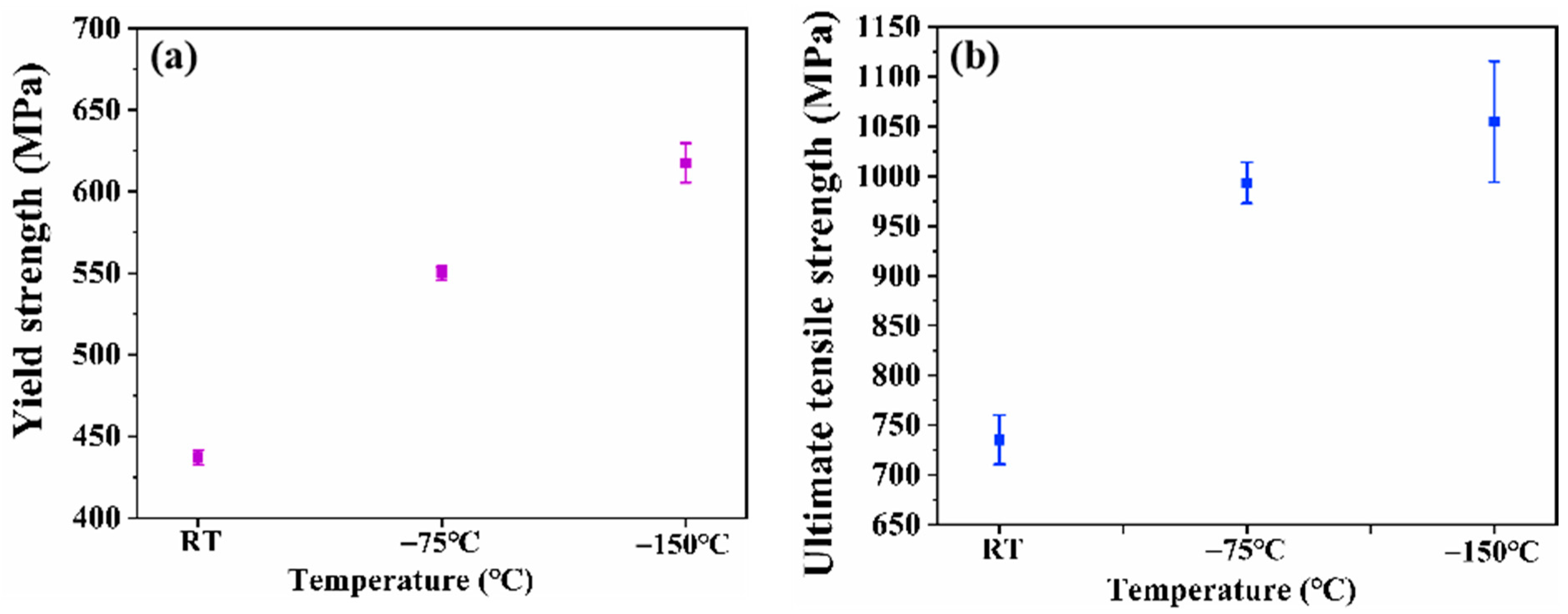
3.1. The Mechanical Properties

Figure 1a,b illustrate the engineering stress-strain curves of the as-cast CoCr0.4NiSi0.3 MEA at room temperature, −75 °C, and −150 °C, along with the corresponding elongation to fracture (EF) obtained from tensile tests. Table 2 provides a comparison of the yield strength (YS), ultimate tensile strength (UTS), and EF for the as-cast CoCr0.4NiSi0.3 MEA at room and cryogenic temperatures. Figure 1a and Figure 2 and Table 2 demonstrate that the YS and UTS of the as-cast alloy increase with decreasing deformation temperature after cryogenic tensile testing. Specifically, the YS rises from 437.0 MPa at room temperature to 617.5 MPa at −150 °C, while the UTS increases from 825.0 MPa at room temperature to 1055.0 MPa at −150 °C. EF exhibited a high level of tensile deformation performance at cryogenic temperatures, while the MEA showed an outstanding strain hardening capability, achieving a strength increment in the range of 338~443 MPa (σUTSy) at both room and cryogenic temperatures in its as-cast state. This highlights the alloy’s excellent cryogenic strength and ductility. The mechanical properties of the as-cast alloy at −75 °C and −150 °C are superior to those at room temperature, with an increasing trend observed as the deformation temperature decreases.

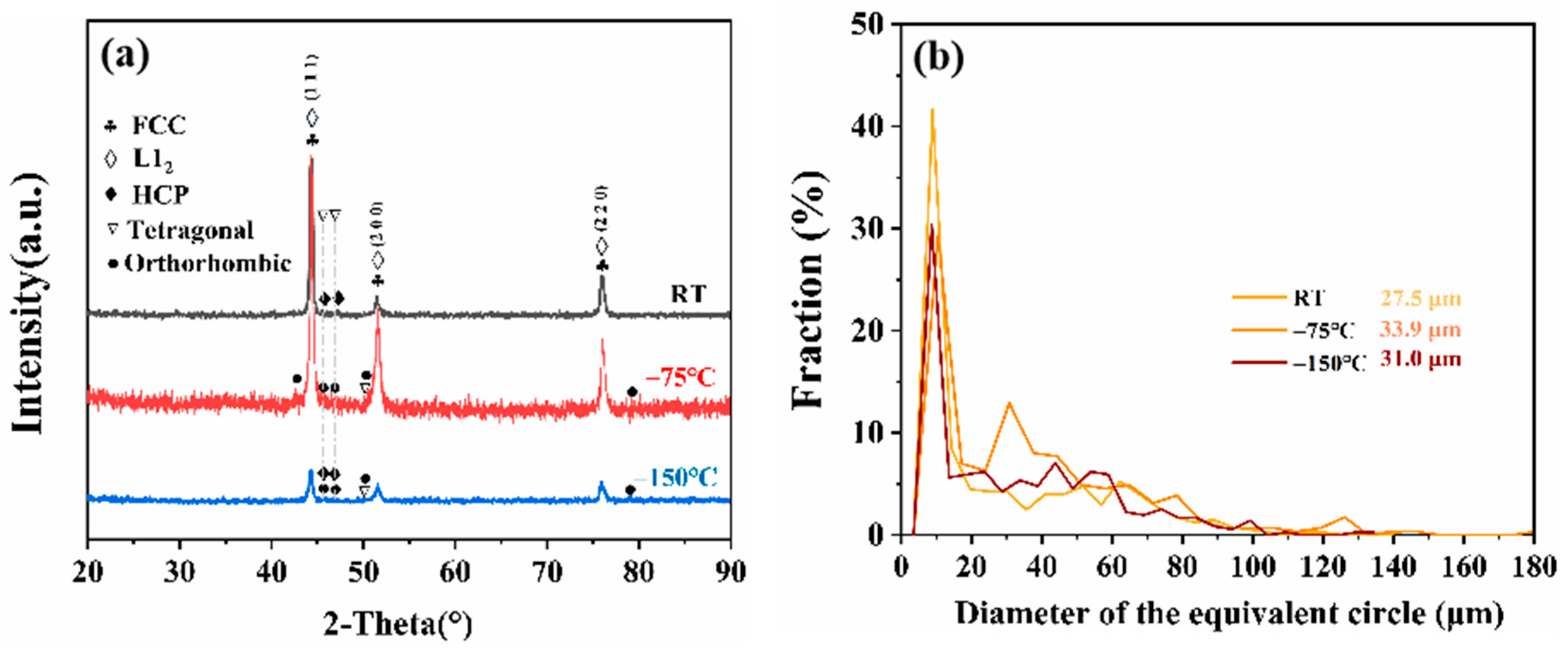
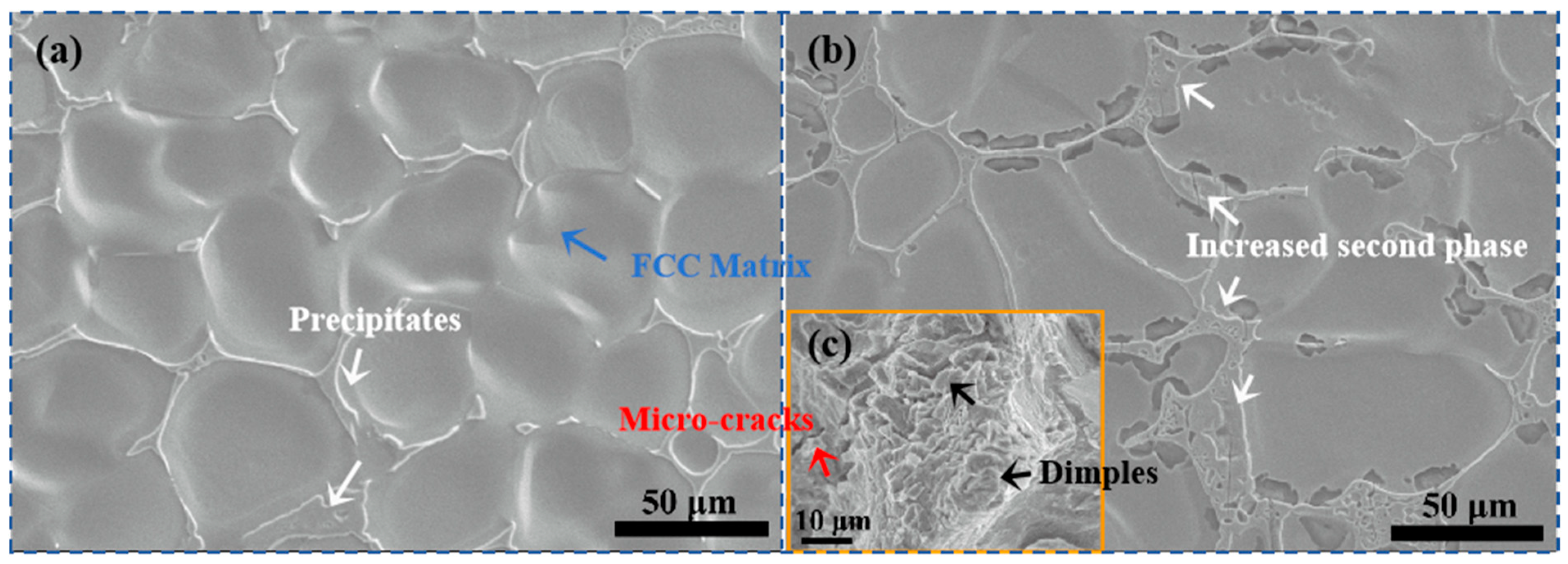
3.2. Microstructure Evolution

Figure 3a presents the XRD patterns of the as-cast CoCr0.4NiSi0.3 MEA after tensile testing at room temperature, −75 °C, and −150 °C. After tensile testing at room temperature, minor amounts of secondary phases, including L12, hexagonal close-packed (HCP), and tetragonal structures, were detected. Upon tensile testing at −75 °C and −150 °C, the orthorhombic phase emerged, indicating that the MEA underwent a metastable phase transition under cryogenic temperatures combined with mechanical stress. After tensile deformation at −150 °C, the diffraction intensity of the characteristic peaks were significantly reduced. This reduction can be attributed to severe lattice distortion caused by cryogenic deformation, leading to increased X-ray scattering from roughened Bragg planes, thereby weakening the diffraction signal and diminishing the peak intensity. Figure 3b displays the average grain sizes of the alloy at room temperature, −75 °C, and −150 °C, as determined by EBSD analysis. The results indicate that, although the average grain size decreases with a reduction in deformation cryogenic temperature, it is still larger than that observed following quasi-static tensile testing at room temperature.
Figure 4a and Figure 4b respectively illustrate the microstructure of the CoCr0.4NiSi0.3 MEA before and after tensile testing at room temperature, while Figure 4c shows the fracture morphology after tensile testing. According to previous studies [26] and Figure 4a,b, the second phase predominantly resides along the grain boundaries in as-cast MEA. Following tensile deformation, the grains exhibit pronounced elongation and distortion, leading to an increased concentration of the second phase at these boundaries. The central region of the fracture surface displays dimples, whereas the peripheral areas feature tearing ridges accompanied by shallow cracks, which can be attributed to the presence of second-phase inclusions.
Figure 5 presents the high-resolution transmission electron microscopy (HR-TEM) image and corresponding crystal structure analysis of the CoCr0.4NiSi0.3 MEA after tensile testing at room temperature, observed along the [0–11] zone axis of the FCC matrix. Figure 5b displays the HR-TEM image of region A in Figure 5a, while Figure 5c shows the fast Fourier transform (FFT) pattern of the same region. Figure 5d illustrates the inverse fast Fourier transform (IFFT) of region A in Figure 5a. Electron diffraction analysis following tensile deformation at room temperature reveals that a strong L12 phase diffraction spot coexists with the FCC matrix in the selected area. According to the diffraction peaks of the second phase indexed in Figure 3a, a minor presence of tetragonal and HCP secondary phases is also detected after tensile testing at room temperature. As shown in Figure 5d, the interplanar spacing of the HCP phase is 1.96 Å, whereas that of the FCC matrix is 2.046 Å. The lattice mismatch between the secondary phase and the matrix is calculated to be 4.4%, which is relatively small. Although this level of lattice distortion does not compromise the ductility of the MEA, it can elevate the Gibbs free energy and impede dislocation slip, thereby enhancing the strength of the MEA.
Figure 6 illustrates the fracture morphology of the CoCr0.4NiSi0.3 MEA subjected to quasi-static tensile testing at −75 °C and −150 °C. The MEA displays ductile fracture characteristics under cryogenic conditions. Notably, the depth of dimples decreases as the deformation temperature drops. Furthermore, the quantity of micro-pores near the tearing edge, which originate from the second phase, diminishes as the deformation temperature decreases. This observation indicates that the deformation temperature has a substantial impact on both the composition and distribution of the precipitated phase.
Figure 7a,b display the microstructure and bright-field transmission electron microscopy (BF-TEM) images of the CoCr0.4NiSi0.3 MEA after tensile deformation at −75 °C, while Figure 7c,d illustrate the corresponding features of the alloy deformed at −150 °C. A comparative analysis of Figure 7a,c reveals that as the tensile deformation temperature decreases, the size of the secondary phase diminishes, its distribution shifts from primarily along grain boundaries to within the grains, and distinct cross-slip bands become evident within the grains. As illustrated in Figure 7b,d, with the reduction in deformation temperature, the volume fraction of dislocations decreases while the width and density of SFs increase. The number of Lomer–Cottrell locks (LC-locks) also increases, with LC-locks being more densely distributed in regions where SFs are abundant. This phenomenon contributes to strengthening and enhances the cryogenic strength of the alloy. Consequently, the traditional trade-off between strength and plasticity is mitigated, suggesting an unconventional deformation mechanism at low temperatures.
Figure 8a,b illustrate the superposition of the inverse pole figure (IPF) and GB maps for CoCr0.4NiSi0.3 MEA after tensile testing at −75 °C and −150 °C, respectively. At −75 °C, the grains exhibit significant elongation, while at −150 °C, grain fragmentation is more pronounced. The proportion of low-angle grain boundaries (LAGBs) decreased from 84.2% to 78.7%, suggesting a slight reduction in dislocation density with decreasing deformation temperature. Meanwhile, the volume fraction of Σ3 GBs increased from 6.78% to 7.40%, indicating enhanced multi-system slip due to the coordinated deformation of initial twins. However, no distinct texture formation was observed, and the grain orientation remained anisotropic. The increase in SFs and their subsequent transformation into twins lead to a higher twin volume fraction. Concurrently, the volume fraction of sub-GBs decreases, which facilitates the stress release and diminishes the driving force for phase transitions. Phase transitions predominantly occur within the twinned regions, with the L12 phase transition being the most prominent at −75 °C. Tensile testing at −150 °C results in an increased density of SFs in two directions, and the bi-directional TWIP effect promotes deformation while enhancing both strength and ductility.

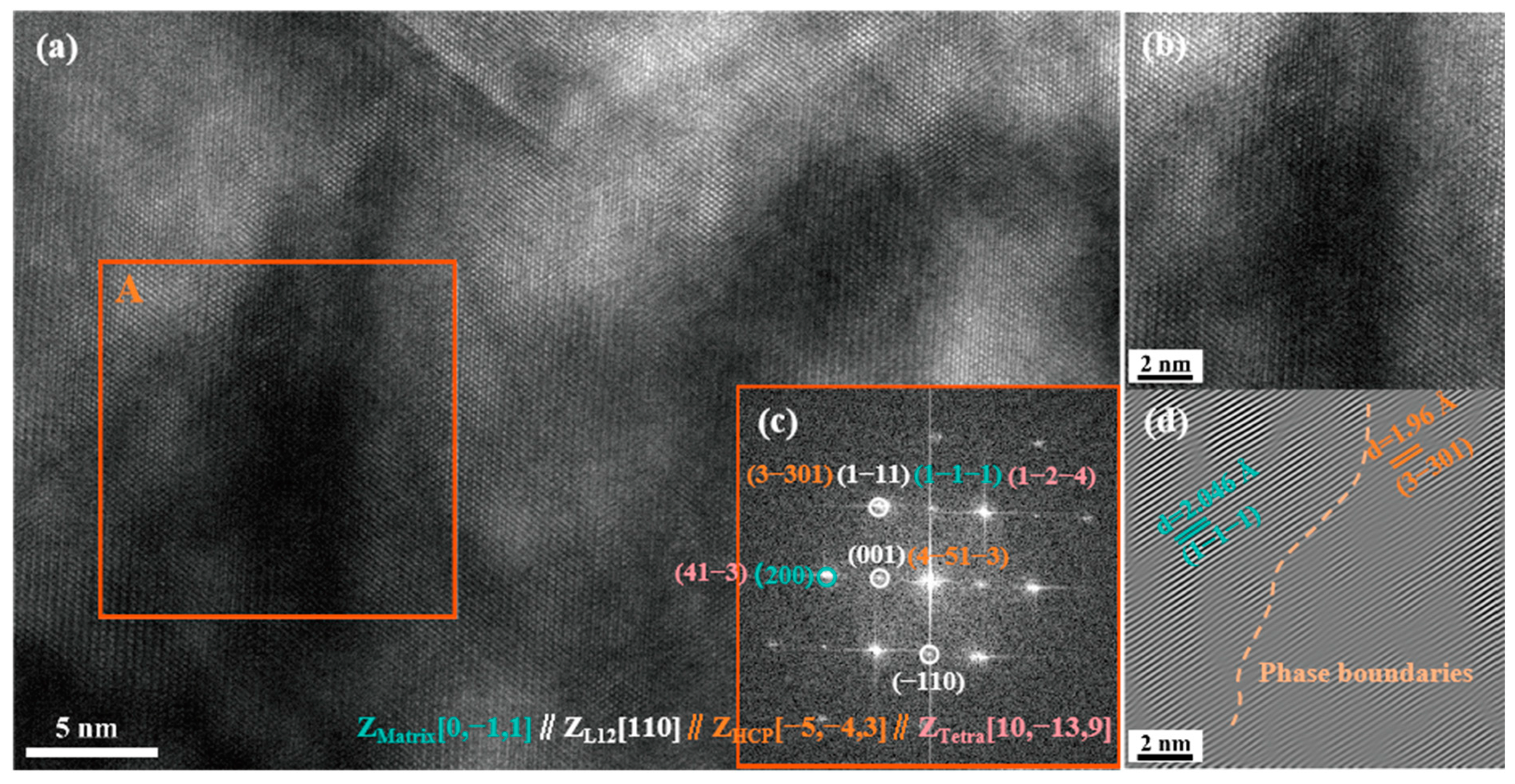
3.3. Mechanism of Cryogenic Tensile Deformation

Figure 9 illustrates the interaction morphology between the L12 phase and SFs in the CoCr0.4NiSi0.3 MEA after tensile testing at −75 °C. As depicted in Figure 9a, dense SFs are observed in the CoCr0.4NiSi0.3 MEA following tensile deformation at −75 °C, with the lamellae spacing of smaller SFs measuring approximately 5.15 nm. The width of the antiphase boundaries (APBs) within the L12 phase is 3.03 nm, resulting from a/6<112> partial dislocations sweeping SFs via decomposing perfect dislocations when shearing the L12 phase [27,28]. It suggests that the SFE of the MEA is relatively low at this tested temperature, thereby permitting the formation of wider APBs. Figure 9b presents the FFT of the region shown in Figure 9a, while Figure 9c displays the FFT of the L12 phase from Figure 9b. These results indicate that spheroidal L12 particles with a diameter of ~ 10 nm persist even when numerous deformation-induced SFs intersect the L12 phase after deformation at −75 °C. The L12 phase transition at cryogenic temperatures has not been previously documented in metals and alloys. The L12 phase observed after tensile testing at −75 °C is likely due to an ordering transition from the FCC phase at this temperature. This transition is typically characterized by the formation of APBs [29]. The observations from Figure 9 indicate that the presence of dispersed coherent nano-strengthening L12 particles at −75 °C promotes the decomposition of perfect dislocations and the formation of APBs. This significantly enhances the strength of the MEA at cryogenic temperatures while achieving a well-balanced combination of strength and ductility.
Figure 10a presents the HR-TEM image of the CoCr0.4NiSi0.3 MEA after tensile deformation at −75 °C. Figure 10b displays the FFT pattern of region A in Figure 10a. Figure 10c provides an enlarged HR-TEM image of region A from Figure 10a, while Figure 10d shows the IFFT image of the same region. Clear SFs are evident in Figure 10a,c. Figure 10b exhibits clear {111} crystal plane diffraction fringes corresponding to these SFs, along with faint diffraction spots from the coexisting L12, tetragonal, and orthorhombic phases within the matrix. Observations along the [0–11] zone axis of the FCC matrix, in comparison with Figure 10c,d, indicate that there is no significant difference in the { 1 1 ¯ 1 ¯ } interplanar spacing between regions with and without SFs.
Figure 11 presents the HR-TEM image of a distinct area of the CoCr0.4NiSi0.3 MEA after tensile deformation at −75 °C. Figure 11(a1) shows the FFT pattern corresponding to region A in Figure 11, while Figure 11(a2) displays the HR-TEM image of region A. Figure 11(a3) illustrates the IFFT image of the (002) crystal plane within region A. Region A demonstrates a coherent interface between the FCC matrix, L12 phase, and tetragonal phase. SFs and LC-locks are clearly visible in the HR-TEM images. The interaction between planar defects within the nanolayer region and the L12 phase results in residual SFs. In Figure 11(a2), within the region outlined by the light blue line, a slight lattice mismatch is observed adjacent to the coherent phase interface, as evidenced by the corresponding IFFT image in Figure 11(a3). The tetragonal phase develops at this deformation temperature, suggesting that the synergistic effects of cryogenic conditions and applied stress, particularly the significant reduction in SFE due to the cryogenic environment, enhance the degree of chemical ordering. As a result, the FCC-L12 phase experiences Jahn–Teller distortion, leading to the formation of orthorhombic martensite [30]. The occurrence of Jahn–Teller distortion is associated with the first-order phase transition in Co-rich compounds [31,32,33]. Furthermore, since the primary metallic component of this alloy belongs to the 3d transition metal group and Si acts as a semiconductor element, the electron distribution in this MEA tends to exhibit degenerate states. Consequently, this type of phase transition is more likely to occur. This cryogenic-induced phase transition in this 3d transition metal MEA, observed over an extensive range of cryogenic temperatures, consistently exhibits a tetragonal structure as a metastable intermediate state during the transformation from L12 to orthorhombic martensite [30], as depicted in Figure 11(a2). The figure clearly illustrates the coherent existence of the tetragonal phase with the L12 phase.
Figure 12 presents HR-TEM images and electron diffraction patterns of the CoCr0.4NiSi0.3 MEA after tensile deformation at −150 °C. Figure 12(a1,b1,c1) correspond to the electron diffraction patterns associated with Figure 12a, Figure 12b, and Figure 12c, respectively. The images reveal that after tensile deformation at −150 °C, nanotwins, SFs, HCP, and LPSO structures coexist within the FCC matrix of the MEA. Notably, Figure 12c illustrates that densely arranged SFs are in close proximity to the LPSO structure and nanotwin regions, forming a more compact network of LC-locks under tensile conditions at this cryogenic temperature. According to the Zener–Hollomon equation, Z = ε ˙ exp ( Q / R T ) , reducing the deformation temperature is effectively equivalent to increasing the strain rate. Based on the dynamic mechanical properties of this MEA [26], it can be inferred that dislocation activity is significantly inhibited at cryogenic temperatures due to the phase transitions from SFs → HCP and deformation twins (DTs) → HCP in the microstructure, as well as their superior dynamic mechanical properties. The formation of DTs is triggered by local stress concentration, and the DTs → HCP phase transition occurs under higher critical tensile stress. Further characterization of this region is provided in Figure 13 via HR-TEM.
Figure 13 shows an HR-TEM image of the CoCr0.4NiSi0.3 MEA after tensile deformation at −150 °C. Figure 13(a1,b1,c1) are enlarged HR-TEM images of regions A, B, and C in Figure 13, respectively. Figure 13(a2,a3) display the IFFT and FFT images of region A1, respectively. Similarly, Figure 13(b2,b3) show the IFFT and FFT images of region B1, while Figure 13(c1,c2) present the IFFT and FFT images of region C. All observations were conducted along the [−1−10] zone axis of the FCC matrix. The interplanar spacing of the { 1 ¯ 11 } planes was measured in regions A, B, and C. Region A, characterized by dense SFs and LPSO structure, exhibited a slightly larger interplanar spacing compared to region B but slightly smaller than that in region C, which features a coherent tetragonal structure with nanotwins in the SF regions. The diffraction spot intensity from the tetragonal phase in region C was more pronounced compared to that observed during tensile deformation at −75 °C. These results indicate that cryogenic temperature tensile stress induces more extensive phase transitions. The L12 phase was not observed at the tensile deformation temperature of −150 °C. The TEM images in Figure 7 and the IPF maps in Figure 8 reveal that the MEA exhibits a higher density of SFs at −150 °C compared to −75 °C during tensile deformation, accompanied by the occurrence of DTs. This phenomenon can be attributed to the low SFE, which leads to the generation of a significant number of Shockley partial dislocations [34]. The twin formation mechanism at this temperature is primarily driven by boundary emission of partial dislocations [35,36,37,38]. Additionally, TEM morphologies and LAGB ratio analysis reveal a significant reduction in dislocation density following tensile testing at −150 °C. The LPSO structure appeared in the SF region after cryogenic tensile testing, indicating that cryogenic temperatures enabled a further reduction in SFE. This resulted in more perfect dislocation decomposition, generating a significant number of Shockley partial dislocations and promoting planar slip, thereby enhancing the SFs → LPSO phase transition under tensile stress. The Mg-Gd-Y-Zn-Zr alloy [37] undergoes an SFs → LPSO phase transition when aged at 200 °C and 250 °C. Similarly, Mg-10Gd−3Y-1.2Zn-0.4Zr [38] SFs and certain eutectic compounds gradually dissolve into the matrix to form LPSO structures following annealing at 525 °C. However, no reports have documented an SFs → LPSO phase transition during cryogenic temperature conditions after tensile testing. Furthermore, the SFs → LPSO phase transition has been observed in the CoCr0.4NiSi0.3 MEA during both hot compression [20] and tensile testing [21] at elevated temperatures. These observations indicate that under tensile stress conditions, the LPSO phase can form extensively across a range of deformation temperatures.
This phenomenon is attributed to the low intrinsic SFE of the MEA and the evolution pathways of the deformed a/6<112> Shockley partial dislocations at different temperatures. Therefore, in this MEA, the metastable phase transition process at varying temperatures consistently results in perfect dislocation decomposition, leading to the formation of a/6<112> SFs. The evolution of these SFs is critical to the phase transition process [21]. With the decrease in tensile deformation temperature, the SFE diminishes, thereby increasing the propensity for SFs. As flow stress increases, DTs are activated, leading to the TWIP effect and displacement-induced phase transformation. This results in the formation of local chemical ordering structures and nanoscale precipitates, ultimately contributing to the TRIP effect. When the deformation temperature decreases to −150 °C, the density of SFs rises, and the interaction between nanoscale planar defects and precipitates enhances strain hardening. The elevated flow stress enables the MEA to reach the critical threshold for DT activation at cryogenic temperatures, initiating twinning. Consequently, as the deformation temperature decreases, both the strength and ductility of the MEA improve, demonstrating the superior comprehensive mechanical properties of the CoCr0.4NiSi0.3 MEA in its as-cast state at cryogenic temperatures.

4. Conclusions

In this study, the quasi-static mechanical properties of CoCr0.4NiSi0.3 MEA were examined at room temperature, −75 °C, and −150 °C. Through microstructure characterization of the deformed samples, the following conclusions were drawn:
(1) The as-cast MEA exhibits superior cryogenic mechanical properties, characterized by a significant increase in strength as temperatures decrease. Specifically, both the YS and UTS of the as-cast MEA increase with decreasing temperature. At −150 °C, the YS and UTS reach 617.5 MPa and 1055.0 MPa, respectively, while the EF remains consistent at 21.0% for both −150 °C and −75 °C.
(2) The L12 phase and LPSO structures emerge after cryogenic tensile testing, phenomena that have not been previously reported in metals and alloys. After deformation at various cryogenic temperatures, the matrix exhibits dispersed nano-sized tetragonal and orthorhombic phases, along with enhanced chemical ordering resulting from Jahn–Teller distortion at lower cryogenic temperatures. At −75 °C, the matrix contains L12 phases with diameters of approximately 10 nm, along with APBs about 3 nm thick within the L12 phase. At −150 °C, lamellar LPSO structures and nano-scale DTs appear. The dispersion of coherent nanoprecipitates and DTs in the matrix after deformation is a critical factor contributing to the excellent balance of strength and plasticity at cryogenic temperatures for the as-cast MEA.
(3) The metastable phase evolution path of the MEA at cryogenic temperatures is closely associated with the decomposition of perfect dislocations into a/6<112> Shockley partial dislocations and their subsequent evolution at reduced temperatures. Following deformation at −75 °C, these a/6<112> Shockley partial dislocations interact with L12 precipitates, leading to the formation of high-energy APB defects. At −150 °C, the a/6<112> Shockley partial dislocations facilitate the formation of SFs, which subsequently evolve into nanoscaled structures via the phase transition pathways of SFs → nanotwins and SFs → LPSO structures. The development of nanotwins promotes grain refinement, thereby enhancing both the strength and ductility of the MEA.

Author Contributions

Conceptualization, L.Z. (Li Zhang); methodology, L.Z. (Li Zhang); software, L.Z. (Li Zhang); validation, L.Z. (Li Zhang); formal analysis, L.Z. (Li Zhang); investigation, X.C. and L.Z. (Lingwei Zhang); resources, L.Z. (Li Zhang); data curation, X.C., and L.Z. (Lingwei Zhang); writing—original draft preparation, L.Z. (Li Zhang); writing—review and editing, L.Z. (Li Zhang); visualization, L.Z. (Li Zhang); supervision, L.Z. (Li Zhang); project administration, L.Z. (Li Zhang); funding acquisition, L.Z. (Li Zhang) All authors have read and agreed to the published version of the manuscript.

Funding

This work was funded by the General Programs of Education Department of Liaoning Province (Grant No. LJKMZ20220592, 2022).

Data Availability Statement

The data presented in this study are available on request from the corresponding author. The data are not publicly available due to privacy.

Conflicts of Interest

The authors declare no conflict of interest.

References

  1. Liu, J.; Guo, X.; Lin, Q.; He, Z.; An, X.; Li, L.; Liaw, P.K.; Liao, X.; Yu, L.; Lin, J.; et al. Excellent ductility and serration feature of metastable CoCrFeNi high-entropy alloy at extremely low temperatures. Sci. China Mater. 2018, 62, 853–863. [Google Scholar] [CrossRef]
  2. Liu, L.-X.; Pan, J.; Zhang, P.-C.; Guo, R.; Xu, J.-Y.; Liu, L. Tensile and impact behavior of 3D-printed (FeCoNi)86Al7Ti7 high entropy alloy at ambient and cryogenic temperatures. Mater. Des. 2024, 242, 113020. [Google Scholar] [CrossRef]
  3. Zhang, Y.; Zuo, T.T.; Tang, Z.; Gao, M.C.; Dahmen, K.A.; Liaw, P.K.; Lu, Z.P. Microstructures and properties of high-entropy alloys. Prog. Mater. Sci. 2014, 61, 1–93. [Google Scholar] [CrossRef]
  4. Liu, W.H.; Wu, Y.; He, J.Y.; Nieh, T.G.; Lu, Z.P. Grain growth and the hall–petch relationship in a high-entropy FeCrNiCoMn alloy. Scr. Mater. 2013, 68, 526–529. [Google Scholar] [CrossRef]
  5. Gludovatz, B.; Hohenwarter, A.; Catoor, D.; Chang, E.H.; George, E.P.; Ritchie, R.O. A fracture-resistant high-entropy alloy for cryogenic applications. Science 2014, 345, 1153–1158. [Google Scholar] [CrossRef]
  6. Otto, F.; Dlouhý, A.; Somsen, C.; Bei, H.; Eggeler, G.; George, E.P. The influences of temperature and microstructure on the tensile properties of a CoCrFeMnNi high-entropy alloy. Acta Mater. 2013, 61, 5743–5755. [Google Scholar] [CrossRef]
  7. Laplanche, G.; Kostka, A.; Horst, O.M.; Eggeler, G.; George, E.P. Microstructure evolution and critical stress for twinning in the CrMnFeCoNi high-entropy alloy. Acta Mater. 2016, 118, 152–163. [Google Scholar] [CrossRef]
  8. Jo, Y.H.; Jung, S.; Choi, W.M.; Sohn, S.S.; Kim, H.S.; Lee, B.J.; Kim, N.J.; Lee, S. Cryogenic strength improvement by utilizing room-temperature deformation twinning in a partially recrystallized vcrmnfeconi high-entropy alloy. Nat. Commun. 2017, 8, 15719. [Google Scholar] [CrossRef]
  9. Zhang, Z.; Sheng, H.; Wang, Z.; Gludovatz, B.; Zhang, Z.; George, E.P.; Yu, Q.; Mao, S.X.; Ritchie, R.O. Dislocation mechanisms and 3D twin architectures generate exceptional strength-ductility-toughness combination in CrCoNi medium-entropy alloy. Nat. Commun. 2017, 8, 14390. [Google Scholar] [CrossRef] [PubMed]
  10. Magalhães, D.C.; Kliauga, A.M.; Ferrante, M.; Sordi, V.L. Plastic deformation of FCC alloys at cryogenic temperature: The effect of stacking-fault energy on microstructure and tensile behaviour. J. Mater. Sci. 2017, 52, 7466–7478. [Google Scholar] [CrossRef]
  11. Huang, S.; Li, W.; Lu, S.; Tian, F.; Shen, J.; Holmström, E.; Vitos, L. Temperature dependent stacking fault energy of FeCrCoNiMn high entropy alloy. Scr. Mater. 2015, 108, 44–47. [Google Scholar] [CrossRef]
  12. Laplanche, G.; Kostka, A.; Reinhart, C.; Hunfeld, J.; Eggeler, G.; George, E.P. Reasons for the superior mechanical properties of medium-entropy CrCoNi compared to high-entropy CrMnFeCoNi. Acta Mater. 2017, 128, 292–303. [Google Scholar] [CrossRef]
  13. Gludovatz, B.; Hohenwarter, A.; Thurston, K.V.; Bei, H.; Wu, Z.; George, E.P.; Ritchie, R.O. Exceptional damage-tolerance of a medium-entropy alloy CrCoNi at cryogenic temperatures. Nat. Commun. 2016, 7, 10602. [Google Scholar] [CrossRef] [PubMed]
  14. Chang, H.; Zhang, T.W.; Ma, S.G.; Zhao, D.; Xiong, R.L.; Wang, T.; Li, Z.Q.; Wang, Z.H. Novel si-added CrCoNi medium entropy alloys achieving the breakthrough of strength-ductility trade-off. Mater. Des. 2021, 197, 109202. [Google Scholar] [CrossRef]
  15. Tai, C.L.; You, J.D.; Chen, J.J.; Liang, S.C.; Chung, T.F.; Yang, Y.L.; Ii, S.; Ohmura, T.; Zheng, X.; Chen, C.Y.; et al. In-situ transmission electron microscopy investigation of the deformation mechanism in CoCrNi and cocrnisi0.3 nanopillars. Scr. Mater. 2025, 255, 116405. [Google Scholar] [CrossRef]
  16. Guo, S.; Ng, C.; Lu, J.; Liu, C.T. Effect of valence electron concentration on stability of FCC or BCC phase in high entropy alloys. J. Appl. Phys. 2011, 109, 103505. [Google Scholar] [CrossRef]
  17. Zhang, D.D.; Wang, H.; Zhang, J.Y.; Xue, H.; Liu, G.; Sun, J. Achieving excellent strength-ductility synergy in twinned NiCoCr medium-entropy alloy via Al/Ta co-doping. J. Mater. Sci. Technol. 2021, 87, 184–195. [Google Scholar] [CrossRef]
  18. Wang, L.X.; Xiang, S.; Tan, Y.B.; Shi, W.; Liu, F.; Cai, Y.Q.; Ji, X.M. The Design of Appropriate Si Content Overcomes the Strength-Ductility Trade-off in Dual-Phase High Entropy Alloy. J. Alloys Compd. 2024, 1004, 175738. [Google Scholar] [CrossRef]
  19. Lopes, J.G.; Shen, J.; Maawad, E.; Agrawal, P.; Schell, N.; Mishra, R.S.; Oliveira, J.P. Time-resolved evolution of the deformation mechanisms in a TRIP/TWIP Fe50Mn30Co10Cr10 high entropy during tensile loading probed with synchrotron X-ray diffraction. Int. J. Plast. 2024, 179, 104048. [Google Scholar] [CrossRef]
  20. Zhang, L.; Zhao, H.; Chen, L.; Li, F.; Zhang, W.; Zhou, G.; Zhang, H.; Geng, N. Investigation of the Hot Deformation Behavior and Mechanism of a Medium-Entropy CoCr0.4NiSi0.3 Alloy. Crystals 2024, 14, 3. [Google Scholar] [CrossRef]
  21. Zhang, L.; Chen, L.; Zhang, W.; Zhao, H.; Li, F. Thermomechanically induced phase separation at elevated temperatures in a CoCr0.4NiSi0.3 medium-entropy alloy. J. Mater. Res. Technol. 2025, 34, 1908–1920. [Google Scholar] [CrossRef]
  22. Gao, X.; Liu, J.; Fu, W.; Huang, Y.; Ning, Z.; Zhang, Z.; Sun, J.; Chen, W. Strong and ductile CoCrFeNi high-entropy alloy microfibers at ambient and cryogenic temperatures. Mater. Des. 2023, 233, 112250. [Google Scholar] [CrossRef]
  23. Li, L.; Song, K.; Gao, Q.; Zhou, C.; Liu, X.; Wang, Y.; Bai, X.; Cao, C. Enhancing strength-ductility synergy of CoCrNi-based medium-entropy alloy through coherent L12 Nanoprecipitates and grain boundary precipitates. Acta Metall. Sin. (Engl. Lett.) 2023, 37, 78–88. [Google Scholar] [CrossRef]
  24. Gao, L.; Wu, Y.; An, N.; Chen, J.; Liu, X.; Bai, R.; Hui, X. Nanoscale L12 phase precipitation induced superb ambient and high temperature mechanical properties in Ni-Co-Cr-Al System high-entropy superalloys. Mater. Sci. Eng. A 2024, 898, 145995. [Google Scholar] [CrossRef]
  25. Karpstein, N.; Lenz, M.; Bezold, A.; Wu, M.; Neumeier, S.; Spiecker, E. Reliable identification of the complex or superlattice nature of intrinsic and extrinsic stacking faults in the L12 phase by high-resolution imaging. Acta Mater. 2023, 260, 119284. [Google Scholar] [CrossRef]
  26. Zhang, L.; Zhang, W.; Chen, L.; Li, F.; Zhao, H.; Wang, X.; Zhou, G. Microstructure and texture evolution of a dynamic compressed medium-entropy CoCr0.4NiSi0.3 alloy. Crystals 2023, 13, 1390. [Google Scholar] [CrossRef]
  27. Yuan, J.L.; Wang, Z.; Jin, X.; Han, P.D.; Qiao, J.W. L12-strengthened heterostructure high-entropy alloys with ultra-high strength over a wide temperature range. Mater. Sci. Eng. A 2022, 853, 143712. [Google Scholar] [CrossRef]
  28. Rae, C.M.F.; Reed, R.C. Primary creep in Single Crystal Superalloys: Origins, mechanisms and effects. Acta Mater. 2007, 55, 1067–1081. [Google Scholar] [CrossRef]
  29. Wang, S.; Chen, S.; Jia, Y.; Hu, Z.; Huang, H.; Yang, Z.; Dong, A.; Zhu, G.; Wang, D.; Shu, D.; et al. FCC-L12 ordering transformation in equimolar feconiv multi-principal element alloy. Mater. Des. 2019, 168, 107648. [Google Scholar] [CrossRef]
  30. Yamamoto, M.; Fukuda, T.; Kakeshita, T.; Takahashi, K. Orthorhombic martensite formed in L12-Type Fe3Pt Invar alloy. J. Alloys Compd. 2013, 577, S503–S506. [Google Scholar] [CrossRef]
  31. Eberhart, M.E.; O’Handley, R.C.; Johnson, K.H. Molecular-orbital models of structural phase transformations in crystalline and amorphous cobalt alloys. Phys. Rev. B Condens. Matter Mater. Phys. 1984, 29, 1097–1100. [Google Scholar] [CrossRef]
  32. Hope, D.A.O.; Cheetham, A.K. A low-temperature powder neutron diffraction study of the antiferromagnetic phase of MnxCo1−XO. J. Solid State Chem. 1988, 72, 42–51. [Google Scholar] [CrossRef]
  33. Jiang, F.; Chen, S.; Zhang, H.; Wang, X.; Di, Y.; Liu, E.; Li, T.; Deng, L.; Zhu, X.; Huang, D. Correction to: First-principles study on the jahn-teller distortion in trigonal bipyramidal coordinated LiFe1−xMxBO3 (M=Mn, Co, and Ni) compounds. J. Solid State Electrochem. 2020, 25, 637. [Google Scholar] [CrossRef]
  34. Molnár, D.; Engberg, G.; Li, W.; Vitos, L. Deformation properties of austenitic stainless steels with different stacking fault energies. Mater. Sci. Forum 2018, 941, 190–197. [Google Scholar] [CrossRef]
  35. Mahato, B.; Shee, S.K.; Sahu, T.; Ghosh Chowdhury, S.; Sahu, P.; Porter, D.A.; Karjalainen, L.P. An effective stacking fault energy viewpoint on the formation of extended defects and their contribution to strain hardening in a Fe-Mn-Si-Al twinning-induced plasticity steel. Acta Mater. 2015, 86, 69–79. [Google Scholar] [CrossRef]
  36. Van Swygenhoven, H.; Derlet, P.M.; Hasnaoui, A. Atomic mechanism for dislocation emission from nanosized grain boundaries. Phys. Rev. B 2002, 66, 024101. [Google Scholar] [CrossRef]
  37. Meng, M.; Zhang, H.; Gao, Z.; Lei, G.; Yu, J. Effect of aging treatment on the precipitation transformation and age hardening of Mg-Gd-Y-Zn-Zr alloy. J. Magnes. Alloys 2023, 11, 4628–4643. [Google Scholar] [CrossRef]
  38. Li, D.; Zeng, X.; Dong, J.; Zhai, C. Influence of heat treatment on microstructure and mechanical properties of Mg-10Gd-3Y-1.2Zn-0.4Zr alloy. Trans. Nonferrous Met. Soc. China 2008, 18, s117–s121. [Google Scholar] [CrossRef]
Figure 1. The (a) engineering stress-strain and (b) EF curves of the CoCr0.4NiSi0.3 MEA at room and cryogenic temperatures.
Crystals 15 00170 g001
Figure 2. The (a) YS and (b) UTS of the CoCr0.4NiSi0.3 MEA tensile tested at room and cryogenic temperatures.
Crystals 15 00170 g002
Figure 3. The (a) XRD pattern and (b) average grain size diagram of the CoCr0.4NiSi0.3 MEA tensile tested at room and cryogenic temperatures.
Crystals 15 00170 g003
Figure 4. Morphological images of the CoCr0.4NiSi0.3 MEA before and after tensile testing at room temperature. The morphological images of the CoCr0.4NiSi0.3 MEA (a) in its as-cast state, (b) after tensile testing, and (c) showing its fracture surfaces.
Crystals 15 00170 g004
Figure 5. The HR-TEM images of (a) the CoCr0.4NiSi0.3 MEA tensile tested at room temperature and (b) the region A in Figure 5a. The (c) FFT pattern and (d) IFFT of the region A in Figure 5a.
Crystals 15 00170 g005
Figure 6. Fracture morphologies of the CoCr0.4NiSi0.3 MEA following tensile testing at (a) −75 °C and (b) −150 °C.
Crystals 15 00170 g006
Figure 7. The (a) SEM and (b) BF-TEM images of the CoCr0.4NiSi0.3 MEA following tensile testing at −75 °C. The (c) SEM and (d) BF-TEM images of the CoCr0.4NiSi0.3 MEA following tensile testing at −150 °C.
Crystals 15 00170 g007
Figure 8. GBs superimposed on IPF images from specimens subjected to cryogenic tensile testing at (a) −75 °C and (b) −150 °C.
Crystals 15 00170 g008
Figure 9. (a) Morphology of the interaction between L12 and SFs in a CoCr0.4NiSi0.3 MEA after tensile testing at −75 °C; (b) the FFT pattern corresponding to Figure 9a; (c) the FFT diagram illustrating the L12 phase from Figure 9b.
Crystals 15 00170 g009
Figure 10. (a) HR-TEM image of the CoCr0.4NiSi0.3 MEA after tensile testing at −75 °C. (b) The FFT pattern of region A in Figure 10a. The (c) enlarged HR-TEM image and (d) IFFT image of region A in Figure 10a.
Crystals 15 00170 g010
Figure 11. HR-TEM image of the CoCr0.4NiSi0.3 MEA after tensile testing at −75 °C. The (a1) FFT image, (a2) enlarged HR-TEM image, and (a3) IFFT diagram of region A in Figure 11.
Crystals 15 00170 g011
Figure 12. (ac) The HR-TEM images of the CoCr0.4NiSi0.3 MEA tensile tested at −150 °C. (a1c1) The electron diffraction patterns corresponding to (ac).
Crystals 15 00170 g012
Figure 13. The HR-TEM image of the CoCr0.4NiSi0.3 MEA after tensile testing at −150 °C. The enlarged HR-TEM images of (a1) region A and (b1) region B in Figure 13. The corresponding IFFT images for (a2) region A and (b2) region B, as well as the FFT images for (a3) region A and (b3) region B. The (c1) IFFT image and (c2) FFT image of region C in Figure 13.
Crystals 15 00170 g013
Table 1. Nominal composition of the as-cast CoCr0.4NiSi0.3 MEA (at.%).
CoCrNiSi
40.1314.1639.975.74
Table 2. Strengths and elongation of the as-cast CoCr0.4NiSi0.3 MEA at room and cryogenic temperatures (MPa).
Test TemperatureYSUTSEF
RT437.0 ± 4.2825.0 ± 17.013.5% ± 4.9%
−75 °C550.0 ± 4.2993.5 ± 20.521.5% ± 2.8%
−150 °C617.5 ± 12.01055.0 ± 60.821.0% ± 4.9%
Disclaimer/Publisher’s Note: The statements, opinions and data contained in all publications are solely those of the individual author(s) and contributor(s) and not of MDPI and/or the editor(s). MDPI and/or the editor(s) disclaim responsibility for any injury to people or property resulting from any ideas, methods, instructions or products referred to in the content.

