Abstract
Due to the severe corrosion environment, corrosion problems caused by sulfur deposition are one important reason for the failure of composite pipes in the long-term service process when Incoloy825/X65 bimetallic composite pipes are used in high-sulfur oil and gas transportation. In this paper, an Incoloy825/X65 bimetallic composite pipe was subjected to an immersion corrosion test in suspended sulfur solution to observe the corrosion morphology and characterize the corrosion products using a SEM, EDS, and XRD. The adsorption behavior of the Incoloy825 alloy in terms of sulfur elements was investigated. The results show that the heat-affected zone (HAZ) of the welding joint is the preferred region for pitting corrosion. The film of corrosion product on the Incoloy825 was mainly composed of NiS, FeS, and Cr2S3, and its thickness was 7–13 μm. With prolongation of the immersion time, the pitting resistance of the surface product film of nickel-based alloys is weakened and then enhanced, and the corrosion product film can act as a barrier to anion transfer and inhibit the occurrence of pitting.
1. Introduction
With the constant rise in the energy demands all over the world, the development of oil–gas resources is transferring to harsh environmental conditions, such as high-temperature and high-pressure areas. These areas and the crude oil stored in these areas usually have a high content of CO2, Cl−, H2S, and so on, which have strong corrosive effects on transportation pipelines [1,2,3]. Bimetal composite pipes combine the strength of carbon steels and the corrosion resistance of stainless steel or alloys in their performance, thus being widely used in the field of the transport of oil, gas, and refinery products [4,5]. Bimetal composite pipes are composed of an outer thick layer of carbon steel (such as 20, L245, X65, X70, X80 steels, etc.) and an inner thin layer of corrosion-resistant alloys (such as austenitic stainless steel or nickel-based alloys). Due to the excellent H2S corrosion resistance of nickel-based alloys, they are more and more widely used in high-sulfur gas fields and extraction, transportation, and storage [6]. Although the failure of gathering pipelines is largely reduced by using bimetal composite pipes, there are also individual failure cases, most of which are caused by corrosion failure of the welding joint areas [7]. The pipe corrosion in high-sulfur oil and gas fields is mainly H2S corrosion, CO2 corrosion, H2S/CO2 coexistence system corrosion, and elemental sulfur corrosion. At present, there are more studies on H2S and CO2 corrosion but fewer studies on sulfur corrosion, so it is of significant reference value to investigate the corrosion behavior of welded joints in bimetallic composite pipes for their application in sulfur-rich environments.
In this study, a bimetallic composite pipe butt joint was prepared through surface welding. The corrosion behavior of an Incoloy825/X65 bimetallic composite pipe welded joint in suspended sulfur solution was investigated through an immersion test. The corrosion morphology, element distribution, and passivation behavior of the welded joint were analyzed using an optical microscope (OM, Zeiss, Axio Scope A1, Carl Zeiss AG, Baden-Württemberg, Germany), a scanning electron microscope (SEM, JSM-7200F, JEOL Ltd., Tokyo, Japan), and electron-dispersive spectroscopy (EDS, Oxford Instruments, Oxford, UK). The composition of the corrosion products was identified through X-ray diffraction (XRD, X’Pert PRO, PANalytical B.V., Almelo, The Netherlands) using Cu Kα radiation at a scanning speed of 4°/min. The passive film rupture and the development of pitting were discussed. This study aimed to provide an experimental and theoretical basis for the application of Incoloy825/X65 bimetallic composite pipes in sulfur-rich environments.
2. Materials and Methods
The experimental materials are Incoloy825/X65 bimetallic composite pipes with explosion welding molding. The outer base layer is X65 steel with a thickness of 22 mm, while the inner layer is the Incoloy825 nickel-based alloy with a thickness of 3 mm. The cladding layer adopts ERNiCrMo-3 welding wire for argon arc welding (GTAW), and the base layer uses an ENiCrMo-3 welding rod for electrode arc welding (SMAW). The chemical composition of the base material and the welding material is given in Table 1. The macroscopic morphology of the bimetallic composite pipe weld seam is shown in Figure 1.

Table 1.
Chemical composition of X65 steel, Incoloy825, and weld metal (wt.%).
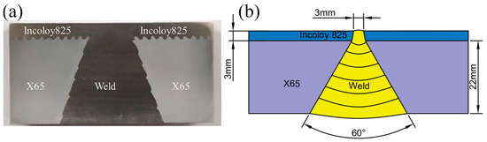
Figure 1.
Macroscopic drawing of welded joint of Incoloy825/X65 composite pipe: (a) test sample, (b) Schematic diagram of welding sequence.
Samples with a size of 10 mm × 10 mm × 2.5 mm were cut from the welded joints and included the base layer, the cladding, the heat-affected zone (HAZ), and the weld seam. The chemical immersion method was used to measure the pitting corrosion resistance of the welded joint of the Incoloy825/X65 bimetallic composite pipes. The immersion test was implemented in a high-temperature, high-pressure autoclave. The corrosion medium (suspended sulfur solution) was prepared by dispersing 10 g/L of S8 into 3.5 wt.% NaCl solution. The samples were ground and polished and then immersed in the corrosion medium at a test temperature of 90 °C and under an immersion cycle of 7 days, 14 days, and 21 days. After the test, an SEM was used to observe the corrosion product film and the pitting pit morphology on the surface of the specimen, while EDS was used to analyze the elemental composition of the corrosion product film to investigate its growth and mechanism.
3. Results and Discussion
3.1. The Corrosion Product Film’s Surface Microscopic Morphology
Figure 2 shows the corrosion morphology of different regions after 7 days of immersion. Table 2 shows the results of the EDS analysis of the corrosion product film. As can be seen in Figure 2, the corrosion product film on the surface of the specimen is not uniformly covered, and there are small particles scattered on the surface of the substrate. From the EDS analysis results, it can be seen that the corrosion product film on the surface of the specimen after 7 days of corrosion by sulfur is mainly composed of O, Fe, Cr, Ni, S, and other elements, of which the content of the O element is the highest, and the content of the S element is the lowest. The HAZ has the greatest amount of corrosion product, followed by the weld zone, and in the Incoloy825 region, the least corrosion occurs, which indicate that the heat-affected zone of the welding joint is the preferred region for sulfur corrosion. This might be due to the S2− or SO42− ions formed from the simple hydrolysis of the substance S at higher temperatures. Figure 3 shows the XRD pattern of the corrosion products, and it can be seen that the main components of the corrosion products are FeS, NiS, Fe2O3, FeSO4, and NiO.
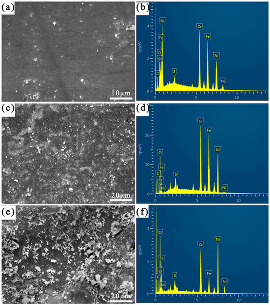
Figure 2.
SEM images of corrosion product film and corresponding EDS mapping images after corrosion for 7 days: (a,b) Incoloy825, (c,d) HAZ, and (e,f) weld zone.
Table 2.
Atomic percentage of corrosion product film after corrosion for 7 days.
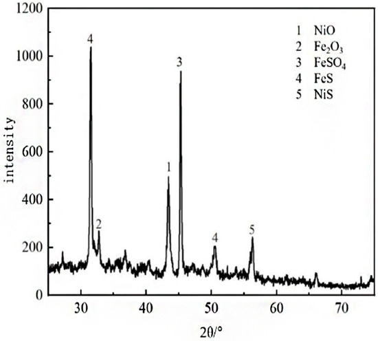
Figure 3.
XRD patterns of the corrosion products.
The metallic passivation films (the main components of NiO and Cr2O3) formed on the surface of nickel-based alloys can protect the substrate from corrosive ions. With a large number of corrosive ions gathered on the surface of the alloy, according to Macdonald’s point defect model [8], the oxygen vacancies in the passivation film on the surface of the alloy migrate to the junction between the passivation film and the corrosive medium, the polarity of S2− is higher than that of Cl− and OH−, and the S2− will be adsorbed into the oxygen vacancies first, and a small amount of dissolution occurs in the oxygen vacancies in the passivation film after they are occupied by S2−. After the partial dissolution of the passivation film, metal ions such as Ni2+, Fe2+, and Fe3+ in the nickel-based alloy matrix diffuse between the corrosion medium and the metal matrix, and Cr3+ is mainly distributed on the surface of the matrix as Cr2O3 [9]. From Figure 2, it can be seen that the Incoloy825 region and the HAZ have a high elemental content of Fe, Cr, and Ni, and the weld has a low elemental content of Fe. Metal cations such as Ni2+, Fe2+, and Fe3+ from the Incoloy825 region and the HAZ are combined with the S2− in the solution, and corrosion products such as FeS and NiS are formed on the surface of the specimen, and the corrosion products on the surface of the weld mainly consist of NiS. As shown in Table 2, after 7 days of immersion in the elemental sulfur corrosive environment, the HAZ’s surface contains the most S, which indicates that the bimetallic composite pipe’s welded joints in different regions experience different intensities of S elemental corrosion in the following descending order: the HAZ, the weld seam, and the Incoloy825 region. Moreover, there is a lack of the Cr element near the fusion line in the HAZ, which results in poor corrosion resistance in the heat-affected zone under the S element corrosion environment. The passivation film on the surface of the sample dissolves and forms sulfides.
The three-dimensional morphology of the corrosion in different areas of the welded joints of the bimetallic composite pipes after 7 days of immersion in the corrosive S element environment according to confocal microscopy is shown in Figure 4. It can be seen that the thickness of the corrosion product film is 1.5–3 μm, and the thickness of the product film is thin and unevenly distributed, and the average thickness of the product film in the different areas of the welded joints is in descending order as follows: the HAZ, the weld, and the Incoloy825 region.
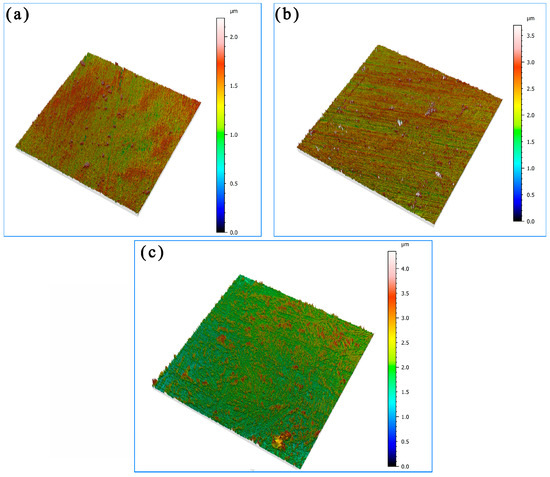
Figure 4.
Three-dimensional topography of the surface after corrosion for 7 days: (a) Incoloy825, (b) the HAZ, and (c) the weld zone.
Figure 5 shows the corrosion morphology of different areas of the welded joints after 14 days of immersion. Table 3 shows the results of the EDS analysis of the corrosion product film. As seen in Figure 5, with extension of the immersion time, the density and amount of corrosion products on the specimen’s surface increased. The HAZ’s surface was almost covered with the corrosion products. And the corrosion product on the weld zone’s surface presented highly and less staggered round particles.
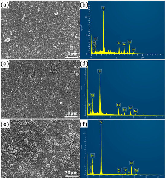
Figure 5.
SEM images of corrosion product film and corresponding EDS mapping images after corrosion for 14 days: (a,b) Incoloy825, (c,d) HAZ, and (e,f) weld zone.
Table 3.
Atomic percentage of corrosion product film after corrosion for 14 days.
As can be seen from Table 3, the content of the S and Ni elements in the corrosion product film was significantly increased after 14 days of immersion, while the content of the O elements decreased significantly. This indicates that the surface passivation film of the specimen was damaged, and the substrate was exposed to the corrosion medium for elemental sulfur corrosion. With an increase in the immersion time, the corrosion medium’s S2−, Cl−, and OH− ions competed for adsorption into the passivation membrane’s oxygen vacancies, prompting the passivation film to dissolve to form a large number of metal sulfides. The S2− on the passivation film’s surface migrated to the inner layer of the film with the help of the vacancies and reacted with the internal substrate. The sulfide concentration on the alloy surface was higher than the oxide concentration and more defective, and some pitting pits began to appear on the surface. With the accumulation of the corrosion medium, the pH value declined inside the pits, and an internal “occlusion battery” formed that accelerated the local corrosion. The composition of and structural change in the passivation film on the surface affected its self-repair function and pitting resistance, exacerbating the sulfur corrosion. With the occurrence of localized corrosion, the corrosion product covering the surface was gradually transformed from FeS to FeS2 [10,11].
The three-dimensional morphology of the corrosion in the different regions of the welded joint after 14 days of immersion is shown in Figure 6. It can be seen that the thickness of the corrosion product reached 3–6 μm. The corrosion product film in the HAZ was uniform, and its average thickness was the largest. And the average thickness of the corrosion product film in the Incoloy825 region was the smallest. After 14 days of immersion, the thickness of the product film on the surface of the weld zone was unevenly distributed and partially detached, which was due to the dendritic elemental segregation caused by the Laves phase in the weld region, resulting in a decrease in the corrosion resistance of the weld region. In addition, the Ni element content in the weld matrix was up to 60%, which continued to react with sulfur, generating a large amount of structurally loose NiS corrosion product. The NiS corrosion product had structural defects and was prone to detachment, as shown in Figure 6c.
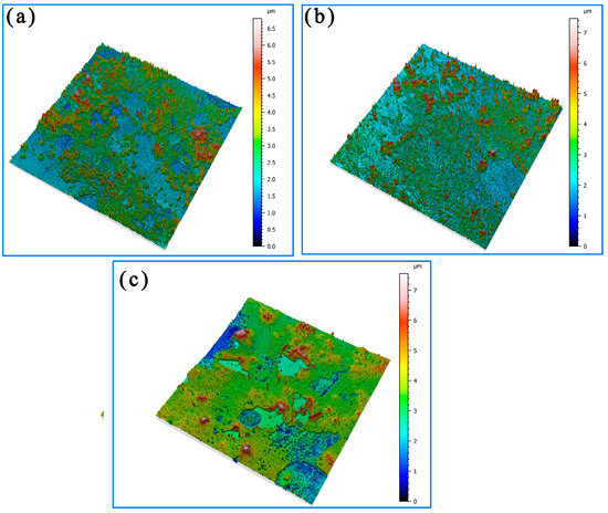
Figure 6.
Three-dimensional topography of the surface after corrosion for 14 days: (a) Incoloy825, (b) HAZ, and (c) weld zone.
Figure 7 shows the corrosion morphology of the different areas of the welding joint after 21 days of immersion. Table 4 shows the results of the EDS analysis of the corrosion product films in different areas of the joint after 21 days of immersion. It can be seen that the surface of the Incoloy825 region was interspersed with particles formed by Cr and Ni oxides and sulfides and some fibrous corrosion products composed of the Ni, O, and S elements. On the surface of the HAZ, large-sized granular corrosion products consisting of the Cr, O, and S elements were distributed. The surface of the weld zone continuously generated loose and porous NiS, and the corrosion product film had serious cracks [6].
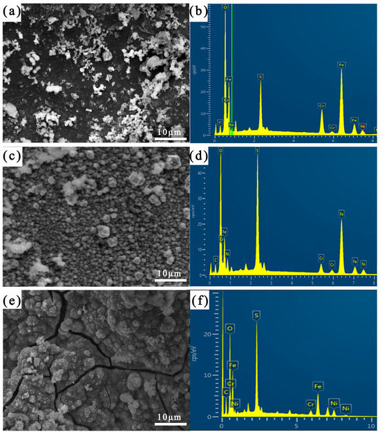
Figure 7.
SEM images of corrosion product film and corresponding EDS mapping images after corrosion for 21 days: (a,b) Incoloy825, (c,d) HAZ, and (e,f) weld zone.
Table 4.
Atomic percentage of corrosion product film after corrosion for 21 days.
The corrosion product film on the nickel-based alloy’s surface in sulfur-containing environments has a double-layer structure, with the outer layer consisting of NiS and Cr2S3 and the inner layer dominated by chromium and nickel oxides [8,9]. The Cr2S3 possessed a stable structure and could act in conjunction with the inner membrane oxide to protect the substrate [12]. In the process of the localized corrosion of the occlusion cell, the chromium ions inside the nickel-based alloy matrix were continuously released and diffused into the matrix/corrosion layer interface. Compared with the nickel element, O2− and S2− were more inclined to react with Cr to form structurally stable Cr2S3, thus inhibiting the generation of nickel sulfide [13]. As the corrosion process continued, Ni2+, Fe2+, Cr3+, and other metal ions were consumed and dissolved in the corrosion medium, which led to a substantial decrease in the content of metal elements in the corrosion product film.
Figure 8 shows the three-dimensional morphology of the corrosion in different areas of the welded joints after 21 days of immersion. It can be seen that the average thickness of the corrosion product film increased, and the corrosion product film’s morphology tended to be flat. The average thickness of the product film on the surface of the Incoloy825 region, the HAZ, and the weld zone all reached 7–13 μm. The density of the corrosion product film in the Incoloy825 region and the HAZ was greater than that in the weld seam area.
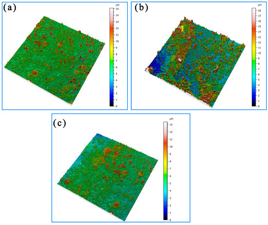
Figure 8.
Three-dimensional topography of the surface after corrosion for 21 days: (a) Incoloy825, (b) HAZ, and (c) weld zone.
The intersection of the three zones in the weld joint of the bimetallic composite pipe undergoes two thermal cycles, leading to a high concentration of thermal residual stress [14]. In a sulfur corrosion environment, the residual stress will internally reduce the corrosion resistance of the surface [9]. Meanwhile, due to the difference in the composition and corrosion rates among the different areas of the welded joint, the corrosion product film collapsed to the side with a faster corrosion rate, as shown in Figure 9.
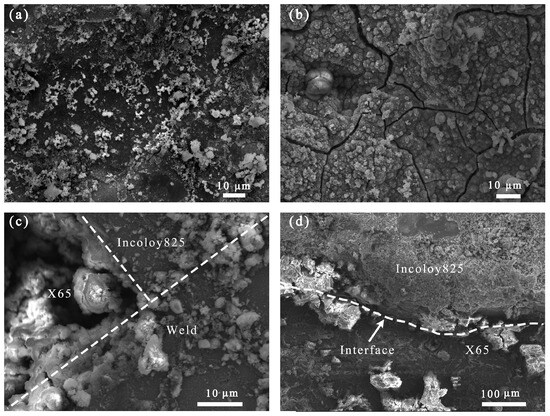
Figure 9.
Morphology of corrosion product film after corrosion for 21 days: (a) Incoloy825 region, (b) weld zone, (c) three-phase region, and (d) interface.
3.2. Evolution of Pitting Corrosion
Figure 10 shows the three-dimensional morphology of the pitting pits on the matrix surface in the localized area of the welded joint of the bimetallic composite pipe. After immersion in the sulfur solution for 7 days, the average depth of the corrosion pits on the substrate’s surface was 0.5 μm. After 14 days of immersion, the average depth of these corrosion pits increased to 5 μm. After 21 days of immersion, the average depth of the corrosion pits reached 10 μm. And as the immersion time was prolonged, the depth–diameter ratio of the corrosion pits significantly decreased. In the initial stage of the substrate surface’s corrosion, once the corrosion pits had formed, the metal surface inside the pits became active with a more negative potential. And the metal surface outside the pits remained passive with a more positive potential; hence, the pits served as an anode, and the surface outside the pits served as a cathode. This created a localized galvanic corrosion cell, known as an activation–passivation cell, with a large cathode and a small anode area, promoting the expansion of the corrosion pits. Due to the large number of corrosive ions on the surface of the passivation film, while the bottom of the pits contained fewer ions, the corrosion rate of the metal cations in the surface layer was greater than that in the bottom of the pits. With relatively small pit areas, the medium’s transmission inside the pits was essentially stagnant. The diffusion and transfer of corrosive ions such as S2−, Cl−, and OH− from the corrosive medium to the metal cations inside the pits were hindered. This led to an increase in the concentration of the metal ions within the pits, causing a change in the composition and potential of the medium in the pits. To maintain the neutrality of the solution, chloride ions continuously migrated into the pits. As the reaction proceeded, the corrosive product FeCl2 accumulated within the pits. FeCl2 was hydrolyzed to form hydrochloric acid, causing a decrease in the pH of the medium within the pits [15]. The accumulation of high-concentration acidic solution enriched with Cl− inside the pits accelerated anodic dissolution, promoting the development of the pits in the direction of depth through a “self-catalytic acidification process” within the closed cell.
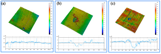
Figure 10.
The morphology and average depth of the corrosion pit: (a) immersion for 7 days, (b) immersion for 14 days, and (c) immersion for 21 days.
4. Conclusions
In the suspended sulfur corrosion environment, the heat-affected zone (HAZ) of the welding joint of Incoloy825/X65 bimetal composite pipes is the preferred region for pitting. The most severe local corrosion occurs in the weld zone of the joint of the bimetallic composite pipe during long-running corrosion. The change in the composition and structure of the corrosion product film affects the corrosion resistance. The oxide film on the surface of the nickel-based alloy first transforms from nickel and chromium oxides to loose and porous nickel sulfide. With an increase in the immersion time, the corrosion products on the surface of the nickel-based alloy change into structurally dense NiS, FeS, and Cr2S3, as well as NiO, Fe2O3, and others, hindering the further development of sulfur corrosion.
Author Contributions
Conceptualization: Y.S. and S.Y. Methodology: B.W. and E.L. Software: T.F. Validation: L.L., Y.S. and T.F. Formal analysis: E.L. Investigation: S.Y. Resources: B.W. Data curation: Y.S. and L.L. Writing—original draft preparation: Y.S. Writing—review and editing: Y.S. Visualization: T.F. and E.L. Supervision: B.W. and E.L. Project administration: S.Y. Funding acquisition: E.L. All authors have read and agreed to the published version of the manuscript.
Funding
This work was supported by the Natural Science Foundation of Shandong Province of China (Grant No. ZR2024QE023).
Data Availability Statement
The data presented in this study are available on request from the corresponding author. The data are not publicly available due to privacy.
Conflicts of Interest
The authors declare no conflicts of interest. Author Y.S. was employed by Petro China Southwest Oil and Gas field Company, Institute of Safety, Environmental Protection and Technical Supervision. The remaining authors declare that the research was conducted in the absence of any commercial or financial relationships that could be construed as a potential conflict of interest.
References
- Li, F.; Feng, D.; Wang, J.W.; Gao, D.L. The Using of Anti-Sulfur Drill Pipe in High Sulfur Oil-Gas Field. Adv. Mater. Res. 2012, 383, 1776–1780. [Google Scholar] [CrossRef]
- Qin, M.; Liao, K.; He, G.; Zou, Q.; Zhao, S.; Zhang, S. Corrosion mechanism of X65 steel exposed to H2S/CO2 brine and H2S/CO2 vapor corrosion environments. J. Nat. Gas Sci. Eng. 2022, 106, 104774. [Google Scholar] [CrossRef]
- Song, F.M. A comprehensive model for predicting CO2 corrosion rate in oil and gas production and transportation systems. Electrochim. Acta 2010, 55, 689–700. [Google Scholar] [CrossRef]
- Wang, C.; Bi, Z.Y.; Zhang, W.P.; Yang, Y.B.; Han, C.C. Research status on double-metal composite pipe at home and abroad. Welded Pipe Tube 2015, 38, 7–12. [Google Scholar]
- Bin WE, I.; Helin, L.I.; Fagen, L.I. Research status and prospects of bimetallic composite pipes for submarine oil and gas transmission. Oil Gas Storage Transp. 2016, 35, 343–355. [Google Scholar]
- Wang, B.; Ouyang, L.; Xu, J.; Huang, P.; Liu, E.; Yang, B. Study on stress corrosion cracking behavior of Incoloy825/X65 bimetallic composite pipe welded joint in wet hydrogen sulfide environment. Metals 2022, 12, 632. [Google Scholar] [CrossRef]
- Chen, H.; Ma, H.; Chen, X.; Jiang, S.; Wang, H. Failure Analysis of Butt Weld of Bimetal Composite Pipes. J. Fail. Anal. Prev. 2015, 15, 563–570. [Google Scholar]
- Macdonald, D.D. The history of the Point Defect Model for the passive state: A brief review of film growth aspects. Electrochim. Acta 2011, 56, 1761–1772. [Google Scholar]
- Changfeng, C.; Ruijing, J.; Guoan, Z.; Shuqi, Z.; Lei, G. Study on local corrosion of nickel-base alloy tube in the environment of high temperature and high pressure H2S/CO2. Rare Met. Mater. Eng. 2010, 39, 427–432. [Google Scholar]
- Schmitt, G. Effect of elemental sulfur on corrosion in sour gas systems. Corrosion 1991, 47, 285–308. [Google Scholar] [CrossRef]
- Fang, H.; Young, D.; Nesic, S. Corrosion of mild steel in the presence of elemental sulfur. In Proceedings of the Nace Corrosion 2008 Conference & Expo, New Orleans, LA, USA, 16–20 March 2008. [Google Scholar]
- Cheng, Q.G.; Jianting, L.; Weiliang, X.; Yang, T.; Liu, Z.; Wang, Y.; Shi, Y. Molybdenum addition enhancing the corrosion resistance of Ni16Cr alloy in aqueous solution. IOP Conf. Ser. Earth Environ. Sci. 2019, 310, 042010. [Google Scholar]
- Kim, M.J.; Lee, D.B. High-temperature corrosion of aluminized and chromized Fe-10.4%Cr steels in N2/H2S/H2O-mixed gas. Mater. Corros. 2016, 67, 201508638. [Google Scholar]
- Jiang, W.; Chen, W.; Woo, W.; Tu, S.-T.; Zhang, X.-C.; Em, V. Effects of low-temperature transformation and transformation-induced plasticity on weld residual stresses: Numerical study and neutron diffraction measurement. Mater. Des. 2018, 147, 65–79. [Google Scholar] [CrossRef]
- Reffass, M.; Sabot, R.; Savall, C.; Jeannin, M.; Creus, J.; Refait, P. Localised corrosion of carbon steel in NaHCO3/NaCl electrolytes: Role of Fe(II)-containing compound. Corros. Sci. 2006, 48, 709–726. [Google Scholar] [CrossRef]
Disclaimer/Publisher’s Note: The statements, opinions and data contained in all publications are solely those of the individual author(s) and contributor(s) and not of MDPI and/or the editor(s). MDPI and/or the editor(s) disclaim responsibility for any injury to people or property resulting from any ideas, methods, instructions or products referred to in the content. |
© 2025 by the authors. Licensee MDPI, Basel, Switzerland. This article is an open access article distributed under the terms and conditions of the Creative Commons Attribution (CC BY) license (https://creativecommons.org/licenses/by/4.0/).