
Phase Composition, Surface Morphology, and Dielectric Properties of Poly(Vinylidene Fluoride)–Cobalt Ferrite Composite Films Depending on Thickness

 , ,
, ,  , ,
, , 

Highlights
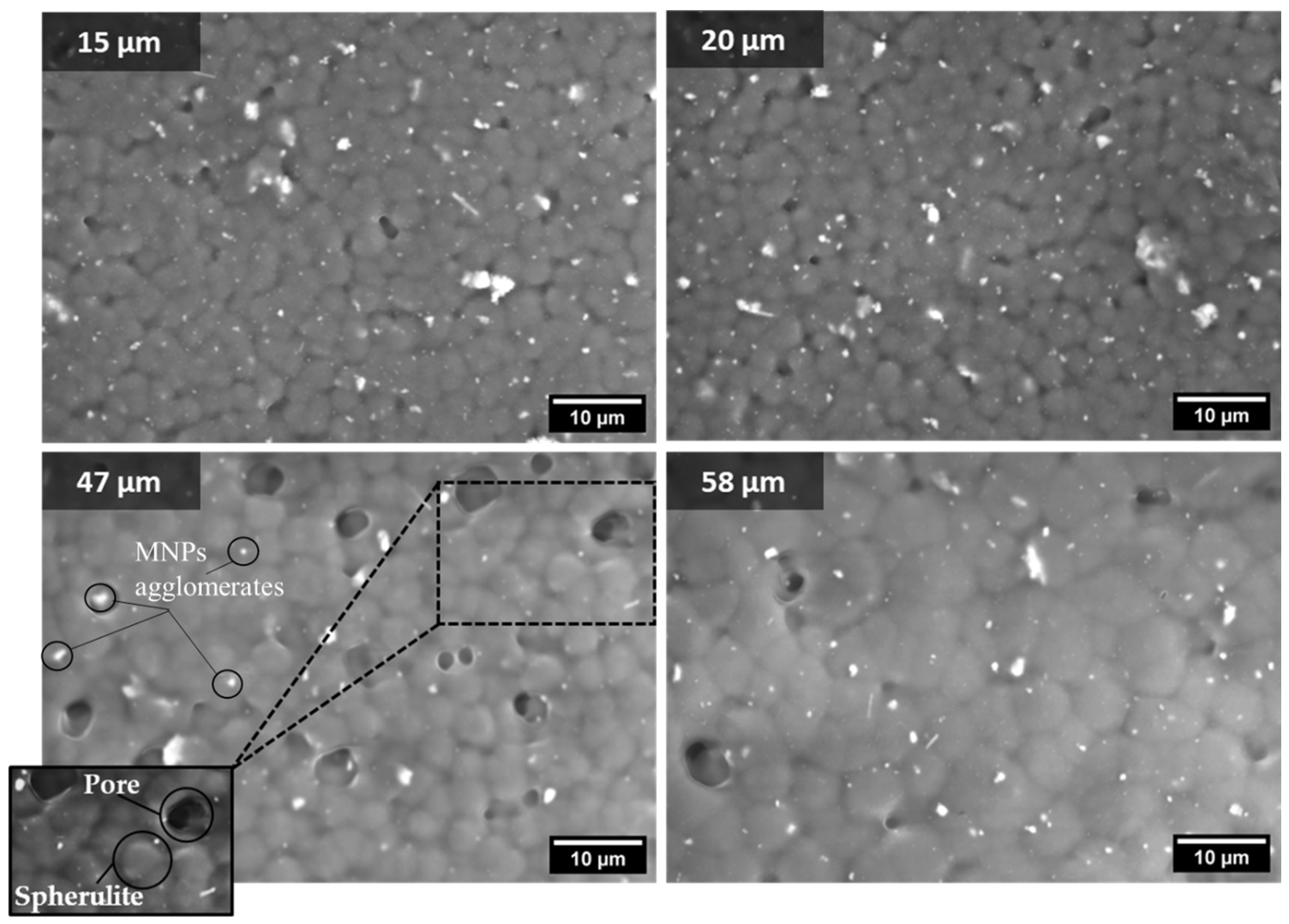
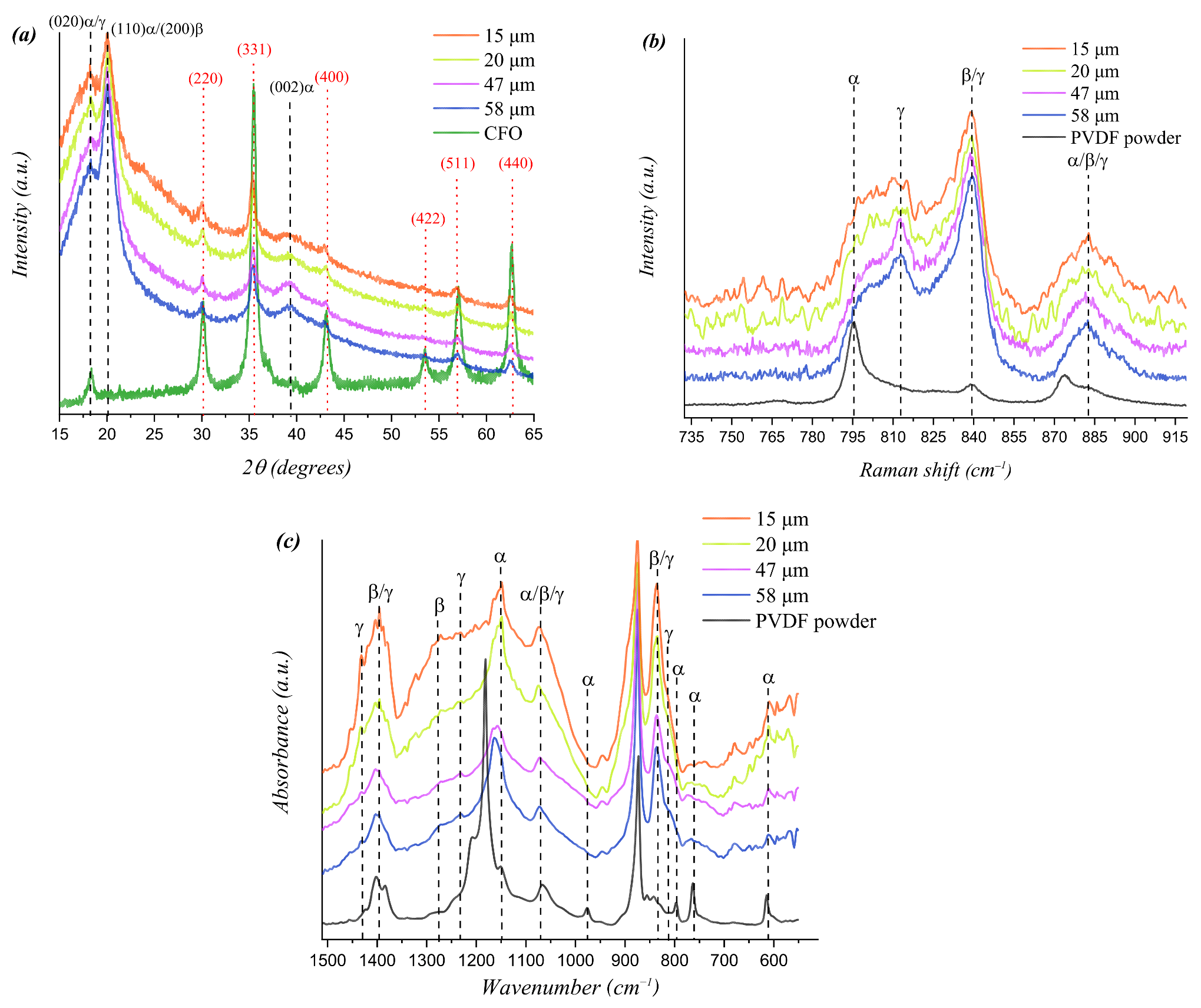
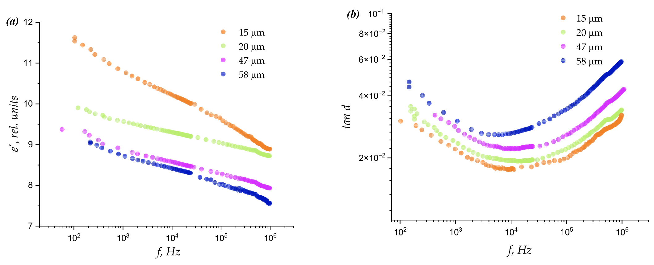
- Thinner PVDF-CoFe2O4 composite films exhibited smaller spherulite and pore sizes. A decrease in elasticity was observed for films less than 58 μm, with Young's modulus decreasing from 45 MPa to 29–33 MPa at thicknesses of 47, 20 and 15 μm. FTIR spectroscopy showed that the β-phase content was higher in thin films (42%) compared to thicker films (5%). Thin films with more β-phase and fewer pores had improved dielectric properties.
- The study highlights the importance of film thickness control in optimising β-phase content and dielectric properties in PVDF-CFO composite films. The results provide insight into how film thickness affects the phase composition, surface morphology and dielectric properties of PVDF-CFO composite films as a function of thickness. These principles can be applied to other PVDF-based composite systems to tailor material properties for specific applications. The results show that thinner films with higher β-phase content are more suitable for applications requiring a high dielectric constant and electrical activity. This is critical for the development of advanced sensor and energy harvesting devices.
Abstract

1. Introduction
2. Experiment Design
2.1. Materials
2.2. Nanoparticles Synthesis
2.3. Fabrication of PVDF-CFO Composite Films
2.4. Characterization
3. Results and Discussion
4. Conclusions
Supplementary Materials
Author Contributions
Funding
Data Availability Statement
Acknowledgments
Conflicts of Interest
References
- Zapsas, G.; Patil, Y.; Gnanou, Y.; Ameduri, B.; Hadjichristidis, N. Poly(Vinylidene Fluoride)-Based Complex Macromolecular Architectures: From Synthesis to Properties and Applications. Prog. Polym. Sci. 2020, 104, 101231. [Google Scholar] [CrossRef]
- Liu, R.; Yuan, B.; Zhong, S.; Liu, J.; Dong, L.; Ji, Y.; Dong, Y.; Yang, C.; He, W. Poly(Vinylidene Fluoride) Separators for Next-generation Lithium Based Batteries. Nano Sel. 2021, 2, 2308–2345. [Google Scholar] [CrossRef]
- Shirinov, A.V.; Schomburg, W.K. Pressure Sensor from a PVDF Film. Sens. Actuators A Phys. 2008, 142, 48–55. [Google Scholar] [CrossRef]
- Toda, M.; Thompson, M.L. Contact-Type Vibration Sensors Using Curved Clamped PVDF Film. IEEE Sens. J. 2006, 6, 1170–1177. [Google Scholar] [CrossRef]
- Liu, F.; Hashim, N.A.; Liu, Y.; Abed, M.R.M.; Li, K. Progress in the Production and Modification of PVDF Membranes. J. Membr. Sci. 2011, 375, 1–27. [Google Scholar] [CrossRef]
- Tan, X.M.; Rodrigue, D. A Review on Porous Polymeric Membrane Preparation. Part I: Production Techniques with Polysulfone and Poly(Vinylidene Fluoride). Polymers 2019, 11, 1160. [Google Scholar] [CrossRef] [PubMed]
- Lovinger, A.J. Ferroelectric Polymers. Science 1983, 220, 1115–1121. [Google Scholar] [CrossRef] [PubMed]
- Zhou, H.; Wang, H.; Liu, Z.; Yang, H.; Yuan, C.; Wang, Y. Facilitated Phase Transformation of PVDF in Its Composite with an Ionic Liquid. Polymer 2021, 220, 123564. [Google Scholar] [CrossRef]
- Kalimuldina, G.; Turdakyn, N.; Abay, I.; Medeubayev, A.; Nurpeissova, A.; Adair, D.; Bakenov, Z. A Review of Piezoelectric Pvdf Film by Electrospinning and Its Applications. Sensors 2020, 20, 5214. [Google Scholar] [CrossRef]
- Gérard, J. Structural Dependence of Cations and Anions to Building the Polar Phase of PVDF. Eur. Polym. J. 2018, 107, 236–248. [Google Scholar] [CrossRef]
- Silva, M.P.; Sencadas, V.; Botelho, G.; Machado, A.V.; Rolo, A.G.; Rocha, J.G.; Lanceros-Méndez, S. α- and γ-PVDF: Crystallization Kinetics, Microstructural Variations and Thermal Behaviour. Mater. Chem. Phys. 2010, 122, 87–92. [Google Scholar] [CrossRef]
- Song, T.; Wang, S.; Wang, H.; Sun, X.; Li, H.; Yan, S. Effect of Illite on Crystallization of Poly(Vinylidene Fluoride). Ind. Eng. Chem. Res. 2020, 59, 3438–3445. [Google Scholar] [CrossRef]
- Van Krevelen, D.W. Properties of Polymers: Their Correlation with Chemical Structure; Their Numerical Estimation and Prediction from Additive Group Contributions, 4th ed.; Elsevier Science: Amsterdam, Netherlands, 2009; ISBN 9780080548197. [Google Scholar]
- Lima, A.C.; Lanceros-Méndez, S.; Martins, P. Magnetoelectrics: Three Centuries of Research. Materials 2020, 13, 4033. [Google Scholar] [CrossRef] [PubMed]
- Koç, M.; Dönmez, Ç.E.D.; Paralı, L.; Sarı, A.; Aktürk, S. Piezoelectric and Magnetoelectric Evaluations on PVDF/CoFe2O4based Flexible Nanogenerators for Energy Harvesting Applications. J. Mater. Sci. Mater. Electron. 2022, 33, 8048–8064. [Google Scholar] [CrossRef]
- Xue, W.; Lv, C.; Jing, Y.; Chen, F.; Fu, Q. Fabrication of Electrospun PVDF Nanofibers with Higher Content of Polar β Phase and Smaller Diameter by Adding a Small Amount of Dioctadecyl Dimethyl Ammonium Chloride. Chin. J. Polym. Sci. 2017, 35, 992–1000. [Google Scholar] [CrossRef]
- Vicente, J.; Costa, P.; Lanceros-Méndez, S.; Abete, J.M.; Iturrospe, A. Electromechanical Properties of PVDF-Based Polymers Reinforced with Nanocarbonaceous Fillers for Pressure Sensing Applications. Materials 2019, 12, 3545. [Google Scholar] [CrossRef]
- Zhang, X.; Xia, W.; Liu, J.; Zhao, M.; Li, M.; Xing, J. PVDF-Based and Its Copolymer-Based Piezoelectric Composites: Preparation Methods and Applications. J. Electron. Mater. 2022, 51, 5528–5549. [Google Scholar] [CrossRef]
- Martins, P.; Lasheras, A.; Gutierrez, J.; Barandiaran, J.M.; Orue, I.; Lanceros-Méndez, S. Optimizing Piezoelectric and Magnetoelectric Responses on CoFe2O4/P(VDF-TrFE) Nanocomposites. J. Phys. D Appl. Phys. 2011, 44, 495303. [Google Scholar] [CrossRef]
- Wang, Y.; Zhu, L.; Du, C. Progress in Piezoelectric Nanogenerators Based on Pvdf Composite Films. Micromachines 2021, 12, 1278. [Google Scholar] [CrossRef] [PubMed]
- Jovanović, S.; Spreitzer, M.; Otoničar, M.; Jeon, J.H.; Suvorov, D. PH Control of Magnetic Properties in Precipitation-Hydrothermal-Derived CoFe2O4. J. Alloys Compd. 2014, 589, 271–277. [Google Scholar] [CrossRef]
- Ribeiro, C.; Costa, C.M.; Correia, D.M.; Nunes-Pereira, J.; Oliveira, J.; Martins, P.; Gonçalves, R.; Cardoso, V.F.; Lanceros-Méndez, S. Electroactive Poly(Vinylidene Fluoride)-Based Structures for Advanced Applications. Nat. Protoc. 2018, 13, 681–704. [Google Scholar] [CrossRef] [PubMed]
- Stan, G.; King, S.W. Atomic Force Microscopy for Nanoscale Mechanical Property Characterization. J. Vac. Sci. Technol. B Nanotechnol. Microelectron. Mater. Process. Meas. Phenom. 2020, 38, 060801. [Google Scholar] [CrossRef]
- Holzwarth, U.; Gibson, N. The Scherrer Equation versus the “Debye-Scherrer Equation”. Nat. Nanotechnol. 2011, 6, 534. [Google Scholar] [CrossRef] [PubMed]
- Salnikov, V.D.; Aga-Tagieva, S.E.; Kolesnikova, V.G.; Tovpinets, A.O.; Omelyanchik, A.S.; Rodionova, V.V. Effect of PEG Nanoparticle Surface Coating on the Magnetic and Structural Properties of CoFe2O4/PVDF Composites. J. Magn. Magn. Mater. 2024, 595, 171498. [Google Scholar] [CrossRef]
- Mooti, A.; Costa, C.M.; Maceiras, A.; Pereira, N.; Tubio, C.R.; Vilas, J.L.; Besbes-Hentati, S.; Lanceros-Méndez, S. Magnetic and High-Dielectric-Constant Nanoparticle Polymer Tri-Composites for Sensor Applications. J. Mater. Sci. 2020, 55, 16234–16246. [Google Scholar] [CrossRef]
- Gregorio, R.; Ueno, E.M. Effect of Crystalline Phase, Orientation and Temperature on the Dielectric Properties of Poly(Vinylidene Fluoride) (PVDF). J. Mater. Sci. 1999, 34, 4489–4500. [Google Scholar] [CrossRef]
- Hashim, M.; Alimuddin; Shirsath, S.E.; Kumar, S.; Kumar, R.; Roy, A.S.; Shah, J.; Kotnala, R.K. Preparation and Characterization Chemistry of Nano-Crystalline Ni–Cu–Zn Ferrite. J. Alloys Compd. 2013, 549, 348–357. [Google Scholar] [CrossRef]
- Goldman, A. Modem Ferrite Technology; Springer: New York, NY, USA, 2006; ISBN 9780387281513. [Google Scholar]
- Mahato, P.K.; Seal, A.; Garain, S.; Sen, S. Effect of Fabrication Technique on the Crystalline Phase and Electrical Properties of PVDF Films. Mater. Sci. Pol. 2015, 33, 157–162. [Google Scholar] [CrossRef]
- Lei, T.; Cai, X.; Wang, X.; Yu, L.; Hu, X.; Zheng, G.; Lv, W.; Wang, L.; Wu, D.; Sun, D.; et al. Spectroscopic Evidence for a High Fraction of Ferroelectric Phase Induced in Electrospun Polyvinylidene Fluoride Fibers. RSC Adv. 2013, 3, 24952–24958. [Google Scholar] [CrossRef]
- Dong, L.; Liu, X.D.; Xiong, Z.R.; Sheng, D.K.; Zhou, Y.; Yang, Y.M. Preparation and Characterization of UV-Absorbing PVDF Membranes via Pre-Irradiation Induced Graft Polymerization. Chin. J. Polym. Sci. 2019, 37, 493–499. [Google Scholar] [CrossRef]
- Constantino, C.J.L.; Job, A.E.; Simões, R.D.; Simões, S.; Giacometti, J.A.; Zucolotto, V.; Oliveira, O.N.; Gozzi, G.; Chinaglia, D.L. Phase Transition in Poly(Vinylidene Fluoride) Investigated with Micro-Raman Spectroscopy. Appl. Spectrosc. 2005, 59, 275–279. [Google Scholar] [CrossRef] [PubMed]
- Bormashenko, Y.; Pogreb, R.; Stanevsky, O.; Bormashenko, E. Vibrational Spectrum of PVDF and Its Interpretation. Polym. Test. 2004, 23, 791–796. [Google Scholar] [CrossRef]
- Cai, X.; Lei, T.; Sun, D.; Lin, L. A Critical Analysis of the α, β and γ Phases in Poly(Vinylidene Fluoride) Using FTIR. RSC Adv. 2017, 7, 15382–15389. [Google Scholar] [CrossRef]
- Sharifi Dehsari, H.; Kumar, M.; Saad, A.; Hassanpour Amiri, M.; Yan, C.; Anwar, S.; Glasser, G.; Asadi, K. Thin-Film Polymer Nanocomposites for Multiferroic Applications. ACS Appl. Nano Mater. 2018, 1, 6247–6257. [Google Scholar] [CrossRef]
- Nguyen, A.N.; Solard, J.; Nong, H.T.T.; Osman, C.B.; Gomez, A.; Bockelée, V.; Tencé-Girault, S.; Schoenstein, F.; Simón-Sorbed, M.; Carrillo, A.E.; et al. Spin Coating and Micro-Patterning Optimization of Composite Thin Films Based on PVDF. Materials 2020, 13, 1342. [Google Scholar] [CrossRef] [PubMed]
- Xia, W.; Yin, Y.; Zhang, Z.; Xu, Z. The Magnetoelectric Effect of the CFO Thin Film by Coupling a P(VDF- Co -TrFE) Piezoelectric Layer. J. Appl. Phys. 2018, 124, 154102. [Google Scholar] [CrossRef]
- Singh, P.; Borkar, H.; Singh, B.P.; Singh, V.N.; Kumar, A. Electro-Mechanical Properties of Free Standing Micro- and Nano-Scale Polymer-Ceramic Composites for Energy Density Capacitors. J. Alloys Compd. 2015, 648, 698–705. [Google Scholar] [CrossRef]
- Kisiel, A.; Konieczny, M.; Zabska, M. Dielectric Properties of Polymer Composites with the Addition of Ferrite Nanoparticles. IOP Conf. Ser. Mater. Sci. Eng. 2016, 113, 012002. [Google Scholar] [CrossRef]
- Gao, R.; Wang, Z.; Chen, G.; Deng, X.; Cai, W.; Fu, C. Influence of Core Size on the Multiferroic Properties of CoFe2O4@BaTiO3 Core Shell Structured Composites. Ceram. Int. 2018, 44, S84–S87. [Google Scholar] [CrossRef]
- Gheorghiu, F.; Stanculescu, R.; Curecheriu, L.; Brunengo, E.; Stagnaro, P.; Tiron, V.; Postolache, P.; Buscaglia, M.T.; Mitoseriu, L. PVDF–ferrite Composites with Dual Magneto-Piezoelectric Response for Flexible Electronics Applications: Synthesis and Functional Properties. J. Mater. Sci. 2020, 55, 3926–3939. [Google Scholar] [CrossRef]
- Slimani, S.; Talone, A.; Abdolrahimi, M.; Imperatori, P.; Barucca, G.; Fiorani, D.; Peddis, D. Morpho-Structural and Magnetic Properties of CoFe2O4/SiO2 Nanocomposites: The Effect of the Molecular Coating. J. Phys. Chem. C 2023, 127, 8840–8849. [Google Scholar] [CrossRef]


| Thickness (μm) | Average Spherulites Size (μm) | Average Pore Size (μm) |
|---|---|---|
| 15 | 2.7 ± 0.3 | 1.2 ± 0.2 |
| 20 | 2.6 ± 0.3 | 1.3 ± 0.3 |
| 47 | 3.7 ± 0.5 | 2.5 ± 0.7 |
| 58 | 5.5 ± 1.2 | 2.6 ± 0.6 |
| Thickness (μm) | Young’s Modulus (MPa) | Deformation (nm) | Rq (nm) |
|---|---|---|---|
| 15 | 29 ± 2 | 70 ± 3 | 132 |
| 20 | 33 ± 1 | 64 ± 1 | 125 |
| 47 | 30 ± 2 | 68 ± 3 | 162 |
| 58 | 45 ± 4 | 50 ± 1 | 127 |
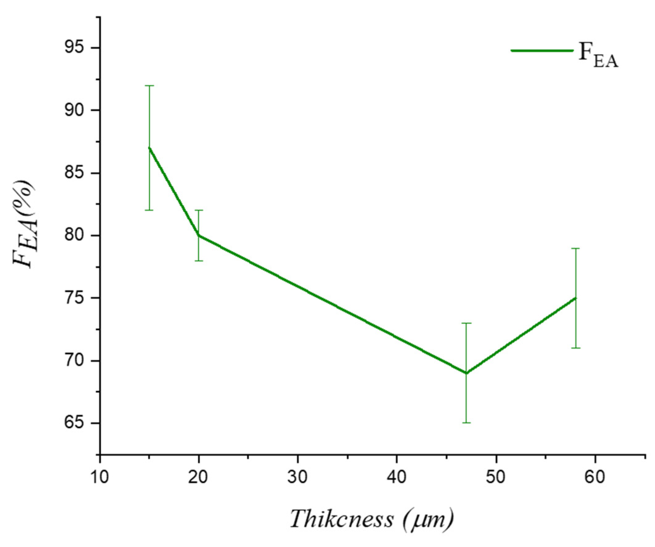
| Thickness (μm) | FEA (%) | α-phase (%) | β-Phase (%) | γ-Phase (%) |
|---|---|---|---|---|
| 15 | 87 ± 5 | 13 ± 5 | 42 ± 4 | 45 ± 4 |
| 20 | 80 ± 2 | 20 ± 2 | 29 ± 2 | 51 ± 2 |
| 47 | 69 ± 4 | 31 ± 4 | 4 ± 2 | 65 ± 4 |
| 58 | 75 ± 4 | 25 ± 4 | 5 ± 1 | 70 ± 4 |
Disclaimer/Publisher’s Note: The statements, opinions and data contained in all publications are solely those of the individual author(s) and contributor(s) and not of MDPI and/or the editor(s). MDPI and/or the editor(s) disclaim responsibility for any injury to people or property resulting from any ideas, methods, instructions or products referred to in the content. |
© 2024 by the authors. Licensee MDPI, Basel, Switzerland. This article is an open access article distributed under the terms and conditions of the Creative Commons Attribution (CC BY) license (https://creativecommons.org/licenses/by/4.0/).
Share and Cite
Vorontsov, P.A.; Salnikov, V.D.; Savin, V.V.; Vorontsov, S.A.; Omelyanchik, A.S.; Shvets, P.V.; Panina, L.V.; Ershov, P.A.; Rodionova, V.V. Phase Composition, Surface Morphology, and Dielectric Properties of Poly(Vinylidene Fluoride)–Cobalt Ferrite Composite Films Depending on Thickness. Crystals 2025, 15, 47. https://doi.org/10.3390/cryst15010047
Vorontsov PA, Salnikov VD, Savin VV, Vorontsov SA, Omelyanchik AS, Shvets PV, Panina LV, Ershov PA, Rodionova VV. Phase Composition, Surface Morphology, and Dielectric Properties of Poly(Vinylidene Fluoride)–Cobalt Ferrite Composite Films Depending on Thickness. Crystals. 2025; 15(1):47. https://doi.org/10.3390/cryst15010047
Chicago/Turabian StyleVorontsov, Pavel A., Vitalii D. Salnikov, Valerii V. Savin, Stanislav A. Vorontsov, Alexander S. Omelyanchik, Petr V. Shvets, Larissa V. Panina, Petr A. Ershov, and Valeria V. Rodionova. 2025. "Phase Composition, Surface Morphology, and Dielectric Properties of Poly(Vinylidene Fluoride)–Cobalt Ferrite Composite Films Depending on Thickness" Crystals 15, no. 1: 47. https://doi.org/10.3390/cryst15010047
APA StyleVorontsov, P. A., Salnikov, V. D., Savin, V. V., Vorontsov, S. A., Omelyanchik, A. S., Shvets, P. V., Panina, L. V., Ershov, P. A., & Rodionova, V. V. (2025). Phase Composition, Surface Morphology, and Dielectric Properties of Poly(Vinylidene Fluoride)–Cobalt Ferrite Composite Films Depending on Thickness. Crystals, 15(1), 47. https://doi.org/10.3390/cryst15010047