Article

Effect of Sulphate-Reducing Bacteria Activity on the Performance of Thermally Sprayed Aluminium and Polyurethane Coatings

1
TECNALIA, Basque Research and Technology Alliance (BRTA), Mikeletegi Pasealekua 2, 20009 Donostia-San Sebastián, Spain
2
Vicinay Marine Innovación, Plaza Ibaiondo 1, 48940 Leioa, Spain
3
Chemical and Environmental Engineering Department, Engineering Faculty of Bilbao, University of the Basque Country (UPV/EHU), Plaza Ingeniero Torres Quevedo 1, 48013 Bilbao, Spain
*
Author to whom correspondence should be addressed.
Crystals 2024, 14(3), 260; https://doi.org/10.3390/cryst14030260
Submission received: 19 February 2024 / Revised: 29 February 2024 / Accepted: 2 March 2024 / Published: 6 March 2024
(This article belongs to the Special Issue Corrosion and Oxidation of Alloys)

Abstract

:
In the present work, we studied whether the exposure of synthetic seawater with anaerobic sulphate-reducing bacteria (SRB) on some steel samples generates a bacterial biofilm in their surfaces. Bare steel belonging to a mooring chain as well as two coating systems applied on the steel surface were studied: polyurethane (PU) and thermally sprayed aluminium (TSA) with and without an epoxy-based sealant. After 30 days of immersion in SRB-inoculated synthetic seawater, a bacterial count was attained, and the samples were observed using scanning electron microscopy (SEM) and locally analysed using X-ray scattered energy spectroscopy (EDS). A biofilm developed on every tested surface (continuous or in the form of pustules), with evidence of metabolic activity of the SRB. Finally, a mechanism of degradation for TSA in the presence of SRB is proposed for environments with a high concentration of bacteria.

1. Introduction

Microbiologically influenced corrosion (MIC) can be defined as a corrosion process led by bacteria that causes the degradation of materials through the interaction of the three main constituents of this system: the metallic component, the electrolyte and the biological organisms. The occurrence of MIC in seawater-immersed low-alloy steel is common due to the very wide availability of microorganisms with an adequate supply of nutrients and corrosive products [1]. Therefore, bacterial interactions with diverse materials and surfaces occur in so many different ways that make the complexity of the system too high to be evaluated using standard corrosion model predictions [2]. Seawater is also a complex chemical system affected by many environmental factors, the most significant being the pH, the dissolved oxygen concentration, the temperature, and the biological species [3]. The presence of sulphate-reducing bacteria (SRB) and other types of microorganisms such as iron-oxidising bacteria has been identified as the main reason for multiple corrosion problems in seawater [1]. Their presence leads to a rapid surface colonisation, forming a cover which attacks the metal surface, replicating and producing exopolymers (EPSs) and ending in the formation of a cohesive structure called biofilm.
The mechanism of anaerobic iron oxidation through SRB, also known as cathodic depolarisation, is well known in carbon steel, and involves the consumption of the atomic hydrogen on the metal surface, occurring according to the following equations [4]:
Anodic reaction: 4Fe → 4Fe2+ + 8e
Water dissociation: 8H2O → 8H+ + 8OH
Cathodic reaction (metallic surface): 8H+ + 8e → 4H2
SRB-influenced cathodic depol.: SO42− + 4H2 → H2S + 2H2O + 2OH
Associated corrosion product: Fe2+ + S2− → FeS
Associated corrosion product: 3Fe2+ + 6OH → 3Fe(OH)2
Therefore, the global reaction remains as follows:
4Fe2+ + SO42− + 4H2O + 8e → 3Fe(OH)2 + FeS + 2OH
However, further studies questioned these mechanisms, claiming that this approach is only potentially valid when the cathodic reaction implies hydrogen generation, suggesting that cathodic polarisation in the presence of SRB could be due to the hydrogen sulphide released into the environment because of metabolic activity of SRB, expressing the new cathodic reactions as Equation (8) and [5,6]:
2H+ + S2− → H2S
H2S + e → 1/2H2 + HS
Moreover, recent studies propose new emerging theories on SRB-induced corrosion. On one hand, it is claimed that SRB damage iron surfaces through a corrosive chemical agent, hydrogen sulphide, formed by the organisms as a dissimilatory product of sulphate reduction with organic compounds or hydrogen, establishing a “chemical microbially influenced corrosion” (CMIC) pathway. On the other hand, certain SRB could also attack iron via the withdrawal of electrons, determining the “electrical microbially influenced corrosion” (EMIC) [7].
Although sulphate reduction is thought to be an anaerobic process, SRB are known to be an important part of corrosion in aerobic environments if they can proliferate in aerated zones [8]. This becomes possible when aerobic organisms form a biofilm and then, through their metabolism, create an anaerobic microenvironment with the organic acids and nutrients necessary for the growth of sulphate-reducing bacteria. This corrosive biofilm generally includes extensive mineral deposits from corrosion products (e.g., FeS, FeCO3 and FeCl2, among others). Moreover, most MIC phenomena manifest as localised corrosion and can take the form of pitting, crevice corrosion, under–deposit corrosion and de-alloying, in addition to enhanced galvanic and erosion corrosion. This is because the organisms, in most cases, do not form a continuous film on the metal surface [9]; they tend to settle on metal surfaces in the form of discrete colonies or in spotty areas rather than continuous films.
Having demonstrated the relationship between the generation of a biofilm and the MIC and having proved that MIC is a major factor of corrosion enhancement, its importance can be reflected by its economic impact. This impact is estimated to concern 20% of the damages caused by corrosion [10] for a total amount of USD 100 million per year solely in the U.S. oil and gas market [11].
One of the most cited approaches in the prevention and control of biocorrosion is that “an early intervention is the key to cost-effective repair”. With that, and specifically in regard to a marine environment, there are two strategies to consider for cathodic protection and antifouling protective coatings. Cathodic protection (CP) can be achieved by using sacrificial anodes or an impressed current cathodic protection system (ICCP), and works by reducing the natural corrosion potential of the structure or component to be protected to a value at which it does not corrode [12]. The results indicate that cathodic protection diminishes the settlement and reproduction of aerobic bacteria during the early stages of exposure, with the degree of this reduction depending on the applied current density [13]. Coatings are the most widely used option because of their variety, simplicity and low price. Metallic surfaces are covered to isolate the corrosive environment from the substrate. This covering is divided into two main categories: metal and non-metal coatings. Metal spraying protection is achieved by plating, dip coating, sputtering and thermal diffusion processes, among others [14]. On the other hand, a non-metal coating is adhered to the metal surface with a corrosion-resistant material such as rubber, plastic, glass fibre reinforced plastic, and corrosion-resistant ceramic.
Paint systems for corrosion protection typically include multilayer schemes composed of zinc-rich primers completed with an epoxy or polyurethane finishing for immersion applications, but their protective effects are still limited. For example, these coatings cannot completely solve the effects of localised corrosion, especially when components are exposed to erosion and/or cavitation corrosion. Additionally, the properties of coatings sometimes do not meet the requirements of weathering, abrasion, erosion and biological corrosion resistance at the same time, although many efforts have been made in order to provide innovative antifouling technologies by imitating natural biocide processes and modifying the characteristics of the substrate [15,16,17,18].
Mooring lines are usually subjected to severe erosion corrosion as a consequence of the wear generated between the components by waves, wind and ocean currents [19]. To meet the increasingly demanding requirements in areas such as offshore operations, protection by metal spraying is recommended. In these areas, materials are exposed to both an aggressive environment and mechanical stresses that could lead to the premature degradation of the material or component of interest [20]. Indeed, TSA coatings have been broadly employed since the middle of the past century [21] to protect steel components from corrosion in a marine environment [22]. In every zone of the marine environment, aluminium and aluminium alloy-based metal coatings offer high corrosion resistance, especially in the splash zone, where the corrosion is particularly severe.
TSA coating manufacturing generates a porous layer where aluminium is atomised and propelled onto a substrate by compressed air. After the coating, a diffused layer is formed on the substrate. During the solidification and diffusion of the deposited metals towards the substrate, different sized pores, defect formations and a high-rated roughness of the surface are generated in the Al-deposited coatings [23]. This facilitates the diffusion of oxygen and other aggressive ions from the environment. To minimise the porosity of the coating and maintain the corrosion resistance, the application of epoxide or polymeric coatings to fill the pores is recommended, among other solutions [24,25,26].
The aim of this experimental study is to evaluate the protective properties of the different solutions proposed against biocorrosion in mooring chains and their components. Coated R4S-grade steel with polyurethane-based coatings and TSA with and without sealant were compared with bare R4S steel in a fully anaerobic environment with a high concentration of SRB. The study was completed using SEM and EDS characterisation techniques in order to assess the corrosion response. This paper aims to contribute to the knowledge of the roles of microorganisms in protecting metal by understanding the interaction and material degradation mechanisms and proposing new ones for TSA degradation and the settlement of bacteria in anaerobic seawater conditions.

2. Material and Methods

2.1. Preparation of Samples

Table 1 summarises the coating systems under study including the dimensions and specimen quantities. The test specimens were machined from a mooring chain link of R4S-grade steel. This grade responds to a high-strength low-alloy steel, killed (completely deoxidised) and fine-grain treated, with a minimum of 0.20 wt% in molybdenum. This steel grade also shows mechanical properties according to the expected standards, with a minimum yield strength of 700 N/mm2 and a tensile strength of 960 N/mm2. Before applying the coating, the surfaces of the samples were previously grit-blasted as per ISO 8501-1 [27], in accordance with the requirements of the surface preparation for each coating. The specimens, named as steel, TSA and TSA + sealant, maintain the original surface and curvature of the mooring chain, hereinafter referred to as the “original surface” (Figure S1 in Supplementary Materials). The other surface, flat shaped, is achieved through a grinding process, hereinafter referred to as a “machined surface”. The specimens referenced as polyurethane refers to both machined surfaces over which it the coating has been applied. In some of the coated specimens, to ensure their full exposure to all the elements of the test, an artificial defect was made mechanically, in order to assess the behaviour of the damaged area. A summary of the experimental procedure employed during the preparation of the specimen is given in Diagram D1 in Supplementary Materials.
In the TSA-coated specimens, aluminium was deposited using an arc spray method with Al 1050 wires from Oerlikon Metco. The wire’s chemical composition was provided by the manufacturer, with a minimum aluminium content of 99.5 wt% and a maximum copper content of 0.05–0.2 wt%. The coating thickness achieved was between 250 and 350 microns. After the TSA application, a sealant was applied to fill the pores to ensure that no open pores remained after the application (interconnected porosities may extend from the surface to the substrate). The applied sealant was a two-component epoxy holding primer, with 30% solids in volume, suitably diluted to achieve a 40-micron-maximum dry film thickness (DFT). Finally, the polyurethane coating consisted in a two-component (4,4′-diphenylmethane diisocyanate (MDI) and a polyol), solvent free and 100% solids polyurethane elastomer system. Achieved polyurethane coating average thickness was 750 microns.

2.2. SRB Culture and Numeration Technique

In the selection of the SRB strain to be inoculated in the test medium, it was established as a main requirement that its origin be the sea or marine sediments and that the ideal proliferation temperature be between 20 and 30 °C. It was not considered relevant for the study to look for a very specific SRB strain, since if the natural growth conditions are very limited (amount of light, nutrients, oxygen concentration, etc.), it can be difficult to reproduce the strain under laboratory conditions. Within the SRB group, the most common families are Desulfovibrio and desulfotomaculum, with the second one being the most common in thermophilic environments. For this reason, the Desulfovibrio group was chosen, and within this group, the Desulfovibrio desulfuricans DSMZ 1926 strain specifically. DSMZ refers to the German supplier DSMZ, from which the strain was acquired. The DSMZ 1926 strain grows in a marine environment identified by DSMZ as Medium 163: Marine Desulfovibrio (Postgate) Medium. The SRB DSMZ 1926 is a non-strict anaerobic strain with an optimal growth temperature and pH in the marine environment of 30 °C and 7.8, respectively. The Certificate of Origin and Analysis and the Marine Desulfovibrio (Postgate) Medium composition are included in Supplementary Materials of this paper in Figures S2 and S3 (in Supplementary Materials).
The strain arrived lyophilised and was reconstituted in the previously mentioned Medium 163 inside an anaerobic chamber. The strain was grown under anaerobic conditions for at least 15 days in order to reach an SRB population of 104 to 105 cfu/mL (cfu: colony-forming unit). Once this concentration was reached, aliquots were extracted from the culture medium containing the SRB, which were inoculated in the test beakers containing the synthetic seawater and the test specimens. It is important to highlight that the percentage of bacterial inoculation depends upon the need to accelerate the bacterial growth from the beginning, as the test duration is only one month. The agar plates in which the culture medium containing the SRB had been added showed black colonies. The chosen numeration technique is based on the most-probable-number (MPN) technique [28]. The method is based on the use of natural media and radiolabelled sulphate (35SO42−) [28]. The presence of SRB in the MPN tubes is evaluated by the formation of a black precipitate of iron sulphide (FeS). The sulphate concentrations were later determined using ion chromatography.

2.3. Immersion Test Conditions

Immersion tests were carried out inside an anaerobiosis chamber. The gas inside the chamber consisted of a mixture of 80% N2, 10% CO2 and 10% H2 in volume and a constant and controlled temperature of 30 °C. Once the beakers and test specimens were placed inside the chamber, 900 mL of Marine Medium 163, conveniently deoxygenated with argon gas, was added to each beaker. Then, 9 mL of SRB DSMZ 1926 were inoculated with an initial concentration of 1.2 × 10⁷ cfu/mL, whereby the concentration of SRB at the start of the immersion test in the immersion beakers was 1.2 × 10⁵ cfu/mL. Figure S4 in Supplementary Materials shows the beakers once the SRB were inoculated and the appearance of the beakers after 4 days of testing, in which a significant bacterial activity was visible due to the increase in turbidity and a coloration change in the culture medium.
Table 2 shows the list of specimens contained in the different beakers, the concentration of SRB measured at the beginning and end of the test, as well as the analysis performed on each specimen after the immersion test. The SRB count after 29 days showed a high population of SRB, with a growth in its concentration with respect to the initial one. The final concentration of SRB in all beakers was similar, showing values of the same order of magnitude. Figure S5 (in Supplementary Materials) shows the appearance of the specimens contained in beaker 3 at the end of the immersion test. After the immersion tests, a fixation of the biofilm with 2 wt% of glutaraldehyde was carried out on the specimens followed by a gradual dehydration in ethanol and using controlled air-drying process.

2.4. Surface Analysis

For the post-immersion biofilm analysis, SEM was carried out using a JEOL JSM-5910LV microscope (Peabody, MA, USA) with an Oxford EDX INCA X-act. Scanning electron microscopy is an effective imaging tool that is used to elucidate a biofilm’s structure and morphology [28,29]. Destructive sample preparation steps, including the use of chemicals to fix and dehydrate the biofilm, are one of the main disadvantages of using the SEM imaging technique. The sample surface to be analysed must be conductive. This implies the need to deposit a metal, or another conductive coating, on the biofilm. The preparation of the sample for SEM analysis can alter the bacterial morphology and structure of the biofilm, so the preparation process must be carried out with care [30]. Hence, in this particular case, after the biofilm fixation and drying process, in order to make the surfaces of the specimens conductive for analysis using SEM, sections of the specimens were metallised with a thin gold layer.

3. Results and Discussion

3.1. Immersion Test: Visual Inspection

Figures S6 to S9 (in Supplementary Materials) show the tested specimens in the anaerobic chamber after being treated with glutaraldehyde and the ethanol drying process. Despite having two samples for each system, only the most interesting for the purpose of the paper are presented. The steel reference is shown in Figure S6. The non-machined side does not evidence any significant change from its original appearance. Instead, the machined face has a blackish hue throughout its surface, with an apparent good adhesion on the substrate. The extent of the corrosion, manifested in the form of blackish corrosion products on the surface of the specimen, is visually noticeable. The small aluminium peak detected in the EDS analysis comes from the corrosion of the TSA-coated specimens, tested in the same beaker as the analysed steel sample.
The TSA samples show the generation of white corrosion products from aluminium, which are more abundant in the machined surface of the specimen. This indicates that the original surface of the chain provides a certain protective effect due to the oxide layer formed, as seen in Figures S7 and S8 (in Supplementary Materials). This protective effect was also observed in the steel reference. As observed in the steel reference, the extent of corrosion observed in the specimens TSA and TSA + Se + Def. in Medium 163 is notable. The generation of an artificial defect in the TSA + Se did not cause any remarkable difference compared to the samples without it. Additionally, the generation of whitish corrosion products derived from the corrosion of the aluminium layer is somewhat greater in the specimen that incorporates the sealant.
Finally, Figure S9 (in Supplementary Materials) shows the PU sample. The polyurethane coating has a blackish hue after exposure to Medium 163. The reason why polyurethane acquires this blackish colour is due to the deposition of a compact biofilm over the surface. Additionally, the PU sample dimensions are greater than the rest, so the immersion test could not be performed on the whole sample, as indicated in Figure S9. To rule out the corrosion of the substrate under the polyurethane layer, part of the PU layer was raised, exposing the original steel substrate. This substrate is shown to be free of corrosion, as observed in Figure S10 (in Supplementary Materials). Inside the superficial defect, corrosion appears as a result of the exposure of the metallic substrate to the environment. This corrosion, characterised by the generation of blackish corrosion products, is similar to the one observed in the steel reference.

Immersion Test: Surface Analysis and Evaluation

Both on the original surface and on the machined surface of the steel specimen, a biofilm is observed to be covering the entire surface that was examined using SEM, similar in morphology and composition for the two surfaces, as shown in Figure 1 and Figure 2. The analysis of the biofilm, consisting of bacteria, bacterial metabolites and corrosion products, shows a significant presence of titanium, chlorine, iron and sulphur, in the whitish area of the surface, being the presence of the last two elements most likely combined as iron sulphide, in addition to carbon and oxygen. The presence of titanium on the original surface of the specimen, mainly in areas of a whitish hue, is attributed to a layer of white spray paint, rich in titanium oxides, which is applied on the surface of the mooring chains during its manufacturing process for defect inspection. In a minor way, the presence of silicon is also detected. In blackish areas, the biofilm analysis shows a majority presence of iron and sulphur (Figure 1, bottom right), indicative of bacterial activity.
On the machined surface of the steel specimen, the biofilm analysis also shows a majority presence of iron and sulphur. No titanium is observed on this side, since it was removed in the grinding process. Figure 3 shows a detail of one of the pits observed on the machined surface of the steel sample. They are quite superficial pits, in all the cases examined. On the machined surface, grinding remains are visible.
The chlorine detected in the EDS analysis comes from the Marine Medium 163. As previously mentioned, after the immersion test, the fixation of the biofilm with glutaraldehyde is carried out on the specimens, after which the specimens are washed with distilled water and a gradual dehydration is carried out in ethanol. This process removes much of the chloride from the medium; hence, the concentration of chlorine is, in general, low; however, some may remain.
The TSA and TSA + Se references present a biofilm on their surfaces that covers the entire area exposed to the test medium, both in spots free from white corrosion, as well as on whitish corrosion products, which are probably a mix of Al2O3, AlO(OH) and Al(OH)3, as illustrated in Figure 4 and Figure 5. The presence of carbon, oxygen, aluminium (constituent of the TSA layer), iron and sulphur is detected using the EDS analysis of the biofilms in very similar amounts, probably as an aluminium oxide mixture and FeS. The analysis of the whitish corrosion products indicates that they are mainly composed of aluminium and oxygen. In the sample reference TSA + Se, the EDS analysis on the original surface also detects titanium, which is one of the main components of the applied sealant, along with silicon and magnesium. It is not ruled out that these last two elements may come also from the sealant layer.
The PU reference presents a homogeneous biofilm that covers the entire surface examined using SEM. The electron micrograph shown in Figure 6, performed at 5000× magnifications, allows for the clear observation of the SRB, as well as the bacterial metabolites (extracellular polymeric substance). The EDS analysis of said biofilm reflects in majority the presence of carbon, oxygen, iron and sulphur. Likewise, a somewhat denser biofilm appears to be observed in the defect area, as observed in Figure S11 (in Supplementary Materials). The results shown in Figure 7 are very significant. The appearance of the polyurethane surface of the tested specimen in the presence of SRB can be compared with the appearance of a polyurethane layer not exposed to the medium with the presence of SRB. A summary table with a semi-quantitative EDS chemical analysis of the discussed samples is given in Supplementary Materials (Table S1, in Supplementary Materials).

3.2. Bacterial Influence

A biofilm formation consists of a dynamic sequence of steps that are initially determined through different interactions:
I. Free bacteria being brought near the steel surface;
II. Physical and chemical sorption processes;
III. Polymer and gel matrix formation;
IV. Outer membrane proteins development.
These interactions can help cells overcome long-range repulsive forces along the surface. This process is influenced by the substrate surface and is critical in the creation of the biofilm structure. Once initial adhesion has occurred, the attached cells begin to manufacture polymeric substances, a process that is considered the transition of bacterial adhesion from reversible to irreversible. Bacteria continue the process of attachment and detachment, and eventually, the number of bacteria begins to increase as a result of the dominant attachment process, establishing a fully-grown EPS matrix. In general, EPSs are acidic and contain functional groups that bind metals [31] or other studied surfaces such as TSA, epoxy-coated TSA and polyurethane. These surfaces can interact with the carboxyl groups of the EPSs, promoting differential surface ionisation [9] (Figure 8).
According to the mechanism for the SRB-induced corrosion proposed by Fernandez de Romero [32], this mechanism can be divided into three stages, with the ability to track each one depending on the concentration of the bacteria on the surface in cfu (Figure 9). In this case, as the final concentration of bacteria reaches 106 cfu/mL (see Table 2), the corrosion phenomenon is controlled by the local pH decrease caused by SRB activity occurring in the surface pits, which could reach a concentration of 108 cfu/mL [33]. Initially, the presence of aluminium protects the sample from corrosion, as shown in Figure 4. But if the steel is reached, as shown in Figure 9, there is a greater predominance of iron oxidation, which justifies the detection of Fe and S in the blackish part of Figure 5 (TSA + sealant).
The binding processes between carboxylate functional groups and aluminium oxide-hydroxides, iron oxides/sulphates and organic functionalised surfaces (such as polyurethane and epoxy sealed TSA) are complex. In the case of the bare steel sample, whose outer layer is a mixture of lepidocrocite (γ-FeOOH) and goethite (α-FeOOH) with the presence of FeS, the carboxylates present in the EPS functionalise iron oxide and sulphate, although some dissimilarities are reported due to their different structures [34]. The TSA-coated sample interaction is based on aluminium–carboxylate coordination as a chelate. Even with alumina, the reaction with the carboxylic acids results in the formation of O–H⋯O hydrogen bond linkages within the crystallite planes of the oxide. Lastly, both mechanisms of binding for the bacteria–epoxy sealant and bacteria–polyurethane are based on the very hydrophilic and strong dipole–dipole and hydrogen bonding dimers [35]. Regarding the SEM results, it turns out that the biofilm and the EPS layer are formed easily and with a uniformity much greater than the rest of the samples (Figure 6). The basis of polyurethane is correlated with the high reactivity of isocyanates groups. Generally, isocyanate reacts with all chemicals containing “active” hydrogen atoms: mainly acid groups and alcohols [36], all present in the first stages of the bacteria exopolymer, which explains the greater amount of settled biofilm in this coating.

3.3. Proposed Corrosion Degradation Mechanisms

For unprotected R4S steel, where the metal surface is more readily available as an electron donor from iron oxidation, the bacterial activity that consumes hydrogen from the media causes FeS deposits via iron oxidation in a more feasible way (Equations (4) and (5)). Therefore, it could be said that iron acts as a hydrogen supplier that accelerates corrosion. MIC does not involve new corrosion mechanisms. When only sulphide is produced, corrosion rates first increase and then decline due to the formation of a protective FeS film, though the influence of iron ions on SRB-influenced corrosion is a complex phenomenon, as reported by Videla et al. [37].
The permanent existence of SRB is, on one hand, supported by a suitable carbon source as lactate, which acts as an electron donor partially oxidising to acetate:
2(C3H6O3) + SO42− + H2 → 2([C2H3O2]) + 2CO2 + HS + H+
However, the CO2 and bicarbonate present in the media could also serve as carbon sources for the autotrophic metabolism of SRB (using H2 for bicarbonate’s reduction to acetate), which are likely to be part of a biofilm [38].
The generation of dissolved hydrogen sulphide stimulates the anodic reaction by precipitating Fe2+ as FeS, which implies that steel and bacteria make direct or indirect contact through conductive FeS or by establishing electron shuttles. In the absence of oxygen, the metabolic activity of SRB generates a heavy accumulation of H2S near the metal surface, particularly when the surface is covered with a biofilm. The sulphide concentration increases as we approach the metal surface, where iron sulphide precipitates form quickly if both ferrous and sulphide species are available, generating a thin (≈1 micron) adherent layer of FeS, which is less adherent as it grows [9]. As mentioned before, steel acts as an electron supplier in MIC, where microorganisms mediate the electron transfer from steel to different electron acceptors, such as chloride and nitrates, in the aqueous environment. Therefore, the exposed steel suffers a double anodic depolarisation and acts as a direct electron source that accelerates the biodegradation and sustains bacterial growth, as shown through the following equations:
Fe → Fe2+ + 2e; Fe2+ + HS + H+ → FeS (s)+ H2 (g)
Fe2+ → Fe3+ + e; Fe3+ + 2OH → Fe(OH)2 (s)

3.3.1. TSA and TSA + Se Samples
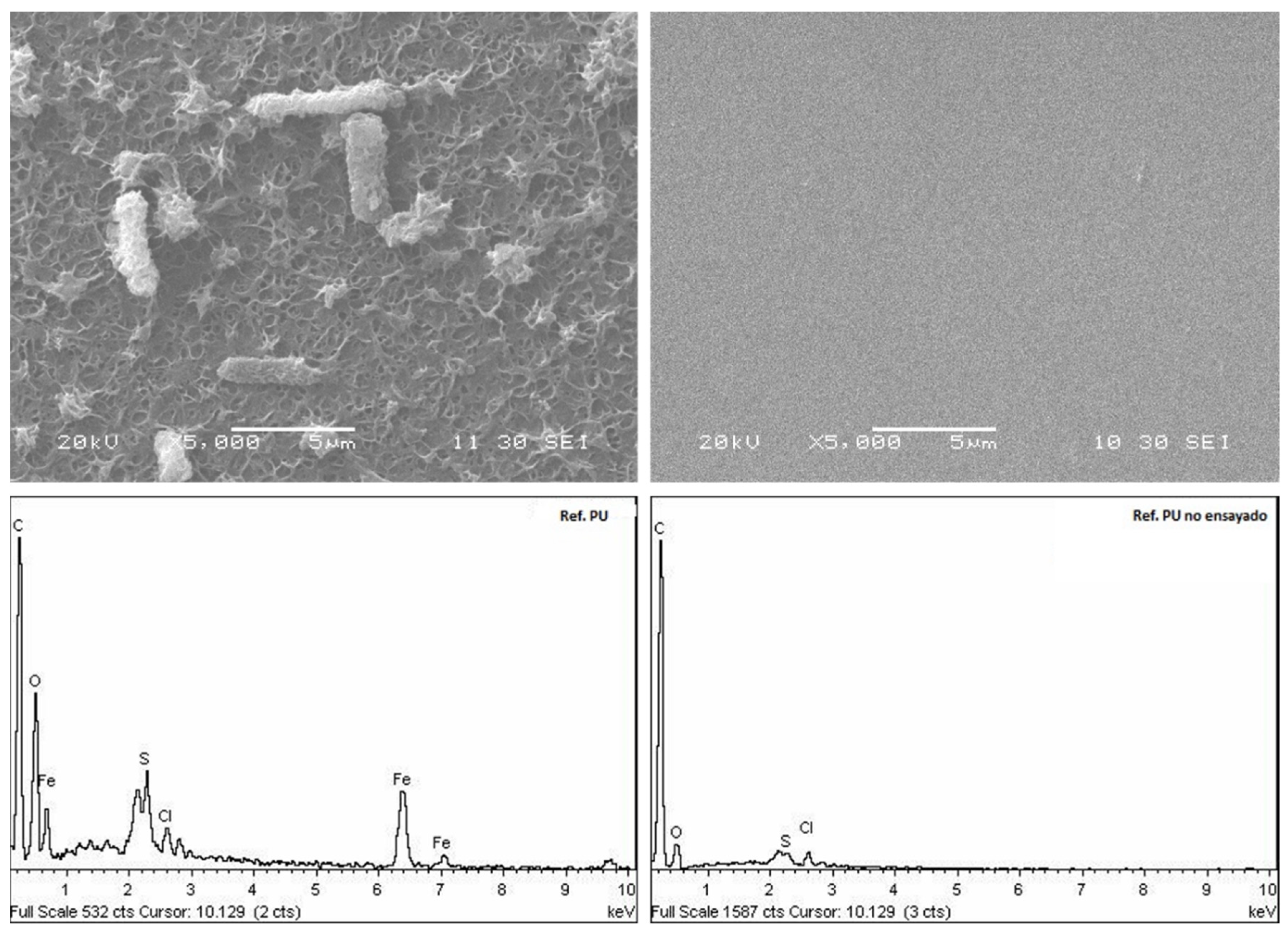
When additional coatings of TSA are applied to a steel surface, the aluminium acts as an anode, while the cathodic reaction remains the same as in the bare steel scenario. Normally, the cathodic process is neutralised by the formation of a white, passive aluminium oxide film, which protects the surface to some degree. However, chlorides present in the environment rapidly attack and erode the oxide, initiating a gradual corrosion, which may establish a galvanic current. When these passive deposits are partially removed from the surface, the porosity of TSA facilitates the migration of harmful species through the steel surface, causing corrosion.
The proposed model is summarised in Figure S12 (in Supplementary Materials). The degradation process is the same for both the sealed and unsealed samples, but the sealant delays the appearance and formation of pores due to a greater compaction of the topcoat. The model stands that steel, TSA and sealant act as three differentiable layers. With time, chloride ions and hydrogen atoms present in the medium are diffused through the organic-based sealant, corroding the TSA layer, and thus, consuming the protective layer and releasing Al cations under the epoxy-based sealant. This pitting process due to chloride could be avoided if the metal is turned into a state of perfect passivation by improving the adhesion and quality of the protective oxide film. Nevertheless, this is prevented due to the anaerobic environment and presence of a biofilm in the surface, which establishes differential aeration cells.
Having as a reference the potential pH equilibrium diagram for the aluminium–water system at room temperature, the Al3+ cation released in Medium 163 should precipitate in the form of aluminium oxide or alumina, Al2O3. Theoretical conditions of corrosion and passivation of aluminium, in the absence of other compounds with which Al forms complexes or insoluble salts, show that the main passivation layers are made of alumina that suffers a hydration process, ending up as different species of Al2O3·nH2O: n=1 böhmite or n=3 hydrargillite, the most stable form. Despite this, the EDS results of the samples conclude that the whitish precipitate generated in the TSA and TSA + sealant samples is an oxy-hydroxide precipitate of aluminium, therefore showing that there is an intermediate step in the degradation of the passive layer. The Al(OH)3 amorphous layer crystallises over the course of time to give alumina, as mentioned before, in a process known as aluminium ageing [39]. The presence of the aluminium hydroxide can be justified due to the short time period of the immersion test.
However, the Al(OH)3 formation can be explained if the mechanism of TSA degradation is in presence of SRB is driven by localised corrosion, and thereby the chemical and electrochemical conditions of the bulk environment are not maintained down the generated pit; thus, an acidic microenvironment through the surface defect is generated (Figure S13, in Supplementary Materials). As the species approach the general aqueous environment simulating artificial seawater, the pH increases as well as the nature of the formed aluminium. The proposed mechanisms comprise two well differentiated areas. The area near the pit tip mainly supports anodic reaction kinetics, while the bold surface and pit walls closer to the pit mouth primarily support cathodic reaction kinetics. Even in an anaerobic environment, because of water dissociation, the diffusion of OH anions into a pit is difficult. Anodic dissolution occurring mainly at the tip can yield high metal ion concentrations conducive to hydrolysis, thus making the microenvironment more acidic. Citing Foley’s review of the localised corrosion of aluminium [40], when the generated pit through the sealant reaches the alumina and exposes it to the electrolyte, the hydrated aluminium ion Al(H2O)63+ is rapidly formed:
Al0 → Al(H2O)63+ + 3e
which undergoes a very fast hydrolysis reaction (Ikeda et al., 2006) [41], written as:
Al(H2O)63+ ↔ Al(H2O)5(OH)2+ + H+
Aluminium hydroxo-complexes are stable below a pH = 4, which collides with the pH of the aqueous medium that is higher (pH = 8). Therefore, as both species can react with the Cl present in the media, aqueous aluminium chloride hydroxo-complexes are formed. These complexes, in permanent in the presence of chloride and form relatively stable species of Al(OH)2Cl and Al(OH)Cl2 (Equation (15)):
Al(H2O)5(OH)2+ + Cl → Al(H2O)5(OH)(Cl)+ + Cl/OH → Al(OH)2Cl or Al(OH)Cl2
These mixed aluminium aquo-complexes are pH-dependent transitions, whose products are stable at pH values between 6 and 9. Predominant corrosion products will strongly depend on the locally established pit pH. At the pit mouth, the generated basic aluminium chloride is converted slowly to amorphous Al(OH)3 by Equations (16) and (17), which, as mentioned before, is slowly transformed to the more stable oxide, Al2O3.
Al(OH)2Cl + H2O → Al(OH)3 + H+ + Cl
2Al(OH)3 (s) + H2O ↔ 2AlO(OH) + H2O ↔ Al2O3 (s) + H2O
If chlorides strongly compete with OH, displacing the latter ligand, further reactions with aluminium succeed (Equation (18)).
Al(H2O)5(OH)2+ + 3Cl → Al(H2O)3(Cl)3 ↔ AlCl3 (s) + 3H2O
The formed AlCl3 precipitate is highly hygroscopic and suffers a rapid hydrolysation to form Al(OH)3 (Equation (19)).
AlCl3 + 3H2O → Al(OH)3 (s) + 3H+ + 3Cl
Hence, this local acidification of the environment under the organic coating has two main effects. First, aluminium will be corroded actively, since the aluminium oxide is not stable at acidic environments, and secondly, a more anodic reaction site will be generated at the bottom of the pit. As long as there is a supply of electrolyte, the aluminium hydrolysis reaction will maintain itself. Thus, although the epoxy sealant generates a stronger diffusion barrier to the different cations and anions that can actually interact with aluminium species, in case the application of the sealant is not performed with exhaustive care, it could also promote a particular pit environment.
Furthermore, in this particular fully anaerobic environment, magnesium hydroxide was only observed in the EDS chemical analysis on the TSA + sealant samples, reinforcing the theory of the generation of an alternative degradation mechanism in the case of applying a sealant. Regarding the samples with an artificial defect, a larger amount of aluminium oxide was released to the surface compared to those without it. This fact remarks the protective action of the TSA despite breaking part of the passive coating. Instead of suffering iron substrate oxidation, alumina rapidly passivates, covering the defect and inhibiting further corrosion.
Once the iron substrate of the samples is reached, anodic behaviour enhances as stated in Equations (11) and (12), releasing FeS corrosion products and iron hydroxides to the surface.

3.3.2. PU Samples

The degradation mechanism of the polyurethane case must be formulated from a different perspective, as it is a totally different coating type. The mechanical properties of the polymeric materials change over time, especially when they are subjected to fatigue, as is the case of mooring lines [42]. Polyurethane, simply due to the fact of being immersed, suffers a gradual degradation of its properties due to the marine environment. Chemical changes in an anaerobic environment are specific, since there is no oxygen to promote water hydrolysis on the surface. Mechanical damage, rather than physical and chemical, is likely to determine their effective lifetime [43]. The biodegradation of PU by microorganisms has become an important issue considering the degradation mechanism in seawater, as PU could be used as carbon and/or nitrogen sources for microorganisms, providing them additional nutrients, apart from the D-lactate present in the medium.
As observed in Figure 9, an extensive biofilm layer was deposited on the PU. This layer completely stained the surface of the specimen and evidenced the proliferation of bacteria bound by EPS in the SEM images. When the PU material is significantly damaged by microbial attacks, a slow release of hazardous contaminants into the environment can occur by long-term diffusion processes. Nonetheless, research on the biodegradability of polyurethane foams under anaerobic conditions shows that there are no changes in its mechanical properties nor in the weight loss [44,45]. Nevertheless, the steel sample was protected enough during the immersion time, as can be observed in Figure S10 (in Supplementary Materials).

4. Conclusions

Along with R4S-grade steel, thermal sprayed aluminium and polyurethane coatings were evaluated as potential solutions to mitigate biocorrosion in HSLA steels. The specimens under study—steel reference (bare), TSA, TSA + Se (sealant) and PU—showed, in all cases, a biofilm on the surface exposed to the medium. This biofilm, well adhered to the surfaces of the coated and bare specimens, was mainly constituted of bacterial cells, their metabolites and, in certain cases, their corrosion products.
The studied coating systems effectively prevented, at least during the time tested, the biofilm deposition on the metal substrate, thereby delaying the bacterial-source corrosion of the steel. If the coating is corroded or damaged, thus exposing the steel to the seawater environment, the corrosion is accelerated by SRB activity, generating corrosion products enriched in iron sulphide.
It is also observed that the original surface, composed of compact ferrous oxides, delays the start and progression of corrosion with respect to the corrosion generated on a machined surface, at least in an initial phase of the degradation process. The extent of corrosion is similar between the TSA coating that incorporates a sealant (TSA + Se) and the TSA coating without sealant (TSA).
In the proposed TSA degradation mechanism, the presence and concentration of chlorides affect the performance of the TSA, since the corrosion products generated are highly dependent on the surrounding chemical species and subsequent local pH. The SRB influence promotes an even more acidic environment and a localised corrosion pathway due to a non-uniform settlement of the before-mentioned biofilm, facilitating the formation of soluble aluminium hydroxide species instead of compact and protective aluminium oxide deposits.

Supplementary Materials

The following supporting information can be downloaded at: https://www.mdpi.com/article/10.3390/cryst14030260/s1, Diagram D1. Scheme of the experimental process employed for preparation, testing and characterization of the samples; Figure S1: On top, Polyurethane sample (PU) and both PU + Defect references before the immersion test. In the bottom, TSA, Steel and TSA + Sealant references’ appearance as received and TSA + Sealant + Defect before the immersion test; Figure S2: Certificate of Origin and Analysis of DSMZ 1926 Desulfovibrio Desulfuricans culture; Figure S3: Marine Desulfovibrio (Postgate) Medium specifications; Figure S4: Appearance of the beakers once the SRB are inoculated, left, (t = 0 days) and after 4 days of immersion test, right; Figure S5: Aspect of beaker 3 references prior to dehydration and biofilm fixation process; Figure S6: Steel reference appearance after immersion test, both original and machined sides; Figure S7: TSA reference appearance after immersion test, both original and machined sides; Figure S8: TSA + Se reference appearance after immersion test, both original and machined sides; Figure S9: Polyurethane reference appearance after immersion test, both original and machined sides; Figure S10: Polyurethane reference appearance after immersion test, with PU topcoat removal, unveiling the intact Steel substrate; Figure S11: Micrography at ×150 magnification showing attached biofilm in the scribe edge of PU sample; Figure S12: Mechanism of biofilm formation related to SRB activity and concentration; Figure S13: Most stable species as function of the established pH between the pit tip and the pit mouth and bold surface; Table S1: Summary table of semi quantitative EDS chemical analysis of tested samples.

Author Contributions

Conceptualization, J.-B.J. and E.R.; methodology, V.M. and J.-B.J.; validation J.-B.J. and V.M.; formal analysis, E.R.; investigation I.S.-P. and V.M.; resources, J.-B.J. and E.R.; data curation: I.S.-P., E.A. and V.M. writing-original draft preparation, I.S.-P.; writing—review and editing, I.S.-P., V.M., E.R. and E.A.; visualization, E.A.; supervision, V.M.; project administration, J.-B.J. and E.R.; funding acquisition, J.-B.J. and E.R. All authors have read and agreed to the published version of the manuscript.

Funding

This research received no external funding.

Data Availability Statement

The original contributions presented in the study are included in the article/Supplementary Material, further inquiries can be directed to the corresponding author.

Acknowledgments

The authors would like to thank Noelia Alvarez and Jaione Lorenzo for their support and advice in the laboratory and Pablo Benguria Uribe for proof reading and shared know-how.

Conflicts of Interest

Authors Iñigo Santos-Pereda, Virginia Madina and Jean-Baptiste Jorcin was employed by the company TECNALIA, Basque Research and Technology Alliance (BRTA). The remaining authors declare that the research was conducted in the absence of any commercial or financial relationships that could be construed as a potential conflict of interest.

References

  1. Abdolahi, A.; Hamzah, E.; Ibrahim, Z.; Hashim, S. Application of environmentally-friendly coatings toward inhibiting the microbially influenced corrosion (mic) of steel: A review. Polym. Rev. 2014, 54, 702–745. [Google Scholar] [CrossRef]
  2. Alia, C.; Biezma, M.V.; Pinilla, P.; Arenas, J.M.; Suárez, J.C. Degradation in seawater of structural adhesives for hybrid fibre-metal laminated materials. Adv. Mater. Sci. Eng. 2013, 2013, 869075. [Google Scholar] [CrossRef]
  3. Korb, L.J.; Olson, D.L. ASM Metals Handbook Volume 13—Corrosion, 4th ed.ASM International: Novelty, Ohio, USA, 1992. [Google Scholar]
  4. Barron, A.R. The interaction of carboxylic acids with aluminium oxides: Journeying from a basic understanding of alumina nanoparticles to water treatment for industrial and humanitarian applications. Dalton Trans. 2014, 43, 8127–8143. [Google Scholar] [CrossRef]
  5. Bonner, P.E.; Stanners, J.F. Protection of steel by metal spraying: A review. Br. Corros. J. 1966, 1, 339–343. [Google Scholar] [CrossRef]
  6. Chaliampalias, D.; Vourlias, G.; Pavlidou, E.; Stergioudis, G.; Skolianos, S.; Chrissafis, K. High temperature oxidation and corrosion in marine environments of thermal spray deposited coatings. Appl. Surf. Sci. 2008, 255, 3104–3111. [Google Scholar] [CrossRef]
  7. Chavant, P.; Gaillard-Martinie, B.; Talon, R.; Hébraud, M.; Bernardi, T. A new device for rapid evaluation of biofilm formation potential by bacteria. J. Microbiol. Methods 2007, 68, 605–612. [Google Scholar] [CrossRef] [PubMed]
  8. Cord-Ruwisch, R. Microbially Influenced Corrosion of STEEL. In Environmental Microbe-Metal Interactions; Lovley, D.R., Ed.; ASM Press: Washington DC, USA, 2000; pp. 159–173. [Google Scholar] [CrossRef]
  9. Dall’Agnol, L.T.; Moura, J.J.G. Sulphate-reducing bacteria (SRB) and biocorrosion. In Understanding Biocorrosion: Fundamentals and Applications; Woodhead Publishing Limited: Sawston, UK, 2014; pp. 77–106. [Google Scholar] [CrossRef]
  10. Davies, P.; Evrard, G. Accelerated ageing of polyurethanes for marine applications. Polym. Degrad. Stab. 2007, 92, 1455–1464. [Google Scholar] [CrossRef]
  11. Davis, J.R. (Ed.) Handbook of Thermal Spray Technology, 1st ed.; ASM International: Almere, The Netherlands, 2004. [Google Scholar]
  12. Edyvean, R.; Maines, A.; Hutchinson, C.; Silk, N.; Evans, L. Interactions between cathodic protection and bacterial settlement on steel in seawater. Int. Biodeterior. Biodegrad. 1992, 29, 251–271. [Google Scholar] [CrossRef]
  13. Enning, D.; Garrelfs, J. Corrosion of Iron by Sulfate-Reducing Bacteria: New Views of an Old Problem. Appl. Environ. Microbiol. 2014, 80, 1226–1236. [Google Scholar] [CrossRef] [PubMed]
  14. Fernandez de Romero, M. The mechanism of SRB action in MIC based on sulfide corrosion and iron sulfide corrosion products. In Proceedings of the NACE—International Corrosion Conference Series, Houston, TX, USA, 3–7 April 2005; pp. 1–30. [Google Scholar]
  15. Foley, R.T.; Nguyen, T.H. The Chemical Nature of Aluminum Corrosion: V. Energy Transfer in Aluminum Dissolution. J. Electrochem. Soc. 1982, 129, 464–467. [Google Scholar] [CrossRef]
  16. Geesey, G.G.; Mittleman, M.W.; Iwaoka, T.; Griffiths, P.R. Role of bacterial exopolymers in the deterioration of metallic copper surfaces. Mater. Perform. 1986, 25, 37–40. [Google Scholar]
  17. Gittens, J.E.; Smith, T.J.; Suleiman, R.; Akid, R. Current and emerging environmentally-friendly systems for fouling control in the marine environment. Biotechnol. Adv. 2013, 31, 1738–1753. [Google Scholar] [CrossRef]
  18. Gougoulidis, G.; Michelis, A. Current and Future Trends in Marine Antifouling Coatings and the Study of Energy Efficiency Benefits for a Naval Fleet. In Environment & Energy in Ships; Environment & Energy in Ships EEinS 2015; ASHRAE: Athens, Greece, 2015. [Google Scholar]
  19. Gurrappa, I. Cathodic protection of cooling water systems and selection of appropriate materials. J. Am. Acad. Dermatol. 2005, 166, 256–267. [Google Scholar] [CrossRef]
  20. Hamilton, W.A. Sulphate-reducing bacteria and anaerobic corrosion. Annu. Rev. Microbiol. 1985, 39, 195–217. [Google Scholar] [CrossRef]
  21. Ikeda, T.; Hirata, M.; Kimura, T. Hydrolysis of Al3+ from constrained molecular dynamics. J. Chem. Phys. 2006, 124, 74503. [Google Scholar] [CrossRef] [PubMed]
  22. Javaherdashti, R. Microbiologically Influenced Corrosion, 2nd ed.; Springer International Publishing: Perth, Australia, 2017. [Google Scholar]
  23. Kakooei, S.; Ismail, M.C.; Ariwahjoedi, B. Mechanisms of Microbiologically Influenced Corrosion: A Review. World Appl. Sci. J. 2012, 17, 524–531. [Google Scholar]
  24. Lee, H.-S.; Park, J.-H.; Singh, J.K.; Ismail, M.A. Protection of reinforced concrete structures of waste water treatment reservoirs with stainless steel coating using arc thermal spraying technique in acidified water. Materials 2016, 9, 753. [Google Scholar] [CrossRef] [PubMed]
  25. Lee, H.-S.; Singh, J.K.; Ismail, M.A. An effective and novel pore sealing agent to enhance the corrosion resistance performance of Al coating in artificial ocean water. Sci. Rep. 2017, 7, 41935. [Google Scholar] [CrossRef] [PubMed]
  26. Little, B.J.; Lee, J.S. Microbiologically Influenced Corrosion, 1st ed.; Wiley-Interscience: Hoboken, NJ, USA, 2007. [Google Scholar]
  27. Norsok Standard M-501; Surface Preparation and Protective Coating. Norsk Sokkels Konkuranseposisjon: Lysaker, Norway, 2012.
  28. Loto, C.A. Microbiological corrosion: Mechanism, control and impact—A review. Int. J. Adv. Manuf. Technol. 2017, 92, 4241–4252. [Google Scholar] [CrossRef]
  29. Madina, V. Corrosión Bacteriana en Condiciones Representativas de un Almacén Geológico Profundo. Ph.D. Thesis, Universidad del País Vasco, Leioa, Spain, 2014. [Google Scholar]
  30. Maxwell, S.; Devine, C.; Rooney, F. Monitoring and Control of Bacterial Biofilms in Oilfield Water Handling Systems. Presented at the CORROSION 2004, New Orleans, LA, USA, 28 March–1 April 2004. NACE-04752. [Google Scholar]
  31. Melchers, R.E.; Moan, T.; Gao, Z. Corrosion of working chains continuously immersed in seawater. J. Mar. Sci. Technol. 2007, 12, 102–110. [Google Scholar] [CrossRef]
  32. Momber, A.W.; Marquardt, T. Protective coatings for offshore wind energy devices (OWEAs): A review. J. Coatings Technol. Res. 2018, 15, 13–40. [Google Scholar] [CrossRef]
  33. Pourbaix, M.; Franklin, J.A. Atlas of Electrochemical Equilibria in Aqueous Solutions; Pergamon Press: Oxford, UK, 1974. [Google Scholar]
  34. Reusch, W. Carboxylic Acids [WWW Document]. Michigan State Univ. 2013. Available online: https://www2.chemistry.msu.edu/faculty/reusch/virttxtjml/crbacid1.htm (accessed on 1 February 2024).
  35. Santegoeds, C.M.; Ferdelman, T.G.; Muyzer, G.; de Beer, D. Structural and Functional Dynamics of Sulfate-Reducing Populations in Bacterial Biofilms. Appl. Environ. Microbiol. 1998, 64, 3731–3739. [Google Scholar] [CrossRef] [PubMed]
  36. Stanzione, M.; Russo, V.; Oliviero, M.; Verdolotti, L.; Sorrentino, A.; Di Serio, M.; Tesser, R.; Iannace, S.; Lavorgna, M. Characterization of sustainable polyhydroxyls, produced from bio-based feedstock, and polyurethane and copolymer urethane-amide foams. Data Brief 2018, 21, 269–275. [Google Scholar] [CrossRef] [PubMed]
  37. Tandogan, N.; Abadian, P.N.; Huo, B.; Goluch, E.D. Antimicrobial coatings and modifications on medical devices. In Antimicrobial Coatings and Modifications on Medical Devices; Zhang, Z., Wagner, V.E., Eds.; Springer International Publishing: Berlin/Heidelberg, Germany, 2017; pp. 1–273. [Google Scholar] [CrossRef]
  38. Trif, L.; Shaban, A.; Telegdi, J. Electrochemical and surface analytical techniques applied to microbiologically influenced corrosion investigation. Corros. Rev. 2018, 36, 349–363. [Google Scholar] [CrossRef]
  39. Urgun-Demirtas, M.; Singh, D.; Pagilla, K. Laboratory investigation of biodegradability of a polyurethane foam under anaerobic conditions. Polym. Degrad. Stab. 2007, 92, 1599–1610. [Google Scholar] [CrossRef]
  40. Vester, F.; Ingvorsen, K. Improved MPN method to detect sulfate-reducing bacteria with natural media and a Radiotracer. Appl. Environ. Microbiol. 1998, 64, 1700–1707. [Google Scholar] [CrossRef] [PubMed]
  41. Videla, H.A.; Herrera, L.K. Microbiologically influenced corrosion: Looking to the future. Int. Microbiol. 2005, 8, 169–180. [Google Scholar]
  42. Von Wolzogen Kühr, C.A.H.; van der Vlugt, L.S. Graphitization of Cast Iron as an Electro-Biochemical process in anaerobic soils. Water 1934, 18, 147–165. [Google Scholar]
  43. Wood, R.J.K. Tribo-corrosion of coatings: A review. J. Phys. D Appl. Phys. 2007, 40, 5502–5521. [Google Scholar] [CrossRef]
  44. Xu, W.; Ma, C.; Ma, J.; Gan, T.; Zhang, G. Marine Biofouling Resistance of Polyurethane with Biodegradation and Hydrolyzation. ACS Appl. Mater. Interfaces 2014, 6, 4017–4024. [Google Scholar] [CrossRef]
  45. Yebra, D.M.; Kiil, S.; Dam-Johansen, K. Antifouling technology—Past, present and future steps towards efficient and environmentally friendly antifouling coatings. Prog. Org. Coatings 2004, 50, 75–104. [Google Scholar] [CrossRef]
Figure 1. Micrography at 1000× magnification showing biofilm attached to the original surface of the steel sample, with the associated EDS spectra.
Crystals 14 00260 g001
Figure 2. Micrography at 1000× magnification showing biofilm attached to the machined surface of the steel sample, as well as grinding marks.
Crystals 14 00260 g002
Figure 3. Micrography at 500× magnification showing generated pitting on the machined surface of the steel sample, with the associated EDS spectrum.
Crystals 14 00260 g003
Figure 4. Micrography at 500× magnification showing biofilm attached to the original surface of the TSA sample, with the associated EDS spectra for both yellow and whitish areas.
Crystals 14 00260 g004
Figure 5. Micrography at 1000× magnification showing biofilm attached to the original surface of the TSA + Se sample, with the associated EDS spectra for both grey and whitish areas.
Crystals 14 00260 g005
Figure 6. Micrography at 5000× magnification showing clearly attached biofilm on the original surface of the PU sample, with the associated EDS spectrum.
Crystals 14 00260 g006
Figure 7. Micrographics at 5000× magnification and associated EDS spectra showing noticeable differences between the tested PU sample (left) and untested PU sample (right).
Crystals 14 00260 g007
Figure 8. Proposed interaction between bacterial colonies and metal or organic surfaces for (a) steel, (b) TSA, (c) TSA + Se, and (d) PU systems.
Crystals 14 00260 g008
Figure 9. Proposed corrosion mechanism of TSA and TSA + Se samples. In this case, the degradation process is the same; only the sealant delays the appearance and formation of the pores due to greater compaction of the topcoat.
Crystals 14 00260 g009
Table 1. Coating systems under study.
SystemReferenceDimensions (mm)Specimen Quantity
1Bare steel100 × 504
2Steel + TSA100 × 504
3Steel + TSA + sealant100 × 506
4Steel + TSA + sealant and superficial defect100 × 502
5Steel + polyurethane *150 × 754
6Steel + polyurethane * and superficial defect150 × 752
* 750 microns of polyurethane coating.
Table 2. Sample number, characteristics and SRB concentration in each beaker at the start and end of the immersion tests.
BeakerSample[SRB] cfu/mL
(t = 0 days)
[SRB] cfu/mL
(t = 29 days)
Analysis after Immersion
1Steel1.2 × 1052.90 × 106Visual inspection
PU + DefVisual inspection +
SEM/EDS
2PU + Def1.2 × 1051.41 × 106Visual inspection
TSAVisual inspection
TSA + Se + DefNone
3Steel1.2 × 1053.91 × 106Visual inspection + SEM/EDS
TSAVisual inspection + SEM/EDS
TSA + SeVisual inspection + SEM/EDS
Control beakerNo samples1.2 × 1051.41 × 106-
Note: Def: punctual defect. Se: sealant.
Disclaimer/Publisher’s Note: The statements, opinions and data contained in all publications are solely those of the individual author(s) and contributor(s) and not of MDPI and/or the editor(s). MDPI and/or the editor(s) disclaim responsibility for any injury to people or property resulting from any ideas, methods, instructions or products referred to in the content.

