Article

Investigating the Influence of Three Different Atmospheric Conditions during the Synthesis Process of NMC811 Cathode Material

1
Department of Chemistry and NIS-INSTM, University of Turin, 10125 Turin, Italy
2
C.R.F. SCpA, Strada Torino 50, 10043 Orbassano, Italy
3
Comau S.p.A., Via Rivalta 49, 10095 Grugliasco, Italy
4
CIRCC, Via Celso Ulpiani 27, 70126 Bari, Italy
5
Skolkovo Institute of Science and Technology Bolshoy Boulevard 30, Bldg. 1, 121205 Moscow, Russia
*
Authors to whom correspondence should be addressed.
Crystals 2024, 14(2), 137; https://doi.org/10.3390/cryst14020137
Submission received: 24 December 2023 / Revised: 24 January 2024 / Accepted: 26 January 2024 / Published: 29 January 2024

Abstract

:
Lithium-ion batteries (LIBs) are fundamental for the energetic transition necessary to contrast climate change. The characteristics of cathode active materials (CAMs) strongly influence the cell performance, so improved CAMs need to be developed. Currently, Li(Ni0.8Mn0.1Co0.1)O2 (NMC811) is state-of-the-art among the cathodic active materials. The aim of this work is the optimization of the procedure to produce NMC811: two different syntheses were investigated, the co-precipitation and the self-combustion methods. For a better understanding of the synthesis conditions, three different types of atmospheres were tested during the calcination phase: air (partially oxidizing), oxygen (totally oxidizing), and nitrogen (non-oxidizing). The synthesized oxides were characterized by X-ray Powder Diffraction (XRPD), Scanning Electron Microscopy (SEM), Energy Dispersive X-ray (EDX), Inductively Coupled Plasma (ICP), and Particle Size Distribution (PSD). The most promising materials were tested in a half-cell set up to verify the electrochemical performances. The procedure followed during this study is depicted in the graphical abstract. The oxidizing atmospheric conditions turned out to be the most appropriate to produce NMC811 with good electrochemical properties.

1. Introduction

The capabilities of LIBs extend far beyond their conventional applications in smartphones or laptops. Their potential has garnered growing attention in diverse fields, including Electric Vehicles (EVs), Hybrid Electric Vehicles (HEVs), and grid applications [1]. This stems from their remarkable attributes, such as a high energy density facilitated by elevated cell voltages (~4 V), superior cycle performance, and exceptional power density, all of which surpass those of alternative rechargeable battery technologies [2]. To increase the energy storage capacity of LIBs, transition metal (TM) oxides have been proposed as a promising positive electrode material [3]. The most popular cathode material is nickel manganese cobalt oxide (NMC), a layered transition metal oxide with composition LiNixMnyCo1−x−yO2 and rhombohedral R-3m crystallographic structure. Different materials can be prepared using different ratios (x- and y-values) among Ni, Co, and Mn. The most popular are NMC111 [4], NMC532 [5], NMC622 [6], and NMC811 [7]. The use of nickel-rich compositions as the positive electrode in batteries offers numerous advantages: one of the key benefits is the high energy storage capacity compared to other TMs, allowing for a high energy density in the battery [7]. On the other hand, the thermal stability of the structure decreases with the increasing of the nickel content [8].
As far as synthesis of NMC material is concerned, different approaches are available including Spray Pyrolysis, Sol-Gel, co-precipitation (CPT), Solid-State, self-combustion (SCS), and others [9].
The CPT technique has gained popularity in synthesizing NMC due to its straightforward procedure, capacity to control morphology, and capability of generating a highly homogeneous mixture at the atomic level. Moreover, this synthetic process is currently used for industrial production, thanks to the possibility of being scaled up [9].
On the other hand, the SCS synthesis method is a simple technique, it is rapid, and it does not need expensive equipment. It has a minimal external energy requirement, which translates into low carbon emissions, making it eco-friendly and sustainable [9,10].
The first step of the CPT technique consists of the precipitation of a hydroxide precursor: Li(Ni0.8Mn0.1Co0.1)(OH)2, that is prepared adding a chelating agent (NH4OH) and a precipitation agent (NaOH) to the transition metals solution. The role of pH in hydroxide precipitation holds significant importance as it affects the chemical properties of the various species formed in the solution. Moreover, the hydroxide ion acts as the principal precipitation agent, and an increase in pH levels results in a higher driving force for nucleation and growth [11]. However, the pH level of a solution has a significant impact on hydroxide precipitation, which affects the size and shape of the particles. Formation of the fine particles is usually associated with a high supersaturation and fast precipitation rates. Achieving a high tap density is crucial as it can enhance the properties and performance of materials. In particular, the tap density of electrode materials significantly affects their capacity and cycling stability. Therefore, obtaining spherical particles with smooth surfaces through synthesis at optimum pH values can be advantageous in improving the overall quality and effectiveness of the final product [12].
Ammonia works as a chelating agent, and it is able to regulate the growth of precipitate particles [13], according to Equations (1) and (2):
M2+ + xNH4OH(aq.)→M(NH3)n 2+(aq.) + xH2O
M(NH3)n 2+(aq.) + yOH → M(OH)2 (s) + nNH3
According to the suggested mechanism, ammonia first creates complexes with TM ions in the solution. These complexes then undergo a gradual reaction with hydroxide ions, leading to the formation of precipitates. The final particles obtained from this process are spherical and composed of primary particles. Nevertheless, Ying et al. [14] discovered that increasing the concentration of ammonia resulted in more spherical particles with a narrower size distribution that resulted in a higher tap density for the particles.
During the synthesis of NMC materials, the final step involves a calcination process conducted at elevated temperatures to achieve a micrometric crystalline structure. It is crucial to ensure that the temperature does not exceed 1000 °C to avoid any potential lithium volatilization [9].
For the purposes of this investigation, two synthesis techniques (i.e., CPT and SCS) were selected. The processes adopted in this work are reported in Figure 1. The main goal is to determine the influence of a partially oxidizing atmosphere, a totally oxidizing atmosphere, and non-oxidizing atmosphere on the properties of the synthesized NMC811. So, during the calcination process, three different atmospheric conditions (air, oxygen, and nitrogen) were used.

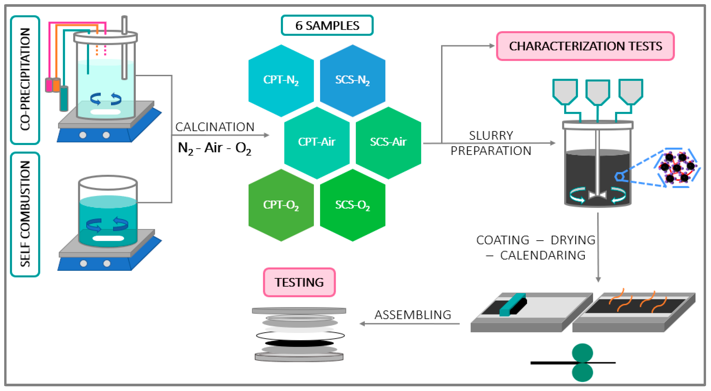
2. Materials and Methods

2.1. SCS Approach

In this method, lithium nitrate and TMs (transition metals) nitrate were the starting materials, sucrose was needed as ignition fuel, and deionized (DI) water was the solvent. Ni(NO3)2·6H2O 0.12M, Mn(NO3)2·4H2O 0.015 M, and Co(NO3)2·6H2O 0.015 M were added in a stirring beaker with DI water at room temperature, followed by the addition of LiNO3·4H2O 0.30 M and sucrose 0.15 M. The ratio between Li and TMs was fixed to 2:1 to compensate for the loss of lithium during the combustion step. The solution was stirred for three hours, then the temperature was increased to 70 °C to facilitate water evaporation. After approximately 12 h, most of the water evaporated, leaving a syrup-like solution with a high viscosity. The material was then exposed to a furnace at 110 °C for 2 h, producing a cake-like mass. To transform the resulting sponge-like structure into a powdery form, the temperature was raised up to 320 °C for 30 min. In this step, because of the self-ignition of reactants, an intense exothermic reaction [15] led to the formation of porous and powdery materials [10].

2.2. CPT Approach

In this approach, TM sulfates and lithium hydroxide were the starting materials. A stoichiometric quantity of TM sulfates (8:1:1) was selected and mixed with DI water to create a solution composed of NiSO4·6H2O 1.6 M, MnSO4·H2O 0.2 M, and CoSO4·7H2O 0.2 M [16]. An alkaline solution was prepared mixing 180 mL of DI water, 18 mL of NH4OH 1.5 M, and 0.333 mL of NaOH 4 M in a three-necked round flask. The solution was kept in an inert atmosphere (N2) in continuous stirring and at a constant temperature of 55 °C. The pH was periodically checked and adjusted by adding NaOH drop by drop to be maintained at 11.5 [17]. Once the temperature and pH were stabilized, the TMs solution was added to the flask. Then, 30 mL of each NaOH 4 M and NH4OH 1.5 M was slowly poured. During the stirring process overnight, the precursor Li(Ni0.8Mn0.1Co0.1)(OH)2 started to precipitate. The solid product was separated, washed with DI water, and dried overnight in a vacuum furnace at 110 °C. Finally, before the calcination step, Li(Ni0.8Mn0.1Co0.1)(OH)2 was mixed with Li(OH) H2O at a ratio of 1:1.15 M (precursor: Li source) under the Ar atmosphere in a glove box. Also in this case, a lithium excess was used to compensate for the lithium loss during the synthesis process.

2.3. Calcination

The final stage in the synthesis of NMC811 consisted of a two-step calcination. During the process, a specific gas was flushed inside the tube furnace. Three different atmospheric conditions were tested: air, pure oxygen, and pure nitrogen with 0.2 L/min flow rate for all the batches.
Initially, samples were heated up to 500 °C for 5 h to melt the lithium source by using a tube furnace to ensure a good distribution within the precursor [9]. The first annealing step can assist in eliminating any possible organic residual or other impurities present in the precursor, thus improving the overall purity of the final cathode material [10].
Subsequently, in the second step, batches were cooled back down to room temperature and finely ground. The resulting samples were then subjected to a further calcination at an elevated temperature (900 °C for 16 h) to ensure the uniform arrangement of lithium and TM atoms into a layered structure [18].
Finally, all batches were finely grounded using a pestle and mortar. The quality of the cathode materials was influenced by calcination parameters like sintering time, temperature, and atmospheric conditions.
From now on, the batches which were synthesized through the CPT method and calcinated under air, oxygen, and nitrogen flow are named CPT-Air, CPT-O2, and CPT-N2, respectively. The batches which were synthesized using the SCS approach and calcinated under the same atmospheric conditions are named SCS-Air, SCS-O2, and SCS-N2. A commercial NMC811 (MTI Corp., Richmond, VA, USA) was used for comparison.

2.4. Slurry Preparation—Coating—Calendaring—Drying

To prepare cathode electrodes, the synthesized NMC811 samples were used to produce suspensions (slurries) that were deposited on an aluminum current collector. The tested slurries were composed of a ratio of 90:5:5 in weight of active material (NMC811), polyvinylidene-difluoride (PVdF) as binder, and carbon black 65 (CB65) as conductive agent. The presence of carbon black was necessary because it enhanced the electric conductivity of the electrode [19]. The selection of PVdF stemmed from its high electrochemical stability, electrolyte wettability, and satisfactory interfacial adhesion between electrode laminates and current collector. PVdF was previously dissolved in NMP (N-Methyl-2-pyrrolidone), forming a solution of 8%wt. NMP was also used as solvent for the slurry [20]. For each batch, 0.6 g of NMC811 was combined with 0.033 g of CB65 and 0.416 g of PVdF and mixed with 300–500 µL of NMP in an Eppendorf tube. Two magnetics balls were added in the tube, and it was placed inside a ball-milling device to enhance the homogeneity of the slurry: the milling process was performed at a frequency of 15 Hz for a period of 30 min. Following that, the prepared slurries were coated on an aluminum foil with a thickness of 200 µm, using blade-coating equipment. Afterward, the electrodes were placed in an oven set at a temperature of 55 °C for 90 min. After this step, each electrode sheet was cut to fit coin cell (16 mm diameter) and then subjected to the calendaring process, for which a manual laboratory cold press was utilized, applying a pressure of 8 tons on the electrodes. The aim of the calendaring process was to enhance the energy density and electronic conductivity of the electrode, while also determining its final porous microstructure [21]. Finally, the electrodes were dried at 110 °C under vacuum overnight.

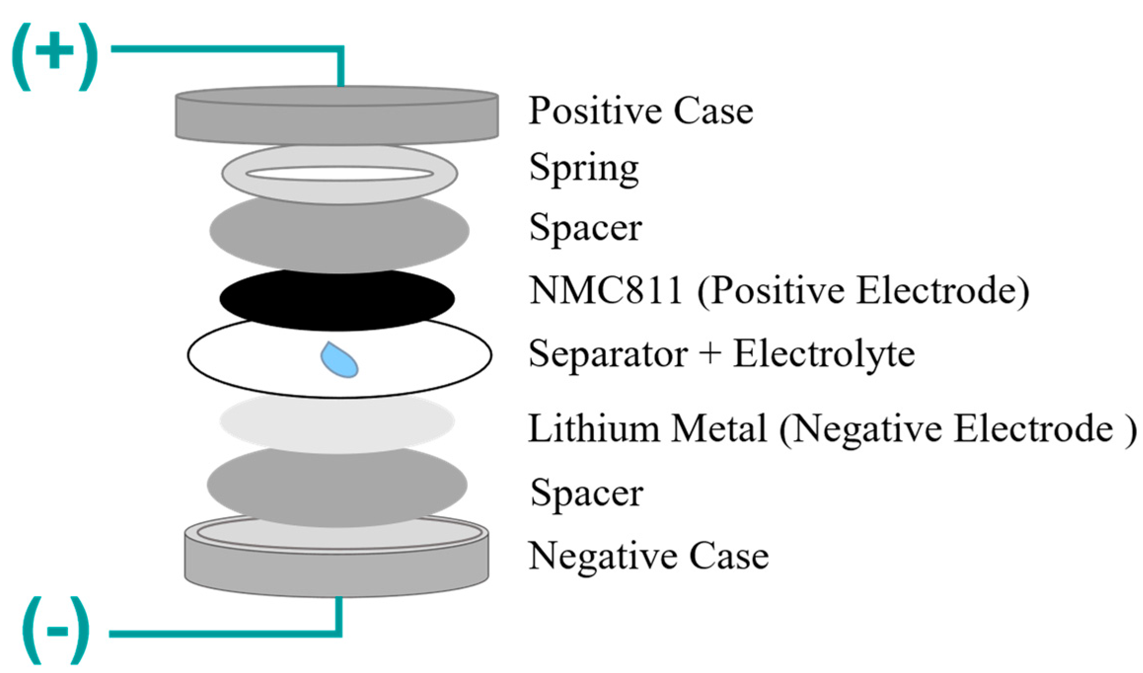
2.5. Assembling Process

The assembly of half-cells was carried out in a glove box under an argon atmosphere. Lithium metal was used as the anode and cut with the same diameter of cathode electrodes (16 mm). The separator employed was a polypropylene disc with the diameter of 19 mm and thickness of 16 ± 1.5 µm. The electrolyte composition was 1M LiPF6 in EC: EMC (ethylene carbonate: ethyl methyl carbonate) 50:50 ratio. At first, the separator, the lithium, and cathode were soaked by 25 µL of electrolyte. Then, the assembling process of the coin cells took place with the following steps: negative cover, spacer, lithium electrode, separator with 75 µL of electrolyte, cathode electrode, spacer, spring, and positive cover, which closed all the package. The coin cells were sealed with a specific tool under a pressure of 1000 kg/cm2. In Figure 2, the components of a coin cell within the assembling process are shown.

2.6. XRD

The structural analysis of prepared samples was performed using X-ray Diffraction (XRD) with a INI FLEX 600 (Rigaku Corp., Tokyo, Japan) with a Bragg–Brentano flat geometry, using Cu-Kα radiation (λ = 1.5406 Å; 40 kV, 15 mA). The analyses were performed within 15° < 2θ < 90° with a scanning speed of 1.0 °/min and step size of 0.020°. The recognition of crystal phases was performed using PDXL, integrated X-ray Powder Diffraction software by Rigaku, and the PDF-4+ 2023 database [22]. Rietveld refinement was obtained using Material Analysis Using Diffraction (MAUD) software version 2.9993 [23].
The following sequence was applied for the refinement of parameters: (1) scale factor, (2) background parameters, (3) lattice parameters, (4) crystallite size, (5) micro strain, and (6) atomic site occupancies. For the air- and oxygen-treated samples, the cation mixing was estimated using Rietveld simulation as follows. The 3a (0,0,0) site of the NMC structure was populated by Li and Ni, whereas Li, Ni, Mn, and Co were placed at the 3b (0,0,1/2) site. The occupancies were refined according to the materials stoichiometry supported by ICP-AES, therefore, applying the following constraints:
OLi3a + OLi3b = 1
ONi3a + ONi3b = 0.8
where O indicates the occupancies of different sites. The refinement was also used to determine the weight fraction of the different phases present in the sample.

2.7. SEM and EDS

The morphology of prepared samples was observed using Scanning Electron Microscopy (SEM). The accelerating electron high voltage was set to 20 kV, and the secondary electron detector was used. To compare sizes and shapes of particles, the magnification was set to 5.00 Kx. Energy Dispersive X-ray (EDS) maps were obtained for all the elements except lithium, due to the low energy of lithium characteristic X-ray emission.

2.8. ICP

Inductively Coupled Plasma (ICP) analysis was performed to investigate the composition of the prepared materials. For measurements, 0.25 g of powder was weighed using an analytical balance (0.0001 g), transferred to a volumetric flask (250 mL), and etched using hot aqua regia on a hot plate (HCl, HNO3 with the ratio of 3:1). Once brought to volume, an aliquot was subsequently diluted (5–10 times depending on the concentrations of the elements). All the metals were quantified using a method with 3 calibrated solutions at certified concentration (0 ppm, 25 ppm, and 50 ppm), and the results were expressed in % [m/m].

2.9. PSD

A Particle Size Distribution (PSD) analysis was carried out with an Anton Paar PSA 1090 LD (Anton Paar Australia Pty. Ltd., North Ryde, NSW, Australia), which is based on static light laser diffraction technology.

2.10. Cycling and C-Rate Performance

Electrochemical performances of the cathodes were evaluated in half-cell versus a Li metal anode using a coin cell configuration and a CTS-LAB battery testing station (BaSyTec, Asselfingen, Deutschland). The temperature was set to 25 °C and controlled using an FALC climatic chamber. The cycling test consisted of three charge–discharge cycles at 0.1 C-rate, followed by 50 charge–discharge cycles at 0.5 C-rate. The C-rate test consisted of 21 charge–discharge cycles with the charge at 0.1 C-rate and the discharge at different C-rate: 0.1 C, 0.2 C, 0.5 C, 1.0 C, 2.0 C, and 5.0 C (three cycles for each one).

3. Results and Discussions
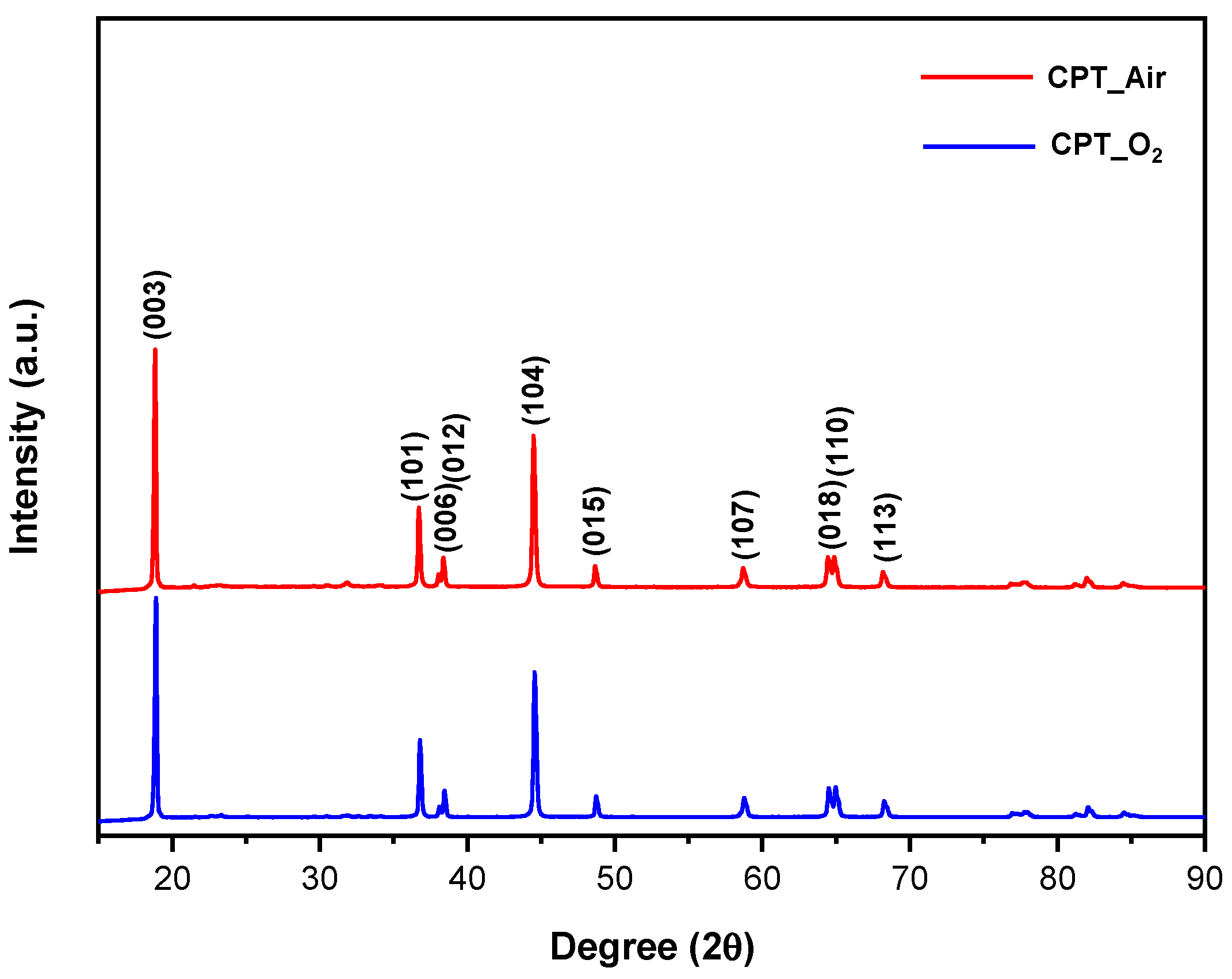
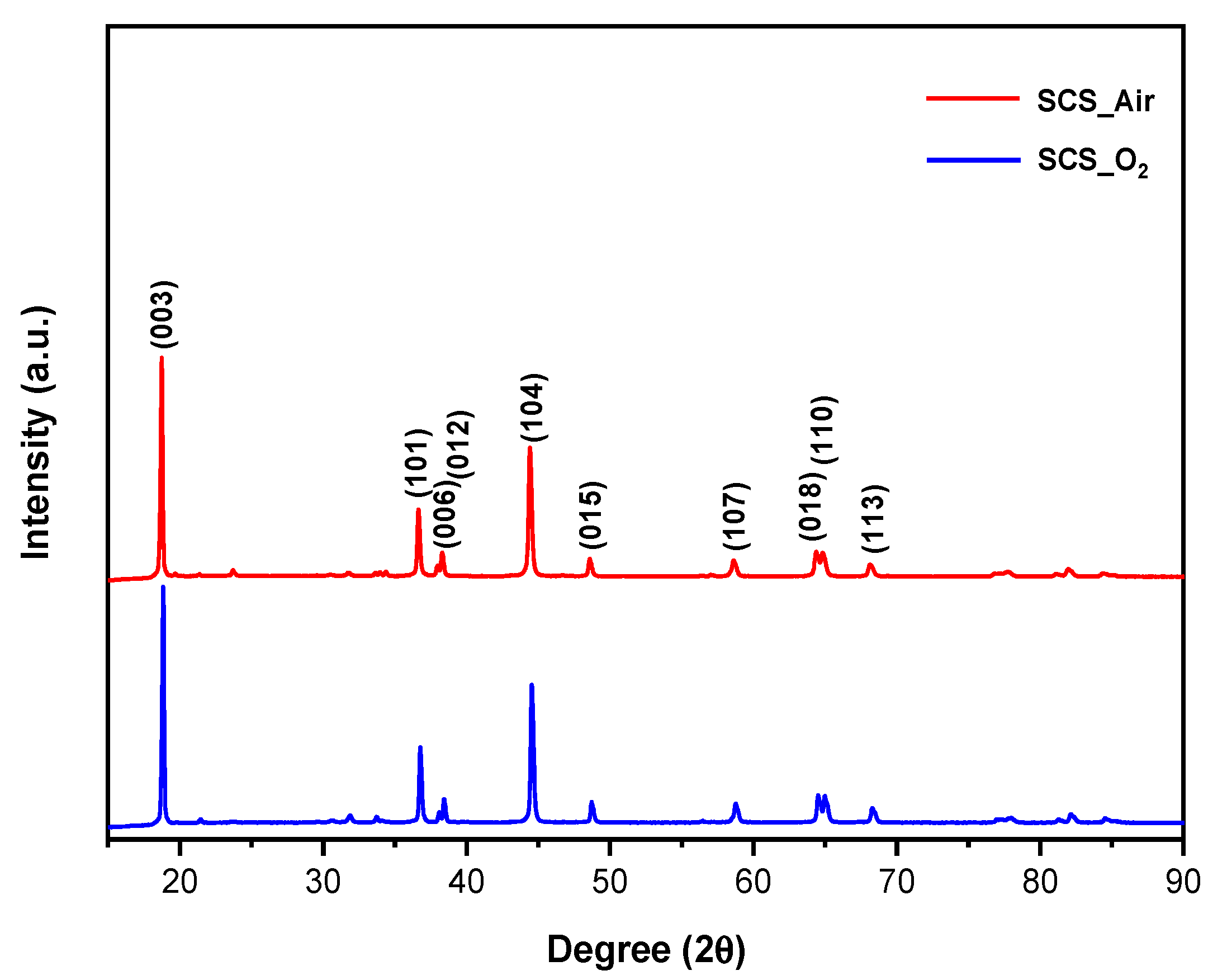
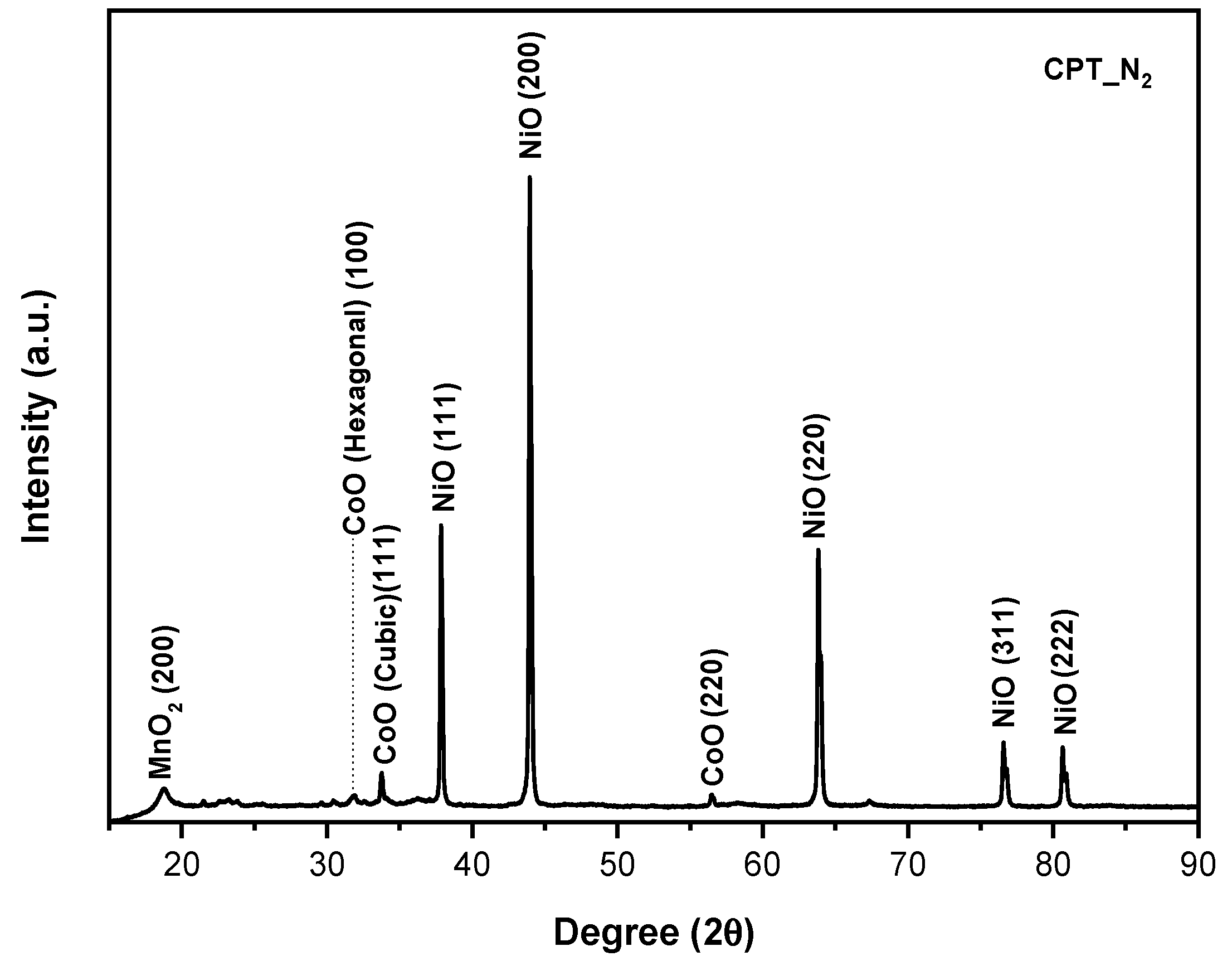
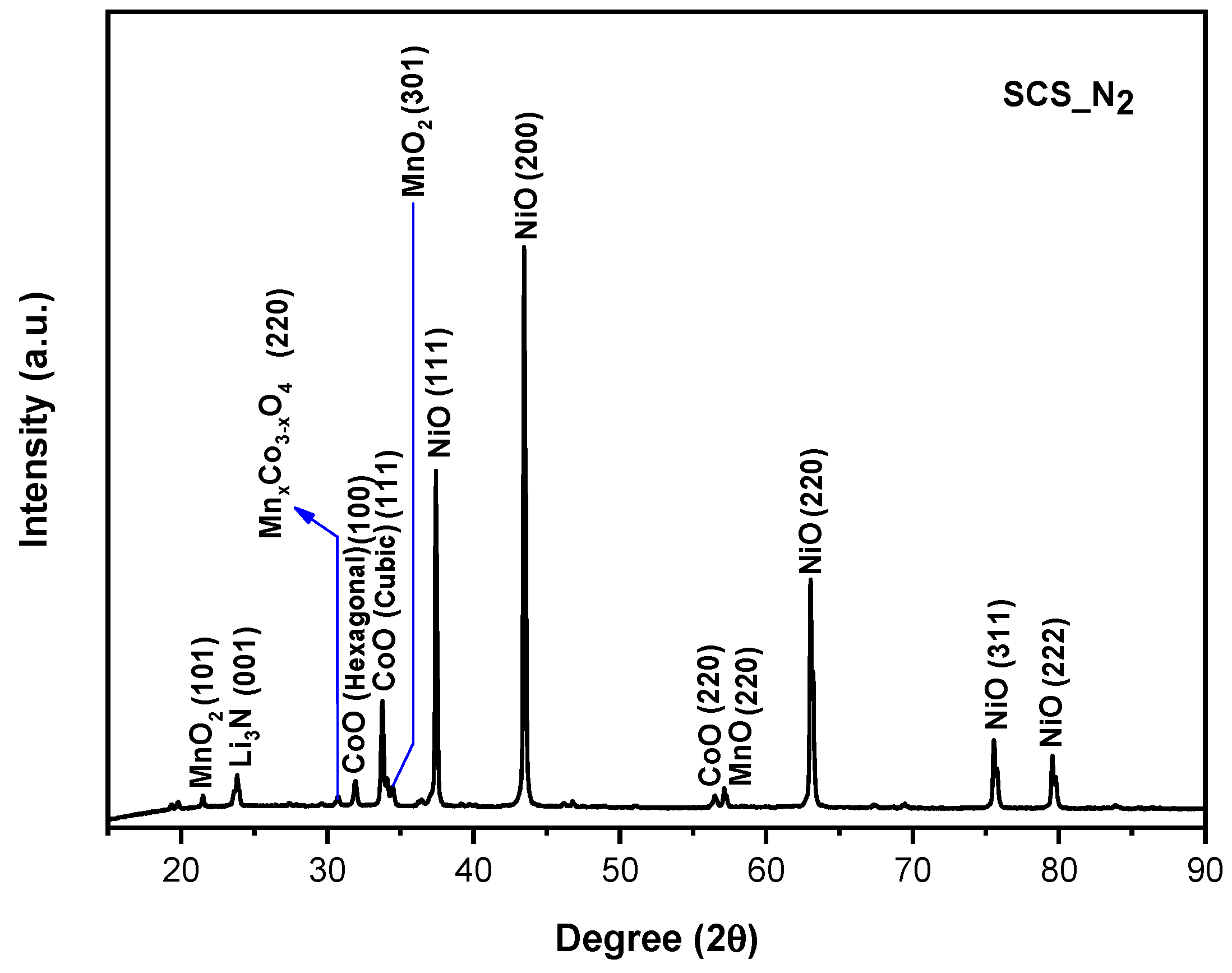
3.1. XRD

Figure 3 shows the distinct peaks of commercial NMC811, corresponding to the rhombohedral R-3m space group. The compound is isostructural to the layered α-NaFeO2. XRD data from the literature report that NMC cathode materials with a variable Ni content from 0.6 to 1.0 do not yield any noticeable variation in the crystallographic structure [24].
The XRD results of CPT-O2 and CPT-Air, as well as SCS-O2 and SCS-Air, demonstrated a strong agreement with the XRD analysis of the commercial NMC811, as depicted in Figure 4 and Figure 5, respectively. Results of Rietveld refinement are reported in Figures S1 and S2 in Supplementary Materials, and obtained crystallographic values are summarized in Table 1. We added the cubic and hexagonal cobalt oxides in the Rietveld refinements to explain the presence of the less intense peaks in the 2θ range between 30° and 38°, but these phases account for less than 2% by weight.
The change in intensity of diffraction peaks could be a result of altered atomic arrangements and changes in the scattering factors associated with the different cations [16]. Concerning the intensity of XRD peaks, many studies [7,16,25,26] demonstrated for NMC that when the intensity ratio of the (003) to the (104) diffraction peaks exceed 1.2, there is a minimal level of Ni2+/Li+ cation mixing. In fact, the degree of cation mixing decreases as this ratio increases. This change in intensity ratio is the result of changes in the structure factors associated with the different cation arrangements [16]. The intensity ratio R of (003)/(104) peaks for CPT-O2 and CPT-Air are 1.58 and 1.52, respectively, and for SCS-O2 and SCS-Air, the values are 1.76 and 1.72, respectively.
Results obtained from Rietveld refinements on the oxygen- and air-treated samples support (see Table 1) these conclusions since the Ni2+ occupation of the 3a sites is in the range between 7 and 9% and it is coherent with previous works (see [27] and the references therein). So, it can be concluded that the presence of oxygen generates quite pure samples, composed mainly of NMC811 with reduced cation mixing between Li+ and Ni2+.
A distinct difference was observed in samples calcinated under nitrogen: their XRD patterns do not correspond to the R-3m hexagonal structure, as shown in Figure 6 and Figure 7 for CPT-N2 and SCS-N2, respectively. The results of Rietveld refinement are reported in Figures S1 and S2 in Supplementary Materials, and the weight phase fraction observed in the samples, as derived from the Rietveld refinement, is reported in Table 2.
Figure 6 reports the XRD result for CPT-N2. Different phases were found in this sample: NiO, with the cubic crystallographic structure (h-CoO, Fm-3m space group), MnO2, with the orthorhombic crystallographic structure (Pnma space group), as well as CoO, with the cubic crystallographic structure (c-CoO, F-43m space group) and with the hexagonal one (P63mc space group). Obtained results indicate that, instead of the formation of a mixed oxide, separate TM oxides are formed when a non-oxidizing atmosphere is used during calcination. The phase fraction is linked to the relative amount of TMs fixed in the synthesis procedure.
Similarly, in the sample SCS-N2 (Figure 7), MnO2, c-CoO, h-CoO, and NiO are present. Additionally, we can see in Figure 7 that peaks corresponding to MnO, with the cubic crystallographic structure (F3-3m space group), are also present. A mixed cobalt manganese oxide, with the general formula MnxCo3−xO4, with the cubic crystallographic structure (Fd-3m space group) is identified as well, but the quality of experimental data is not sufficient to allow for determining the correct TM occupancies in the compound. Moreover, its weight fraction is rather low. Finally, observed XRD peaks with low intensity have been attributed to the formation of lithium nitride during the calcination. When the non-oxidizing atmosphere is used for calcination in the SCS synthesis, a set of various phases has been observed, likely out of equilibrium conditions. This can be due to the calcination treatment performed in SCS at higher temperatures with respect to CPT.

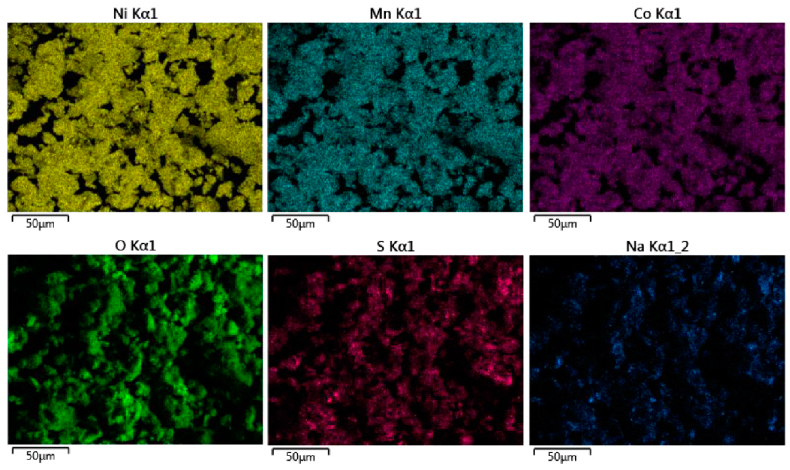
3.2. SEM and EDS Maps

SEM results, which are shown in Figure 8, highlight the effect of calcination under various atmospheric conditions on the particle morphology. In fact, particles prepared using the CPT method exhibit a preference for a more spherical and smoother morphology in comparison to particles synthesized using the SCS method, which show a flake-like shape. The spherical shape achieved through the CPT method may be attributed to the continuous control of parameters, such as temperature and pH, which ensures a balanced process of nucleation and growth. On the other hand, the SCS method, characterized by an exothermic reaction [15], leads to a rapid increase in temperature, which can accelerate the nucleation process without allowing sufficient time for particle growth. Consequently, particles produced by this method tend to be flaky and smaller in size when compared to those produced through the CPT method [9,28]. Nevertheless, following the calcination process at high temperatures, the smaller and flakier particles have a greater tendency to form agglomerates, compared to the larger and more spherical ones. This could be attributed to the fact that spherical particles have a smaller surface area-to-volume ratio in comparison to non-spherical particles of the same volume [29]. The reduced surface area limits the opportunities for particle-to-particle contact, bond formation, and attractive forces that contribute to agglomeration.
Concerning the EDS maps, the distribution of TMs was uniform across all samples, regardless of synthesis process and calcination environment applied. Results for CPT-O2 are reported in Figure 9, whereas maps for other samples are reported in Figures S3–S7 in Supplementary Materials.
With the CPT method, sulfur and sodium were detected, and this may be attributed to the use of TM sulfates and sodium hydroxide during the material synthesis process (Figure 9). According to Jouanneau et al. [30], employing TMs in the sulfate form leads to higher tap density of the oxide product compared to that obtained using the nitrate form. However, the inclusion of sulfur can potentially have detrimental effects on the brittleness and tendency for crack growth in cathode materials.

3.3. ICP

The ratio between the TM ions and lithium ions corresponds to the expected nominal ratio for the samples synthesized using the CPT method. On the other hand, the ICP data for samples synthesized using the SCS method reveal a different trend. In this case, obtained results indicate that, while the ratio between the TMs remains consistent with the nominal one, the ratio of lithium deviates significantly from the expected one (Table 3). The difference in Li content between samples obtained by CPT and SCS could be attributed to the fact that CPT takes advantage of a controlled environment. In fact, with CPT, the addition of lithium to the precursor was performed in a glove box filled with Ar as an inert atmosphere, while in the SCS approach, starting materials got exposed to an intense exothermic reaction [15] without any possibility of controlling the lithium evaporation. Therefore, the CPT method shows lower Li wastage compared to SCS, indicating its superior efficiency.

3.4. PSD

Table 4 displays the results of particle size analysis, which underlined that only D50 of CPT-O2 and CPT-Air is less than 15 µm. Normally, the suggestion for the size distribution for the NMC particles is to obtain D90 lower than 20 µm and the D50 at approximately 10 µm, preferably not exceeding 15 µm [9]. Small particles have a high probability of undergoing side reactions, contributing to particle agglomeration, which can result in an increased diffusion pathway for lithium ions, leading to a decrease in the efficiency of the battery. On the contrary, for large particles, the ion diffusion is hindered, and the electrode/electrolyte interface tends to be less favorable due to a decrease in available surface area for efficient electrochemical reactions [31].

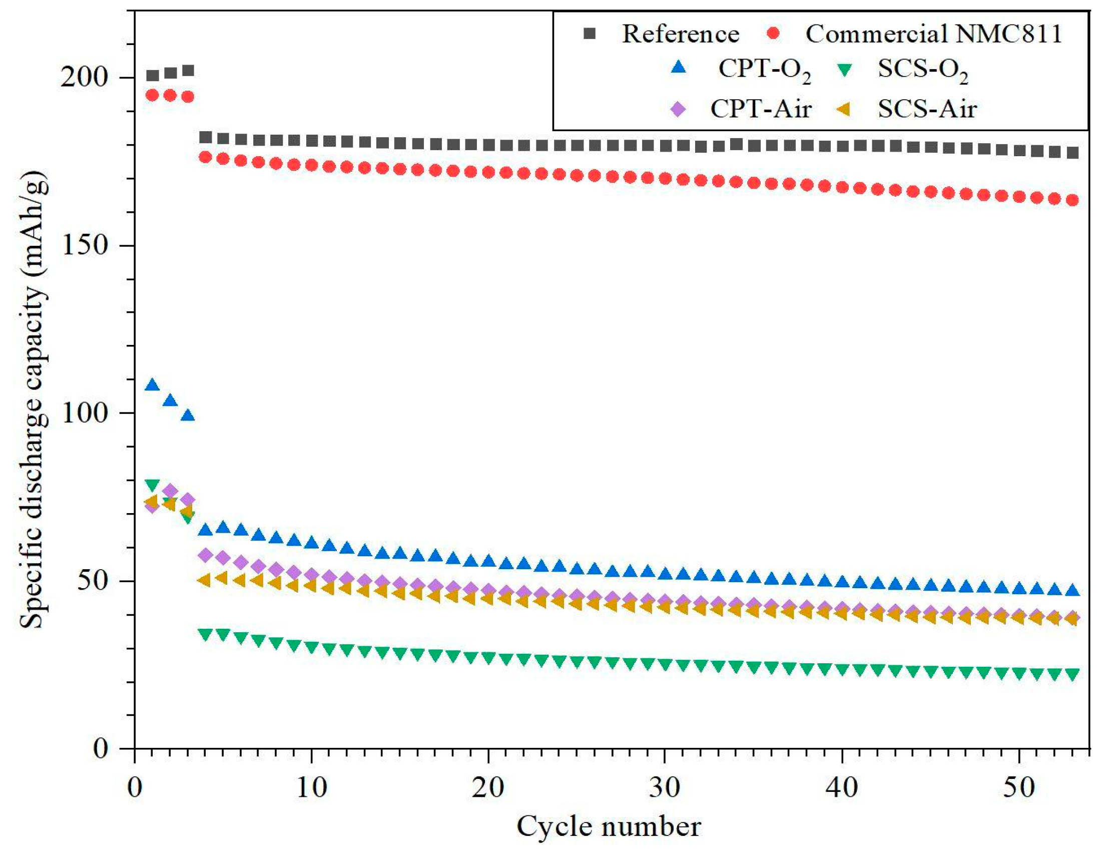
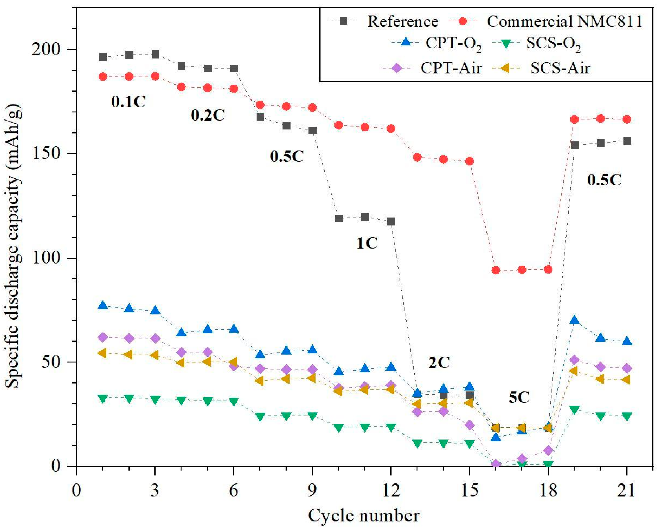
3.5. Cycling and C-Rate Performance Test

Figure 10 shows the results of the electrodes tested with a cycling performance test, compared to the results obtained with a commercial electrode (with NMC811 as cathode active material), called reference, and an electrode prepared with the commercial NMC811 powder. The electrodes produced with CPT-O2 and CPT-Air powders exhibited a higher specific discharge capacity, compared to those synthesized using the SCS approach. Regarding the atmospheric conditions during the calcination process within the CPT method, the sample calcinated under oxygen atmosphere showed a higher specific capacity compared to that obtained with air atmosphere. The electrodes CPT-N2 and SCS-N2 did not display any discharge capacity. The explanation for their behavior can be traced back to their XRD results: the mixture of oxides of which they are composed is not able to intercalate the lithium ion during the charge/discharge processes. So, the corresponding results are not included in Figure 10.
Figure 11 displays the C-rate performances of prepared electrodes. Among all samples, the CPT-O2 electrode exhibits the highest specific discharge capacity at any C-rate with respect to SCS-O2, CPT-Air, and SCS-Air. Considering the cycling performances, various parameters can be examined and analyzed to reach a definitive conclusion. One parameter is the morphology of the active material, which has the potential to impact the overall electrochemical outcomes. The CPT particles have a small Particle Size Distribution, allowing an easy intercalation and deintercalation of lithium ions [32]. Considering all mentioned factors, it can be concluded that, between the two considered preparation methods, the NMC samples synthesized through CPT are the best candidate for electrochemical applications.

4. Conclusions

The influence of a partially oxidizing atmosphere (air), a totally oxidizing atmosphere (oxygen), and a non-oxidizing atmosphere (nitrogen) on the properties of NMC811 synthesized by two different methods (CPT and SCS) was investigated.
  • The SEM and PSD characterization tests showed that NMC811 synthesized through the CPT approach displayed a finer morphology, with particle sizes similar to those of commercial NMC811.
  • As evidence of the XRD analysis, the samples which were treated under the nitrogen atmosphere are composed of a mixture of not layered Mn, Co, and Ni oxides. Therefore, nitrogen-treated samples are not able to intercalate lithium ions and they do not show any charge/discharge capacity during the cycling performance test.
  • While the electrochemical performance of coin cells can be influenced by various factors including the electrolyte, anode material, and assembling process, it is noteworthy that CPT-O2 exhibited the highest discharge capacity and capacity retention compared to all other samples, which is correlated to the morphology of the cathode particles.
The results of the electrochemical testing should be evaluated considering that the commercial cathode materials were used as a reference and were optimized by the producer to reach good performances. The preparation procedure was not disclosed. On the other hand, our goal was to study the effect of the calcination atmosphere on the structure, morphology, and performances. So, we do not expect to obtain results equal or superior to the benchmark materials since we know that we must optimize many other synthesis parameters.
The two synthesis procedures (SCS and CPT) are very different in terms of economic investment and sustainability. In future investigations, it is advisable to give precedence to the CPT approach over the SCS one. Furthermore, employing an oxygen atmosphere during the calcination process is recommended. Within the CPT approach, it is suggested to adjust parameters such as pH, temperature, synthesis duration, and stirring rate to attain a more optimized particle morphology. Moreover, other gases such as water vapor could be used to modify the oxidizing calcination atmosphere.

Supplementary Materials

The following supporting information can be downloaded at: https://www.mdpi.com/article/10.3390/cryst14020137/s1: Figure S1. Rietveld analysis for CPT samples obtained in O2 atmosphere (top), air atmosphere (middle), N2 atmosphere (bottom). Figure S2. Rietveld analysis for SCS samples obtained in O2 atmosphere (top), air atmosphere (middle), N2 atmosphere (bottom). Figure S3. EDS map of SCS-O2. Figure S4. EDS map of CPT-Air. Figure S5. EDS map of SCS-Air. Figure S6. EDS map of CPT-N2. Figure S7. EDS map of SCS-N2.

Author Contributions

Conceptualization, M.F.S., A.T., K.G., C.N. and M.B.; methodology, A.T., M.D., G.N. and M.G.; validation, R.R., G.N. and M.D.; investigation, A.T., K.G. and A.M.; data curation, A.M.; writing—review and editing, K.G., M.F.S. and A.T.; visualization, R.R.; supervision, C.N. and M.B. All authors have read and agreed to the published version of the manuscript.

Funding

This work is supported by Centro Ricerche Fiat (CRF), Company of San Paolo (project ex-post “New Materials for Solid State Batteries”), Chemistry Department of University of Turin. Authors acknowledge support from Project CH4.0 under the MUR program “Dipartimenti di Eccellenza 2023-2027” (CUP: D13C22003520001).

Data Availability Statement

The original contributions presented in the study are included in the article/supplementary material, further inquiries can be directed to the corresponding author/s.

Acknowledgments

The authors acknowledge DISAT Department of Polytechnic of Turin for the assistance on the preparation of electrodes.

Conflicts of Interest

Giovanna Nicol and Mattia Giuliano are employed by the company Centro Ricerche FIAT S.C.p.A company. Matteo Dotoli is employed by the COMAU S.p.A company. The remaining authors declare that the research was conducted in the absence of any commercial or financial relationships that could be construed as a potential conflict of interest.

References

  1. Mathew, V.; Sambandam, B.; Kim, S.; Kim, S.; Park, S.; Lee, S.; Lee, J.; Park, S.; Song, J.; Kim, J. High-voltage cathode materials by combustion-based preparative approaches for Li-ion batteries application. J. Power Sources 2020, 472, 228368. [Google Scholar] [CrossRef]
  2. Hou, P.; Zhang, H.; Zi, Z.; Zhang, L.; Xu, X. Core-shell and concentration-gradient cathodes prepared via co-precipitation reaction for advanced lithium-ion batteries. J. Mater. Chem. A Mater. 2017, 5, 4254–4279. [Google Scholar] [CrossRef]
  3. Li, W.; Erickson, E.M.; Manthiram, A. High-nickel layered oxide cathodes for lithium-based automotive batteries. Nat. Energy 2020, 5, 26–34. [Google Scholar] [CrossRef]
  4. Peralta, D.; Salomon, J.; Colin, J.F.; Boulineau, A.; Fabre, F.; Bourbon, C.; Amestoy, B.; Gutel, E.; Bloch, D.; Patoux, S. Submicronic LiNi1/3Mn1/3Co1/3O2 synthesized by co-precipitation for lithium ion batteries—Tailoring a classic process for enhanced energy and power density. J. Power Sources 2018, 396, 527–532. [Google Scholar] [CrossRef]
  5. Li, J.; Li, H.; Stone, W.; Weber, R.; Hy, S.; Dahn, J.R. Synthesis of Single Crystal LiNi0.5Mn0.3Co0.2O2 for Lithium Ion Batteries. J. Electrochem. Soc. 2017, 164, A3529–A3537. [Google Scholar] [CrossRef]
  6. Li, H.; Li, J.; Ma, X.; Dahn, J.R. Synthesis of Single Crystal LiNi0.6Mn0.2Co0.2O2 with Enhanced Electrochemical Performance for Lithium Ion Batteries. J. Electrochem. Soc. 2018, 165, A1038–A1045. [Google Scholar] [CrossRef]
  7. Ahaliabadeh, Z.; Kong, X.; Fedorovskaya, E.; Kallio, T. Extensive comparison of doping and coating strategies for Ni-rich positive electrode materials. J. Power Sources 2022, 540, 231633. [Google Scholar] [CrossRef]
  8. Kasnatscheew, J.; Röser, S.; Börner, M.; Winter, M. Do Increased Ni Contents in LiNixMnyCozO2 (NMC) Electrodes Decrease Structural and Thermal Stability of Li Ion Batteries? A Thorough Look by Consideration of the Li+ Extraction Ratio. ACS Appl. Energy Mater. 2019, 2, 7733–7737. [Google Scholar] [CrossRef]
  9. Malik, M.; Chan, K.H.; Azimi, G. Review on the synthesis of LiNixMnyCo1−x−yO2 (NMC) cathodes for lithium-ion batteries. Mater. Today Energy 2022, 28, 101066. [Google Scholar] [CrossRef]
  10. Leifer, N.; Penki, T.; Nanda, R.; Grinblat, J.; Luski, S.; Aurbach, D.; Goobes, G. Linking structure to performance of Li1.2Mn0.54Ni0.13Co0.13O2 (Li and Mn rich NMC) cathode materials synthesized by different methods. Phys. Chem. Chem. Phys. 2020, 22, 9098–9109. [Google Scholar] [CrossRef] [PubMed]
  11. You, B.; Wang, Z.; Shen, F.; Chang, Y.; Peng, W.; Li, X.; Guo, H.; Hu, Q.; Deng, C.; Yang, S.; et al. Research Progress of Single-Crystal Nickel-Rich Cathode Materials for Lithium Ion Batteries. Small Methods 2021, 5, 2100234. [Google Scholar] [CrossRef] [PubMed]
  12. Dong, H.; Koenig, G.M. A review on synthesis and engineering of crystal precursors produced: Via coprecipitation for multicomponent lithium-ion battery cathode materials. CrystEngComm 2020, 22, 1514–1530. [Google Scholar] [CrossRef]
  13. Cho, J. LiNi0.74Co0.26−xMgxO2 cathode material for a Li-ion cell. Chem. Mater. 2000, 12, 3089–3094. [Google Scholar] [CrossRef]
  14. Ying, J.; Wan, C.; Jiang, C.; Li, Y. Preparation and characterization of high-density spherical LiNi0.8Co0.2O2 cathode material for lithium secondary batteries. J. Power Sources 2001, 99, 78–84. [Google Scholar] [CrossRef]
  15. Patil, K.C.; Aruna, S.T.; Mimani, T. Combustion synthesis: An update. Curr. Opin. Solid State Mater. Sci. 2002, 6, 507–512. [Google Scholar] [CrossRef]
  16. Mugumya, J.H.; Rasche, M.L.; Rafferty, R.F.; Patel, A.; Mallick, S.; Mou, M.; Bobb, J.A.; Gupta, R.B.; Jiang, M. Synthesis and Theoretical Modeling of Suitable Co-precipitation Conditions for Producing NMC111 Cathode Material for Lithium-Ion Batteries. Energy Fuels 2022, 36, 12261–12270. [Google Scholar] [CrossRef]
  17. Hua, W.; Wang, K.; Knapp, M.; Schwarz, B.; Wang, S.; Liu, H.; Lai, J.; Müller, M.; Schökel, A.; Missyul, A.; et al. Chemical and Structural Evolution during the Synthesis of Layered Li(Ni,Co,Mn)O2 Oxides. Chem. Mater. 2020, 32, 4984–4997. [Google Scholar] [CrossRef]
  18. Zheng, J.; Yan, P.; Estevez, L.; Wang, C.; Zhang, J.G. Effect of calcination temperature on the electrochemical properties of nickel-rich LiNi0.76Mn0.14Co0.10O2 cathodes for lithium-ion batteries. Nano Energy 2018, 49, 538–548. [Google Scholar] [CrossRef]
  19. Bockholt, H.; Haselrieder, W.; Kwade, A. Intensive powder mixing for dry dispersing of carbon black and its relevance for lithium-ion battery cathodes. Powder Technol. 2016, 297, 266–274. [Google Scholar] [CrossRef]
  20. Wang, M.; Hu, J.; Wang, Y.; Cheng, Y.-T. The Influence of Polyvinylidene Fluoride (PVDF) Binder Properties on LiNi0.33Mn0.33Co0.33O2 (NMC) Electrodes Made by a Dry-Powder-Coating Process. J. Electrochem. Soc. 2019, 166, A2151–A2157. [Google Scholar] [CrossRef]
  21. Primo, E.N.; Chouchane, M.; Touzin, M.; Vazquez, P.; Franco, A.A. Understanding the calendering processability of Li(Ni0.33Mn0.33Co0.33)O2-based cathodes. J. Power Sources 2021, 488, 229361. [Google Scholar] [CrossRef]
  22. Available online: https://www.icdd.com/ (accessed on 20 January 2024).
  23. Lutterotti, L.; Matthies, S.; Wenk, H.-R. MAUD: A friendly Java program for material analysis using diffraction. IUCr Newsl. CPD 1999, 21, 14–15. [Google Scholar]
  24. Yan, W.; Yang, S.; Huang, Y.; Yang, Y.; Yuan, G. A review on doping/coating of nickel-rich cathode materials for lithium-ion batteries. J. Alloys Compd. 2020, 819, 153048. [Google Scholar] [CrossRef]
  25. Xu, Z.; Xiao, L.; Wang, F.; Wu, K.; Zhao, L.; Li, M.R.; Zhang, H.L.; Wu, Q.; Wang, J. Effects of precursor, synthesis time and synthesis temperature on the physical and electrochemical properties of Li(Ni1−x−yCoxMny)O2 cathode materials. J. Power Sources 2014, 248, 180–189. [Google Scholar] [CrossRef]
  26. Liu, S.; Dang, Z.; Liu, D.; Zhang, C.; Huang, T.; Yu, A. Comparative studies of zirconium doping and coating on LiNi0.6Co0.2Mn0.2O2 cathode material at elevated temperatures. J. Power Sources 2018, 396, 288–296. [Google Scholar] [CrossRef]
  27. Li, J.; Liang, G.; Zheng, W.; Zhang, S.; Davey, K.; Pang, W.K.; Guo, Z. Addressing cation mixing in layered structured cathodes for lithium-ion batteries: A critical review. Nano Mater. Sci. 2022, 5, 404–420. [Google Scholar] [CrossRef]
  28. Zhang, H.; Xu, J.; Zhang, J. Surface-Coated LiNi0.8Co0.1Mn0.1O2 (NCM811) Cathode Materials by Al2O3, ZrO2, and Li2O-2B2O3 Thin-Layers for Improving the Performance of Lithium Ion Batteries. Front. Mater. 2019, 6, 1–10. [Google Scholar] [CrossRef]
  29. Butt, H.; Graf, K.; Kappl, M. Physics and Chemistry of Interfaces; John Wiley & Sons: Hoboken, NJ, USA, 2003. [Google Scholar] [CrossRef]
  30. Jouanneau, S.; Eberman, K.W.; Krause, L.J.; Dahn, J.R. Synthesis, Characterization, and Electrochemical Behavior of Improved Li[NixCo1−2xMnx]O2 (0.1 ≤ x ≤ 0.5). J. Electrochem. Soc. 2003, 150, A1637–A1642. [Google Scholar] [CrossRef]
  31. Wood, M.; Li, J.; Du, Z.; Daniel, C.; Dunlop, A.R.; Polzin, B.J.; Jansen, A.N.; Krumdick, G.K.; Wood, D.L. Impact of secondary particle size and two-layer architectures on the high-rate performance of thick electrodes in lithium-ion battery pouch cells. J. Power Sources 2021, 515, 230429. [Google Scholar] [CrossRef]
  32. Pişkin, B.; Uygur, C.S.; Aydınol, M.K. Morphology effect on electrochemical properties of doped (W and Mo) 622NMC, 111NMC, and 226NMC cathode materials. Int. J. Hydrogen Energy 2020, 45, 7874–7880. [Google Scholar] [CrossRef]
Figure 1. Workflow and processes adopted in the present work.
Crystals 14 00137 g001
Figure 2. Components of a coin cell with NMC811 cathode and lithium metal anode. The cell is composed of a metallic lithium anode and the cathode materials deposited on an aluminum current collector. The two electrodes are divided using the polymeric separator impregnated by the electrolyte. The spacers and the spring are used to apply pressure and to keep the cell components in good contact. The cell is enclosed into a metallic case composed of two parts (negative and positive) that are not electrically connected.
Crystals 14 00137 g002
Figure 3. XRD of the commercial NMC811.
Crystals 14 00137 g003
Figure 4. XRD results of CPT-O2 and CPT-Air.
Crystals 14 00137 g004
Figure 5. XRD results of SCS-O2 and SCS-Air.
Crystals 14 00137 g005
Figure 6. XRD results of CPT-N2.
Crystals 14 00137 g006
Figure 7. XRD results of SCS-N2.
Crystals 14 00137 g007
Figure 8. SEM images of (A) SCS-O2, (B) SCS-Air, (C) SCS-N2, (D) CPT-O2, (E) CPT-Air, and (F) CPT-N2.
Crystals 14 00137 g008
Figure 9. EDS map of CPT-O2.
Crystals 14 00137 g009
Figure 10. Cycling performance of prepared electrodes.
Crystals 14 00137 g010
Figure 11. C-rate performance of the electrodes.
Crystals 14 00137 g011
Table 1. The lattice parameters and site occupancies of Li in 3b Wickoff position and Ni in 3a Wickoff position for the CPT-O2, CPT-Air, SCS-O2, and SCS-Air samples obtained using the Rietveld refinement method. Rexp is the statistically expected R value, and Rwp is the weighted-profile R value.
Samplea (Å)c (Å)I(003)/I(104)OLi3bONi3aRexpRwp
CPT-O22.68513.2741.580.0560.0720.777.54
CPT-Air2.68513.2841.520.0170.0760.736.81
SCS-O22.68413.2731.760.0510.0720.737.70
SCS-Air2.69013.3371.720.0410.0750.727.78
Table 2. Composition of CPT-N2 and SCS-N2 samples obtained from Rietveld refinement. Rexp is the statistically expected R value, and Rwp is the weighted-profile R value.
SampleNiOc-CoOh-CoOMnO2MnOMnxCo3−xO4Li3NRexpRwp
CPT-N289.70.14.85.4---0.7710.09
SCS-N269.61.75.32.15.10.515.70.767.48
Table 3. ICP results of the different NMC811 cathode materials synthesized by the CPT and SCS synthesis methods and calcinated under oxygen, air, and nitrogen atmospheres at 900 °C.
Sample IDNominal Stoichiometric Ratio of Li:TMsICP Result in Stoichiometric Ratio of Li:TMs
CPT-O21.15:1.001.07:1.00
CPT-Air1.15:1.001.10:1.00
CPT-N21.15:1.000.96:1.00
SCS-O22.00:1.001.54:1.00
SCS-Air2.00:1.001.41:1.00
SCS-N22.00:1.001.29:1.00
Table 4. Particle Size Distribution in D10, D50, and D90 for the samples synthesized through the CPT and SCS, sintered at different atmospheres at 900 °C.
Sample IDD10 (µm)D50 (µm)D90 (µm)
CPT-Air3.0813.5732.53
CPT-O23.4614.1928.25
CPT-N29.1820.8137.99
SCS-Air9.3518.9933.02
SCS-O212.9925.0542.29
SCS-N210.4625.0544.34
Disclaimer/Publisher’s Note: The statements, opinions and data contained in all publications are solely those of the individual author(s) and contributor(s) and not of MDPI and/or the editor(s). MDPI and/or the editor(s) disclaim responsibility for any injury to people or property resulting from any ideas, methods, instructions or products referred to in the content.

