Article

Effects of the Number of Layers and Thickness Ratio on the Impact Fracture Behavior of AA6061/AA7075 Laminated Metal Composites

International Joint Laboratory for Light Alloys, Ministry of Education, College of Materials Science and Engineering, Chongqing University, Chongqing 400044, China
*
Authors to whom correspondence should be addressed.
Crystals 2024, 14(1), 44; https://doi.org/10.3390/cryst14010044
Submission received: 21 October 2023 / Revised: 7 December 2023 / Accepted: 15 December 2023 / Published: 28 December 2023
(This article belongs to the Special Issue Advances in Laminated Metallic Composites)

Abstract

:
The initial thickness ratio and number of layers of dissimilar metal components greatly influence the impact performance of laminated metal composites. In this paper, positive and lateral impact tests of 5-layer composite sheets with thickness ratios of 3:1, 1.35:1, and 1:2 and 80-layer composite sheets prepared by ARB (accumulative roll bonding) were conducted to study the influences of the thickness ratio and layer number on the impact fracture behavior of composite sheets. The results showed that the higher the proportion of AA7075, the higher the bending strength of the AA6061/AA7075 laminated composite sheet; compared with the 5-layer composite sheet, the side impact performance of the 80-layer composite sheet is obviously improved, and its side impact strength, energy absorbed in the crack initiation stage, and crack propagation stage are better than those of the 5-layer composite sheet. In addition, the toughening mechanism of the 80-layer composite sheet is mainly that the increase in the number of layers makes the cracks deflect more frequently. Under the rapid impact load, the impact energy absorbed by the sample increases with the increase in the number of layers.

1. Introduction

With the development of modern science and technology, the performance of a single material is increasingly unable to meet the needs of the market, and the market demand for high-performance materials forces the constant development of new processes to prepare materials with excellent comprehensive performance, such as fiber-reinforced composites [1], particle-reinforced composites [2], and laminated metal composites [3,4,5,6]. Among them, laminated metal composites can maintain the original advantages of their own materials, while achieving comprehensive properties that cannot be achieved by a single metal material [7]. The preparation process of a layered metal composite sheet is to make two or more metal sheets firmly metallurgically bonded via certain physical or chemical methods, and its common preparation processes are mainly the explosive composite method, diffusion welding method, spray deposition method, and rolling composite method. Among them, the laminated composite prepared by the rolling process is one of the important technologies widely studied and applied on a large scale at present because of its simple industry and low cost [8]. At present, roll bonding technology has been successfully applied in the preparation of materials involving various metals, such as Cu/Al [9,10], Ti/Al [11,12,13], Al/Cu/SiC [14], Al/Ni/Cu [15], Cu/Nb [16], Ni/Fe [17], Nb/Zr [18], and Al/Al alloys [19,20,21,22]. However, in the process of the composite rolling of dissimilar metals, the two metals with different properties often exhibit deformation disharmony, which leads to fluctuations in the thickness of each component layer in the rolling direction and the occurrence of difficult to deform metal necking or even fracture.
The AA7075 aluminum alloy belongs to the Al-Zn-Mg-Cu superhard aluminum alloy, which is a common kind of 7xxx aluminum alloy, and is often used as an aircraft frame and high-strength accessories in the aerospace field. However, the AA7075 aluminum alloy is expensive and has poor corrosion resistance [23] and welding performance [24]. The tensile strength of the AA6061 aluminum alloy is slightly lower than that of the 7xxx aluminum alloy, and the price is relatively cheap, and it has good corrosion resistance, weldability, and oxidation resistance [25,26]. In recent years, many researchers have rolled and compounded two materials with different properties to prepare composite materials with better comprehensive properties, for example, a high-strength and low-plasticity 7xxx and low-strength and high-plasticity 1xxx aluminum alloy [22]. However, in the rolling process of heterogeneous materials, there are interface structure phenomena with poor properties, such as uncoordinated deformation of component metals, necking of hard components, low interface bonding strength, and uneven interface. Gomez et al. [27] proposed that different metals can be deformed synchronously only when the flow stress ratio is lower than 2~2.5. O. Yazar et al. [28] reported that in order to keep different metal layers continuous and uniform during deformation, the critical flow stress ratio of soft and hard layers should be less than 2. In addition, the initial thickness ratio of component metals also affects the interface behavior of composite sheets. By studying the interface morphology of Ni/Ag and Fe/Ag composite sheets, Lee et al. [29] draw the following conclusion: the greater the thickness ratio of the hard layer metal, the greater the critical deformation required for rolling, and the more difficult necking, so the initial thickness ratio of the soft and hard layer is also a factor affecting the interface morphology. Compared with the rolling composite of dissimilar metals such as 1xxx and 7xxx aluminum alloys, the mechanical properties such as the strength and plasticity of 6xxx and 7xxx aluminum alloys are less different, and the degree of co-deformation is lower. In addition, if the advantages of the two are integrated by the rolling composite process, on the one hand, the consumption of the expensive AA7075 aluminum alloy can be saved, and on the other hand, the composite sheet can have the good corrosion resistance and weldability of the AA6061 aluminum alloy.
During the application of an aluminum alloy composite sheet in aerospace or automotive applications, it is inevitable to be hit by external forces. Therefore, in order to better understand and further apply layered metal composites, it is very important to evaluate the mechanical properties of these materials under the condition of impact damage. In recent years, scholars at home and abroad have conducted a lot of research on the fracture behavior and mechanism of laminated composites [30]. Barabash et al. [3] found that the existence of a layer interface will change the stress state of the material. Gao et al. [31] thought that the change in the stress state is beneficial to restrain crack initiation and propagation. Wang et al. [6] formed layered composites by introducing ductile Ti layers into TiB/TA15 materials and found that the existence of ductile Ti layers provided an additional back stress strengthening effect, which was conducive to crack passivation and crack deflection, and, finally, showed the improvement in the comprehensive properties of the materials. Tasdemirci et al. [32] simulated the fracture process of laminated composite sheets at high strain rates by establishing a numerical model. Cepeda-Jimenez C et al. [33,34] found that the impact absorption energy of an AA7075/AA2024 composite sheet treated with T6 was more than 20 times that of AA7075 and more than 7 times that of AA2024. Ibrahim et al. [35] studied the effects of the alloy composition and solidification conditions on the impact toughness and fracture morphology of an Al-Si-Cu-Mg base alloy. In addition, many scholars have studied the impact toughness, fracture, and crack propagation behavior of layered metal composites under impact loads. It has been reported that the toughness of laminar composite panels can be improved by external toughening mechanisms such as crack deflection, crack passivation, and interface delamination [36]. For layered composites with a large difference in the toughness of component metals, the cracks generated in the brittle layer will be passivated by the adjacent ductile layers when subjected to a rapid impact load, which shows that the stress intensity factor and crack growth driving force decrease. However, there are few reports about the impact fracture behavior of composite sheets caused by the layer thickness ratio and layer number [22]. Therefore, it is necessary to study the effect of the initial thickness and number of layers on the interface structure and impact properties of aluminum alloy laminated composites.
In this paper, 5-layer and 80-layer AA6061/AA7075 laminated composite sheets with different layer thickness ratios were successfully prepared by the rolling process, and the effects of the layer thickness ratio and the number of layers on the microstructure and interfacial structure of the laminated sheets were investigated. In addition, in order to investigate the initial layer thickness ratio and number of layers on the fracture mechanism of the AA6061/AA7075 laminated composite sheet, the impact toughness, fracture, and crack extension of the 5-layer and 80-layer AA6061/AA7075 laminated composite sheet were investigated, which provide the basis for the further understanding of the composite material enhancement mechanism and crack fracture mechanism.

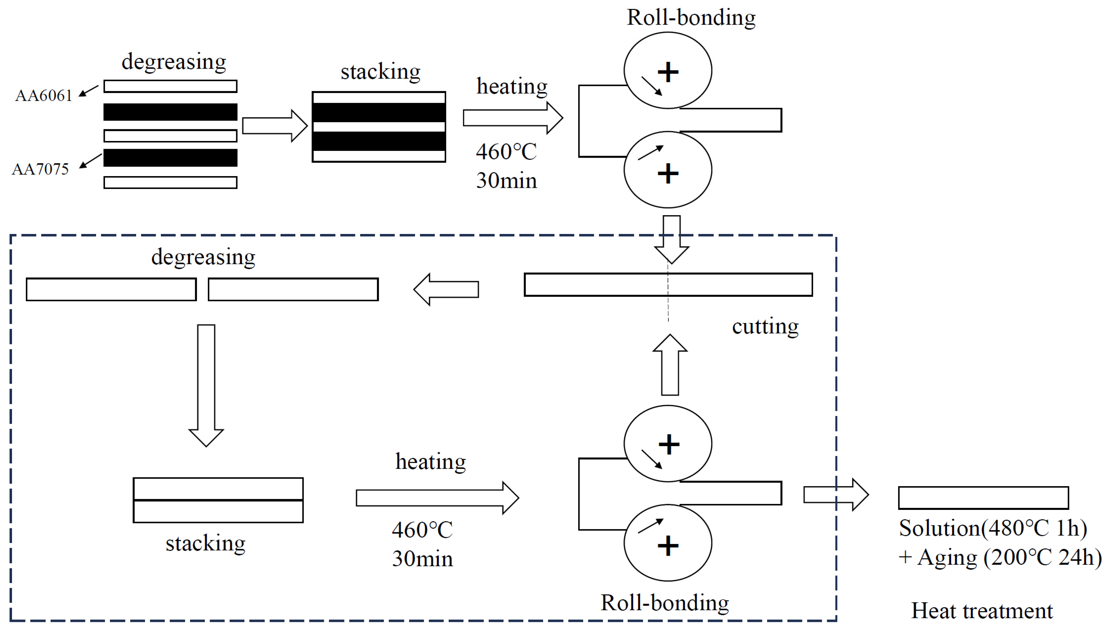
2. Experimental Materials and Methods

The research materials are AA6061 and AA7075, and the chemical compositions of the two aluminum alloys are provided in Table 1. The sheet metal used in the roll bonding process exhibits dimensions of 120 mm × 100 mm, and the thickness ratios of the AA6061 and AA7075 sheets are set to 3:1 (2.0 mm + 1.0 mm), 1.35:1 (1.8 mm + 2.0 mm), and 1:2 (1.0 mm + 3.0 mm), and the initial thickness values are shown in Table 2.
The schematic diagram of the laminated metal composite plate preparation is shown in Figure 1. Before the roll bonding of the laminated metal composite sheets, the surface of the initial sheet to be composited is mechanically sanded by an electric steel brush to remove oil and the oxide film on the surface of the aluminum alloy, a hardened layer of a certain thickness is formed to obtain a clean composite surface with a certain roughness, and any oil on the surface of the sheet to be composited is removed with alcohol. After blow-drying, the AA6061 and AA7075 sheets are stacked into a “sandwich” structure in the order of AA6061/AA7075/AA6061/AA7075/AA6061 followed by riveting. The stacked sheets are preheated at 460 °C for 30 min and then hot rolled to obtain a thickness of a 4 mm composite sheet after rolling. Each 5-layer composite sheet is then cut into two sections, and surface treatment, stacking, preheating, and roll bonding are again performed to ensure 50% of the pressure drops per pass. The above steps are repeated to obtain 80 layers of the AA6061/AA7075/AA6061/AA7075/AA6061 sheets with thickness ratios of 3:1, 1.35:1, and 1:2. Since the main bearing phase in this paper is the AA7075 aluminum alloy, the heat treatment process involving “exposure to a solid solution at 475 °C for 1 h and aging at 200 °C for 24 h” is used to enhance the treatment of the different samples [37].
The microstructure and structure of the composite sheets were studied via scanning electron microscopy (SEM, TESCAN MIRA3). To ensure the surface quality of the samples and facilitate the subsequent observation analysis, the surface of the samples was polished with a polishing solution (10 mL perchloric acid + 90 mL absolute ethanol) to facilitate 20-V electrolytic lamination for 15 s, after which, a ZBC-300 automatic pendulum impact test machine was used for conducting the Charpy impact test. The impact specimen size was 40 mm (length), 7 mm (width), and 4 mm (thickness), and the depth of the V-shaped incision was 1 mm along the rolling direction. The impact velocity of the test was 5.2 m/s, and the pendulum pre-raised angle was 150°. Each sample was replicated at least three times to guarantee the reliability of the results.

3. Results and Discussion

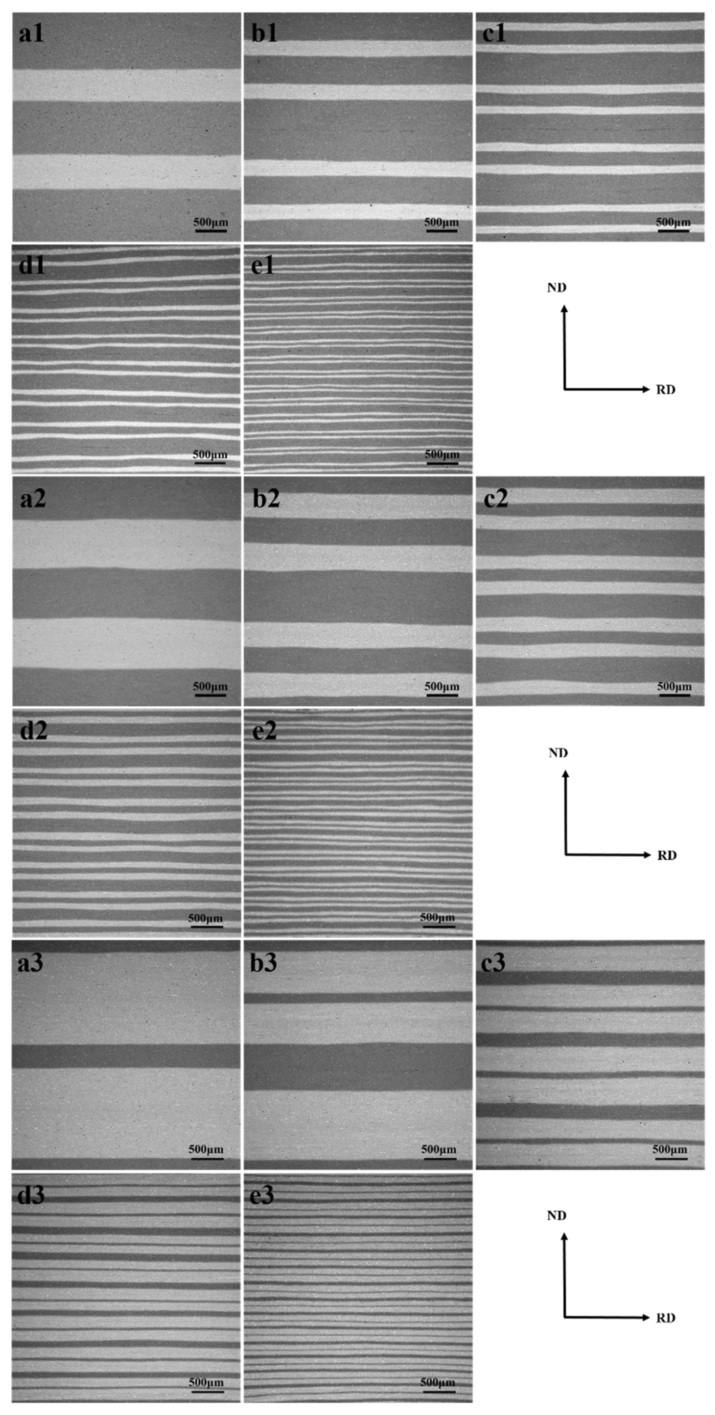
3.1. Effect on the Interface Structure of Composite Sheet

The macroscopic interface morphology of the rolling direction (RD)/normal direction (ND) surface of the aluminum alloy laminated composite sheets with different thickness ratios and different numbers of layers is shown in Figure 2. In the process of roll bonding, the deformation of two metals with different properties usually exhibits incongruity, which in turn leads to fluctuations along the ND of the macroscopic interface of the composite sheet and necking fracture of hard metals. In the composite process of the AA6061 aluminum alloy and AA7075 aluminum alloy, no serious interfacial fluctuation phenomenon occurred in the 5- and 80-layer composite sheets because the high rolling temperature in the roll bonding process softens the material, which is conducive to the flow of metal near the interface and reduces the occurrence of plastic instability behavior. In addition, as shown in Figure 1, the higher the proportion of AA7075 layers is, the flatter the structure of the interface, and this phenomenon can be analyzed by the theoretical model derived by Reihanian et al. [38]:
ε ¯ n e c k * = n C 3 ( 1 H ) [ 1 A S A C ( ε ¯ n e c k * ) n S n C ]
where ε ¯ n e c k * is the critical equivalence change corresponding to the necking of the hard layer, H is the ratio of the total thickness of the core component layer of the composite sheet to the total thickness of the composite sheet, nc and ns are the process hardening index values of the core and surface component layers, respectively, and AC and AS are the strength coefficient values of the core and surface component layers, respectively. The core component layers in this article are all AA7075, and the surface component layers are all AA6061.
The substitution of the AA6061 and AA7075 parameters listed in Table 3 into Equation (1) shows that the critical equivalence effects needed for the necking of the hard layer of the AA6061/AA7075 composite sheets with a thickness ratio of 3:1, 1.35:1, and 1:2 are 0.62, 0.79, and 1.30, respectively. No hard layer necking-induced shrinkage phenomenon was found in the 80-layer sheets under the three thickness ratios (an equivalent effect of approximately 4) prepared involving four accumulative roll bonding (ARB) cycles. The main reason for the deviation between the theoretical values and the actual results is that repeated intermediate annealing partially eliminates the cumulative strain.

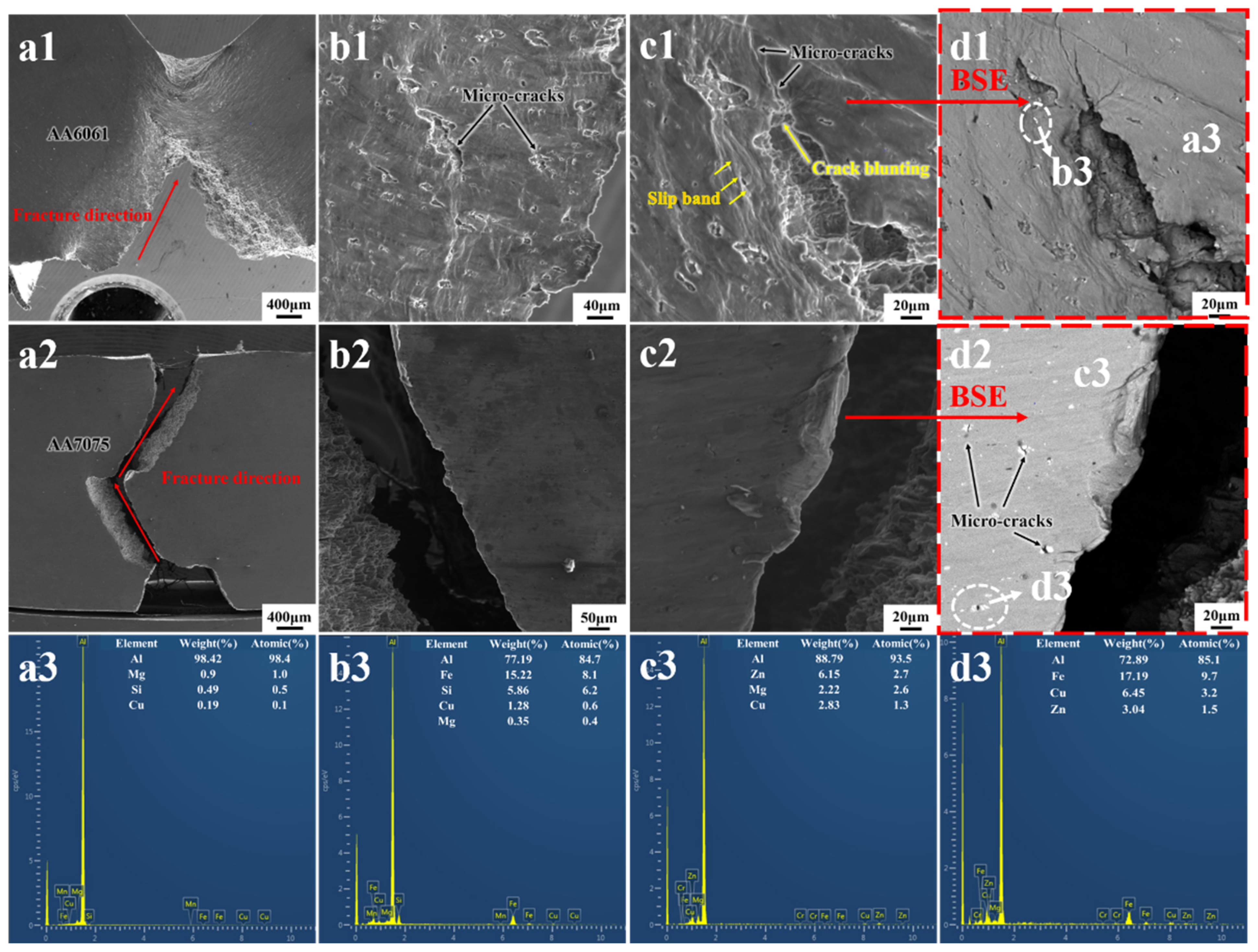
3.2. Effect on Microstructure of Composite Sheet

Figure 3a–c show the macroscopic interface morphologies of the AA6061/AA7075 composite sheets with the different thickness ratios and the orientation distribution function (ODF) diagram of the corresponding area. Figure 4a,b show the histograms of the strength of each component depicted in Figure 3. At the same position in the different samples, there are differences in the strength of each texture of the component metals. Due to the different flow characteristics of the component metals, the rheological stresses at the layer interface cause the AA6061 and AA7075 layers near the interface to mainly exhibit texture deformation. As shown in Figure 3, S (123) <634> texture, Dillamore (4 4 11) <11 11 8> texture, and brass (110) <112> texture are the main texture types. In addition, compared to that of the two samples of H6061:H7075, with thickness ratios of 3:1 and 1:2, the sample with a thickness ratio of 1.35:1 exhibits the highest strength of each deformed texture component of the composite sheet component metals, indicating that the closer the thickness ratio of the composite sheet component layer is to 1:1, the more obvious the interaction of the component metal near the interface and the higher the deformation texture strength provided.

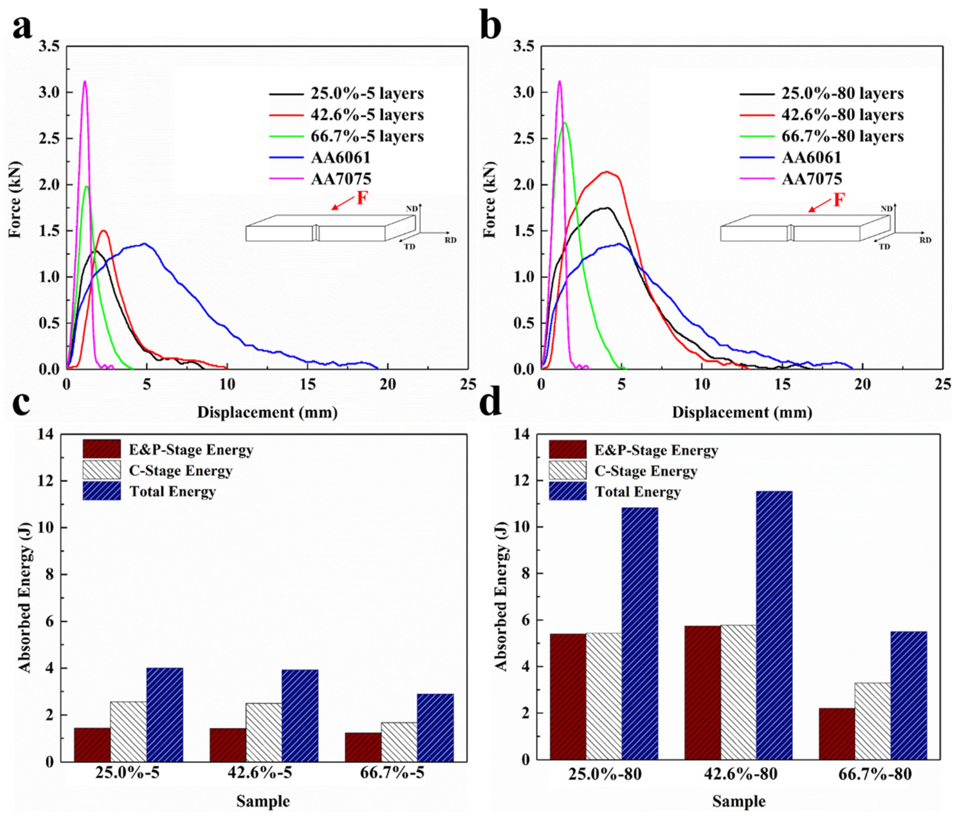
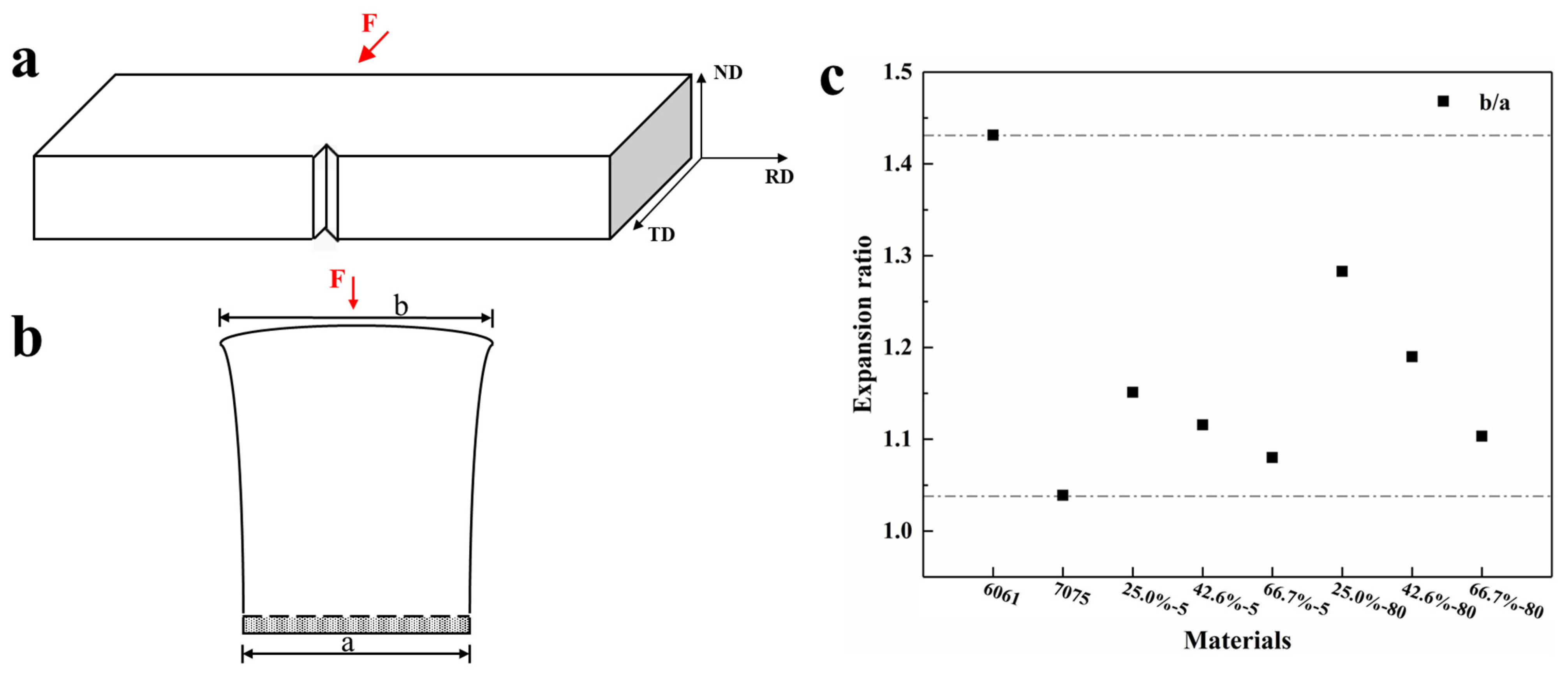
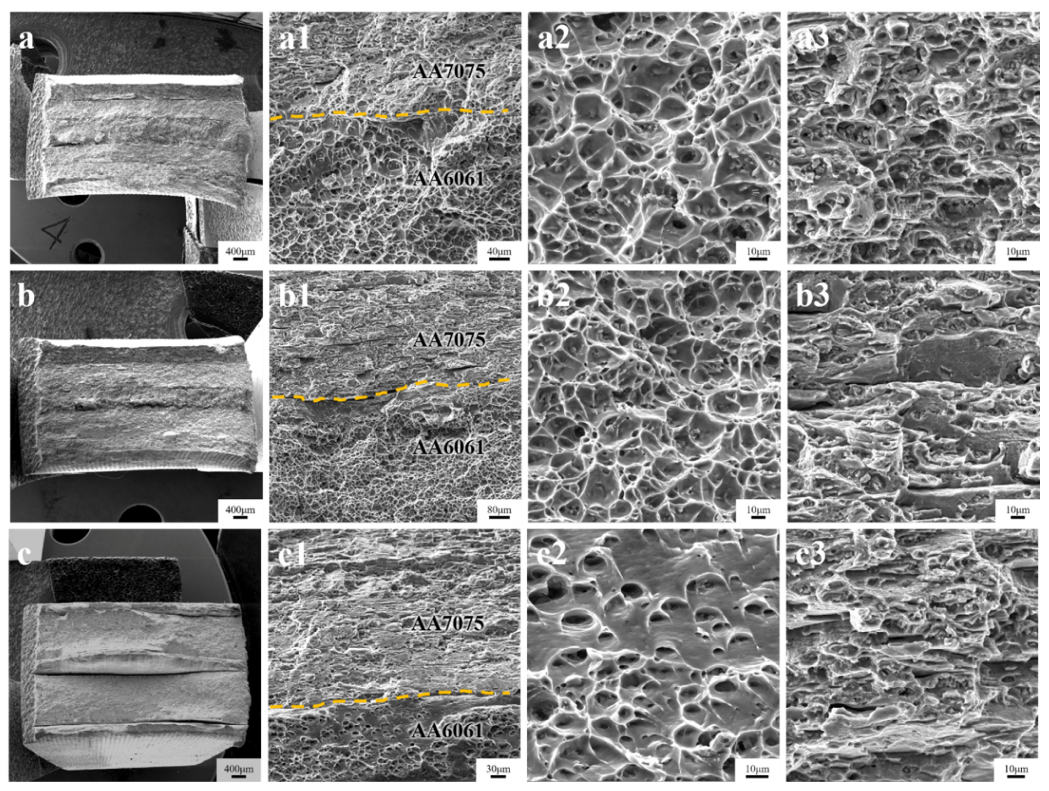
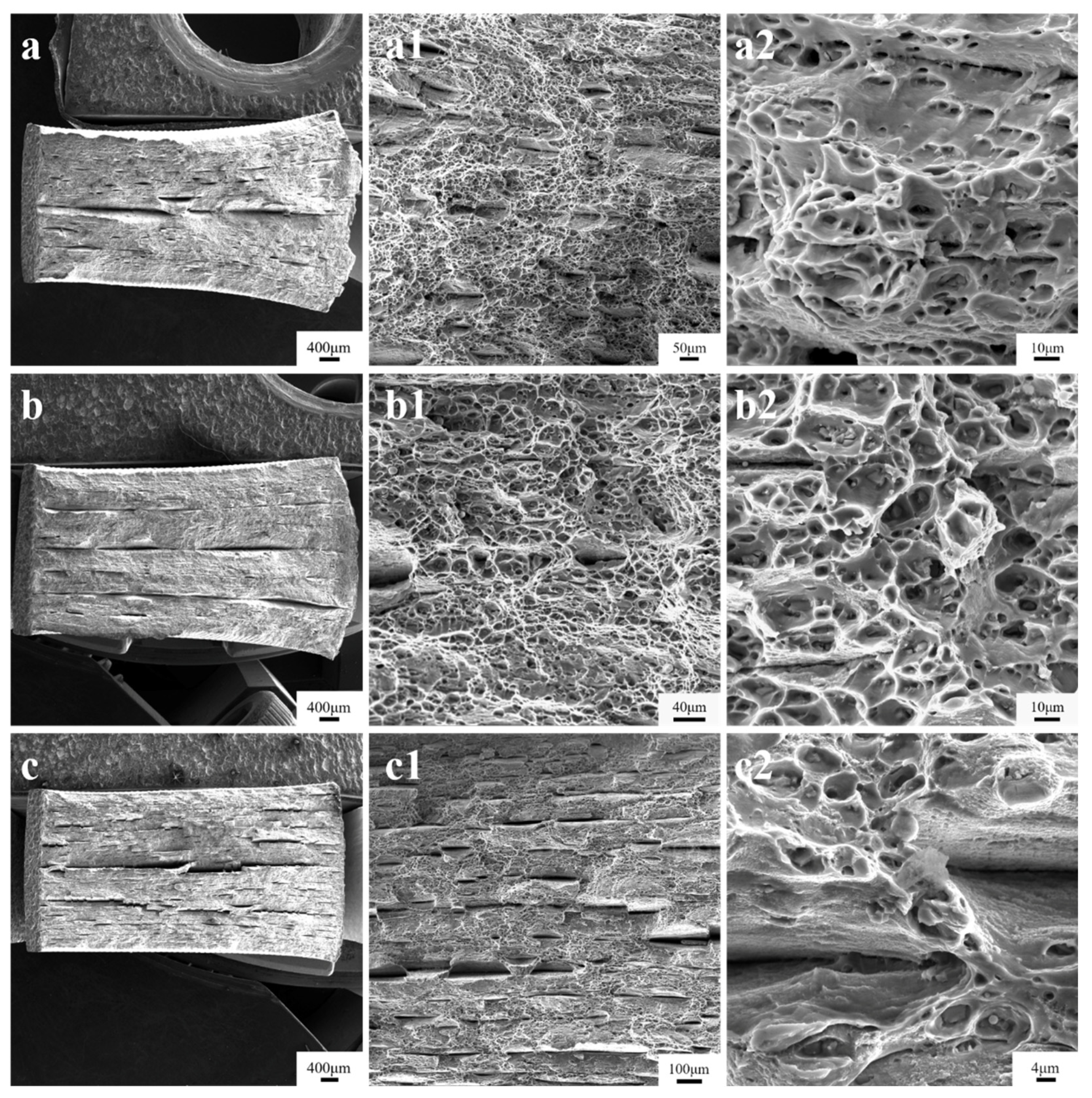
3.3. Effect on Impact Performance

The fracture process when a material is subjected to bending and impact loads usually consists of the following stages, namely, elastic deformation, plastic deformation, crack formation, and crack propagation. As shown in Figure 5, for the convenience of study, we divide the fracture process of the material into two major stages, which are the elastic and plastic deformation stage (E&P stage) and the crack initiation propagation stage (C stage). The energy consumed during the deformation process in the elastic and plastic deformation stage is expressed by WE&P, and, similarly, the energy consumed in the crack initiation propagation stage is WC, and, obviously, the total energy (WT) consumed in the whole process is the sum of the previous two, namely, WT = WE&P + WC.
Figure 6 shows the schematic diagram of the frontal impact, load-displacement curve, and energy absorbed in each deformation stage of the 5-layer and 80-layer samples. Compared to single sheets of AA6061 and AA7075, the AA6061/AA7075 composite sheets combine the performance of both materials. The AA6061/AA7075 composite sheets can not only withstand higher impact loads than AA6061 but also achieve a higher impact toughness than AA7075. Comparing the frontal impact curves of the 5- and 80-layer composite sheets, the increase in the number of layers of composite sheets, i.e., the increase in the number of layer interfaces, results in an improvement in the impact resistance of the composite sheets. This occurs because when a crack expands to the interface, on the one hand, it is horizontally deflected along the interface direction (RD), while on the other hand, when the crack expands along the vertical interface direction (ND) to the new component layer, a new small crack must be formed. Hence, the crack grows and expands to the next layer interface, leading to repeated sheet fracturing. The impact fracture curve indicates that the impact load Fm of a single AA7075 aluminum alloy sheet is the highest, and the Fm value of the composite sheet should increase with the increasing proportion of the AA7075 layers, but this is not the case. In the frontal impact process, the AA7075 composite sheet with a high thickness ratio (1:2) achieves a higher Fm value than the AA7075 composite sheet with the same thickness ratio (1.35:1), and this phenomenon is shown in Figure 6. As shown in Figure 6c,d, the 80-layer composite sheets exhibit higher impact work than the 5-layer composite sheets. The “interface pre layering” mechanism is the main reason for the significant improvement in the toughness of the composite sheets. Before the main crack reaches the interface, the composite sheet interface is peeled off, thus ensuring interface layering. Moreover, the crack re-forming nucleus after the interface is one of the reasons for the improvement in the toughness of the composite sheets.
Lateral scanning images of the morphology of the initial specimen after frontal impact are shown in Figure 7, indicating that under the action of the frontal impact load, the AA7075 specimen is completely fractured, and crack deflection occurs at the middle of the specimen. The AA6061 specimen is not completely fractured, the crack is tear-like, and there are more microcracks near the main crack. The deflection of cracks and the generation of microcracks cause an increase in the total length of cracks, which is conducive to improving the impact resistance of the material. To study the influence of the second-phase particles distributed in the sample matrix on crack germination and expansion, the AA6061 and AA7075 samples after impact were analyzed via energy-dispersive X-ray spectroscopy (EDS), as shown in Figure 7(d2). The germination and rapid expansion of internal cracks in the AA7075 aluminum alloy are related to the occurrence of many larger-sized second-phase particles in AA7075, and these large-sized second-phase particles not being effectively dissolved during solid solution treatment are mainly formed in the casting process. When the material is rolled and deformed, the second phase is broken into a certain aggregate state [39,40].
The EDS results (Figure 7(c3,d3)) show that the AA7075 matrix elements are mainly Al, Zn, Mg, and Cu, and the second-phase elements are mainly Al, Fe, and Cu, indicating that the second phase in the alloy may comprise Al2Cu, Al3Fe, Al7Cu2Fe, Al23CuFe4, etc. [41]. As shown in Figure 7(d2), cracks are more likely to form near the second-phase particles when subjected to external loads, and then rapidly spread to become connected, resulting in the rapid fracturing of the AA7075 aluminum alloy. Although there are also second-phase particles produced by Fe and Cu enrichment in the AA6061 matrix (Figure 7(d1)), the size is small, and these particles are dispersed, so the impact on the fracture performance of the sheet is relatively limited.
Figure 8 shows the SEM images of the morphology of the 5-layer composite sheets after the frontal impact. The figure reveals that in the 5-layer composite sheets with the different thickness ratios, the impact cracks are deflected when they extend to the interface, but there are differences in the crack direction among the samples with the different thickness ratios. In the AA7075 sheet with a small thickness, as shown in Figure 8(a1,a2), the crack continues to expand deep into the sheet after a certain deflection occurs at the interface, while in the sheet with a thickness ratio of 1:2, the crack expands along the interface direction after deflection, which is also the main reason for the low impact load.
Figure 9 shows the SEM images of the morphology of the 80-layer composite sheet after the frontal impact. Figure 9(b1–c1,b3–c3) show that compared to the impact crack expansion behavior of the 5-layer composite sheet, the crack in the 80-layer composite sheet deviates from the longitudinal motion plane several times, which functions as a toughening mechanism for improving the fracture toughness of the material. Under impact loading, cracks in the 80-layer specimen are deflected along the interface when they reach the compression side, which is manifested as typical S-curve characteristics. As shown in Figure 9(d2), new fine cracks can also induce the formation of fine cracks near the oxide layer in the matrix.
Figure 10 shows the schematic diagram of the lateral impact, load-displacement curve, and energy absorbed in each deformation stage of the 5-layer and 80-layer samples. Comparing the side impact curves of the 5- and 80-layer sheets, the increase in the number of layers not only improves the impact load that can be borne by the composite sheet but also increases the corresponding displacement when the material is completely fractured, which greatly improves the impact toughness of the sheet. Regarding the composite sheets with the same number of layers, the higher the proportion of AA7075 layers is, the higher the impact load it can withstand. For composite sheets with the same thickness ratio but different numbers of layers, with increasing number of layers, the fine crystal and interface strengthening effects increase, and these two strengthening mechanisms are the main reasons for the improvement in the material strength [27,42].
Figure 11a–c show schematics of the side impact and expansion ratio of the side impact of the different samples, respectively. Figure 12 shows the macroscopic fracture and local enlargement of the side impact specimen. As shown in the figure, the specimens after the side impact are completely fractured. The macroscopic fracture of the AA6061 single-layer sheet after impact reveals that this specimen experienced a high degree of plastic deformation, and the ND surface was very curved, showing a fan-shaped expansion along the direction of the impact transmission. Figure 12b shows the macroscopic fracture of the AA7075 single-layer sheet after impact. The widths of the front and back sides of the AA7075 specimen after impact are approximately the same, the section is straight, the degree of bending is low, and the lateral expansion value is very small, which indicates that the plastic deformation of the specimen is very small. In addition, the local enlargement of the fracture shows that the AA6061 fracture state is large, with small ligaments, small cavities, and fewer tearing edges. The AA7075 fracture morphology shows the characteristics of holes, dissociation river patterns, and many tearing edges because when the material is subjected to external loads, the deformation area occurs because of the accumulation of dislocation slips. In addition, because the impact specimen is subjected to solid solution strengthening treatment, holes can form near the strengthening phase in the substrate. Holes can also be created near the inclusions formed by oxide crushing at the interface in the roll bonding process, and these holes can subsequently become the source of cracks. Moreover, cracks can become connected and can eventually form microporous aggregation fractures. The AA7075 aluminum alloy contains many reinforced phase particles, which function as crack sources when subjected to external loads. In addition, the presence of small, reinforced phase particles causes the crack to deviate from the crystalline plane during expansion. When the crack expands within a grain, severe plastic deformation occurs at the grain boundary under lattice distortion, a tearing edge is formed, and the material exhibits a quasi-cleavage fracture.
Figure 13 shows the morphology of the impact fracture on the side of the 5-layer composite sheet. Similar to the morphology of the tensile fracture, the AA6061 layer exhibits a ductile fracture, the AA7075 layer exhibits a brittle fracture, and the thickness of the AA6061 layer is relatively small, which is manifested as a shear ligament socket and severe interfacial separation.
Figure 14 shows the morphology of the impact fracture on the side of the 80-layer composite sheet. Compared to the 5-layer specimen with obvious interfacial layering, the stratification in the 80-layer specimen was not obvious, and the ligament distribution was more uniform. The figure reveals that the 80-layer specimen exhibited interfacial separation at many locations because the interfacial bond strength of the resulting sheet is the lowest when the last few stacking cycles are rolled, resulting in all samples preferentially cracking along the last 1–2 planes of the composite interface when subjected to side impact loads. In addition, the increase in the number of layers yields an even ligament distribution across the sample cross-section, improves the uniform deformation ability of the material, and increases the corresponding displacement when the specimen is completely fractured. In addition, the increase in the number of interfacial layers causes an increase in the number of small cracks distributed at the interface, so that the sheet can accommodate more impact work.

4. Conclusions

(1)
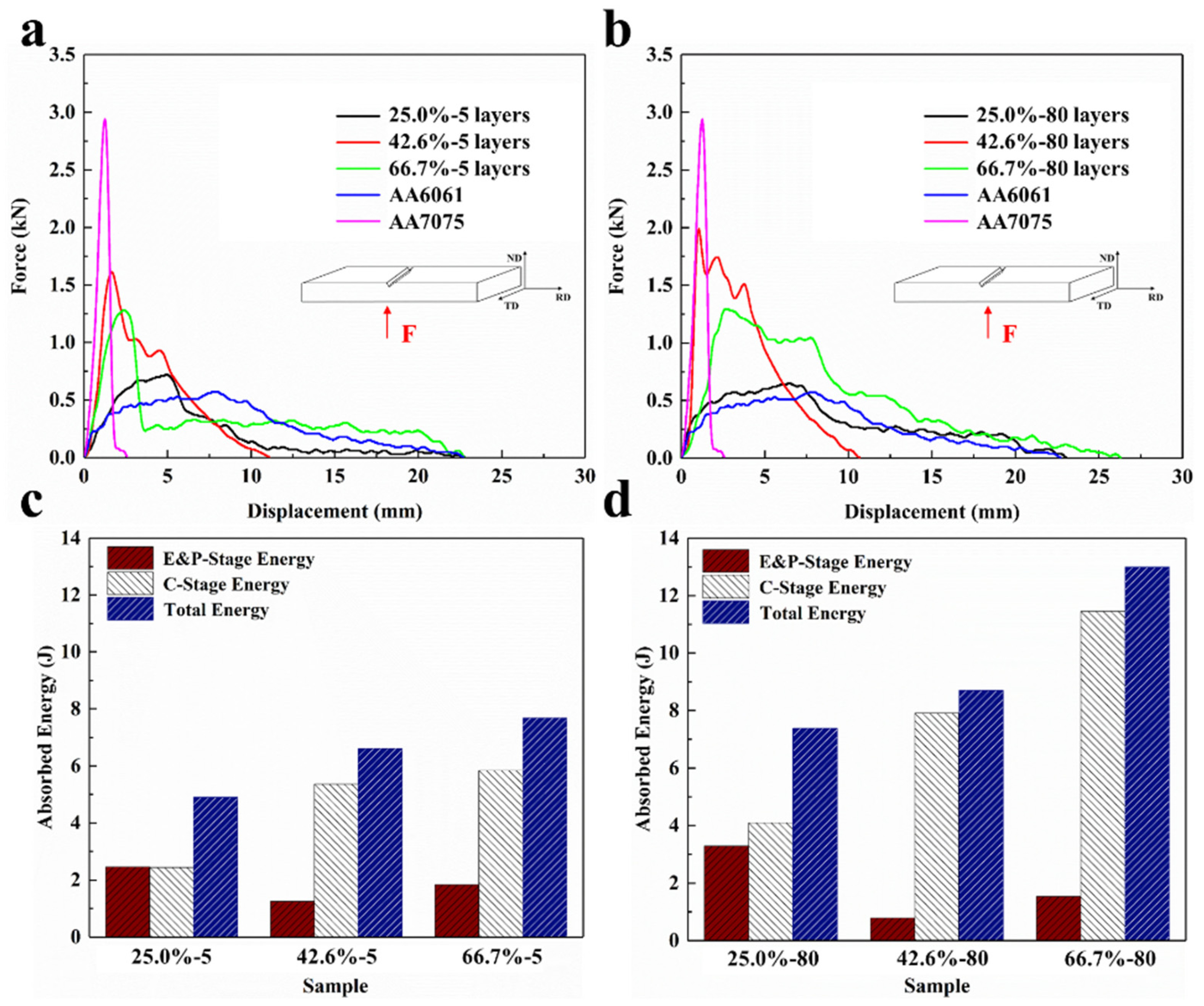
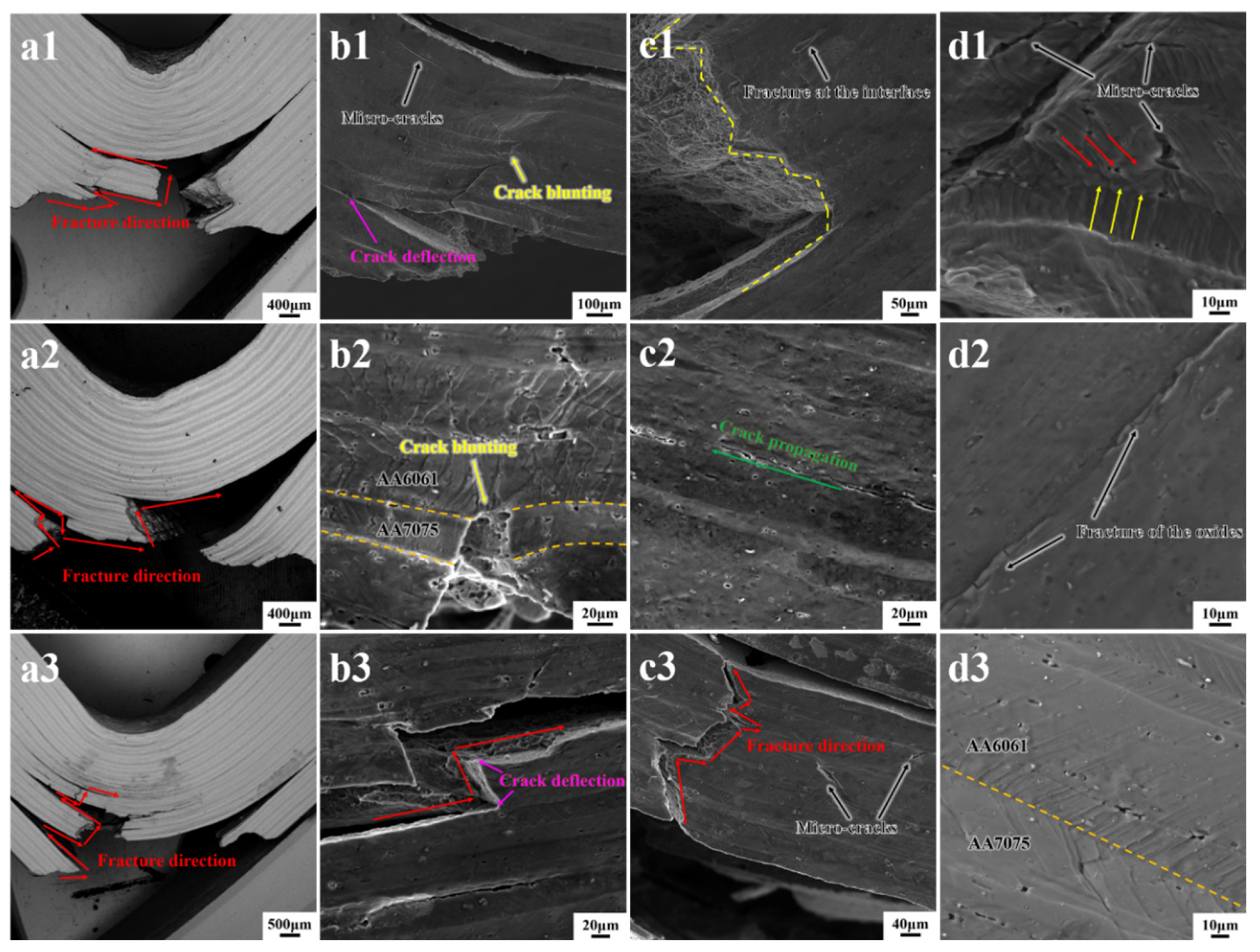
In the 5-layer composite sheet, the thickness ratio of the 1.35:1 samples can withstand a greater impact load than the thickness ratio of the 1:2 samples; this is because in the rapid impact load, the hard metal thickness of a high percentage of the 5-layer composite sheet in the crack is more likely to expand along the interface. In other words, the higher the proportion of AA7075, the higher the flexural strength of the AA6061/AA7075 laminated composite sheet.
(2)
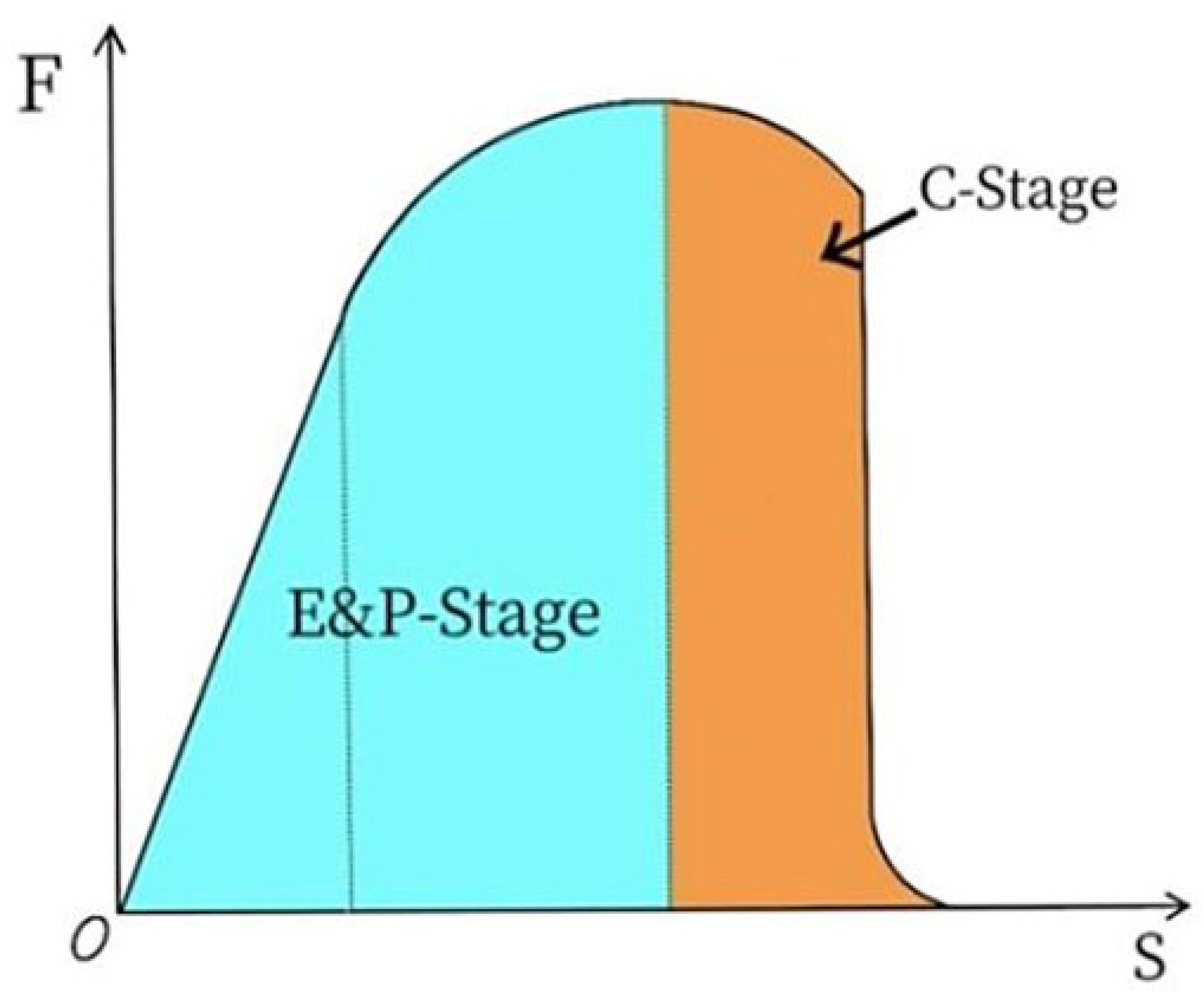
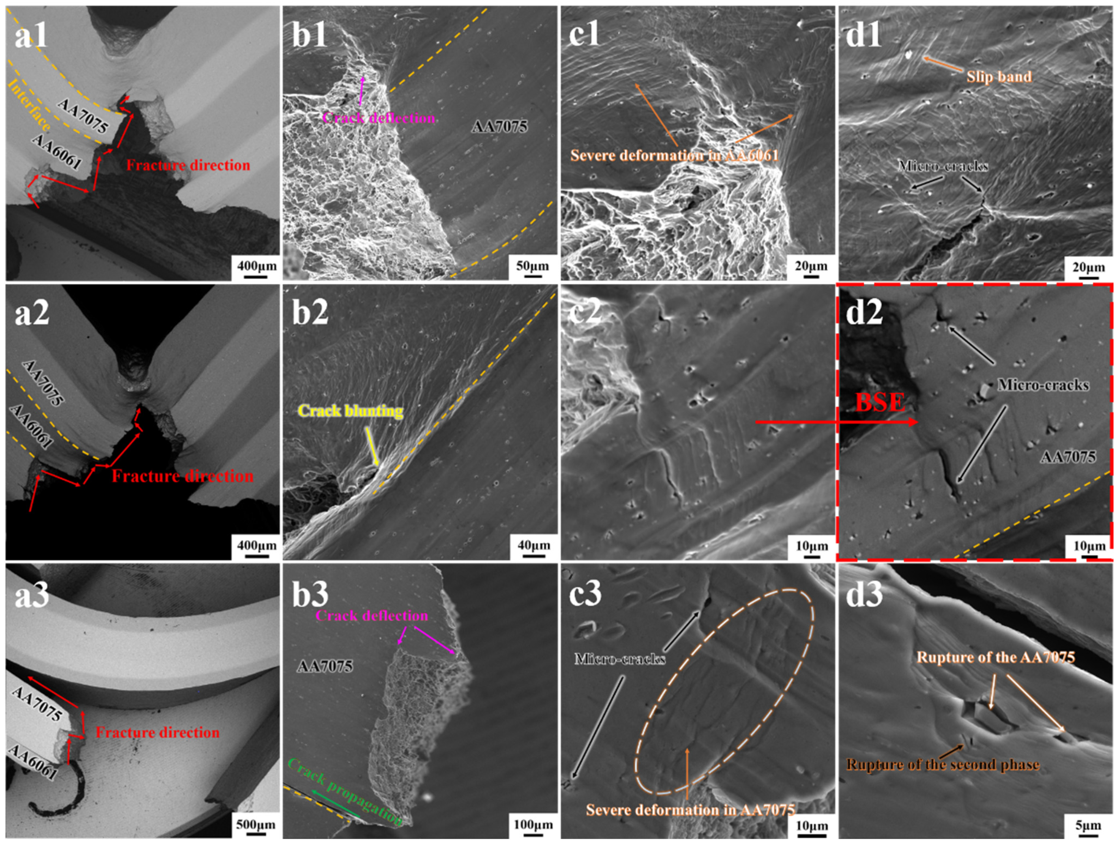
Compared with the 5-layer composite sheet, the toughening mechanism of the 80-layer composite sheet is mainly that the cracks deflect more frequently with the increase in the number of layers. In addition, the increase in the total crack length along the interface direction also promotes the change in the toughness of the composite sheet. The impact energy absorbed by the composite sheet increases with the increase in the number of layers, which is the same as the toughening effect of the sheet caused by the bending interface structure.
(3)
The increase in the number of layers significantly improves the side impact performance of the composite sheet. Fine crystal and interface strengthening effects work together to increase the impact strength and the energy absorbed at the crack germination and crack expansion stages of the 80-layer composite sheet relative to the 5-layer composite sheet.

Author Contributions

Conceptualization, Z.C. and G.L.; methodology, Z.C. and G.H.; validation, Y.C. and Z.C.; formal analysis, G.L., D.Z. and G.H.; investigation, Z.C., G.L. and D.Z.; resources, Y.C.; data curation, G.L. and D.Z.; writing—original draft preparation, G.L. and Y.C.; writing—review and editing, Z.C. and G.L.; supervision, Z.C. and Y.C.; project administration, Z.C. and Y.C., funding acquisition, Z.C. All authors have read and agreed to the published version of the manuscript.

Funding

This research was funded by the National Key Research and Development Program of China (Grant number 2021YFB3701301).

Data Availability Statement

Data are contained within the article.

Conflicts of Interest

The authors declare no conflict of interest.

References

  1. Shirvanimoghaddam, K.; Hamim, S.U.; Akbari, M.K.; Fakhrhoseini, S.M.; Khayyam, H.; Pakseresht, A.H.; Ghasali, E.; Zabet, M.; Munir, K.S.; Jia, S.; et al. Carbon fiber reinforced metal matrix composites: Fabrication processes and properties. Compos. Part A-Appl. 2017, 92, 70–96. [Google Scholar] [CrossRef]
  2. Chawla, N.; Shen, Y.L. Mechanical behavior of particle reinforced metal matrix composites. Adv. Eng. Mater. 2001, 3, 357–370. [Google Scholar] [CrossRef]
  3. Barabash, R.I.; Barabash, O.M.; Ojima, M.; Yu, Z.; Inoue, J.; Nambu, S.; Koseki, T.; Xu, R.; Feng, Z. Interphase strain gradients in multilayered steel composite from microdiffraction. Metall. Mater. Trans. A 2014, 45, 98–108. [Google Scholar] [CrossRef]
  4. Huang, M.; Xu, C.; Fan, G.; Maawad, E.; Gan, W.; Geng, L.; Lin, F.; Tang, G.; Wu, H.; Du, Y.; et al. Role of layered structure in ductility improvement of layered Ti-Al metal composite. Acta Mater. 2018, 153, 235–249. [Google Scholar] [CrossRef]
  5. Ma, X.; Huang, C.; Moering, J.; Ruppert, M.; Höppel, H.W.; Göken, M.; Narayan, J.; Zhu, Y. Mechanical properties of copper/bronze laminates: Role of interfaces. Acta Mater. 2016, 116, 43–52. [Google Scholar] [CrossRef]
  6. Wang, S.; Huang, L.; Jiang, S.; Zhang, R.; Sun, F.B.; An, Q.; Geng, L. Multiplied bending ductility and toughness of titanium matrix composites by laminated structure manipulation. Mater. Des. 2021, 197, 109237. [Google Scholar] [CrossRef]
  7. Alireza, A.; Iman, E.; Mehdi, R.; Navid, S. Laminated steel/aluminum composites: Improvement of mechanical properties by annealing treatment. Mater. Today Commun. 2021, 102866, 2352–4928. [Google Scholar]
  8. Kim, W.; Lee, T.; Han, S. Multi-layer graphene/copper composites: Preparation using high-ratio differential speed rolling, microstructure and mechanical properties. Carbon 2014, 69, 55–65. [Google Scholar] [CrossRef]
  9. Rohatgi, A.; Vecchio, K.S.; Gray, G.T. The influence of stacking fault energy on the mechanical behavior of Cu and Cu-Al alloys: Deformation twinning, work hardening, and dynamic recovery. Metall. Mater. Trans. A 2001, 32, 135–145. [Google Scholar] [CrossRef]
  10. Kim, I.K.; Hong, S.I. Effect of heat treatment on the bending behavior of tri-layered Cu/Al/Cu composite plates. Mater. Des. 2013, 47, 590–598. [Google Scholar] [CrossRef]
  11. Liu, J.; Wu, J.; Liu, Q.; Ji, S.; Zheng, X.; Wang, F.; Wang, J. Effect of the strength of initial aluminium on the bonding properties and deformation coordination of Ti/Al composite sheets by the cold roll bonding process. Crystals 2022, 12, 1665. [Google Scholar] [CrossRef]
  12. Chen, W.; He, W.; Chen, Z.; Jiang, B.; Liu, Q. Extraordinary room temperature tensile ductility of laminated Ti/Al composite: Roles of anisotropy and strain rate sensitivity. Int. J. Plast. 2020, 133, 102806. [Google Scholar] [CrossRef]
  13. Chen, W.; He, W.; Luo, N.; Tang, Y.; Chen, Z.; Jiang, B. Effect of layer thickness on the enhanced strength and ductility of laminated Ti/Al composite. Mater. Sci. Eng. A 2022, 859, 144230. [Google Scholar] [CrossRef]
  14. Luo, J.; Khattinejad, R.; Assari, A.; Tayyebi, M.; Hamawandi, B. Microstructure, mechanical and thermal properties of Al/Cu/Sic laminated composites, fabricated by the ARB and CARB processes. Crystals 2023, 13, 354. [Google Scholar] [CrossRef]
  15. Shabani, A.; Toroghinejad, M.R.; Shafyei, A. Fabrication of Al/Ni/Cu composite by accumulative roll bonding and electroplating processes and investigation of its microstructure and mechanical properties. Mater. Sci. Eng. A 2012, 558, 386–393. [Google Scholar] [CrossRef]
  16. Demkowicz, M.; Hoagland, R.; Hirth, J. Interface structure and radiation damage resistance in Cu-Nb multilayer nanocomposites. Phys. Rev. Lett. 2008, 100, 136102. [Google Scholar] [CrossRef] [PubMed]
  17. Shirakata, Y.; Hidaka, N.; Ishitsuka, M.; Teramoto, A.; Ohmi, T. High permeability and low loss Ni–Fe composite material for high-frequency applications. IEEE Trans. Magn. 2008, 44, 2100–2106. [Google Scholar] [CrossRef]
  18. Reddy, M.; Sharma, N.; Adams, S.; Rao, R.P.; Peterson, V.K.; Chowdari, B.V.R. Evaluation of undoped and M-doped TiO2, where M = Sn, Fe, Ni/Nb, Zr, V, and Mn, for lithium-ion battery applications prepared by the molten-salt method. Rsc Adv. 2015, 5, 29535–29544. [Google Scholar] [CrossRef]
  19. Mo, T.; Chen, Z.; Huang, H.; Lin, J.; Liu, Q. Effect of two-step annealing on recrystallized structure and mechanical properties in AA7075/AA1100 laminated metal composites processed by accumulative roll bonding. Mater. Charact. 2019, 158, 109951. [Google Scholar] [CrossRef]
  20. Woodward, R.L.; Cimpoeru, S.J. A study of the perforation of aluminium laminate targets. Int. J. Impact Eng. 1998, 21, 117–131. [Google Scholar] [CrossRef]
  21. Flores-Johnson, E.A.; Saleh, M.; Edwards, L. Ballistic performance of multi-layered metallic plates impacted by a 7.62-mm APM2 projectile. Int. J. Impact Eng. 2011, 38, 1022–1032. [Google Scholar] [CrossRef]
  22. Mo, T.; Chen, Z.; Zhou, D.; Lu, G.; Huang, Y.; Liu, Q. Effect of lamellar structural parameters on the bending fracture behavior of AA1100/AA7075 laminated metal composites. J. Mater. Sci. Technol. 2022, 99, 28–38. [Google Scholar] [CrossRef]
  23. Gomez, X.; Echeberria, J. Microstructure and mechanical properties of carbon steel A210–superalloy Sanicro 28 bimetallic tubes. Mater. Sci. Eng. A 2003, 348, 180–191. [Google Scholar] [CrossRef]
  24. Knight, S.P.; Birbilis, N.; Muddle, B.C.; Trueman, A.R.; Lynch, S.P. Correlations between intergranular stress corrosion cracking, grain-boundary microchemistry, and grain-boundary electrochemistry for Al–Zn–Mg–Cu alloys. Corros. Sci. 2010, 52, 4073–4080. [Google Scholar] [CrossRef]
  25. Ma, G.Y.; Luo, X.Z.; Liu, D.H.; Jia, C.; Niu, F.Y.; Wu, D.J. 7075 Aluminum alloy welded by laser-TIG hybrid with homogeneous filler wire: Microstructure evaluation and molten pool behavior. Opt. Laser Technol. 2024, 169, 110059. [Google Scholar] [CrossRef]
  26. Harsha, V.T.; Varikuppala, P.K.; Yadav, G.T.; Bandhavi, C. Experimental investigation and optimization of Aluminium 6061 by using various welding process—A review. Mater. Today Proc. 2023, 95, 2214–7853. [Google Scholar]
  27. Frutos, J.A.; Ambriz, R.R.; García, C.J.; Jaramillo, D. Orthogonal impact load in 6061-T651 and 7075-T651 aluminum alloy plates. J. Mater. Res. Technol. 2023, 26, 4245–4262. [Google Scholar] [CrossRef]
  28. Yazar, Ö.; Ediz, T.; Öztürk, T. Control of macrostructure in deformation processing of metal/metal laminates. Acta Mater. 2005, 53, 375–381. [Google Scholar] [CrossRef]
  29. Lee, J.M.; Lee, B.R.; Kang, S.B. Control of layer continuity in metallic multilayers produced by deformation synthesis method. Mater. Sci. Eng. A 2005, 406, 95–101. [Google Scholar] [CrossRef]
  30. Ebrahimi, M.; Wang, Q. Accumulative roll-bonding of aluminum alloys and composites: An overview of properties and performance. J. Mater. Res. Technol. 2002, 19, 4381–4403. [Google Scholar] [CrossRef]
  31. Chen, Z.J.; Liu, Q.; Wang, G.J. Deformation inhomogeneities of Mg–Al laminated metal composites fabricated by accumulative roll bonding. Mater. Res. Innov. 2015, 19, S147–S151. [Google Scholar] [CrossRef]
  32. Kılıçaslan, C.; Güden, M.; Odacı, İ.K. Experimental and numerical studies on the quasi-static and dynamic crushing responses of multi-layer trapezoidal aluminum corrugated sandwiches. Thin-Walled Struct. 2014, 78, 70–78. [Google Scholar] [CrossRef]
  33. Cepeda, J.C.; Hidalgo, P.; Pozuelo, M.; Ruano, O.A.; Carreño, F. Influence of constituent materials on the impact toughness and fracture mechanisms of hot-roll-bonded aluminum multilayer laminates. Metall. Mater. Trans. A 2010, 41, 61–72. [Google Scholar] [CrossRef]
  34. Cepeda-Jiménez, C.; Pozuelo, M.; García-Infanta, J.; Ruano, O.A.; Carreño, F. Interface effects on the fracture mechanism of a high-toughness aluminum-composite laminate. Metall. Mater. Trans. A 2009, 40, 69–79. [Google Scholar] [CrossRef]
  35. Ibrahim, M.F.; Samuel, E.; Samuel, A.M. Impact toughness and fractography of Al–Si–Cu–Mg base alloys. Mater. Des. 2011, 32, 3900–3910. [Google Scholar] [CrossRef]
  36. Huang, C.; Wang, Y.; Ma, X.; Yin, S.; Höppel, H.W.; Göken, M.; Wu, X.L.; Gao, H.J.; Zhu, Y.T. Interface affected zone for optimal strength and ductility in heterogeneous laminate. Mater. Today 2018, 21, 713–719. [Google Scholar] [CrossRef]
  37. Sun, S.; Liu, P.; Hu, J.; Hong, C.; Qiao, X.; Liu, S.; Zhang, R.; Wu, C. Effect of solid solution plus double aging on microstructural characterization of 7075 Al alloys fabricated by selective laser melting (SLM). Opt. Laser Technol. 2019, 114, 158–163. [Google Scholar] [CrossRef]
  38. Reihanian, M.; Naseri, M. An analytical approach for necking and fracture of hard layer during accumulative roll bonding (ARB) of metallic multilayer. Mater. Des. 2016, 89, 1213–1222. [Google Scholar] [CrossRef]
  39. Xu, C.; Furukawa, M.; Horita, Z.; Langdon, T. Influence of ECAP on precipitate distributions in a spray-cast aluminum alloy. Acta Mater. 2005, 53, 749–758. [Google Scholar] [CrossRef]
  40. Roven, H.J.; Liu, M.; Werenskiold, J.C. Dynamic precipitation during severe plastic deformation of an Al–Mg–Si aluminium alloy. Mater. Sci. Eng. A 2008, 483, 54–58. [Google Scholar] [CrossRef]
  41. Clinch, M.; Harris, S.; Hepples, W.; Holroyd, N.J.H.; Lawday, M.J.; Noble, B. Influence of zinc to magnesium ratio and total solute content on the strength and toughness of 7xxx series alloys. Mater. Sci. Forum. 2006, 519–521, 339–344. [Google Scholar] [CrossRef]
  42. Cepeda-Jiménez, C.M.; Pozuelo, M.; Ruano, O.A.; Carreño, F. Influence of the thermomechanical processing on the fracture mechanisms of high strength aluminium/pure aluminium multilayer laminate materials. Mater. Sci. Eng. A 2008, 490, 319–327. [Google Scholar] [CrossRef]
Figure 1. Schematic diagram of laminated metal composite plate preparation.
Crystals 14 00044 g001
Figure 2. Interface morphology of the AA6061/AA7075 composite sheet under the different ARB cycles: the initial thickness ratios of AA6061 and AA7075 are 3:1 (a1e1), 1.35:1 (a2e2), and 1:2 (a3e3).
Crystals 14 00044 g002
Figure 3. SEM images and ODF distribution of the samples with the different thickness ratios (V6061:V7075): (a) 3:1; (b) 1.35:1; (c) 1:2.
Crystals 14 00044 g003
Figure 4. Summary of the strength of each texture component in the component layer: (a) AA6061 layer; (b) AA7075 layer.
Crystals 14 00044 g004
Figure 5. Impact load-displacement curve.
Crystals 14 00044 g005
Figure 6. Frontal impact curves and absorbed energies for different laminated metal composites: (a,c) 5 layers and (b,d) 80 layers.
Crystals 14 00044 g006
Figure 7. Lateral morphology and energy spectra of the initial material after frontal impact: (a1d1) AA6061; (a2d2) AA7075; (a3d3) EDS.
Crystals 14 00044 g007
Figure 8. SEM images after impact of 5-layer composites with the different thickness ratios (V6061:V7075): (a1d1) 3:1; (a2d2) 1.35:1; (a3d3) 1:2.
Crystals 14 00044 g008
Figure 9. SEM images after impact of 80-layer composites with the different thickness ratios (V6061:V7075): (a1d1) 3:1; (a2d2) 1.35:1; (a3d3) 1:2.
Crystals 14 00044 g009
Figure 10. Frontal impact curves and absorbed energies for different laminated metal composites: (a,c) 5 layers and (b,d) 80 layers.
Crystals 14 00044 g010
Figure 11. Schematic diagram of (a,b) the side impact and (c) side impact expansion ratio of the different samples.
Crystals 14 00044 g011
Figure 12. Side impact fracture morphology of the single material: (aa2) AA6061; (bb2) AA7075.
Crystals 14 00044 g012
Figure 13. Side impact fracture morphology of 5-layer composite sheet: (aa3) 3:1; (bb3) 1.35:1; (cc3) 1:2.
Crystals 14 00044 g013
Figure 14. Side impact fracture morphology of 80-layer composite sheet: (aa3) 3:1; (bb3) 1.35:1; (cc3) 1:2.
Crystals 14 00044 g014
Table 1. Chemical composition of the AA6061 and AA7075 alloy sheets (wt. %).
AlloyZnMgCuSiFeMnCrTiAl
AA6061<0.201.050.210.620.41<0.150.17≤0.10Bal.
AA70755.52.41.71.40.20.050.07Bal.
Table 2. Initial thickness ratio of AA6061 and AA7075 sheets.
Total Thickness Ratio (AA6061:AA7075)3:11.35:11:2
Single-layer thickness × Number of layers = Component thickness (mm)AA60612 × 3 = 61.8 × 3 = 5.41 × 3 = 3
AA70751 × 2 = 22 × 2 = 43 × 2 = 6
Volume proportion of AA7075 (%)25.042.666.7
Table 3. Property parameters of AA6061 and AA7075.
MaterialHardening IndexStrength Coefficient (MPa)Tensile Strength (MPa)Elongation
AA60610.28492.75254.780.25
AA70750.38982.40370.880.15
Disclaimer/Publisher’s Note: The statements, opinions and data contained in all publications are solely those of the individual author(s) and contributor(s) and not of MDPI and/or the editor(s). MDPI and/or the editor(s) disclaim responsibility for any injury to people or property resulting from any ideas, methods, instructions or products referred to in the content.

