


Effects of Different CO2 Concentrations and Degradation Media on Static Corrosion of Commercially Pure Zinc

 , and
, and
Abstract
1. Introduction
2. Materials and Methods
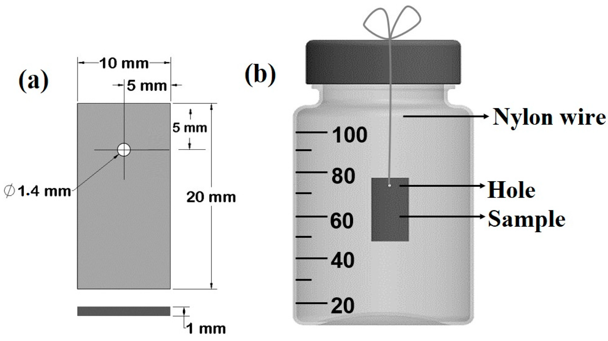
2.1. Samples Preparation
2.2. Static Degradation Immersion Test (SDIT)
2.2.1. Solution Preparation
2.2.2. Specimen Immersion
2.2.3. Sample Extraction and Waste Solution Management
2.2.4. Sample Digestion and Zn Solubility Assessment
2.3. Samples Characterization
3. Results
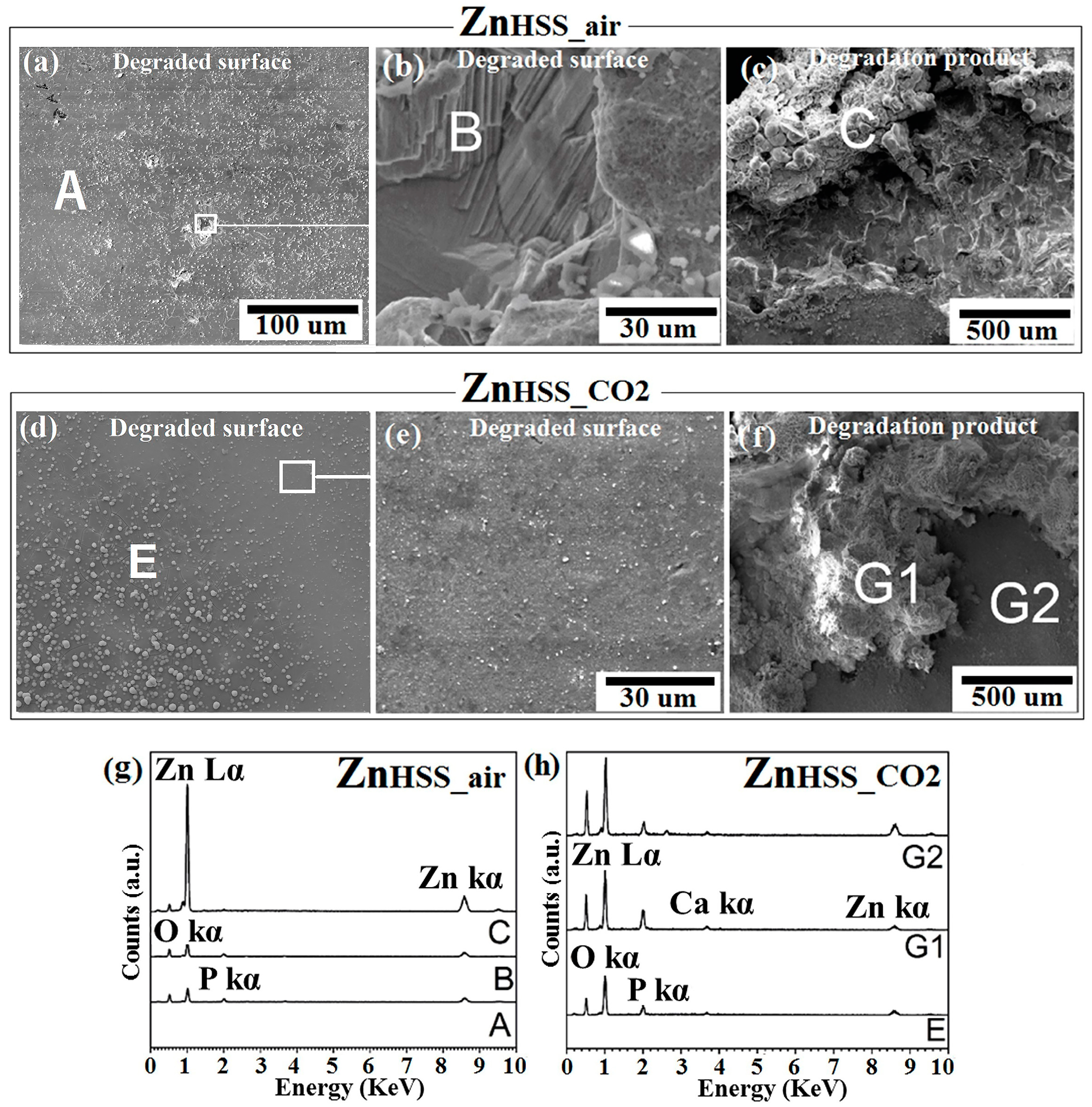
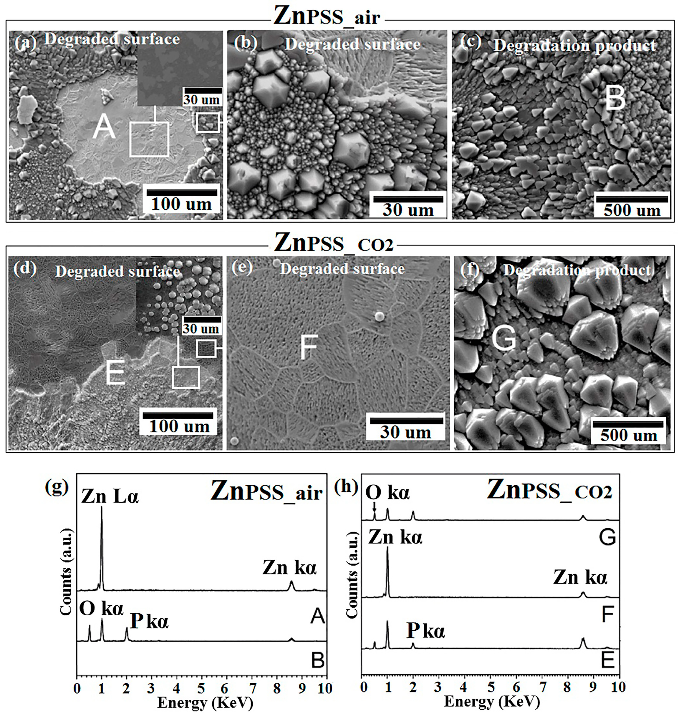
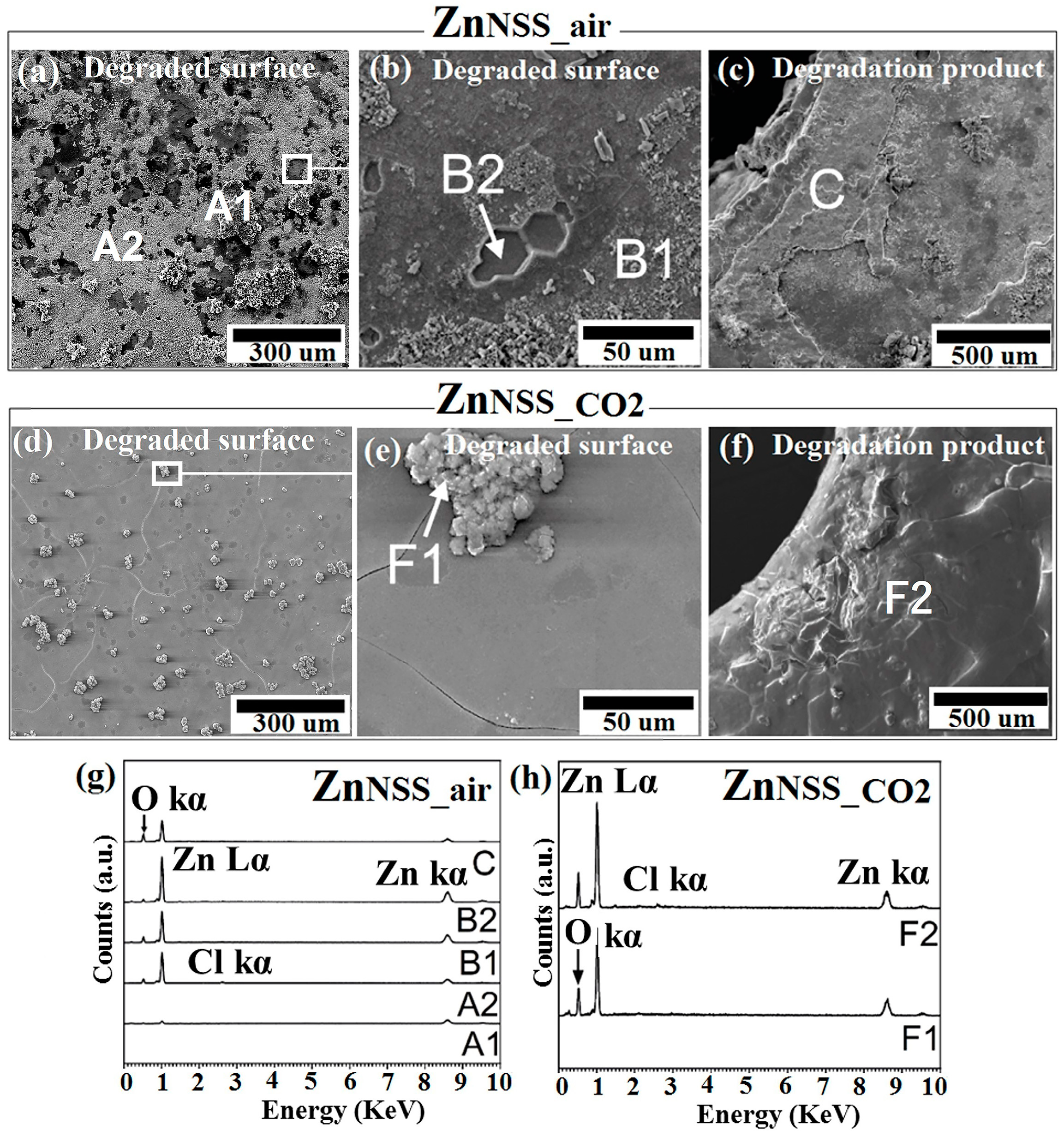
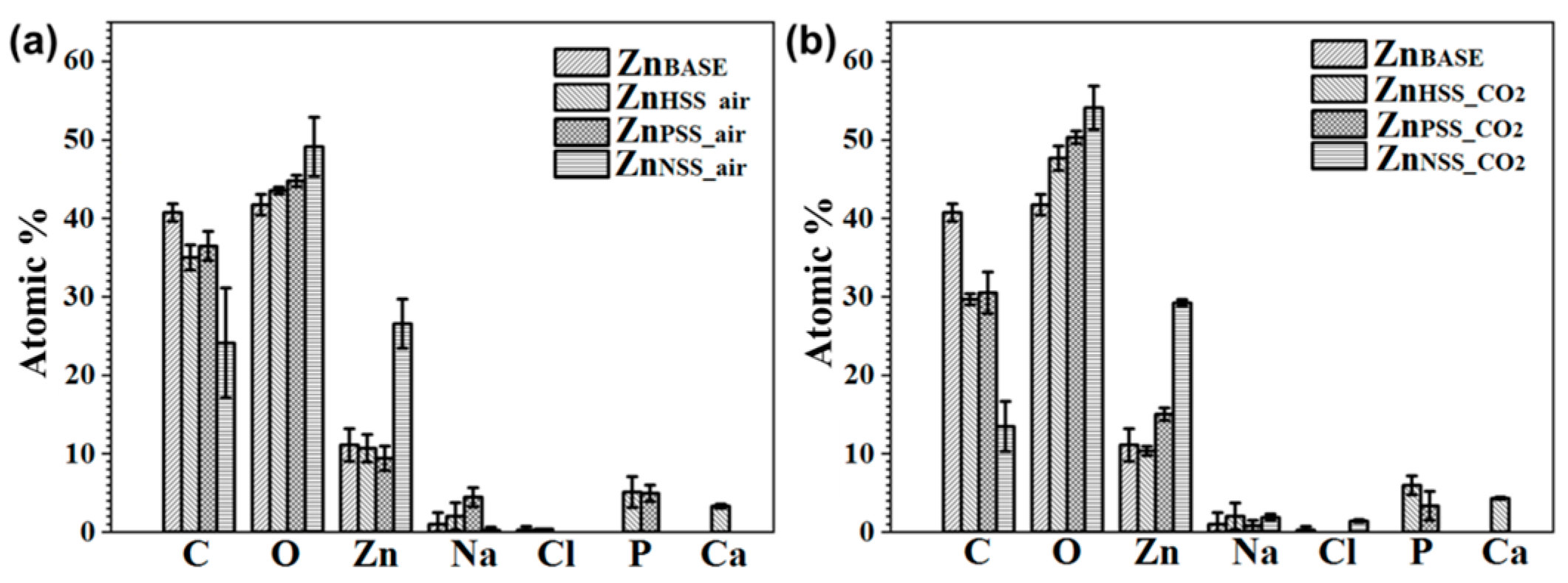
3.1. SEM-EDS Analysis
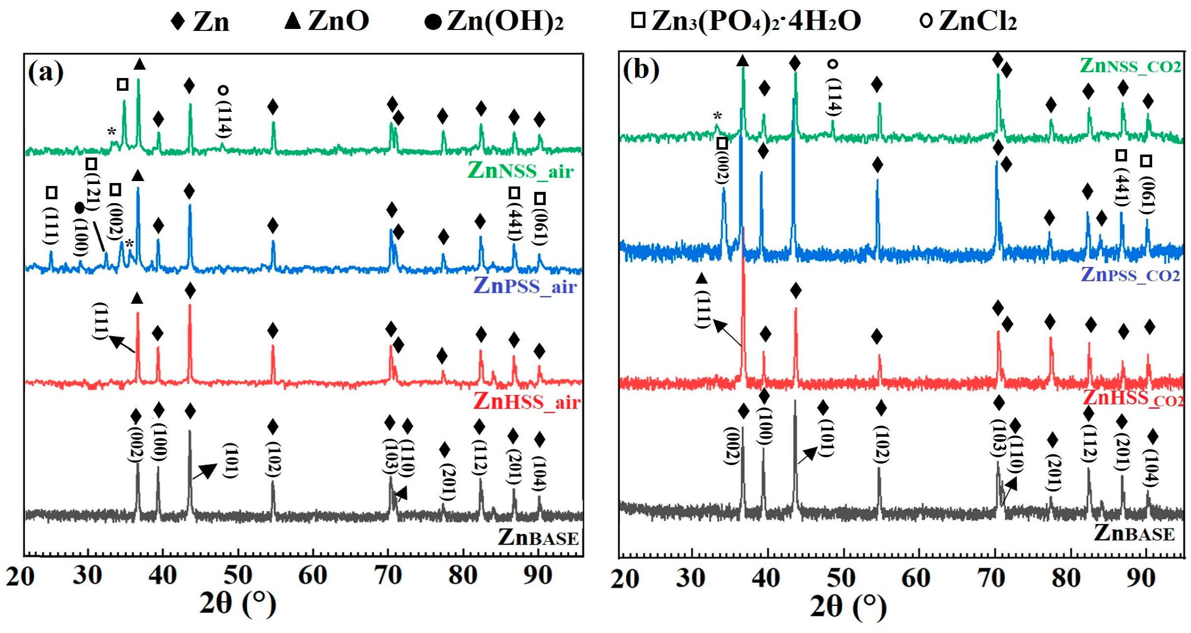
3.2. XRD Analysis
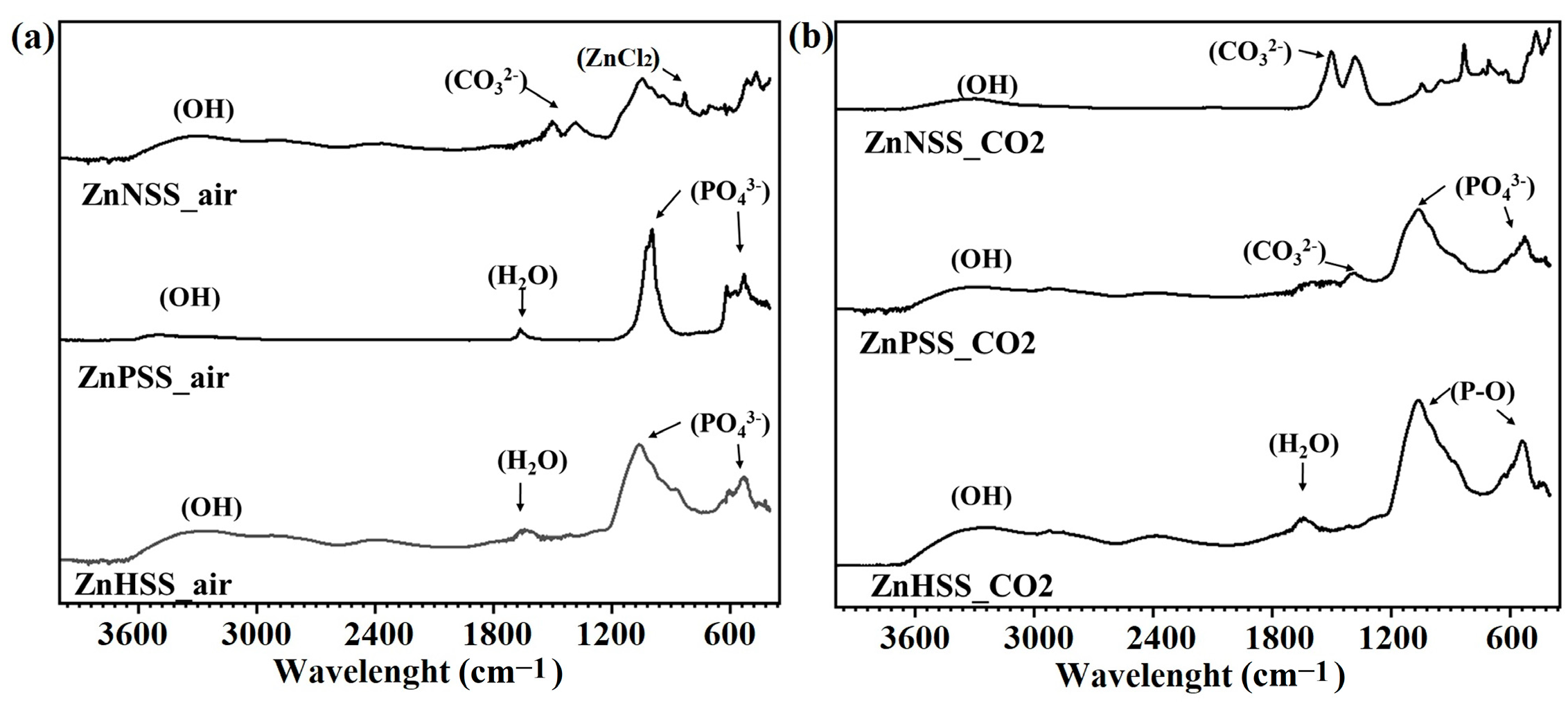
3.3. FTIR Analysis
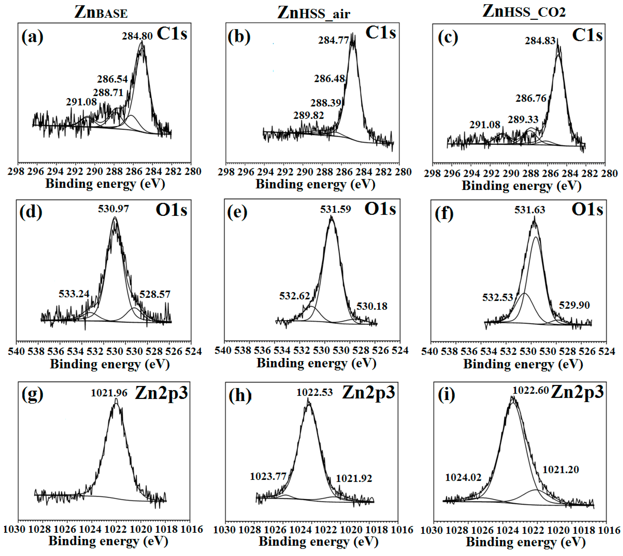
3.4. XPS Analysis
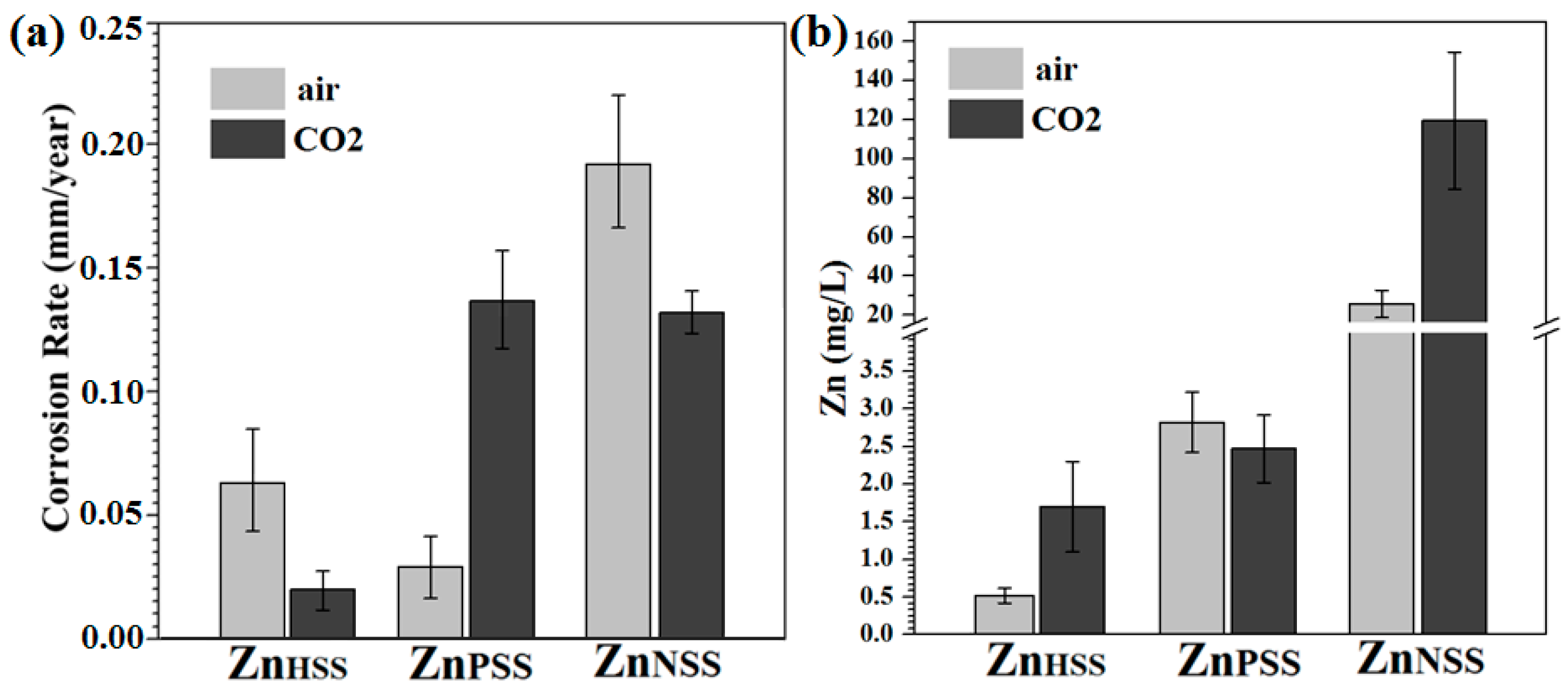
3.5. Corrosion Rate
4. Discussion
5. Conclusions
- (a)
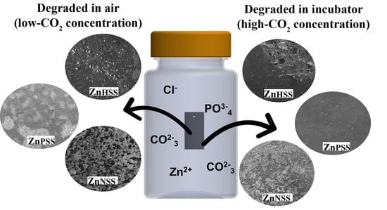
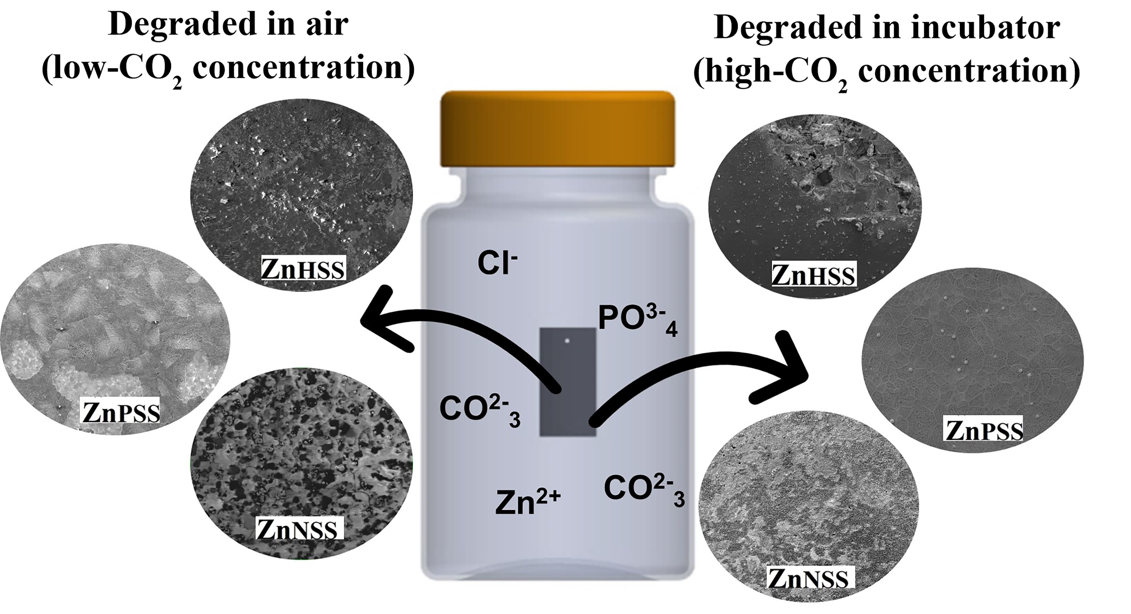
- ZnO or a mixed ZnO/Zn(OH)2 degradation layer with Zn3(PO4)2·4H2O and Zn(CO3)2 precipitates were found on surfaces immersed in both HSS and PSS, independently of the atmosphere;
- (b)
- A clear layer of crystallized Zn3(PO4)2·4H2O was detected just for the PSS condition;
- (c)
- A ZnO/ZnCl2 layer with amorphous carbonates precipitates was found on all surfaces immersed in NSS;
- (d)
- Samples tested under a CO2-rich atmosphere showed a more compact passivating layer, higher dimensions crystals and less cavities when tested in HSS, PSS and NSS, respectively, due to both buffering systems promoted by CO2(g) and the major protection contribution of carbonates;
- (e)
- The highest CR was observed for pure Zn tested in NSS under ambient conditions due to the attack of aggressive Cl− ions consuming the starting oxide/hydroxide degradation layer and the scarce protective contribution of the carbonates passivating layer.
Supplementary Materials
Author Contributions
Funding
Data Availability Statement
Conflicts of Interest
References
- Liu, Y.; Zheng, Y.; Chen, X.-H.; Yang, J.-A.; Pan, H.; Chen, D.; Wang, L.; Zhang, J.; Zhu, D.; Wu, S.; et al. Fundamental theory of biodegradable metals—Definition, criteria, and design. Adv. Funct. Mater. 2019, 29, 1805402. [Google Scholar] [CrossRef]
- Li, H.; Zheng, Y.; Qin, L. Progress of biodegradable metals. Progr. Nat. Sci. Mater. Intern. 2014, 24, 414–422. [Google Scholar] [CrossRef]
- Zheng, Y.; Gu, X.; Witte, F. Biodegradable metals. Mater. Sci. Eng. R Rep. 2014, 77, 1–34. [Google Scholar] [CrossRef]
- Schinhammer, M.; Hänzi, A.C.; Löffler, J.F.; Uggowitzer, P.J. Design strategy for biodegradable Fe-based alloys for medical applications☆. Acta Biomater. 2010, 6, 1705–1713. [Google Scholar] [CrossRef] [PubMed]
- Zhu, S.; Huang, N.; Xu, L.; Zhang, Y.; Liu, H.; Sun, H.; Leng, Y. Biocompatibility of pure iron: In vitro assessment of degradation kinetics and cytotoxicity on endothelial cells. Mater. Sci. Eng. C 2009, 29, 1589–1592. [Google Scholar] [CrossRef]
- Peuster, M. A novel approach to temporary stenting: Degradable cardiovascular stents produced from corrodible metal—results 6–18 months after implantation into New Zealand white rabbits. Heart 2001, 86, 563–569. [Google Scholar] [CrossRef]
- Zhang, E.; Chen, H.; Shen, F. Biocorrosion properties and blood and cell compatibility of pure iron as a biodegradable biomaterial. J. Mater. Sci. Mater. Med. 2010, 21, 2151–2163. [Google Scholar] [CrossRef]
- Hermawan, H.; Mantovani, D. Process of prototyping coronary stents from biodegradable Fe–Mn alloys. Acta Biomater. 2013, 9, 8585–8592. [Google Scholar] [CrossRef]
- Hermawan, H.; Purnama, A.; Dube, D.; Couet, J.; Mantovani, D. Fe–Mn alloys for metallic biodegradable stents: Degradation and cell viability studies☆. Acta Biomater. 2010, 6, 1852–1860. [Google Scholar] [CrossRef]
- Fiocchi, J.; Biffi, C.A.; Gambaro, S.; Paternoster, C.; Mantovani, D.; Tuissi, A. Effect of laser welding on the mechanical and degradation behaviour of Fe-20Mn-0.6C bioabsorbable alloy. J. Mater. Res. Technol. 2020, 9, 13474–13482. [Google Scholar] [CrossRef]
- Mouzou, E.; Paternoster, C.; Tolouei, R.; Chevallier, P.; Biffi, C.A.; Tuissi, A.; Mantovani, D. CO2-rich atmosphere strongly affects the degradation of Fe-21Mn-1C for biodegradable metallic implants. Mater. Lett. 2016, 181, 362–366. [Google Scholar] [CrossRef]
- Loffredo, S.; Gambaro, S.; Copes, F.; Paternoster, C.; Giguère, N.; Vedani, M.; Mantovani, D. Effect of silver in thermal treatments of Fe-Mn-C degradable metals: Implications for stent processing. Bioact. Mater. 2022, 12, 30–41. [Google Scholar] [CrossRef]
- Sikora-Jasinska, M.; Chevallier, P.; Turgeon, S.; Paternoster, C.; Mostaed, E.; Vedani, M.; Mantovani, D. Understanding the effect of the reinforcement addition on corrosion behavior of Fe/Mg2Si composites for biodegradable implant applications. Mater. Chem. Phys. 2019, 223, 771–778. [Google Scholar] [CrossRef]
- Loffredo, S.; Gambaro, S.; de Andrade, L.M.; Paternoster, C.; Casati, R.; Giguère, N.; Vedani, M.; Mantovani, D. Six-month long in vitro degradation tests of biodegradable twinning-induced plasticity steels alloyed with Ag for stent applications. ACS Biomater. Sci. Eng. 2021, 7, 3669–3682. [Google Scholar] [CrossRef]
- Wang, J.; Xu, J.; Hopkins, C.; Chow, D.H.; Qin, L. Biodegradable magnesium-based implants in orthopedics—A general review and perspectives. Adv. Sci. 2020, 7, 1902443. [Google Scholar] [CrossRef]
- Chen, Y.; Xu, Z.; Smith, C.; Sankar, J. Recent advances on the development of magnesium alloys for biodegradable implants. Acta Biomater. 2014, 10, 4561–4573. [Google Scholar] [CrossRef] [PubMed]
- Hartwig, A. Role of magnesium in genomic stability. Mutat. Res./Fund. Mol. Mech. Mutagen. 2001, 475, 113–121. [Google Scholar] [CrossRef]
- Zhang, Y.; Xu, J.; Ruan, Y.C.; Yu, M.K.; O’Laughlin, M.; Wise, H.; Chen, D.; Tian, L.; Shi, D.; Wang, J.; et al. Implant-derived magnesium induces local neuronal production of CGRP to improve bone-fracture healing in rats. Nat. Med. 2016, 22, 1160–1169. [Google Scholar] [CrossRef]
- Staiger, M.P.; Pietak, A.M.; Huadmai, J.; Dias, G. Magnesium and its alloys as orthopedic biomaterials: A review. Biomaterials 2006, 27, 1728–1734. [Google Scholar] [CrossRef]
- Sandlöbes, S.; Pei, Z.; Friák, M.; Zhu, L.-F.; Wang, F.; Zaefferer, S.; Raabe, D.; Neugebauer, J. Ductility improvement of Mg alloys by solid solution: Ab initio modeling, synthesis and mechanical properties. Acta Mater. 2014, 70, 92–104. [Google Scholar] [CrossRef]
- Zerankeshi, M.M.; Alizadeh, R.; Gerashi, E.; Asadollahi, M.; Langdon, T.G. Effects of heat treatment on the corrosion behavior and mechanical properties of biodegradable Mg alloys. J. Magn. All. 2022, 10, 1737–1785. [Google Scholar] [CrossRef]
- Xie, J.; Zhang, J.; You, Z.; Liu, S.; Guan, K.; Wu, R.; Wang, J.; Feng, J. Towards developing Mg alloys with simultaneously improved strength and corrosion resistance via RE alloying. J. Magn. All. 2021, 9, 41–56. [Google Scholar] [CrossRef]
- Tekumalla, S.; Seetharaman, S.; Almajid, A.; Gupta, M. Mechanical properties of magnesium-rare earth alloy systems: A review. Metals 2014, 5, 1–39. [Google Scholar] [CrossRef]
- Virtanen, S. Biodegradable Mg and Mg alloys: Corrosion and biocompatibility. Mater. Sci. Eng. B 2011, 176, 1600–1608. [Google Scholar] [CrossRef]
- Gambaro, S.; Nascimento, M.L.; Shekargoftar, M.; Ravanbakhsh, S.; Sales, V.; Paternoster, C.; Bartosch, M.; Witte, F.; Mantovani, D. Characterization of a magnesium fluoride conversion coating on Mg-2Y-1Mn-1Zn screws for biomedical applications. Materials 2022, 15, 8245. [Google Scholar] [CrossRef] [PubMed]
- Kannan, M.B.; Raman, R.K.S. In vitro degradation and mechanical integrity of calcium-containing magnesium alloys in modified-simulated body fluid. Biomaterials 2008, 29, 2306–2314. [Google Scholar] [CrossRef]
- Choudhary, L.; Raman, R.K.S. Magnesium alloys as body implants: Fracture mechanism under dynamic and static loadings in a physiological environment. Acta Biomater. 2012, 8, 916–923. [Google Scholar] [CrossRef] [PubMed]
- Brady, M.P.; Rother, G.; Anovitz, L.M.; Littrell, K.C.; Unocic, K.A.; Elsentriecy, H.H.; Song, G.-L.; Thomson, J.K.; Gallego, N.C.; Davis, B. Film breakdown and nano-porous Mg(OH)2 formation from corrosion of magnesium alloys in salt solutions. J. Electrochem. Soc. 2015, 162, C140–C149. [Google Scholar] [CrossRef]
- Mostaed, E.; Sikora-Jasinska, M.; Drelich, J.W.; Vedani, M. Zinc-based alloys for degradable vascular stent applications. Acta Biomater. 2018, 71, 1–23. [Google Scholar] [CrossRef] [PubMed]
- Mnatsakanyan, H.; Serra, R.S.I.; Rico, P.; Salmerón-Sánchez, M. Zinc uptake promotes myoblast differentiation via Zip7 transporter and activation of Akt signalling transduction pathway. Sci. Rep. 2018, 8, 13642. [Google Scholar] [CrossRef]
- Kabir, H.; Munir, K.; Wen, C.; Li, Y. Recent research and progress of biodegradable zinc alloys and composites for biomedical applications: Biomechanical and biocorrosion perspectives. Bioact. Mater. 2021, 6, 836–879. [Google Scholar] [CrossRef]
- Li, H.F.; Shi, Z.Z.; Wang, L.N. Opportunities and challenges of biodegradable Zn-based alloys. J. Mater. Sci. Technol. 2020, 46, 136–138. [Google Scholar] [CrossRef]
- García-Mintegui, C.; Córdoba, L.C.; Buxadera-Palomero, J.; Marquina, A.; Jiménez-Piqué, E.; Ginebra, M.-P.; Cortina, J.L.; Pegueroles, M. Zn-Mg and Zn-Cu alloys for stenting applications: From nanoscale mechanical characterization to in vitro degradation and biocompatibility. Bioact. Mater. 2021, 6, 4430–4446. [Google Scholar] [CrossRef]
- Wątroba, M.; Mech, K.; Bednarczyk, W.; Kawałko, J.; Marciszko-Wiąckowska, M.; Marzec, M.; Shepherd, D.E.T.; Bała, P. Long-term in vitro corrosion behavior of Zn-3Ag and Zn-3Ag-0.5Mg alloys considered for biodegradable implant applications. Mater. Des. 2022, 213, 110289. [Google Scholar] [CrossRef]
- Hybasek, V.; Kubasek, J.; Capek, J.; Alferi, D.; Pinc, J.; Jiru, J.; Fojt, J. Influence of model environment complexity on corrosion mechanism of biodegradable zinc alloys. Corros. Sci 2021, 187, 109520. [Google Scholar] [CrossRef]
- Vojtěch, D.; Kubásek, J.; Šerák, J.; Novák, P. Mechanical and corrosion properties of newly developed biodegradable Zn-based alloys for bone fixation. Acta Biomater. 2011, 7, 3515–3522. [Google Scholar] [CrossRef]
- Su, Y.; Cockerill, I.; Wang, Y.; Qin, Y.-X.; Chang, L.; Zheng, Y.; Zhu, D. Zinc-based biomaterials for regeneration and therapy. Trends Biotechnol. 2019, 37, 428–441. [Google Scholar] [CrossRef]
- Jain, D.; Pareek, S.; Agarwala, A.; Shrivastava, R.; Sassi, W.; Parida, S.K.; Behera, D. Effect of exposure time on corrosion behavior of zinc-alloy in simulated body fluid solution: Electrochemical and surface investigation. J. Mater. Res. Technol. 2021, 10, 738–751. [Google Scholar] [CrossRef]
- Huang, S.; Wu, W.; Su, Y.; Qiao, L.; Yan, Y. Insight into the corrosion behaviour and degradation mechanism of pure zinc in simulated body fluid. Corros. Sci. 2021, 178, 109071. [Google Scholar] [CrossRef]
- Liu, L.; Meng, Y.; Dong, C.; Yan, Y.; Volinsky, A.A.; Wang, L.-N. Initial formation of corrosion products on pure zinc in simulated body fluid. J. Mater. Sci. Technol. 2018, 34, 2271–2282. [Google Scholar] [CrossRef]
- Zhou, Y.-L.; Li, Y.; Luo, D.-M.; Wen, C.; Hodgson, P. Microstructures, mechanical properties and in vitro corrosion behaviour of biodegradable Mg–Zr–Ca alloys. J. Mater. Sci. 2013, 48, 1632–1639. [Google Scholar] [CrossRef]
- Lu, Y.; Bradshaw, A.R.; Chiu, Y.L.; Jones, I.P. Effects of secondary phase and grain size on the corrosion of biodegradable Mg–Zn–Ca alloys. Mater. Sci. Eng. C 2015, 48, 480–486. [Google Scholar] [CrossRef]
- Shi, J.J.; Sun, W. Effects of phosphate on the chloride-induced corrosion behavior of reinforcing steel in mortars. Cem. Concr. Compos. 2014, 45, 166–175. [Google Scholar] [CrossRef]
- Parfenov, E.V.; Kulyasova, O.B.; Mukaeva, V.R.; Mingo, B.; Farrakhov, R.G.; Cherneikina, Y.V.; Yerokhin, A.; Zheng, Y.F.; Valiev, R.Z. Influence of ultra-fine grain structure on corrosion behaviour of biodegradable Mg-1Ca alloy. Corros. Sci. 2020, 163, 108303. [Google Scholar] [CrossRef]
- Wang, B.; Gao, W.; Pan, C.; Liu, D.; Sun, X. Effect of the combination of torsional and tensile stress on corrosion behaviors of biodegradable WE43 alloy in simulated body fluid. J. Funct. Biomater. 2023, 14, 71. [Google Scholar] [CrossRef]
- Patel, S.; Miao, J.H.; Yetiskul, E.; Anokhin, A.; Majmundar, S.H. Majmundar, Physiology, Carbon Dioxide Retention; StatPearls Publishing: Treasure Island, FL, USA, 2022. [Google Scholar]
- Hedberg, Y.S. Role of proteins in the degradation of relatively inert alloys in the human body. Npj. Mater. Degrad. 2018, 2, 26. [Google Scholar] [CrossRef]
- Arthurs, G.; Sudhakar, M. Carbon dioxide transport. Contin. Educ. Anaesth. Crit. Care Pain 2005, 5, 207–210. [Google Scholar] [CrossRef]
- Crystal, G.J. Carbon Dioxide and the Heart. Anesth. Analg. 2015, 121, 610–623. [Google Scholar] [CrossRef] [PubMed]
- Gambaro, S.; Paternoster, C.; Occhionero, B.; Fiocchi, J.; Biffi, C.A.; Tuissi, A.; Mantovani, D. Mechanical and degradation behavior of three Fe-Mn-C alloys for potential biomedical applications. Mater. Today Comm. 2021, 27, 102250. [Google Scholar] [CrossRef]
- ASTM NACE/ASTMG31-21; Standard Guide for Laboratory Immersion Corrosion Testing of Metals. ASTM International: West Conshohocken, PA, USA, 2012. Available online: http://www.astm.org (accessed on 1 January 2020).
- Chen, Y.; Zhang, W.; Maitz, M.F.; Chen, M.; Zhang, H.; Mao, J.; Zhao, Y.; Huang, N.; Wan, G. Comparative corrosion behavior of Zn with Fe and Mg in the course of immersion degradation in phosphate buffered saline. Corros. Sci. 2016, 111, 541–555. [Google Scholar] [CrossRef]
- Bowen, P.K.; Drelich, J.; Goldman, J. Zinc exhibits ideal physiological corrosion behavior for bioabsorbable stents. Adv. Mater. 2013, 25, 2577–2582. [Google Scholar] [CrossRef]
- Zou, Y.; Chen, X.; Chen, B. Effects of Ca concentration on degradation behavior of Zn-x Ca alloys in Hank’s solution. Mater. Lett. 2018, 218, 193–196. [Google Scholar] [CrossRef]
- Mohan, A.C.; Renjanadevi, B. Preparation of zinc oxide nanoparticles and its characterization using scanning electron microscopy (SEM) and x-ray diffraction (XRD). Proc. Technol. 2016, 24, 761–766. [Google Scholar] [CrossRef]
- Hosking, N.C.; Ström, M.A.; Shipway, P.H.; Rudd, C.D. Corrosion resistance of zinc–magnesium coated steel. Corros. Sci. 2007, 49, 3669–3695. [Google Scholar] [CrossRef]
- Pawlig, O.; Trettin, R. Synthesis and characterization of α-hopeite, Zn3(PO4)2·4H2O. Mater. Res. Bull. 1999, 34, 1959–1966. [Google Scholar] [CrossRef]
- Gordeeva, A.; Hsu, Y.-J.; Jenei, I.Z.; Carvalho, P.H.B.B.; Simak, S.I.; Andersson, O.; Häussermann, U. Layered zinc hydroxide dihydrate, Zn5(OH)10·2H2O, from hydrothermal conversion of ε-Zn(OH)2 at Gigapascal pressures and its transformation to nanocrystalline ZnO. ACS Omega 2020, 5, 17617–17627. [Google Scholar] [CrossRef] [PubMed]
- Mouanga, M.; Berçot, P.; Rauch, J.Y. Comparison of corrosion behaviour of zinc in NaCl and in NaOH solutions. Part I: Corrosion layer characterization. Corros. Sci. 2010, 52, 3984–3992. [Google Scholar] [CrossRef]
- Zeng, R.-C.; Li, X.-T.; Liu, L.-J.; Li, S.-Q.; Zhang, F. In vitro degradation of pure Mg for esophageal stent in artificial saliva. J. Mater. Sci. Technol. 2016, 32, 437–444. [Google Scholar] [CrossRef]
- Törne, K.; Larsson, M.; Norlin, A.; Weissenrieder, J. Degradation of zinc in saline solutions, plasma, and whole blood. J. Biomed. Mater. Res. B Appl. Biomater. 2016, 104, 1141–1151. [Google Scholar] [CrossRef] [PubMed]
- Eliaz, N. Corrosion of metallic biomaterials: A Review. Materials 2019, 12, 407. [Google Scholar] [CrossRef] [PubMed]
- Asl, S.K.F.; Nemeth, S.; Tan, M.J. Hydrothermally deposited protective and bioactive coating for magnesium alloys for implant application. Surf. Coat. Technol. 2014, 258, 931–937. [Google Scholar] [CrossRef]
- Bowen, P.K.; Shearier, E.R.; Zhao, S.; Guillory, R.J.; Zhao, F.; Goldman, J.; Drelich, J.W. Biodegradable metals for cardiovascular stents: From clinical concerns to recent Zn-alloys. Adv. Healthc. Mater. 2016, 5, 1121–1140. [Google Scholar] [CrossRef] [PubMed]
- Liu, B.; Zheng, Y.F. Effects of alloying elements (Mn, Co, Al, W, Sn, B, C and S) on biodegradability and in vitro biocompatibility of pure iron. Acta Biomater. 2011, 7, 1407–1420. [Google Scholar] [CrossRef]
- Zhu, Y.; Yu, X.; Pan, S.; Nong, P.; Kong, Q.; Wang, X.; Zhang, L.; Tan, S.; Zhu, Z. Dissolution of the smithsonite–rhodochrosite (ZnCO3-MnCO3) solid solutions in aqueous solution at 25 °C. Chem. Geol. 2022, 602, 120886. [Google Scholar] [CrossRef]
- McMahon, M.E.; Santucci, R.J.; Scully, J.R. Advanced chemical stability diagrams to predict the formation of complex zinc compounds in a chloride environment. RSC Adv. 2019, 9, 19905–19916. [Google Scholar] [CrossRef] [PubMed]
- Biesinger, M.C. Accessing the robustness of adventitious carbon for charge referencing (correction) purposes in XPS analysis: Insights from a multi-user facility data review. Appl. Surf. Sci. 2022, 597, 153681. [Google Scholar] [CrossRef]
- Biesinger, M.C.; Lau, L.W.M.; Gerson, A.R.; Smart, R.S.C. Resolving surface chemical states in XPS analysis of first row transition metals, oxides and hydroxides: Sc, Ti, V., Cu and Zn. Appl. Surf. Sci. 2010, 257, 887–898. [Google Scholar] [CrossRef]
- Duchoslav, J.; Arndt, M.; Keppert, T.; Luckeneder, G.; Stifter, D. XPS investigation on the surface chemistry of corrosion products on ZnMgAl-coated steel. Anal. Bioanal. Chem. 2013, 405, 7133–7144. [Google Scholar] [CrossRef] [PubMed]
- Felker, D.L.; Sherwood, P.M.A. Zinc Phosphate (Zn3(PO4)2) by XPS. Surf. Sci. Spectra 2002, 9, 106–113. [Google Scholar] [CrossRef]
- Sander, R. Compilation of Henry’s law constants (version 4.0) for water as solvent. Atmos. Chem. Phys. 2015, 15, 4399–4981. [Google Scholar] [CrossRef]
- López, D.A.; Pérez, T.; Simison, S.N. The influence of microstructure and chemical composition of carbon and low alloy steels in CO2 corrosion. A state-of-the-art appraisal. Mater. Des. 2003, 24, 561–575. [Google Scholar] [CrossRef]
- Persson, D.; Thierry, D.; Karlsson, O. Corrosion and corrosion products of hot dipped galvanized steel during long term atmospheric exposure at different sites world-wide. Corros. Sci. 2017, 126, 152–165. [Google Scholar] [CrossRef]
- Wang, B.; Li, Y.; Wang, S.; Jia, F.; Bian, A.; Wang, K.; Xie, L.; Yan, K.; Qiao, H.; Lin, H.; et al. Electrodeposited dopamine/strontium-doped hydroxyapatite composite coating on pure zinc for anti-corrosion, antimicrobial and osteogenesis. Mater. Sci. Eng. C 2021, 129, 112387. [Google Scholar] [CrossRef] [PubMed]
- Zeng, R.; Lan, Z.; Kong, L.; Huang, Y.; Cui, H. Characterization of calcium-modified zinc phosphate conversion coatings and their influences on corrosion resistance of AZ31 alloy. Surf. Coat. Technol. 2011, 205, 3347–3355. [Google Scholar] [CrossRef]


| Zn | Si | Al | Cu | Ti | Ni |
|---|---|---|---|---|---|
| Bal. | 0.024(18) | 0.0076(5) | 0.0073(5) | 0.0012(3) | 0.0007(4) |
| Modified Hanks’ Solution | Phosphate-Buffered Solution | Sodium Chloride Solution | |
|---|---|---|---|
| CaCl2·H2O | 0.13 | - | - |
| MgSO4 | 0.07 | - | - |
| KCl | 0.29 | 0.20 | - |
| KH2PO4 | 0.04 | 0.20 | - |
| Na2HPO | 0.03 | 1.15 | - |
| NaCl | 5.71 | 8.0 | 8.94 |
| α-D-Glucose | 0.71 | - | - |
| NaHCO3 | 0.25 | - | - |
| HEPES acid | 10.11 | - | - |
| HEPES sodium salt | 11.89 | - | - |
| Sample Acronym | Solution Acronym | Atmosphere |
|---|---|---|
| ZnBASE | - | - |
| ZnHSS_air | HSSair | air (low-CO2) |
| ZnHSS_CO2 | HSSCO2 | incubator (high-CO2) |
| ZnPSS_air | PSSair | air (low-CO2) |
| ZnPSS_CO2 | PSSCO2 | incubator (high-CO2) |
| ZnNSS_air | NSSair | air (low-CO2) |
| ZnNSS_CO2 | NSSCO2 | incubator (high-CO2) |
| Characterization Technique | Instrument | Experimental Details |
|---|---|---|
| Surface morphology and composition | ||
| Scanning Electron Microscopy (SEM) | Model: FEI, Quanta 250, Japan | W filament source; acceleration voltage (10–15 kV); spot size (3.0–6.0) |
| Energy Dispersive Spectroscopy (EDS) system | Model: AMETEK. | EDS system includes Octane Pro detector for elemental analysis |
| Structure and crystallinity of phases | ||
| X-ray diffraction (XRD) | Model: D5000 SIEMENS system (λCu Kα = 1.5418 Å) | 2θ scanning angle in the range of 6–120°; Scan rate = 0.1°/min; step time = 2 s/°; anode current: 50 mA; accelerated voltage = 40 kV using graphite monochromator |
| Chemical groups and composition | ||
| Attenuated total reflection-Fourier transform infrared spectroscope (ATR-FTIR) | Model: Agilent Cary 660 FTIR, Agilent Technologies, Minnetonka, MN, USA | Deuterated L-alanine doped triglycine sulphate (DLa-TGS) detector; Ge coated KBr beam splitter |
| X-ray photoelectron spectroscopy (XPS) | Model: Physical Electronics PHI 5600-ci spectrometer (Chanhassen; MN; USA) | Spectrometer operating with an incident angle of 45° and a residual pressure of 3 × 10⁻⁹ Torr. Standard achromatic Al Kα X-ray source (1488.6 eV) |
Disclaimer/Publisher’s Note: The statements, opinions and data contained in all publications are solely those of the individual author(s) and contributor(s) and not of MDPI and/or the editor(s). MDPI and/or the editor(s) disclaim responsibility for any injury to people or property resulting from any ideas, methods, instructions or products referred to in the content. |
© 2023 by the authors. Licensee MDPI, Basel, Switzerland. This article is an open access article distributed under the terms and conditions of the Creative Commons Attribution (CC BY) license (https://creativecommons.org/licenses/by/4.0/).
Share and Cite
Ould Mohamed, S.; Gambaro, S.; Ramirez-Ledesma, A.L.; Paternoster, C.; Mantovani, D. Effects of Different CO2 Concentrations and Degradation Media on Static Corrosion of Commercially Pure Zinc. Crystals 2023, 13, 753. https://doi.org/10.3390/cryst13050753
Ould Mohamed S, Gambaro S, Ramirez-Ledesma AL, Paternoster C, Mantovani D. Effects of Different CO2 Concentrations and Degradation Media on Static Corrosion of Commercially Pure Zinc. Crystals. 2023; 13(5):753. https://doi.org/10.3390/cryst13050753
Chicago/Turabian StyleOuld Mohamed, Souhila, Sofia Gambaro, Ana Laura Ramirez-Ledesma, Carlo Paternoster, and Diego Mantovani. 2023. "Effects of Different CO2 Concentrations and Degradation Media on Static Corrosion of Commercially Pure Zinc" Crystals 13, no. 5: 753. https://doi.org/10.3390/cryst13050753
APA StyleOuld Mohamed, S., Gambaro, S., Ramirez-Ledesma, A. L., Paternoster, C., & Mantovani, D. (2023). Effects of Different CO2 Concentrations and Degradation Media on Static Corrosion of Commercially Pure Zinc. Crystals, 13(5), 753. https://doi.org/10.3390/cryst13050753