You are currently viewing a new version of our website. To view the old version click .
Crystals
  • Article
  • Open Access

11 February 2023

Customized Design of Aperiodic Liquid Crystal Grating for Generation of Multiple Optical Patterns

,
,
,
,
,
and
1
SCNU-TUE Joint Lab of Device Integrated Responsive Materials (DIRM), National Center for International Research on Green Optoelectronics, South China Normal University, Guangzhou 510006, China
2
Institute of Electronic Paper Displays and Guangdong Provincial Key Laboratory of Optical Information Materials and Technology, South China Academy of Advanced Optoelectronics, South China Normal University, Guangzhou 510006, China
*
Authors to whom correspondence should be addressed.
These authors contributed equally to this work.
This article belongs to the Special Issue Liquid Crystals and Their Advanced Applications

Abstract

Liquid crystal (LC) grating has drawn extensive attention due to its merits, including tunability, easy preparation process, cost effectiveness, and high diffraction efficiency. However, limited efforts have been made to explore LC grating for the generation of customized diffraction patterns, despite the fact that the patterning size of LC molecular director orientation has been tremendously reduced even to subwavelength scale via high-precision photoalignment techniques. Here, we propose a versatile method based on the binary particle swarm optimization algorithm to efficiently design aperiodic LC gratings for customized optical patterns generation, including needle beam, multi-foci, and hollow beam. The optical performance of the LC gratings was simulated using both the vectorial Rayleigh–Sommerfeld method (with discrete zero or π phase, in this article) and the actual director orientations. These results matched each other well, which proves the effectiveness of the optimization method based on discrete phase. This study paves the way for designing LC gratings with engineered functionalities, which may find applications in optical tweezers, laser delivery systems, and laser scanning imaging.

1. Introduction

Diffractive grating is one of the most fundamental components of various optical systems, ranging from optical rulers [1] and spectrometers [2,3] to two/three-dimensional (2D/3D) displays [4,5] and LiDAR [6]. Generally, the diffractive gratings can be predominantly categorized into wire-grid grating [1,7,8,9], surface relief grating [4,10,11], holographic grating [12,13,14,15], or liquid crystal (LC) grating [16,17,18,19]. Especially, LC gratings, consisting of LC molecules with a patterned or self-assembled director configuration, have attracted continuous attention in both industry and scientific research, owing to their high diffraction efficiency, tunability, simple preparation process, and polarization sensitivity [17,18,19,20,21,22,23,24]. Historically, the functionalities of conventional LC gratings were very limited due to the lack of fabrication techniques that could pattern the alignment surfaces into microscopic or nanoscopic domains. The fabrication process used to be arduous and challenging when the alignment involved a large number of alignment angles [25]. Thanks to the rapid advances in nanofabrication techniques, the last decade has witnessed tremendous progress in controlling alignment surface accuracy [25,26,27,28,29]. Nowadays, patterning alignment surfaces with micro/nanoscale features has become technically feasible [25,26,27,28], thus opening new avenues for designing LC gratings with designable functionalities and multi-functional devices [15,30].
So far, several approaches have been developed to realize high-resolution alignment surfaces with designable director distributions, including nanogroves [31], digital micromirror device (DMD) photolithography [26,32], photoalignment based on direct laser writing [33], and plasmonic metamasks [27,28]. These methods have been demonstrated to allow the fabrication of arbitrary surface patterns with resolution down to 1 μm [26] and even smaller than the wavelength of blue light [28]. They are therefore highly promising options for designing LC devices with engineered director orientations. On the one hand, LC gratings with designable directors, which rely on LC molecules and photoalignment agents, help to abandon the fabrication of nanoscatters [1,4,5,34], making them cost-effective and efficient. On the other hand, LC gratings based on tuning the in-plane azimuthal angles are flat and compact. The LC thickness can be smaller than 2 μm in the visible spectrum, as it merely has to satisfy the half-wave conditions. Although LC gratings can be equivalent to metagratings based on metallic and dielectric materials [4,5,30,35], the efforts devoted to studying LC gratings with designable functionalities are still very limited. Hence, the optimization and customized method for designing LC gratings is urgently needed, especially when various computational approaches [36,37,38] have recently been reported for metadevices [39,40] with engineered functionalities.
In this study, we propose a versatile method for efficiently designing aperiodic LC gratings to realize various optical patterns, including optical needle, multi-foci, and hollow beam. The director orientation (the in-plane azimuthal angle of the LC molecules) of the LC grating was optimized and designed using the binary particle swarm optimization (BPSO) algorithm [36]. The vectorial Rayleigh–Sommerfeld (VRS) method was employed to simulate the optical performance of the LC gratings. We also simulated the optical performance of the devices, based on the actual LC director distribution of the designed LC gratings, which was realized by minimizing the Q-tensor free energy. The results from these two methods match each other, which proves the effectiveness of the design method based on discrete phases. This study paves the way for designing LC gratings with engineered functionalities.

2. Theory and Methodology

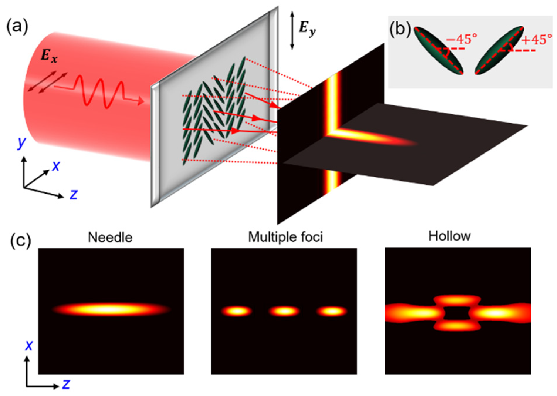
2.1. Design Principle of LC Gratings Based on PB Phase

Figure 1a illustrates the principle of adopting aperiodic LC gratings for diverse optical pattern generation. The core idea is to optimize the Pancharatnam–Berry (PB) phase configuration and then obtain the rigid director orientations of the LC molecules. According to the optical birefringence of LC materials, the LC devices should first satisfy the half-wave condition, which means the thickness of the LC layer should be properly chosen so as to make the accumulated dynamic phase retardation along the z-direction meet the half-wave condition. Under this condition, the transmission of LC devices can be represented by the Jones matrix J = ( cos 2 α sin 2 α sin 2 α cos 2 α ) , assuming that the in-plane azimuthal angle of the LC director is α. For simplicity, the LC directors in this study are assumed to orient at π/4 and −π/4 (Figure 1b), corresponding to phase retardations of π and 0, respectively. As a proof of concept, this study aims to optimize aperiodic LC gratings to realize multiple optical patterns, including needle beam, multiple foci, and hollow beam (Figure 1c). When the linearly x-polarized light impinges on the LC grating, the emitted electric field E is given as:
( E outx E outy ) = J ± 45 ° ( E inx E iny ) = ( cos ( ± 2 × 45 ° ) sin ( ± 2 × 45 ° ) sin ( ± 2 × 45 ° ) cos ( ± 2 × 45 ° ) ) ( 1 0 ) = ( 0 ± 1 )
where Einx(x, y, 0) and Einy(x, y, 0) denote the incident electric field components along the x and y directions, respectively. This implies that the transmitted light becomes linearly y-polarized, as E outx ( x , y , 0 ) = 0 and E outy ( x , y , 0 ) = ± 1 . We propose to simulate the propagation property of the diffracted light along the optical axis using the VRS method [41], where the electric field components of the diffracted light can be written as
E ± 45 ° x ( u , v , z ) = 0 E ± 45 ° y ( u , v , z ) = 1 2 π R 2 z exp ( i k n R ) R 2 ( i k n 1 R ) d x d y E ± 45 ° z ( u , v , z ) = 1 2 π R 2 ( y v ) × [ exp ( i k n R ) R 2 ( i k n 1 R ) ] d x d y
where R2 = z2 + (xu)2 + (y − v)2, k is the wave number, n is the refractive index of the medium space, and (u, v, z) represent the observation planes. The total field intensity of the diffraction pattern in the observation plane can then be calculated as follows: I = | E x | 2 + | E y | 2 + | E z | 2 , according to Equation (2).
Figure 1. The principle of adopting LC gratings for diverse optical pattern generation. (a) Schematic illustration showing the generation of multiple patterns when x-polarized light is impinging on the LC grating. (b) The director orientation of the LC molecules corresponding to phase retardation of π and 0. (c) Multiple optical patterns including optical needle, multiple foci, and hollow beam.

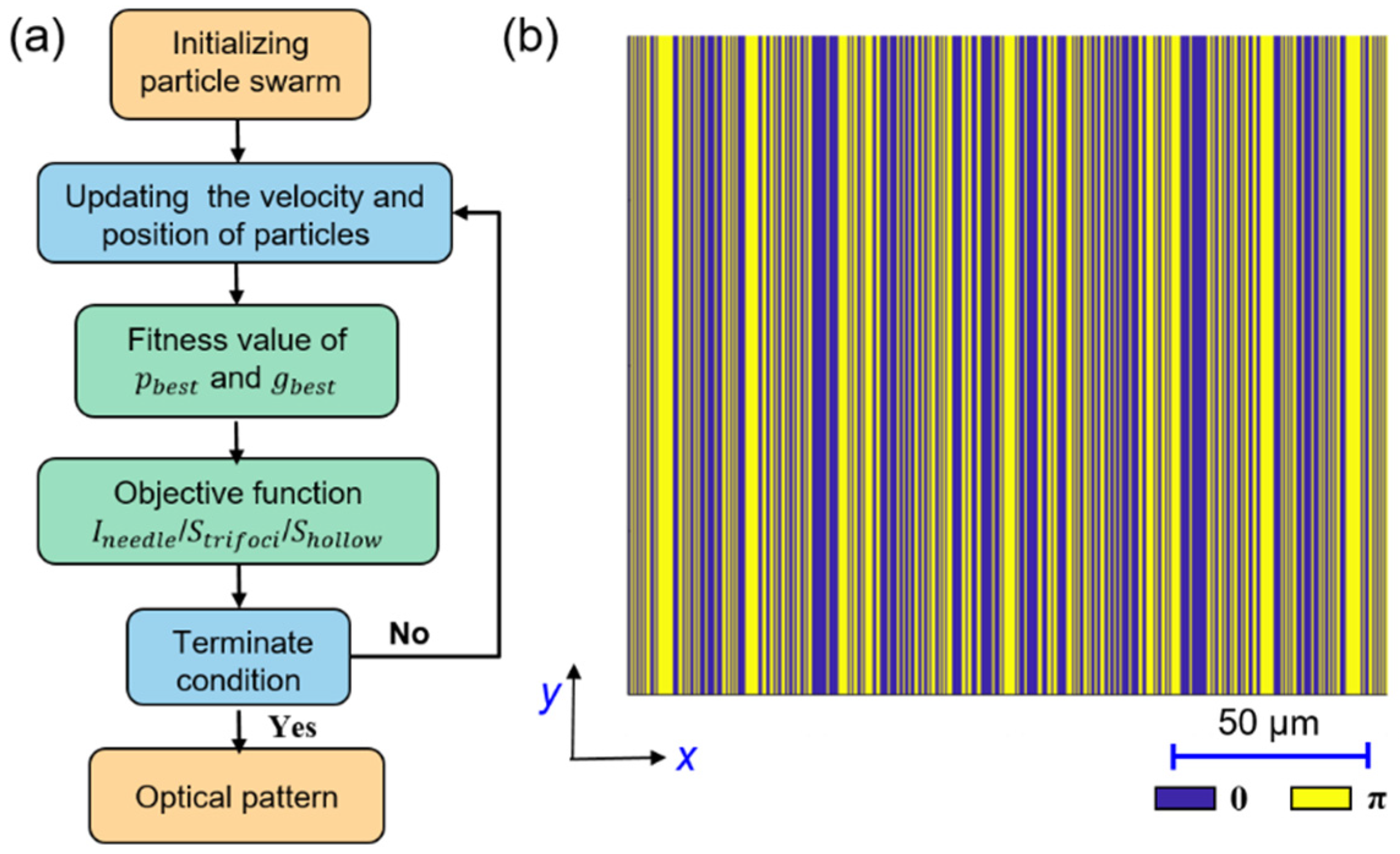
2.2. The Binary Particle Swarm Optimization Algorithm

The building blocks of the LC grating are 0.5 μm wide rectangular strips, each with either π/4 or −π/4 director orientation, corresponding to a PB phase retardation of π or 0, respectively. The aim of the customized design is to find the optimal phase profile for the objective LC grating, based on the unit building blocks. The BPSO algorithm, which is proven to be suitable for generating 0 or π phase change with fast convergence [36,42], is proposed to optimize the orientation configuration of the target light field. The flow chart of BPSO for LC grating design is depicted in Figure 2a. First, a large number of 0 and 1 arrays, corresponding to the phase distribution of 0 and π, are generated by the random function to initialize the population, where each phase distribution group represents a random LC grating. After that, the light intensity distribution generated by each group of phase profiles (namely the LC grating) is calculated using the VRS method. According to the optical performance of each random LC grating, the local optimum phase distribution is selected. A comparison between the local optimum and the global optimum is conducted to update the new global optimum. Meanwhile, the position and speed of 0 and π phase distribution are updated in the iteration. The iteration ends after the focal spot corresponding to the globally optimal phase distribution meets the target termination condition. Otherwise, the iteration goes back to step 2. Figure 2b shows an example of the LC grating consisting of rectangular blue and yellow regions, where the smallest width is 0.5 μm.
Figure 2. (a) The flow chart of BPSO for LC grating design. (b) Phase distribution of the LC grating.
In the process of optimization, the LC grating director orientation field is considered to update the BPSO algorithm’s velocity and position during the iterative process. It can be expressed as [36]:
v ( k , : ) = ω v ( k , : ) + c 1 r a n d [ p b e s t ( k , : ) x ( k , : ) ] + c 2 r a n d [ g b e s t ( k , : ) x ( k , : ) ]
where ω is a dynamic weight, c1 and c2 are the learning factors, rand is an isolated random function to generate director orientation arrangement, x(k,:) and v(k,:) are the particle position and velocity respectively, and pbest(k,:) and gbest(k,:) are the local best and global best light field fitness, respectively. After abstracting with the sigmoid ambiguity function vs(k,:) = 1/(1 + e−v(k,:)), we can map the velocity change from v(k,:) to vs(k,:) with a value between 0 and 1.
Similarly, we can establish a rectangle function to decide the particle position x(k,t) by changing the mapping to 0 or 1 using function x ( k , t ) = { 1 , v s ( k , t ) > r a n d 0 , v s ( k , t ) r a n d , which corresponds to the phase of 0 or π in the LC grating. Hence, different kinds of light fields can be realized and optimized by setting different objective functions and convergence conditions, such as needle beam, multi-foci, or hollow beam.

3. Results and Discussion

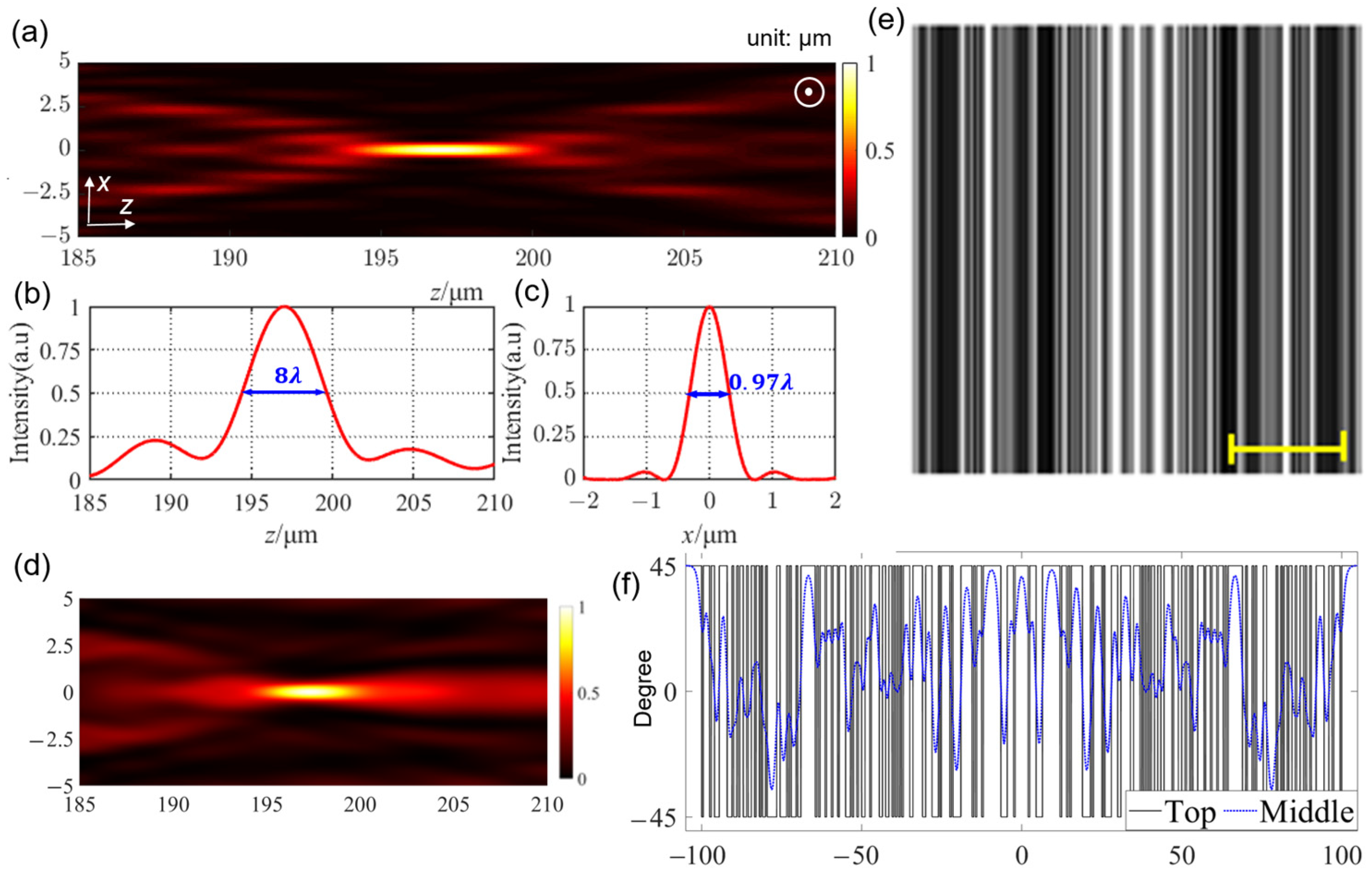
3.1. LC Grating for Needle Beam

We start by introducing how to design LC gratings for needle beam generation. We first construct a rectangle function as the objective function to define the needle beam, which is given as follows:
I n e e d l e ( z ) = { 1 , ( z 1 < f < z 2 ) 0 , ( e l s e )
where z1 and z2 are the front and rear endpoints of the target focus, respectively, and f is the focus position. We propose controlling the shape of the focal spot using a set of convergence conditions for the needle beam, as follows:
{ 185 μ m < f < 210 μ m 2 × | z h z f | 8 λ F W H M f < λ
where zh is the position with half-maximum intensity, zf is the center of the optical needle beam, and FHHMf is the full width at half maximum (FWHM) along the x-axis. Equations (4) and (5) helps to define a needle beam with subwavelength size along the x-axis and length larger than 8 λ.
For all the studies in this article, the working wavelength of incidence with linear x-polarization is assumed to be λ = 632.8 nm. The length of the LC grating along the y-axis is set to a = 200 μm, and the size of the unit pixel for building the grating is 0.5 μm. Based on the MATLAB platform, the BPSO algorithm, together with the objective function in Equation (4) and the terminate conditions in Equation (5), are coded to optimize the LC grating for forming a needle beam. Table 1 shows one of the optimal LC grating geometrical parameters for needle beam generation, which consists of 86 strips with designed phase distribution. Each group of positions denotes the two margins (inner and outer) of each strip with an identical phase (0 or π). Figure 3a depicts the simulated intensity distribution of the needle beam in the xz-plane based on the VRS method. The polarization of the optical pattern extending along the y-direction is linearly y-polarized. The FWHM of the needle along the optical axis is 8 λ (Figure 3b), and the FWHM along the x-axis is 0.97 λ (Figure 3c). These results reveal that the designed grating successfully realizes the objectives given by Equations (4) and (5).
Table 1. The Optimal LC Grating Geometrical Parameters for Needle Beam Generation *.
Figure 3. Optimized LC grating for needle beam generation. (a) Intensity distribution along the xz-plane. The white-circled dot represents that the polarization direction of the light is along the y-axis. (b) Intensity distribution along the optical axis. (c) Transverse intensity distribution along the focal plane. (d) The simulated light field distribution based on the simulated director distribution of E7. (e) The simulated POM image of the LC grating. Scale bar: 50 μm. (f) The LC director angles of the grating as a function of the x-axis.
However, it should be noted that the simulation results (Figure 3a–c) assume that the LC grating is composed strictly of strips with either zero or π phase modulation. This may be different from the realistic director distribution or PB phase of the LC grating, due to the director transition between neighboring strips with discrete PB phases, namely jumping director orientations. Hence, we also simulated the LC director distribution of the designed LC grating by minimizing the Q-tensor free energy [43]. We assumed that E7 (k11 = 11.1 pN, k22 = 7.4 pN, k33 = 17.1 pN, ne = 1.7396, and no = 1.522) was adopted to produce the designed LC grating. The calculated light field distribution of the LC grating (Figure 3d) shows a needle beam at the designed position, which matches well with the result shown in Figure 3a. We also calculated the polarized optical microscope (POM) image (Figure 3e) of the LC grating, based on the simulated spatial LC director distribution. These results indicate that the optimized LC grating is capable of generating a needle beam. In order to obtain the directors of LC molecules in the steady state, the phase retardations of all the strips were set to zero or π (directors orient at + or −45 degrees) according to the optimized phase profile of the LC grating at the beginning. However, in real cases, the director in the middle region of the LC layer along the z-axis does not exactly distribute according to the ideal orientations (+ or −45 degrees), due to the influence of the orientations of adjacent stripes. Therefore, there is twist deformation due to the difference in the azimuthal angle of the LC director in the z-direction, when the steady state of the LC director configuration is realized after the lowest Q-tensor free energy is reached. This phenomenon can be observed in Figure 3f, where the black curve plots the director angles of LC molecules at the top of the LC layer as a function along the x-axis, and the dashed blue curve denotes the director angles in the middle of the LC layer. Here, the phase retardation at the adjacent regions with different preset orientation angles is not strictly 0 or π in the steady state.

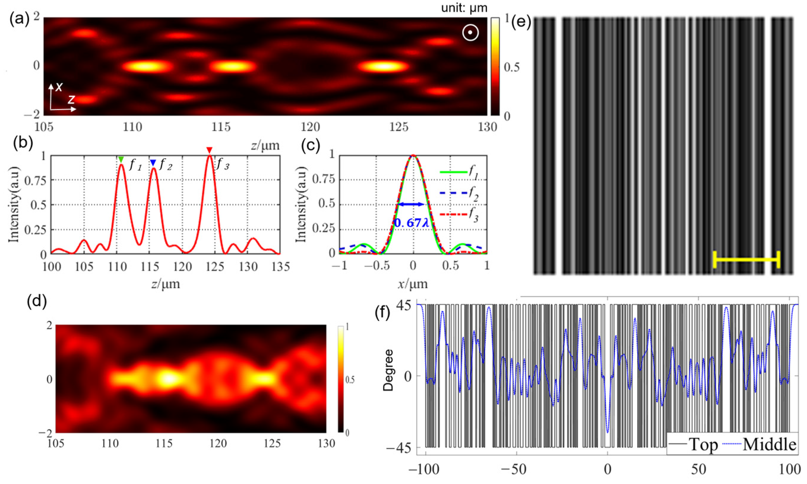
3.2. LC Grating for Linear Multi-Foci

In the design of multi-foci, we assume that these foci are located linearly along the optical axis. In order to achieve relatively pure and uniform focal spots without prominent sidelobes, the variance of the peak and valley of each focus is adopted to construct the objective function, which is expressed below:
S t r i f o c i = i = 1 3 1 3 ( I h - a v g I i ) 2 + j = 1 2 1 2 ( I l a v g I j ) 2
where Ih-avg and Il-avg are the average intensities of the peak and valley of the foci along the optical axis, respectively, and Ii and Ij are the average intensities of the foci. The convergence condition is set as follows:
{ 100 μ m < f i < 135 μ m   ( i = 1 , 2 , 3 ) F W H M i < λ   ( i = 1 , 2 , 3 ) I i 0.9 & I i 0.1
where fj is the position of each focus along the z-axis, and FWHMi is the FWHM of each focus along the x-axis.
Table 2 shows one of the optimal LC grating geometrical parameters for multi-foci generation, which consists of 109 strips with designed phase distribution. Figure 4a depicts the simulated intensity distribution of the multi-foci in the xz-plane, which is linearly y-polarized. The simulation results clearly show three foci at focal lengths of f1 = 110.7 μm, f2 = 115.7 μm, and f3 = 124.2 μm (Figure 4b). The FWHM of the multi-foci is 0.67 λ along the x-axis (Figure 4c). These results reveal that the designed grating successfully realizes the objective given by Equations (6) and (7). We also simulated the LC director distribution of the designed LC grating and calculated the light field distribution of the LC grating (Figure 4d). Our results match those shown in Figure 4a, except for the slight difference in the purity of the foci and the sidelobes. This may be caused by the director transition between adjacent strips with different PB phases. The POM image (Figure 4e) of the LC grating was also simulated based on the simulated spatial LC director distribution. These results indicate that the optimized LC grating is capable of generating multi-foci. We also plotted the director angles of the LC molecules at the top and in the middle of the LC layer as a function of the x-axis (Figure 4f), resulting in a trend similar to that in Figure 3f. It can be inferred that the intensity difference between Figure 4a,d arises from the director transition, which is depicted by Figure 4f.
Table 2. The Optimal LC Grating Geometrical Parameters for Linear Multi-foci Generation *.
Figure 4. Optimized LC grating for linear multi-foci generation. (a) Intensity distribution in the xz-plane. The white-circled dot represents that the polarization direction of the light is along the y-axis. (b) Intensity distribution along the optical axis. (c) Intensity distribution along the three focal planes (ffocus1 = 110.7 μm, ffocus2 = 115.7 μm, ffocus3 = 124.2 μm). (d) The simulated light field distribution based on the simulated director distribution of E7. (e) The simulated POM image of the LC grating. Scale bar: 50 μm. (f) The LC director angles of the grating as a function of the x-axis.

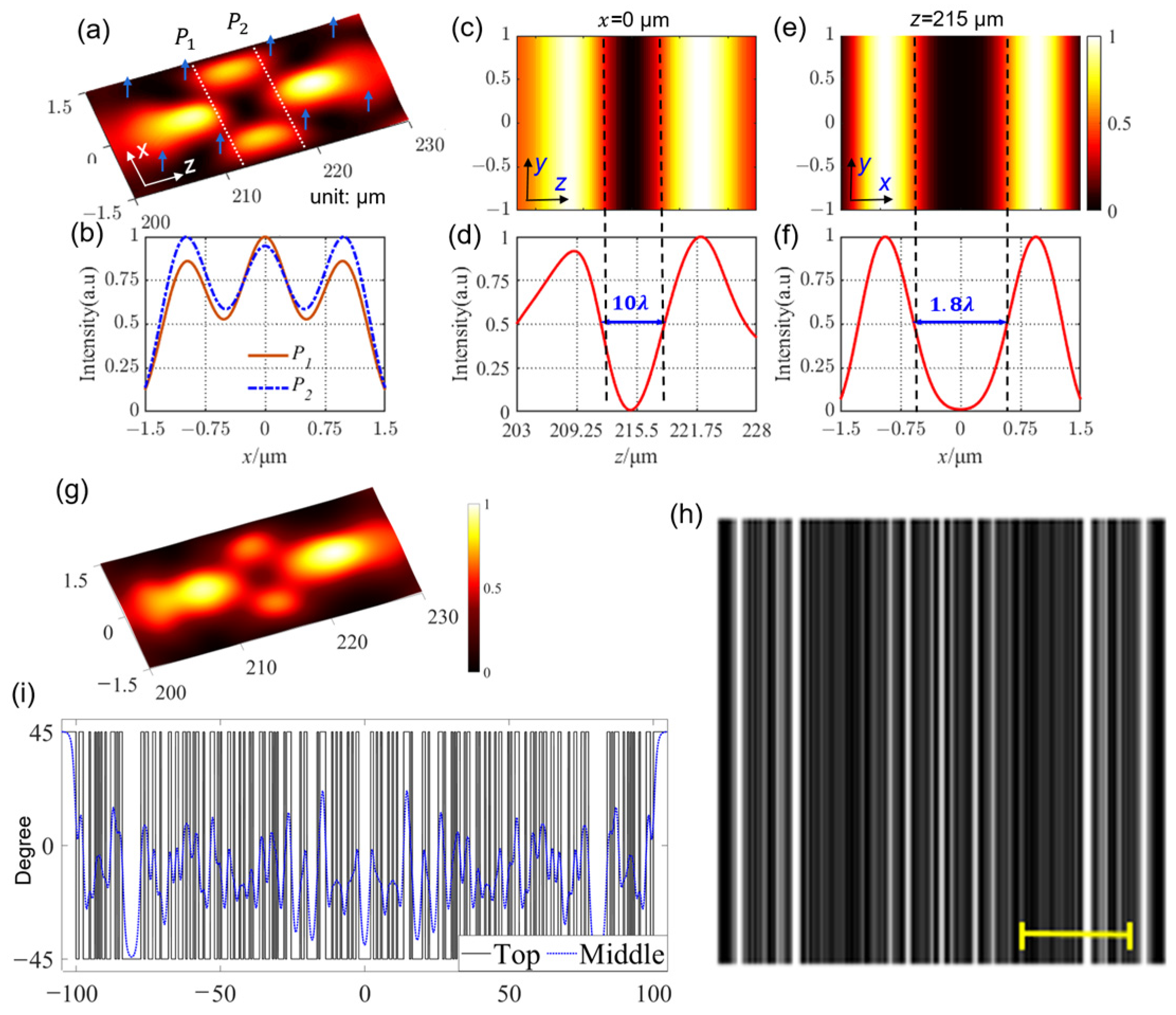
3.3. LC Grating for Hollow Beam

Hollow beam, also known as dark hollow beam, is a kind of beam with low or null intensity in the center, surrounded by a strong-intensity region [12,44]. Different from a conventional 2D hollow beam [44], the hollow beam based on an aperiodic LC grating is a 1D beam with a hollow channel, where a dark channel is formed in the direction perpendicular to the optical axis. Hence, the hollow channel beam should contain two adjacent peaks along the optical axis. The valley between these two peaks should also be the valley between the two lateral peaks along the x-axis. Similar to the design of multi-foci, the variance of the peaks along the z-axis and those along the x-axis are adopted to construct the objective function:
S hollow - pipe = i = 1 2 1 2 ( I z - a v g I i ) 2 + j = 1 2 1 2 ( I x a v g I j ) 2
where Iz-avg and Ix-avg are the average intensities of the two peaks along the z-axis and x-axis, respectively. We can set the convergence conditions for the hollow beam as follows:
200 μ m < f i < 230 μ m ( i = 1 , 2 ) I z min 10 2 I z a v g 0.9 & I x a v g 0.9 5 λ z 2 l e f t z 1 r i g h t 15 λ λ x 2 l e f t x 1 r i g h t 2 λ
where Izmin is the intensity of the hollow beam in the center; fj is between two focus positions on the z-axis; and z2left, z1right and x2left, x1right are the positions with half-maximum intensity on the z-axis and x-axis, respectively.
Table 3 shows one of the optimal LC grating geometrical parameters for hollow beam generation, which consists of 93 strips with designed phase distribution. Figure 5a depicts the simulated light field intensity distribution of the hollow beam in the xz-plane, which is linearly y-polarized. Figure 5b plots the light field intensity distributions along the white dashed lines (p1 and p2) in Figure 5a, which reveal that a null field is encircled by a high-intensity wall. The light field intensity distributions in the yz-plane at x = 0 (Figure 5c), along the z-axis at x = 0 (Figure 5d), in the xy-plane at z = 215 μm (Figure 5e), and along the x-axis at z = 215 μm (Figure 5f) are also plotted. These simulation results indicate that the designed grating successfully realizes the objective given by Equations (8) and (9). The size of the null field inside the hollow is estimated to be 10 λ by 1.8 λ. As in the studies of needle beam and multi-foci, we also simulated the LC director distribution of the designed LC grating and calculated the light field distribution of the LC grating (Figure 5g), which matches the result shown in Figure 5a. The POM image (Figure 5h) of the LC grating was also simulated based on the simulated spatial LC director distribution. In Figure 5i, we plotted the director angles of the LC molecules at the top and in the middle of the LC layer as a function along the x-axis, resulting in a similar trend to those seen in Figure 3f and Figure 4f. These results indicate that the optimized LC grating is capable of generating a hollow beam. A one-dimensional pipe or channel with low energy (zero energy) in the center is formed perpendicular to the propagation direction, which may inspire applications in dark-field massive-particle manipulation [45]. It should also be mentioned that this method can be extended to design LC gratings with other functionalities, similar to those of metagratings [4,5,35,39]. However, the LC gratings with designable functionalities have many advantages including an easy and cost-effective fabrication process, as it is no longer necessary to fabricate nanoscatters [1,34] relying on sophisticated and time-consuming lithography processes.
Table 3. The Optimal LC Grating Geometrical Parameters for Hollow Beam Generation *.
Figure 5. Optimized LC grating for hollow beam generation. (a) The simulated light field intensity distribution in the xz-plane. The blue arrows denote that the hollow beam is linearly y-polarized. (b) The light field intensity distributions along the white dashed lines p1 and p2 in Figure 5a. (c) Intensity distribution in the yz-plane at x = 0. (d) Intensity along the z-axis at x = 0. (e) Intensity distribution in the xy-plane at z = 215 μm. (f) Intensity along the x-axis at z = 215 μm. (g) The simulated light field distribution based on the simulated director distribution of E7. (h) The simulated POM image of the LC grating. Scale bar: 50 μm. (i) The LC director angles of the grating as a function of the x-axis.
In this study, the minimum orientation region of our device is assumed to be 0.5 μm, with an LC layer thickness of approximately 1.45 μm (to satisfy the half-wave condition). In principle, a transition status exists in the nematic LC molecules between two adjacent regions with different director orientations, as shown in Figure 3f, Figure 4f, and Figure 5i. The smaller the strips with similar orientation, the greater the transition effect. Theoretically, the line width could be smaller if the LC layer thickness is further reduced. However, it is rather challenging to reduce the LC thickness to less than 1 μm in the experiment, due to the availability of the nanospacers with high unity to create such a cell gap [25,26,27]. Hence, the line widths with a strictly identical phase cannot be made infinitely small. Indeed, there is a compromise between LC layer thickness and line width. The reported line width that can be reached using plasmonic metamasks is in the order of one working wavelength [27,28], which may enable the creation of various flat optics based on LC materials apart from the aperiodic gratings with designable functionalities in this study.

4. Conclusions

In summary, a versatile method based on BPSO for efficiently designing aperiodic LC gratings to produce customized optical patterns is proposed and theoretically demonstrated in this study. Three kinds of typical optical patterns, optical needle, multi-foci, and hollow beam, are successfully designed using LC gratings. We simulated the optical performance of these LC gratings using both the VRS method (with discrete zero or π phase, in this article) and the actual director orientations. We found that these results matched each other well, thus proving the effectiveness of the optimization method based on discrete zero or π phase. This study paves the way for designing LC gratings with engineered functionalities, which may find applications in optical tweezers, laser delivery systems, and laser scanning imaging.

Author Contributions

Conceptualization, H.Y. and G.Z.; methodology, J.W., B.T. and D.Y.; data curation, C.L. and Z.G.,; writing—review and editing, H.Y., C.L. and Z.G.; All authors have read and agreed to the published version of the manuscript.

Funding

This work was partially supported by the National Key R&D Program of China (2021YFB3600602), the Science and Technology Program of Guangzhou (202102020604), the Special Program on Key Fields for Colleges and Universities of Guangdong Province (2021ZDZX1048), the Natural Science Foundation of Guangdong Province (2021A1515010623), the Guangdong Provincial Key Laboratory of Optical Information Materials and Technology (2017B030301007), and the 111 project.

Institutional Review Board Statement

Not applicable.

Data Availability Statement

Data underlying the results presented in this paper are not publicly available at this time, but may be obtained from the authors on reasonable request.

Conflicts of Interest

The authors declare no conflict of interest.

References

  1. Yuan, G.; Zhelude, N.I. Detecting nanometric displacements with optical ruler metrology. Science 2019, 364, 771–775. [Google Scholar] [CrossRef]
  2. Yang, Z.; Albrow-Owen, T.; Cai, W.; Hasan, T. Miniaturization of optical spectrometers. Science 2021, 371, 480. [Google Scholar] [CrossRef]
  3. Field, J.W.; Berry, S.A.; Bannerman, R.H.S.; Smith, D.H.; Gawith, C.B.E.; Smith, P.G.R.; Gates, J.C. Highly-chirped bragg gratings for integrated silica spectrometers. Opt. Express 2020, 28, 21247. [Google Scholar] [CrossRef]
  4. Hua, J.; Hua, E.; Zhou, F.; Shi, J.; Wang, C.; Duan, H.; Hu, Y.; Qiao, W.; Chen, L. Foveated glasses-free 3D display with ultrawide field of view via a large-scale 2D-metagrating complex. Light Sci. Appl. 2021, 10, 213. [Google Scholar] [CrossRef]
  5. Wan, W.; Qiao, W.; Pu, D.; Li, R.; Wang, C.; Hu, Y.; Duan, H.; Guo, L.; Chen, L. Holographic sampling display based on metagratings. iScience 2020, 23, 100773. [Google Scholar] [CrossRef]
  6. Doneus, M.; Doneus, N.; Briese, C.; Pregesbauer, M.; Mandlburger, G.; Verhoeven, G. Airborne laser bathymetry—Detecting and recording submerged archaeological sites from the air. J. Archaeol. Sci. 2013, 40, 2136–2151. [Google Scholar] [CrossRef]
  7. Mizuno, K.; Ono, S.; Shimoe, O. Interaction between coherent light waves and free electrons with a reflection grating. Nature 1975, 253, 184–185. [Google Scholar] [CrossRef]
  8. Wang, Y.; Wang, X.; Flueckiger, J.; Yun, H.; Shi, W.; Bojko, R.; Jaeger, N.A.; Chrostowski, L. Focusing sub-wavelength grating couplers with low back reflections for rapid prototyping of silicon photonic circuits. Opt. Express 2014, 22, 20652–20662. [Google Scholar] [CrossRef]
  9. Chen, G.; Zhang, K.; Yu, A.; Wang, X.; Zhang, Z.; Li, Y.; Wen, Z.; Li, C.; Dai, L.; Jiang, S.; et al. Far-field sub-diffraction focusing lens based on binary amplitude-phase mask for linearly polarized light. Opt. Express 2016, 24, 11002–11008. [Google Scholar] [CrossRef]
  10. Rochon, P.; Batalla, E.; Natansohn, A. Optically induced surface gratings on azoaromatic polymer films. Appl. Phys. Lett. 1995, 66, 136–138. [Google Scholar] [CrossRef]
  11. Kumar, J.; Li, L.; Jiang, X.L.; Kim, D.; Lee, T.S.; Tripathy, S. Gradient force: The mechanism for surface relief grating formation in azo benzene functionalized polymers. Appl. Phys. Lett. 1998, 77, 2096–2098. [Google Scholar] [CrossRef]
  12. Heitmann, D.; Pole, R.V. Two-dimensional focusing holographic grating coupler. Appl. Phys. Lett. 1980, 37, 585–587. [Google Scholar] [CrossRef]
  13. Piazzolla, S.; Jenkins, B.K. Holographic grating formation in photopolymers. Opt. Lett. 1996, 21, 1075–1077. [Google Scholar] [CrossRef]
  14. Zhou, Q.; Zhang, J.; Ren, X.; Xu, Z.; Liu, X. Multi-bottle beam generation using acoustic holographic lens. Appl. Phys. Lett. 2020, 116, 133502. [Google Scholar] [CrossRef]
  15. Oscurato, S.L.; Reda, F.; Salvatore, M.; Borbone, F.; Maddalena, P.; Ambrosio, A. Large-scale multiplexed azopolymer gratings with engineered diffraction behavior. Adv. Mater. Interfaces 2021, 8, 2101375. [Google Scholar] [CrossRef]
  16. Carroll, T.O. Liquid-crystal diffraction grating. Appl. Phys. Lett. 1972, 43, 767–770. [Google Scholar] [CrossRef]
  17. Bryan-Brown, G.P.; Brown, C.V.; Sage, I.C.; Hui, V.C. Voltage-dependent anchoring of a nematic LC on a grating surface. Nature 1998, 392, 365–367. [Google Scholar] [CrossRef]
  18. Chen, H.; Tan, G.; Huang, Y.; Weng, Y.; Choi, T.H.; Yoon, T.H.; Wu, S.T. A low voltage LC phase grating with switchable diffraction angles. Sci. Rep. 2017, 7, 39923. [Google Scholar] [CrossRef]
  19. Katayama, K.; Kato, D.; Nagasaka, K.I.; Miyagawa, M.; Sohn, W.Y.; Lee, K.W. Origin of optical nonlinearity of photo-responsive liquid crystals revealed by transient grating imaging. Sci. Rep. 2019, 9, 5754. [Google Scholar] [CrossRef]
  20. Shin, Y.; Jiang, Y.; Wang, Q.; Zhou, Z.; Qin, G.; Yang, D.K. Flexoelectric-effect-based light waveguide liquid crystal display for transparent display. Photon. Res. 2022, 10, 407–414. [Google Scholar] [CrossRef]
  21. Sung, G.F.; Wu, P.C.; Zyryanov, V.Y.; Lee, W. Electrically active and thermally passive liquid-crystal device toward smart glass. Photon. Res. 2021, 9, 2288–2295. [Google Scholar] [CrossRef]
  22. Lu, X.; Li, X.; Guo, Y.; Pu, M.; Wang, J.; Zhang, Y.; Li, X.; Ma, X.; Luo, X. Broadband high-efficiency polymerized liquid crystal metasurfaces with spin-multiplexed functionalities in the visible. Photon. Res. 2022, 10, 1380–1393. [Google Scholar] [CrossRef]
  23. Chiang, W.; Silalahi, H.; Chiang, Y.C.; Hsu, M.C.; Zhang, Y.S.; Liu, J.H.; Yu, Y.; Lee, C.R.; Huang, C.Y. Continuously tunable intensity modulators with large switching contrasts using liquid crystal elastomer films that are deposited with terahertz metamaterials. Opt. Express 2020, 28, 27676–27687. [Google Scholar] [CrossRef] [PubMed]
  24. Chiang, W.F.; Lu, Y.Y.; Chen, Y.P.; Lin, X.Y.; Lim, T.S.; Liu, J.H.; Lee, C.R.; Huang, C.Y. Passively tunable terahertz filters using liquid crystal cells coated with metamaterials. Coatings 2021, 11, 381. [Google Scholar] [CrossRef]
  25. Culbreath, C.; Glazar, N.; Yokoyama, H. Note: Automated maskless micro-multidomain photoalignment. Rev. Sci. Instrum. 2011, 82, 126107. [Google Scholar] [CrossRef]
  26. Wei, B.; Hu, W.; Ming, Y.; Xu, F.; Rubin, S.; Wang, J.; Chigrinov, V.; Lu, Y. Generating switchable and reconfigurable optical vortices via photopatterning of liquid crystals. Adv. Mater. 2014, 26, 1590–1595. [Google Scholar] [CrossRef] [PubMed]
  27. Guo, Y.; Jiang, M.; Peng, C.; Sun, K.; Yaroshchuk, O.; Lavrentovich, O.; Wei, Q. High-resolution and high-throughput plasmonic photopatterning of complex molecular orientations in liquid crystals. Adv. Mater. 2016, 28, 2353–2358. [Google Scholar] [CrossRef]
  28. Jiang, M.; Yu, H.; Feng, X.; Guo, Y.; Chaganava, I.; Turiv, T.; Lavrentovich, O.D.; Wei, Q. Liquid crystal Pancharatnam—Berry micro-optical elements for laser beam shaping. Adv. Opt. Mater. 2018, 6, 1800961. [Google Scholar] [CrossRef]
  29. Chen, K.; Hou, Y.; Chen, S.; Yuan, D.; Ye, H.; Zhou, G. Design, fabrication, and applications of liquid crystal microlenses. Adv. Opt. Mater. 2021, 9, 2100370. [Google Scholar] [CrossRef]
  30. Kobashi, J.; Yoshida, H.; Ozaki, M. Planar optics with patterned chiral liquid crystals. Nat. Photon. 2016, 10, 389. [Google Scholar] [CrossRef]
  31. Murray, B.S.; Pelcovits, R.A.; Rosenblatt, C. Creating arbitrary arrays of two-dimensional topological defects. Phys. Rev. E 2014, 90, 52501. [Google Scholar] [CrossRef]
  32. Wu, H.; Hu, W.; Hu, H.; Lin, X.; Zhu, G.; Choi, J.; Chigrinov, V.; Lu, Y. Arbitrary photo-patterning in liquid crystal alignments using DMD based lithography system. Opt. Express 2012, 20, 3038. [Google Scholar] [CrossRef]
  33. McConney, M.E.; Martinez, A.; Tondiglia, V.P.; Lee, K.M.; Langley, D.; Smalyukh, I.I.; White, T.J. Topography from topology: Photoinduced surface features generated in liquid crystal polymer networks. Adv. Mater. 2013, 25, 5880. [Google Scholar] [CrossRef] [PubMed]
  34. Ye, H.; Sun, Q.; Guo, Z.; Hou, Y.; Wen, F.; Yuan, D.; Qin, F.; Zhou, G. Theoretical realization of single-mode fiber integrated metalens for beam collimating. Opt. Express 2021, 29, 27521. [Google Scholar] [CrossRef] [PubMed]
  35. Xie, Y.; Quan, J.; Shi, Q.; Cao, Y.; Sun, B.; Xu, Y. Multi-functional high-efficiency light beam splitter based on metagrating. Opt. Express 2022, 30, 4125. [Google Scholar] [CrossRef] [PubMed]
  36. Khanesar, M.A.; Teshnehlab, M.; Shoorehdeli, M.A. A Novel Binary Particle Swarm Optimization. In Proceedings of the 2007 Mediterranean Conference on Control & Automation, Athens, Greece, 27–29 June 2007. [Google Scholar]
  37. Su, M.; Yang, B.; Liu, J.; Ye, H.; Zhou, X.; Xiao, J.; Li, Y.; Chen, S.; Fan, D. Broadband graphene-on-silicon modulator with orthogonal hybrid plasmonic waveguides. Nanophotonics 2020, 9, 1529. [Google Scholar] [CrossRef]
  38. Ma, W.; Liu, Z.; Kudyshev, Z.A.; Boltasseva, A.; Cai, W.; Liu, Y. Deep learning for the design of photonic structures. Nat. Photon. 2021, 15, 77. [Google Scholar] [CrossRef]
  39. Younes, R.; Dimitrios, L.S.; Andrea, A. Metagratings: Beyond the limits of Graded Metasurfaces for Wave Front Control. Phys. Rev. Lett. 2017, 119, 067404. [Google Scholar]
  40. Wang, H.; Hao, C.; Lin, H.; Wang, Y.; Lan, T.; Qiu, C.; Jia, B. Generation of super-resolved optical needle and multifocal array using graphene oxide metalenses. Opto-Electron. Adv. 2021, 2, 4. [Google Scholar] [CrossRef]
  41. Ye, H.; Qiu, C.-W.; Huang, K.; Teng, J.; Luk’yanchuk, B.; Yeo, S.P. Creation of longitudinally polarized subwavelength hotspot with ultra-thin planar lens: Vectorial Rayleigh Sommerfeld method. Laser Phys. Lett. 2013, 10, 065004. [Google Scholar] [CrossRef]
  42. Rogers, E.T.F.; Lindberg, J.; Roy, T.; Savo, S.; Chad, J.E.; Dennis, M.R.; Zheludev, N.I. A super-oscillatory lens optical microscope for subwavelength imaging. Nat. Mater. 2012, 11, 432–435. [Google Scholar] [CrossRef]
  43. Xiong, J.; Chen, R.; Wu, S.T. Device simulation of liquid crystal polarization gratings. Opt. Express 2019, 27, 18102. [Google Scholar] [CrossRef]
  44. Ye, H.; Huang, K.; Liu, H.; Wen, F.; Jin, Z.; Teng, J.; Qiu, C. Intrinsically shaping the focal behavior with multi-ring Bessel-Gaussian beam. Appl. Phys. Lett. 2017, 111, 031103. [Google Scholar] [CrossRef]
  45. Shvedov, V.G.; Rode, A.V.; Izdebskaya, Y.V.; Desyatnikov, A.S.; Krolikowski, W.; Kivshar, Y.S. Giant optical manipulation. Phys. Rev. Lett. 2010, 105, 118103. [Google Scholar] [CrossRef]
Disclaimer/Publisher’s Note: The statements, opinions and data contained in all publications are solely those of the individual author(s) and contributor(s) and not of MDPI and/or the editor(s). MDPI and/or the editor(s) disclaim responsibility for any injury to people or property resulting from any ideas, methods, instructions or products referred to in the content.

Article Metrics

Citations

Article Access Statistics

Multiple requests from the same IP address are counted as one view.