Article

Scanning Tunneling Microscopy of Intermediate Transformation Structures in Electric Arc Surfacing Modified with Titanium Carbonitrides on Pipe Steel

Laboratory of Physical Mesomechanics of Materials and Non-Destructive Testing, Institute of Strength Physics and Materials Science SB RAS, 634055 Tomsk, Russia
*
Author to whom correspondence should be addressed.
Crystals 2023, 13(1), 146; https://doi.org/10.3390/cryst13010146
Submission received: 6 December 2022 / Revised: 9 January 2023 / Accepted: 11 January 2023 / Published: 14 January 2023
(This article belongs to the Special Issue Advances in Surface Modification of Metals and Alloys)

Abstract

:
In the present paper, the structure of electric arc coatings modified with nanodispersed titanium carbonitride additives on low-carbon pipe steel is studied using optical, scanning tunneling, and transmission electron microscopy. The obtained “substrate-modified surface” compositions are tested for fracture toughness, and the derived test results are compared with the data for the compositions formed using commercial electrodes. It is found that the introduction of titanium carbonitride nanoparticles with the estimated content from 0.15 to 1 wt% refines the ferrite–pearlite structure. Scanning tunneling microscopy reveals acicular and lamellar structures in local regions of ferrite grains, which, by morphological features, are identified as lower bainite and acicular ferrite. It is concluded that the increase in fracture toughness of the “substrate-modified surface” composition is of a complex nature. First of all, this increase is associated with grain refinement, while the formation of intermediate transformation structures plays a secondary role.

1. Introduction

Surface modification of metals and alloys, despite its long history, remains one of the most effective methods of improving the functional properties of metals and alloys with no change in their chemical composition and bulk properties [1,2]. Surface modification is capable of increasing the reliability and life of the new and restored machine components and allows for the abandonment of expensive high-quality structural materials in favor of conventional structural materials, which makes this method cost efficient. Metals, alloys, and other materials with a modified surface demonstrate high wear resistance, hardness, corrosion resistance, fracture toughness, fatigue life, biocompatibility, and other properties [1,2,3].
A surface can be modified by various methods: chemical vapor deposition [4], physical vapor deposition [5], ion implantation [6], surface treatment with high-current electron beams [7], laser treatment [8], active gas metal arc welding [9], and electron beam and electric arc surfacing [2,3]. One of the most effective methods of surface modification is electric arc surfacing, which is often used for parts operating in conditions of abrasive wear and impact loads [10].
Such properties of the “substrate-modified surface” system as wear resistance, plasticity, cold resistance, and crack resistance can be improved by adding nanodispersed refractory particles [11,12,13,14]. The introduction of refractory nanoparticles into the melt pool enables a control over metal crystallization and austenite decomposition kinetics, thus resulting in the formation of favorable highly dispersed structures with regions of lower bainite and acicular ferrite [12,13].
Lower bainite and acicular ferrite are the most preferred structures of intermediate transformation, which increase almost all operational properties of the surface-modified material, in particular, fracture toughness [15]. The increase in properties is associated with such structural parameters of lower bainite and acicular ferrite as the size of bainite laths, dislocation density, and the size of carbides [15].
However, bainite formed during continuous cooling, in contrast to upper or lower bainite obtained by the isothermal process in low-carbon steels, exhibits a variety of fine morphological features [16,17,18,19,20], which are, however, difficult to distinguish through an optical microscope. Transmission electron microscopy (TEM), which is one of the most informative methods of crystallographic analysis of microscopic regions in metals and alloys, is sometimes also incapable of identifying lower bainite [21]. The kinetics of cementite precipitation in such steel is retarded during continuous cooling, which leads to significant confusion in characterizing several bainitic phases. [17]. Moreover, an intricate procedure of preparation of TEM foils makes this observational method inapplicable to statistically representative characterization of complex austenite decomposition products at a varying content of modifying additives.
Methods of scanning probe microscopy (SPM), namely, atomic force (AFM) and scanning tunneling microscopy (STM), have high horizontal and vertical resolution and are successfully used to study the mechanisms of austenite decomposition and fine morphological features of the resulting structures, such as grain-boundary ferrite [22], Widmanstatten ferrite [23], bainite [24,25,26,27,28,29], and martensite [30]. The relief was studied both on pre-polished samples to reveal austenite decomposition phases [24,27,30] and on samples that were chemically etched to see a structure [23,25,28,31].
An important advantage of SPM methods over TEM is the ease of preparation of microscopic samples, which allows for rapid representative sampling in the morphological study of the fine microstructure of a material. Several dozen of high-resolution 3D STM or AFM images can be easily obtained for several days. However, the observation of the morphology of austenite decomposition products in low-carbon steel is insufficient to detect carbide precipitates, which are often important for structure identification. Therefore, the most effective way to study surface layers modified by various additives is to combine the advantages of SPM and TEM.
The aim of the present paper is to perform an STM study of the microstructure of electric arc coatings with nanodispersed titanium carbonitride additives on low-carbon pipe steel and to analyze the fracture toughness of the ”substrate-modified surface” composition. Thin-foil transmission electron microscopy is performed for 0.15 TiCN-containing coatings that demonstrate the highest fracture toughness.

2. Materials and Methods

The subject of investigation is low-carbon low-alloy steel A516-55 (AISI, ASTM, ASME) (09G2S in Russian designation) taken as a substrate. Its chemical composition is given in Table 1.
Coatings were deposited by a manual electric arc method with MP-3 electrodes containing the modifying additive of nanodispersed titanium carbonitrides TiCxNy. Direct current of reverse polarity (I = 200–220 A) was used. Our preliminary studies showed higher mechanical properties in the composition of the “substrate-modified surface” obtained using electrodes within the content range of 0.15–0.25 wt% TiCN compared with ones prepared using commercial electrodes MP-3. An increase in the additive of nanopowders of the Fe-TiC0.5N0.5 composite material to more than 0.5 wt% leads to coalescence of nanoparticles with the formation of colonies of large (up to 1–3 μm) irregularly shaped precipitates in melt. The precipitates, being stress concentrators, reduce the crack resistance of the metal, which leads to a deterioration in mechanical properties. Therefore, the content range of 0.15–0.25 wt% TiCN was chosen to study the fine microstructure by STM and the composition containing 1 wt% TiCN was chosen as the upper limit for comparison.
The estimated content of titanium carbonitrides in the electrode coating was 0.15 wt%, 0.2 wt%, 0.25 wt%, and 1 wt%. The TiCxNy particle size ranged from 80 to 120 nm. According to the X-ray analysis data, the Fe-TiCN composite powder produced by self-propagating high-temperature synthesis contained the phases Ti2CN (71 wt%), TiC0.5N0.5 (9.25 wt%), Fe3C (5.72 wt%), and α-Fe (13.46 wt%). For comparison, we used reference specimens with coatings deposited with commercial MP-3 electrodes, whose chemical composition is given in Table 2.
The resulting surface-modified specimens with various estimated content of titanium carbonitride nanoparticles in the coating were used to prepare standard V-notch test samples measuring 55 × 10 × 10 mm3. Impact bending tests were carried out on an Instron MPX 450 pendulum impact tester in accordance with GOST 9454-78 (similar to U.S. standard ASTM E23-18).
For structural studies, samples measuring 10 × 10 × 1 mm3 were spark cut out of the coatings parallel to the surfacing plane. The samples were mechanically ground and polished with subsequent electrolytic polishing. For the morphological investigation of various phases in the coating, thin sections were etched in the 4% alcohol solution of nitric acid for 5 s. Metallographic studies were carried out with a Zeiss Axiovert 25 optical microscope. To obtain quantitative information about the effect of titanium carbonitride nanoparticles on the grain size, the secant method was used by means of the Gwiddion software [32]. The sizes of ferrite and pearlite grains were measured in a series of 7–10 typical optical images for each composition. The Gwiddion software allows us to receive data in a format compatible with the Origin app. Therefore, after obtaining the grain size data array, further statistical processing and description of the results for the model were carried out in the Origin app. The fine microstructure of the coatings was examined under an SMMT-2000 scanning tunneling microscope (Zelenograd) in the constant current mode (I = 2nA) at the voltage between the tip and the sample U = 100 mV.
Samples for TEM were prepared from the coating containing 0.15 wt% TiCN. A sample was mechanically polished to a thickness of 0.1 mm, and several discs 3 mm in diameter were punched out of the thinned sample. These discs were further ground to remove surface oxide and then perforated by single-jet electropolishing in the electrolyte of 133 mL acetic acid, 7 mL water, and 25 g chromic anhydride. The foils were examined under a JEM-100 CXII transmission electron microscope at a voltage of 100 keV in the imaging and microdiffraction modes.

3. Results

3.1. Fracture Toughness

Impact bending tests on V-notch specimens showed a strong influence of carbonitride nanoparticles in the coating on the fracture toughness of the surface-modified specimen. The values of room-temperature fracture energy and fracture toughness found from the analysis of changes in the force applied to the pendulum during the specimen fracture propagation are given in Table 3.
As can be seen from Table 3, the introduction of nanoparticles into the coating leads to a more than twofold increase in fracture toughness compared with the coating deposited with the commercial MP-3 electrode (42 J/cm2).

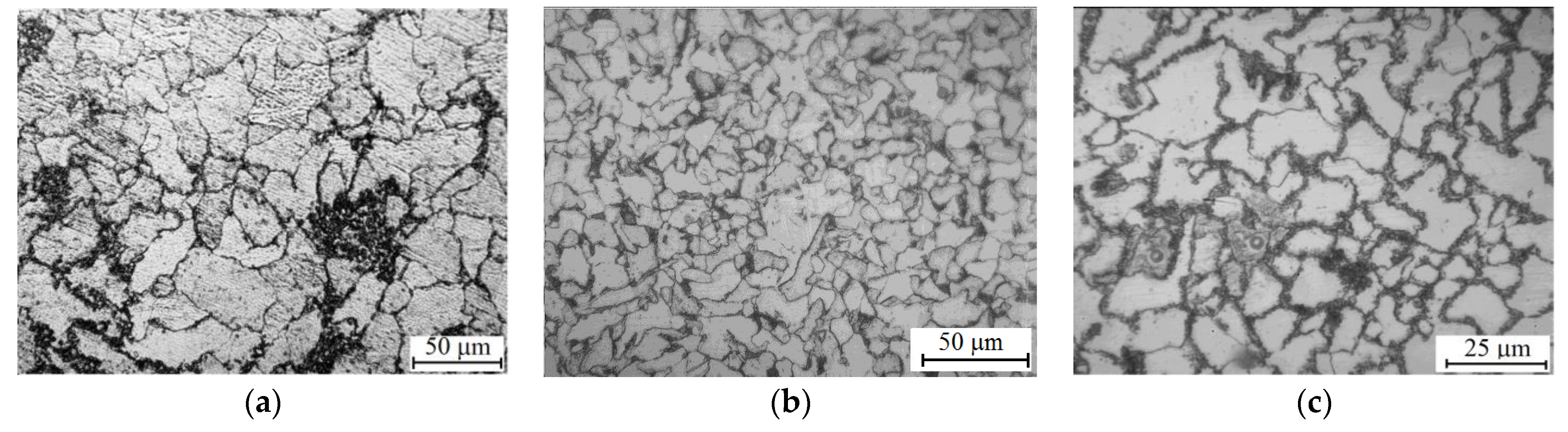
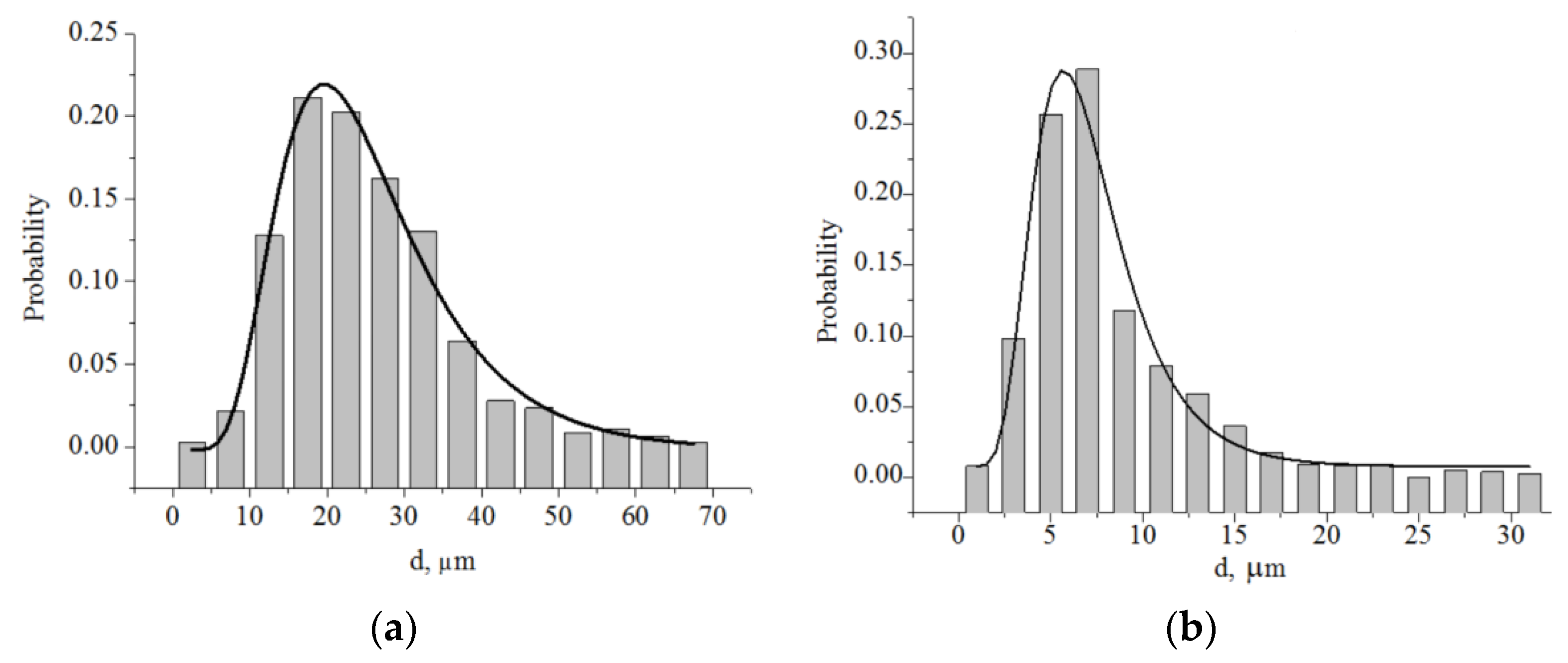
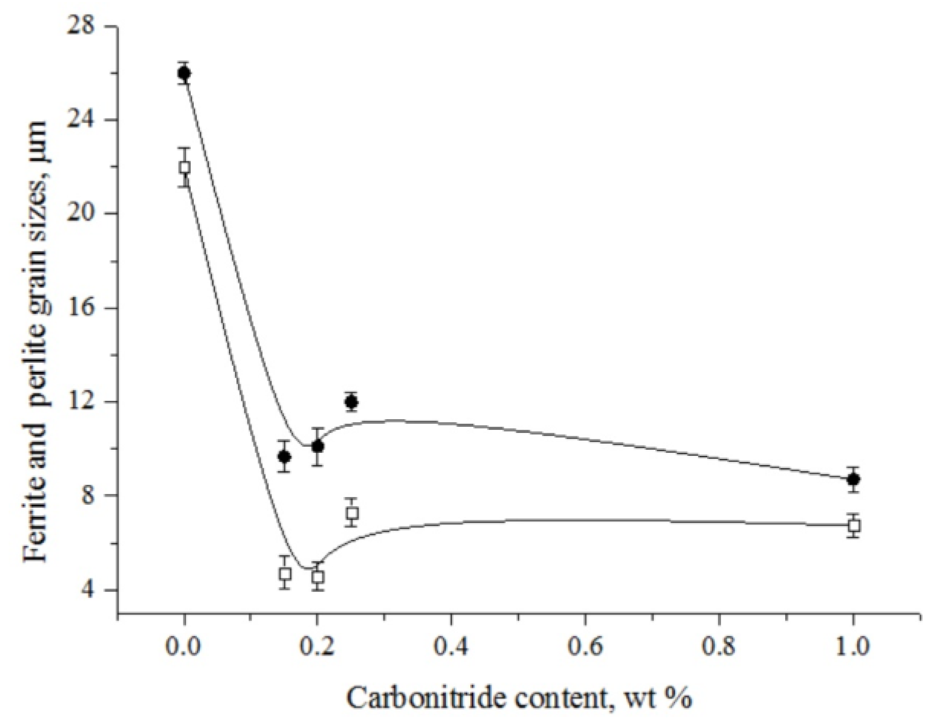
3.2. Optical Microscopy

Optical microscopy reveals a ferrite–pearlite structure in all electric arc coatings, with different dispersed structural components. Figure 1 exemplifies structures formed during surfacing with the commercial electrode and with electrodes modified by 0.25wt% and 1 wt% titanium carbonitride nanoparticles. As can be seen, the structure modified by titanium carbonitrides is more refined than that obtained with the commercial electrode.
Figure 2 shows grain size distribution histograms in coatings deposited with the commercial electrode (for ferrite grains) and electrodes containing 0.25 wt% titanium carbonitride nanoparticles (for pearlite grains). The analysis of the obtained results indicates that all histograms can be described by lognormal distribution functions (shown by solid lines in Figure 2a,b), whose parameters (median size and variance) depend on the content of nanoparticles in the coating. The average size of ferrite and pearlite grains in coatings with different estimated content of titanium carbonitride nanoparticles was calculated using the known relation <X> = Xcexp(w2/2), where <X> is the average size, Xc is the median size, and w is the lognormal distribution variance.
Figure 3 plots dependences of the ferrite and pearlite grain size on the content of titanium carbonitride nanoparticles in coatings. The size of ferrite and pearlite grains in coatings deposited with the commercial electrode without titanium carbonitride nanoparticles is exhibited at the beginning of the dependence.
As can be seen from Figure 3, the average size of ferrite and pearlite grains in the coatings modified by titanium carbonitride nanoparticles is 2–3 times smaller than that in the coatings deposited with the commercial electrode. This confirms the qualitative conclusion about the structure refinement in coatings modified by titanium carbonitrides, which was made based on the analysis of optical images (Figure 1). Structure refinement improves the coating strength due to grain boundary strengthening and contributes to an increase in fracture toughness due to retardation of cracks at grain boundaries.

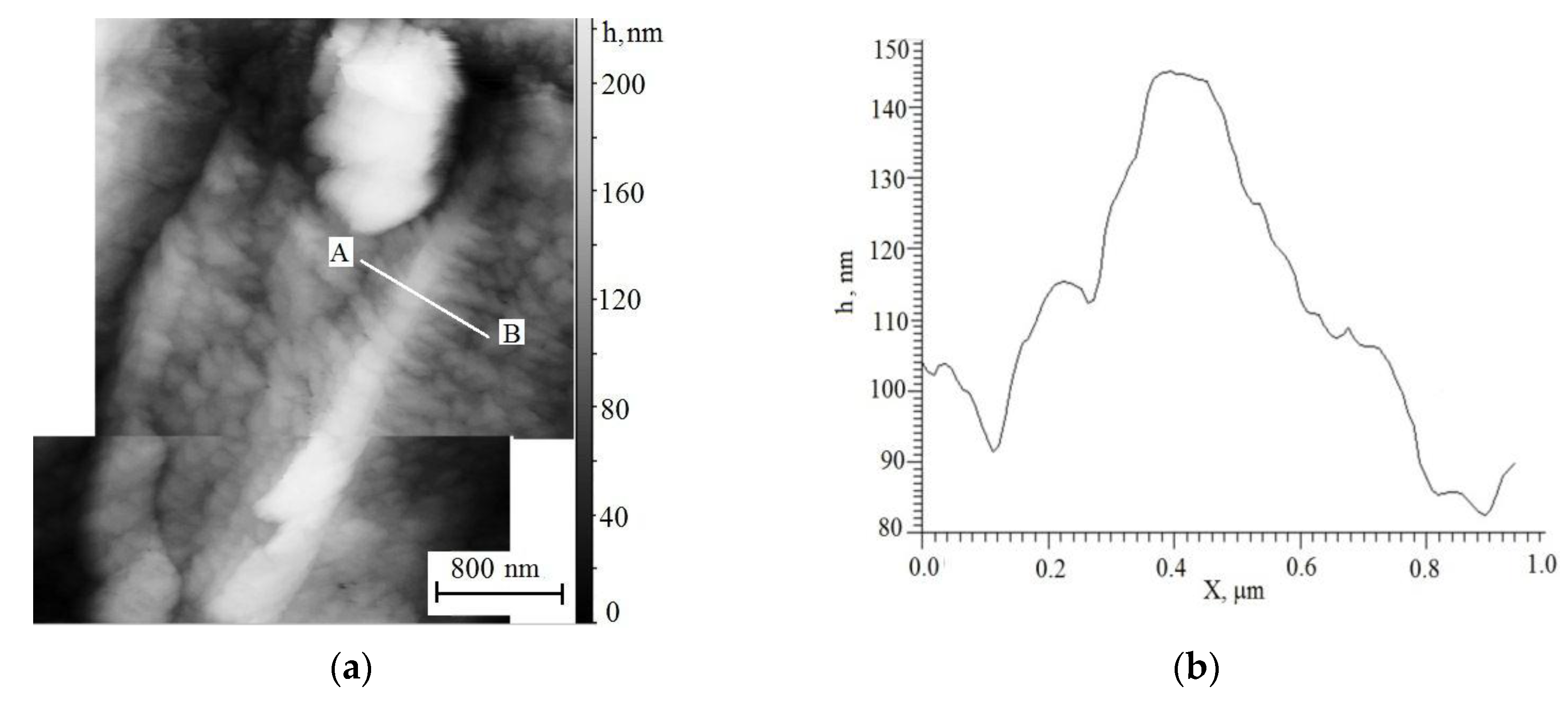
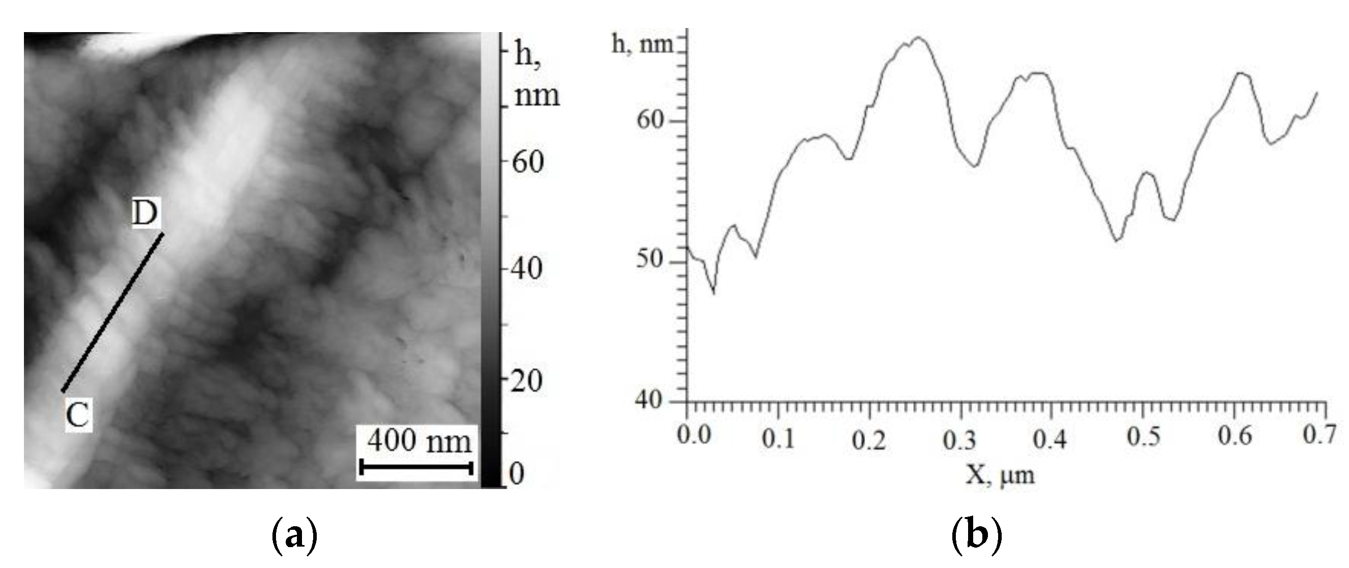
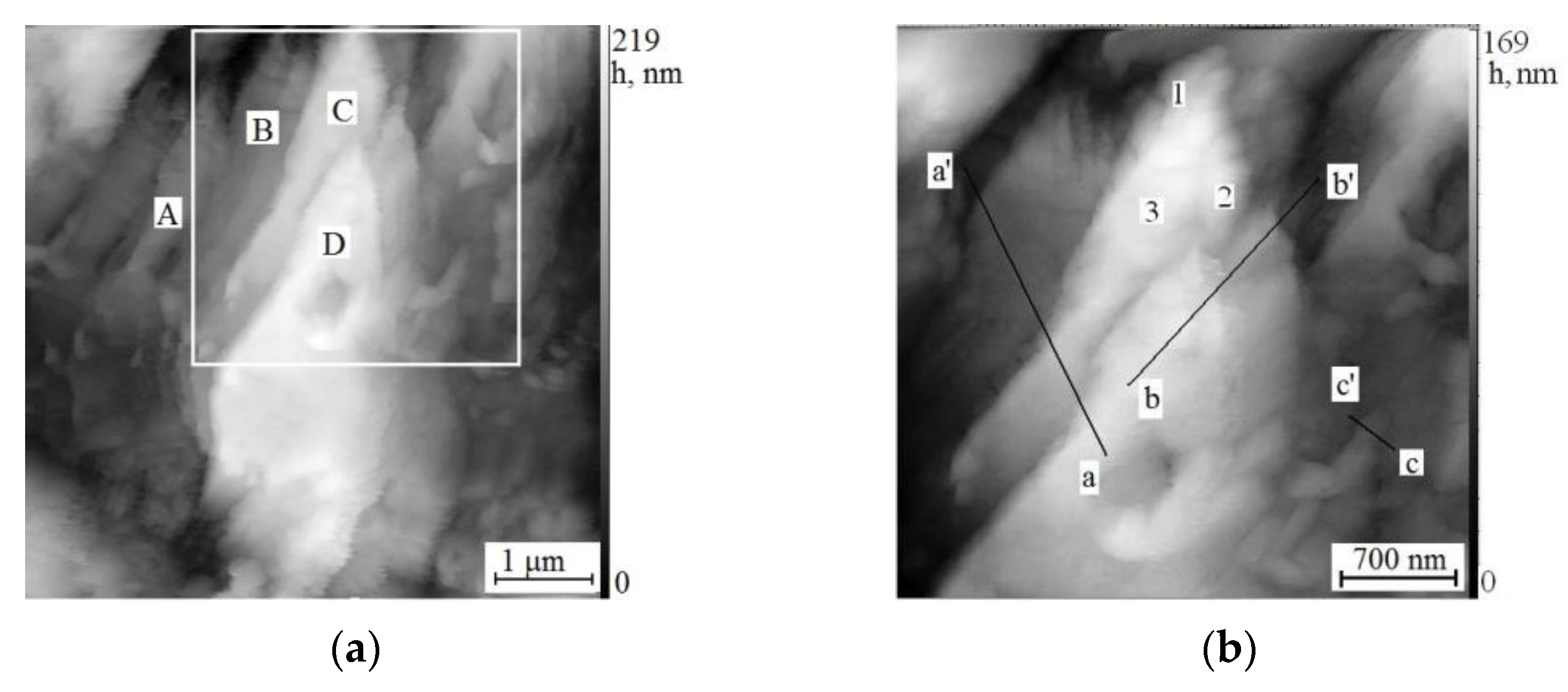
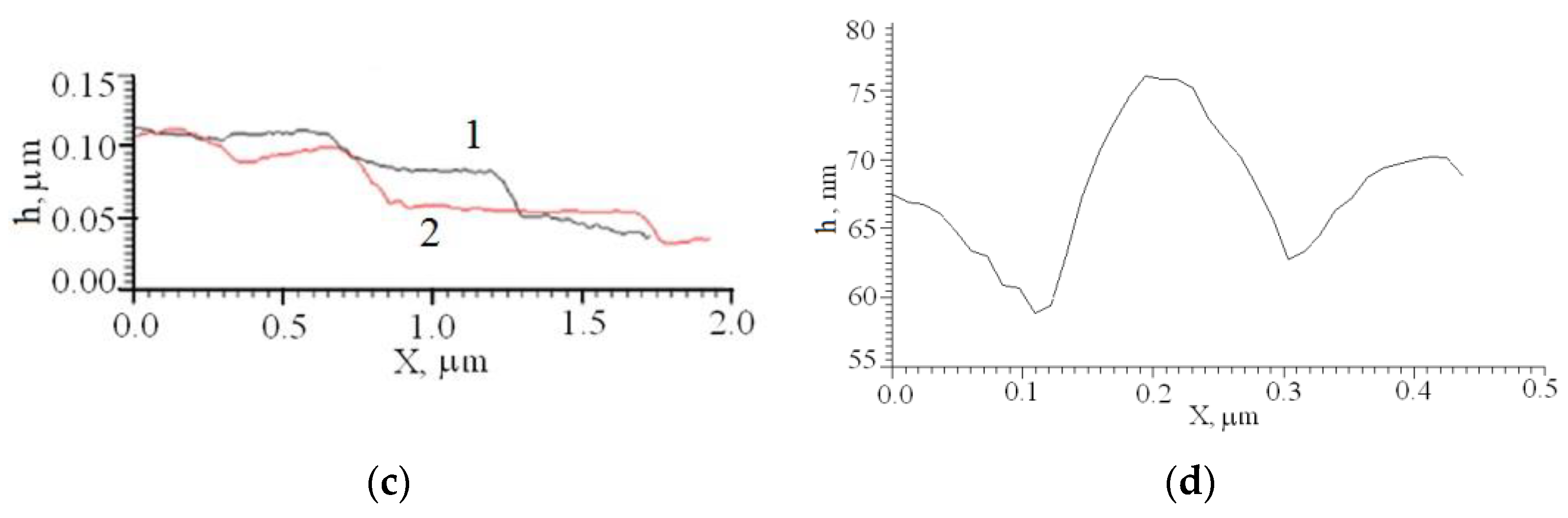
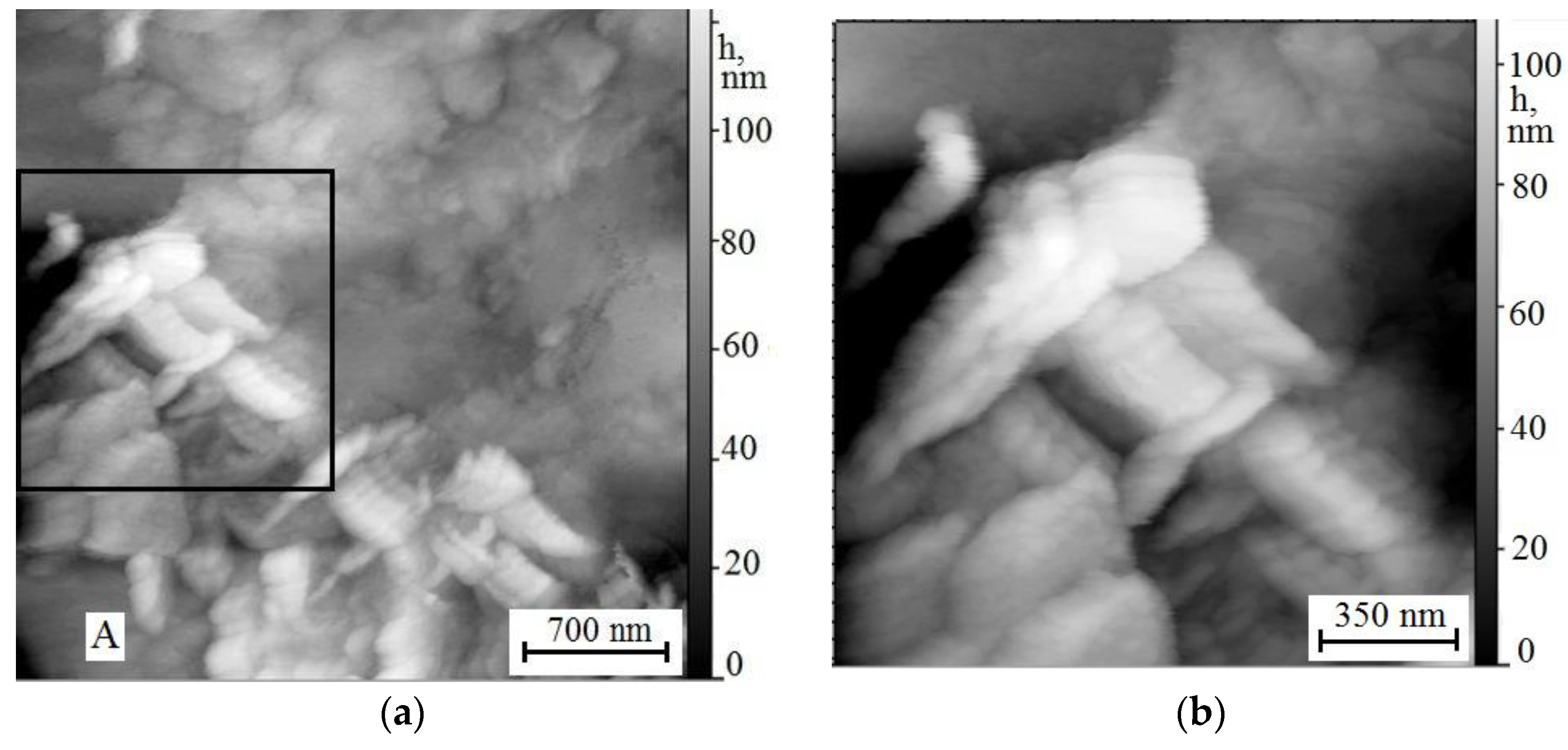
3.3. Scanning Tunneling Microscopy

Scanning tunneling microscopy of coatings reveals a wide range of ferrite–carbide microstructures of various morphologies, which cannot be detected by optical microscopy due to insufficient resolution. The fine microstructure of the coatings deposited with the modified and commercial electrodes differs significantly, which suggests the effect of the nanodispersed titanium carbonitride additive on the austenite decomposition process.
It was previously found [33] that the coatings deposited with commercial electrodes have oriented dendritic colonies with the secondary dendrite arm spacing l~50 nm, which determine the crystallization rate and precipitation of carbide particles 50–200 nm in size at grain boundaries. In individual grains, oriented lamellar pearlitic colonies were observed, with the spacing between ferrite and cementite plates Δa = ~200–300 nm [33].
Scanning tunneling microcopy exhibits various structures in the coatings modified by titanium carbonitride nanoparticles, which are not observed in the coatings deposited with commercial electrodes. Among them are finely dispersed structures of lower bainite and acicular ferrite, which are responsible for an increase in fracture toughness. The STM study performed in [33] for the coating modified by 0.15% TiCN disclosed the formation of a structure identified by morphological features as lower bainite. The authors of [34] found fine structures of acicular ferrite and granular bainite in the coating with 0.15% TiCN in the zone that controls crack propagation and fracture toughness of the surface-modified specimen. The observed structures are favorable to an increase in mechanical properties [15].
Figure 4a presents two stitched STM images of the structure observed in the coating with 0.2 wt% TiCN, and Figure 4b shows a cross-sectional profile along line AB shown in Figure 4a. One can see an acicular structure (subunit [15,21]) in the central part of the figure and a coarse particle with the cross-sectional dimension more than 1 μm at the grain boundary in the upper part of the figure.
The needle exhibited in Figure 4a has a length of about 3.5 μm and a width at its base of ~370 nm. The needle base is adjacent to the grain boundary, and the needle point is directed to the opposite boundary of the ferrite grain close to the precipitated particle. Thus, the size of the needle subunit turns out to be limited by the ferrite grain size. From Figure 4a it is seen that a thin substructure forms along both sides of the needle near its point, which will be discussed later. The cross section of the needle subunit (Figure 4b) has a tent-like profile, which is slightly distorted due to the thin substructure on its sides. The thin substructure appears as a plateau in the profile, which is ~150–200 nm long on either side of the needle subunit and 30–35 nm below the needle point. Valleys are evident between the thin substructure and the surrounding ferrite, which are lowered by ~25 nm from the plateau level.
Figure 5a shows a higher-resolution image of the upper thin part of the needle, and Figure 5b plots a cross-sectional profile along the longitudinal axis of the needle marked by line CD in Figure 5a. The needle subunit is seen to have an interesting morphological feature: it is not monolithic but consists of thin plates, which coalesce into the needle. The plates lie at a certain angle relative to the needle growth direction. In the cross section (Figure 5b), the plates form a quasi-periodic relief with ridges from 2–3 to 10 nm in height and about 100 nm in length.
The fine substructure found on the sides of the needle (Figure 5a) represents a series of extended protrusions that can be taken either as a monolithic continuation of the needle or as a series of separate particles laterally in contact with each other. Protrusions have the length from several tens to several hundreds of nm and the thickness ~50 nm decreasing with distance from the side surface of the needle. The longitudinal axes of the protrusions on either side of the needle make the same angle to the needle growth direction (Figure 5a). From the analysis of the STM image (Figure 5), we can conclude that the apparent angle of the protrusions to the needle growth direction is ~60° on the left side of the needle and ~70–80° on the right side. The protrusion orientation is sure evidence for the role of crystallographic factors in the formation of the thin substructure of the needle, pointing to the fulfillment of the orientation relationships between austenite and its products.
Let us analyze morphological features of the observed needle subunit. Such a needle-like shape is typical of both acicular ferrite and lower bainite structures, which have the same transformation mechanisms but differ in the site of their nucleation and carbide precipitation [15]. Lower bainite nucleates at the boundaries of austenite grains, while acicular ferrite is characterized by intragranular nucleation on nonmetallic inclusions [15]. Since both structures grow by the diffusionless mechanism with the carbon redistribution into austenite after transformation, bainite or acicular ferrite subunits do not cross the boundaries of austenite grains. In Figure 4, the needle subunit is seen to nucleate near the grain boundary and not to cross the grain boundary during its growth.
The profile of the relief formed on the surface of the pre-polished specimens during austenite decomposition at the stages of intermediate and martensitic phase transitions is helpful in clarifying the transformation mechanism of austenite [15,25,35]. It is believed [15] that the diffusion mechanism of lath and plate formation during the austenitic–ferritic transformation results in a tent-like profile, while the displacive mechanism provides an asymmetric N-shaped profile. However, it was shown in [36] that the displacive mechanism of bainite formation can also lead to a tent-like cross-sectional profile provided that the habit plane is perpendicular to the specimen surface and there is a weakly accommodating matrix on both sides of the relief. In our work, the acicular structure shown in Figure 5 has a tent-like cross-sectional profile, which will be detailed below.
The hierarchical structure of lower bainite subunits was observed with TEM and STM in various alloys [21,35,36,37,38,39,40,41], and several mechanisms for its formation were proposed and discussed [15,39].
In [38], it was suggested that thickening of a bainite sheaf occurs due to the nucleation of thin bainite plates in adjacent positions. According to [21], first, the initiating ferrite plate appears, which is called the “spine”, and then other ferrite crystals sympathetically nucleate at it, thus forming a bainite subunit. The authors of [21] report that the sympathetic nucleation of ferrite crystals often occurs only on one of the two broad faces of the “spine”. These crystals, whose morphology often seems to be close to the thick plate morphology, are often at a significant angle to the “spine”. Thus, one side of the subunit remains smooth, while teeth are observed on the other side near the tip of the lower bainite sheaf. They are formed due to uneven elongation of individual “secondary plates”, which possibly originated at different times [21].
However, as was shown in [36,42], lower bainite subunits in low- and medium-carbon alloyed steels consist of packets of bidirectional ferrite sublaths. In this case, both sides of the subunit may be unsmooth, as in Figure 4a and Figure 5a. It was also reported in [36,42] that uniform face-to-face displacement of two groups of packets in two directions leads to the formation of a tent-like relief, which also agrees with our observations (Figure 4b).
Thus, from the morphological analysis we can conclude that the acicular structure observed in Figure 4 and Figure 5 is a lower bainite subunit, which increases fracture toughness and strength of the steel and refers to mechanically favorable structures.
Figure 6a,b exemplify the structure observed with STM in the coating deposited with the experimental electrode containing 0.25 wt% TiCN. Figure 6c,d plot the cross-sectional profile along lines a-a’, b-b’, and c-c’ shown in Figure 6b. Figure 6b exhibits an enlarged image of the region squared in Figure 6a. Figure 6a shows a packet of wedge-shaped plates marked A, B, C, and D, which grow from the grain boundary partly visible in the lower left part of the figure. Plate C consists of subplates 1, 2, and 3 (Figure 6b). These results indicate a hierarchically organized structure of the plates. It consists of structural units of different scales such as sub-subunits [28,29], which are formed in the material during surfacing. A hierarchical structure of lower bainite sub-sub-subunits was previously observed with STM in various steels [28,29], which counts in favor of a sympathetic mechanism of nucleation and growth of lower bainite.
Figure 6c (curves 1 and 2) presents cross-sectional profiles of plates along lines a-a’ and b-b’ shown in Figure 6b. It can be seen (Figure 6c) that the cross sections of plates D, C, and B (curve 1) and D and C (curve 2) have terraces about 500 nm long, which end in steps, being about 30–50 nm above the terrace of the next plate.
An additional argument in favor of a sympathetic mechanism of nucleation and growth of the observed plates was found from the analysis of cross-sectional profiles of the smallest structural unit of an individual plate and of a packet of plates. According to the STM study of bainite [28,29], there is no one-to-one correspondence between the surface relief and an individual bainite plate. The surface relief is usually composed of groups of small relief forms, which correspond to subplates, subunits, and sub-subunits. Therefore, only the surface relief associated with the smallest structural units proves to be undistorted and gives an idea of the mechanism of phase transformation. The surface relief c-c’ in Figure 6c, which is associated with the smallest structural unit, is closer to a tent-like shape than the N-like shape induced by invariant plane deformation for martensite. This indicates the sympathetic mechanism of the formation and growth of lower bainite in the coating [28,29].
The observed shape of the plate profile along line c-c’ (Figure 6d) is consistent with the mechanism of face-to-face sympathetic nucleation and stepwise growth of lower bainite plates proposed in [35]. According to this mechanism [35], the nucleus of a new phase has a common face with the matrix from the very beginning, and the interphase boundary is semicoherent, which ensures its low energy and immobility in the perpendicular direction. Plates grow due to the migration of their vertical walls, which become incoherent, for example, due to thermal activation. The growth rate of the bainite plate is controlled by the composition gradient and volumetric diffusion of dissolved carbon atoms in the matrix near the interface. Another new phase may nucleate on the broad face after the incubation time, and the process is repeated, ending in the formation of a new bainite plate. Thus, a packet of plates forms as a result of the competition of two processes: their nucleation and growth [35].The wedge shape of the plates (Figure 6a,b) is due to a gradual decrease in the carbon concentration in austenite near the phase boundary as the bainite plate grows, as well as due to the accumulation of elastic deformation at the ferrite–austenite interface.
Thus, the morphological analysis of the plate based on the STM data suggests that the observed structure is lower bainite, which is formed by the mechanism of face-to-face sympathetic nucleation and growth [34].
STM images of the coating with ~1 wt% TiCN nanoparticles display the acicular structure of a slightly different morphology (Figure 7a,b). Figure 7b shows a magnified image of regions squared in Figure 7a. The microstructure is seen to be composed of a series of acicular crystals from several hundred nm to ~2 μm in length and ~150–200 nm in thickness. The thick end (~350 nm) of the largest acicular crystal (Figure 7a,b) is adjacent to a polyhedral particle with an average diameter of about 350 nm. The particle size is within the minimum size (~0.3–0.5 µm) necessary for the particle to be the nucleus of a new phase [43]. Therefore, the particle can be assumed to be the nucleus of the observed structure.
Acicular crystals have a rather uniform contrast in the STM images, which may indicate their homogeneous chemical composition, without precipitates, such as carbides. This may be explained by diffusionless transformation by shear deformation relative to the invariant plane, when the transformation products (ferritic plates of acicular ferrite or martensite) inherit the chemical composition of the parent austenite [15]. Most of the acicular crystals in Figure 7a have a common orientation, which probably indicates the influence of the crystallographic factor on their formation, although the orientation of individual crystals (marked with the letter A in Figure 7a) differs.
Acicular ferrite is characterized by intragranular nucleation of crystals, although the direction of their growth is usually chaotic [15]. However, intragranular nucleation and growth of parallel laths of acicular ferrite was observed during continuous cooling of low-carbon microalloyed steel [44]. Along with a group of parallel laths, a significant number of differently oriented laths were observed. The laths of acicular ferrite were much smaller than those in ordinary bainite packets, which created a small-scale structure of acicular ferrite [44].
At higher magnification in Figure 7b, itis seen that the largest acicular crystal consists of three parts of approximately the same shape and size. Moreover, similarly oriented acicular crystals have bridges formed of a series of thin plates (~100–150 nm in thickness) almost aligned with the longitudinal axis of the acicular crystals. The dimensions (length and width) of acicular crystals decrease with distance from the largest acicular crystal (Figure 7a,b). The observed structural features may point to its autocatalytic nucleation [45].
Autocatalytic nucleation is usually associated with martensitic transformation [45]. Autocatalysis is caused by the accumulation of strain energy and defects at the interface between the product and parent phases under plastic deformation of austenite due to the volume mismatch of the γ/α phases. Deformed austenite in front of the growing ferrite makes a larger contribution to the ferrite nucleation than undeformed austenite. Thus, the occurrence of repeated nucleation of ferrite in front of the moving interface can lead to bursts of nucleation and growth of ferrite plates [45].
According to [15], the role of autocatalysis in the bainitic transformation is less significant than that in the martensitic transformation. The bainitic transformation occurs at a lower driving force, when defects induced by transformation do not play such a decisive role in stimulating further nucleation.
An alternative explanation of formation of the structures observed in Figure 7a,b is sympathetic nucleation [35]. If bridges between acicular crystals are taken not as separate ferrite plates but as continuously connected parts of the growth front of the initial nucleus, which is the largest needle, the observed acicular crystals can result from sympathetic nucleation and growth of bainite (Figure 7a,b). In this case, the growth of a new needle resumes only after a part of carbon is redistributed from ferrite to austenite. Most likely it nucleates at the site where pinning by dislocation debris is minimum and where the driving force is maximum due to the rapid dispersion of carbon rejected to austenite [45].
The morphology seen in Figure 7a,b can belong to lower bainite and acicular ferrite or martensite. The small size of the structural elements bears witness to their formation at a high cooling rate. Although it is difficult to unambiguously interpret the nature of the structure based on the available STM data, its thin internal microstructure will have a positive effect on fracture toughness by decreasing the elementary crack path.

3.4. Transmission Electron Microscope

Specimens with coatings modified by 0.15 wt% TiCN nanoparticles, which demonstrate the highest fracture toughness and reveal morphological signs of lower bainite under STM, are studied using a transmission electron microscope in the imaging and diffraction modes. Intermediate transformation structures of an acicular or lamellar type were not seen on coatings during the TEM study, which is probably due to their locality and low content. However, evidence of the formation of iron oxide and metastable ε carbide was found.
Figure 8a shows a typical bright-field image of the α-ferrite structure, for which the selected area diffraction pattern is obtained (Figure 8b) with the direction of the incident beam parallel to the most important axes of the matrix zones. Figure 8a shows equally oriented plates or laths several nm wide and several tens to a hundred nm long. The electron diffraction pattern obtained from this section of the structure contains α-phase diffraction reflections belonging to the [110], [134], [320] zone axes, of which only the lattice with the [110] zone axis is shown in Figure 8b. In addition, Figure 8b shows sixth-order symmetry diffraction spots regularly ordered with respect to the diffraction spots of the matrix, which indicates that the crystal phases are coherent with the matrix.
Comparison of the interplanar spacings for diffraction spots with hexagonal symmetry with the interplanar spacings of the compounds listed in the JCPDS (Joint Committee on Powder Diffraction Standards) file showed that hexagonal iron oxide Fe0.98O with lattice parameters a = 2.901 Å and c = 7.532 Å is closest to the experimental value. The zone axis of the oxide is [001].
The tabulated data point to a good agreement between the calculated and measured values of interplanar distances and angles of α-Fe and iron oxide. The [011] α-Fe zone axis and the [ 1 ¯ 1 ¯ 0 ] iron oxide Fe0.98O zone axis parallel to it are determined based on the indexed reflections (Figure 8b). The (1 1 ¯ 0 ) plane of α-Fe is parallel to the (1 1 ¯ 0 ) plane of iron oxide.
The measurement of interplanar spacings belonging to weak diffraction reflections and the angles between them made it possible to identify the ε-carbide with the zone axis [ 1 ¯ 1 ¯ 0 ] (Figure 8b). In addition, weak reflections (30 1 ¯ ) and (012) of ε-carbide with the zone axis [1 6 ¯ 3] are also identified in the electron diffraction pattern. The diffraction pattern has additional unindexed reflections, which are possibly due to double diffraction from carbides and the matrix as well as from carbide precipitates of other types.
The calculated value of the parameter c = 4.36 Å for ε-carbide agrees satisfactorily with the literature data c = 4.349 Å [45], while the lattice parameter a = 2.965 Å significantly exceeds the corresponding value a = 2.754 Å [45]. This may be due to the fact that ε-carbide is additionally alloyed with other elements, such as, for example, titanium. This issue deserves a special detailed study.
Crystallographic studies of the carbide formation in silicon-containing steels after a special thermomechanical treatment were performed in [46,47,48,49]. They dealt with the description of structural sequence during carbide transformation in these steels, the explanation of transformation mechanisms, and the determination of the main orientation relationships between carbides and the matrix. It was shown [46] that the cementite formations are preceded by the formation of metastable carbides, whose composition and structure change with the time of isothermal holding and depend on the steel composition. According to [47], the precipitation of ε-carbide in silicon-containing steels during isothermal holding at 275 ºC occurs directly from austenite even at low temperatures and particular carbide morphology results from precipitation along the austenite/ferrite interface.
As shown in [46,47,49], ε-carbide is the first to form in the low-temperature region of bainite formation, which is replaced by cementite during further transformation. Therefore, the result of our TEM study indirectly confirms that the introduction of the modifying TiCN additive into electric arc coatings on low-carbon steel shifts the austenitic–ferritic transformation to the region of intermediate temperatures.

4. Discussion

The results of optical microscopy of the coating structure show that the introduction of titanium carbonitride nanoparticles with the estimated concentration from 0.15 to 1 wt% leads to a significant refinement of the ferrite–pearlite structure compared with the coatings deposited with commercial electrodes. Variation in the concentration of titanium carbonitride nanoparticles in the studied range proves to have little effect on the grain size of the ferrite–pearlite structure. Grain refinement is responsible for an increase in strength characteristics due to grain boundary strengthening and fracture toughness due to crack retardation.
Scanning tunneling microscopy reveals that ferrite grains contain local regions with highly dispersed intermediate transformation structures of the acicular or lamellar type. High dispersity of acicular structures indicates that their formation occurs at a high rate of continuous cooling. By morphological features, the observed structures are identified as packets of lower bainite plates or subunits of lower bainite or acicular ferrite. The basis for the identification of structures is the works devoted to the thorough STM and TEM investigation of lower bainite structures formed in special modes of isothermal holding of certain model specimens [21,25,35,36,37]. The analysis of morphological features of acicular and lamellar structures and the available literature data allow us to make assumptions about the mechanisms of their formation. The conclusion from the results of this and previous papers [33,34] is that an almost twofold increase in the fracture toughness of the “substrate-modified surface” compositions with titanium carbonitride additives over the fracture toughness of the compositions obtained using commercial electrodes is of a complex nature. The leading role in improving the fracture toughness probably belongs to grain refinement. Highly dispersed acicular and lamellar structures within ferrite grains also contribute to structure refinement and are favorable for the increase in fracture toughness of the “substrate-modified surface” composition, which, however, have a secondary effect.

Author Contributions

Conceptualization, K.P. and G.N.; methodology, K.P.; validation, K.P.; formal analysis, G.N.; investigation, K.P. and P.Y.; resources, K.P., G.N. and P.Y.; data curation, K.P. and G.N.; writing—original draft preparation, K.P.; writing—review and editing, K.P. and G.N.; visualization, K.P. and P.Y.; supervision, K.P.; project administration, G.N.; and funding acquisition, K.P. All authors have read and agreed to the published version of the manuscript.

Funding

The work was performed within the government statement of work for ISPMS SB RAS, research line FWRW-2021-0009.

Institutional Review Board Statement

Not applicable.

Informed Consent Statement

Not applicable.

Data Availability Statement

The data presented in this study are available on request of the corresponding author. The data are not publicly available due to a proper institutional repository policy.

Acknowledgments

The authors would like to express their gratitude to O.B. Perevalova, N.V. Girsova, N.A. Narkevich, and A.I. Gordienko for help in the analysis of experimental data and helpful discussions.

Conflicts of Interest

The authors declare no conflict of interest. The funders had no role in the design of the study, in the collection, analysis or interpretation of data, in writing of the manuscript, or in the decision to publish the results.

References

  1. Roy, M. (Ed.) Surface Engineering for Enhanced Performance against Wear; Springer: Berlin/Heidelberg, Germany, 2013; 319p. [Google Scholar]
  2. Ellis, T.; Garrett, G.G. Influence of Process Variables in Flux Cored Arc Welding of Hardfacing Deposits. Surf. Eng. 1986, 2, 55–66. [Google Scholar] [CrossRef]
  3. Singh, M.; Bhagi, L.K.; Arora, H. Effects of Shielded Metal Arc Welding Process Parameters on Dilution in Hardfacing of Mild Steel Using Factorial Design. In Advances in Materials Processing. Lecture Notes in Mechanical Engineering; Singh, S., Prakash, C., Ramakrishna, S., Krolczyk, G., Eds.; Springer: Singapore, 2020; pp. 207–220. [Google Scholar] [CrossRef]
  4. Dorval, D.C.A.; Tavares, J.R. Photo-Initiated Chemical Vapour Deposition as a Scalable Particle Functionalization Technology (A Practical Review). Powder Technol. 2013, 239, 484–491. [Google Scholar] [CrossRef] [Green Version]
  5. Selvakumar, N.; Barshilia, H.C. Review of physical vapor deposited (PVD) spectrally selective coatings for mid- and high-temperature solar thermal applications. Sol. Energy Mater. Sol. Cells 2012, 98, 1–23. [Google Scholar] [CrossRef]
  6. Acciari, H.A.; Palma, D.P.S.; Codaro, E.N.; Zhou, Q.; Wang, J.; Ling, Y.; Zhang, J.; Zhang, Z. Surface modifications by both anodic oxidation and ion beam implantation on electropolished titanium substrates. Appl. Surf. Sci. 2019, 487, 1111–1120. [Google Scholar] [CrossRef]
  7. Diankun, L.; Bo, G.; Guanglin, Z.; Jike, L.; Liang, H. High-Current Pulsed Electron Treatment of Hypoeutectic Al-10Si Alloy. High Temp. Mater. Process. 2017, 36, 97–100. [Google Scholar] [CrossRef]
  8. Katipelli, L.R.; Dahotre, N.B. Mechanism of high temperature oxidation of laser surface engineered TiC/Al alloy composite coating on 6061 aluminium alloy. Mater. Sci. Technol. 2001, 17, 1061–1068. [Google Scholar] [CrossRef]
  9. Liu, J.; Sun, J.; Wei, S.; Lu, S. The Effect of Nickel Contents on the Microstructure Evolution and Toughness of 800 MPa Grade Low Carbon Bainite Deposited Metal. Crystals 2021, 11, 6–709. [Google Scholar] [CrossRef]
  10. Atamert, S.; Bhadeshia, H.K.D.H. Comparison of the microstructures and abrasive wear properties of stellite hardfacing alloys deposited by arc welding and laser cladding. Metall. Mater. Trans. A 1989, 20, 1037–1054. [Google Scholar] [CrossRef]
  11. Hedenqvist, P.; Olsson, M.; Hogmark, S. Characterisation of Ti(C,N) and TiN Coatings on Powder Metallurgy High Speed Steels. Surf. Eng. 1992, 8, 39–47. [Google Scholar] [CrossRef]
  12. Artem’ev, A.A. Influence of microparticles of titanium diboride and nanoparticles of titanium carbonitride on the structure and properties of the deposited metal. MiTOM 2011, 12, 32–37. [Google Scholar]
  13. Golovko, G.G.; Kostin, V.A.; Grigorenko, G.M. Peculiarities of the influence of complex alloying on structure formation and mechanical properties of welds on low-alloyed high- strength steels. Paton Weld. J. 2011, 7, 11–17. [Google Scholar]
  14. Dong, J.; Liu, C.; Liu, Y.; Li, C.; Guo, Q.; Li, H. Effects of two different types of MX carbonitrides on austenite growth behavior of Nb-V-Ti microalloyed ultra-high strength steel. Fusion Eng. Des. 2017, 125, 415–422. [Google Scholar] [CrossRef]
  15. Bhadeshia, H.K.D.H. Bainite in Steels: Transformations, Microstructure and Properties, 2nd ed.; The University Cambridge Press: Cambridge, UK, 2001; 454p. [Google Scholar]
  16. Krauss, G.; Thomson, S.W. Ferritic Microstructures in Continuously Cooled Low- and Ultralow- carbon Steels. ISIJ Int. 1995, 35, 937–945. [Google Scholar] [CrossRef]
  17. Kang, J.S.; Seol, J.-B.; Parc, C.G. Three-dimensional characterization of bainitic microstructures in low-carbon high-strength low-alloy steel studied by electron backscatter diffraction. Mater. Charact. 2013, 79, 110–121. [Google Scholar] [CrossRef]
  18. Araki, T.; Enomoto, M.; Shibata, K. Microstructural Aspects of Bainitic-like Ferritic Structures of Continuously Cooled Low Carbon (<0.1%) HSLA Steels. Mater. Trans. JIM 1991, 32, 729–736. [Google Scholar] [CrossRef] [Green Version]
  19. Bamfitt, B.L.; Speer, J.G. Perspective on the morphology of bainite. Metall Mater. Trans. A 1990, 21, 817–829. [Google Scholar] [CrossRef]
  20. Wilson, E.A. The γ→α-transformation in low-carbon irons. ISIJ Int. 1994, 34, 615–630. [Google Scholar] [CrossRef]
  21. Spanos, G.; Fang, H.S.; Aaronson, H.I. A Mechanism for the Formation of Lower Bainite. Metall Mater. Trans. A 1990, 21, 1381–1390. [Google Scholar] [CrossRef]
  22. Bo, X.Z.; Fang, H.S. Surface relief effects associated with the formation grain boundary allotriomorph in an Fe–C alloy. Acta Mater. 1998, 46, 2929–2936. [Google Scholar] [CrossRef]
  23. Yang, H.G.; Wang, J.J.; Li, C.M.; Fang, H.S.; Zheng, Y.K. Ledges in Widmanstatten ferrite observed by scanning tunneling microscopy. J. Mater. Sci. Lett. 1998, 17, 331–333. [Google Scholar] [CrossRef]
  24. Yan, J.; Yu, H.; Ge, Z.; Huang, Y.; Fang, H.; Wang, J.; Yang, Z.; Deng, X. Scanning tunneling microscopy investigation of bainite in steel. J. Vac. Sci. Technol. B 1994, 12, 1793–1796. [Google Scholar] [CrossRef]
  25. Yang, Z.G.; Zhang, C.; Bai, B.Z.; Fang, H.S. Observation of bainite surface reliefs in Fe–C alloy by atomic force microscopy. Mater. Lett. 2001, 48, 292–298. [Google Scholar] [CrossRef]
  26. Fang, H.S.; Yang, J.B.; Yang, Z.G.; Bai, B.Z. The mechanism of bainite transformation in steels. Scr. Mater. 2002, 47, 157–162. [Google Scholar] [CrossRef]
  27. Swallow, E.; Bhadeshia, H.K.D.H. High resolution observations of displacements caused by bainitic transformation. Mater. Sci. Tech. 1996, 12, 121–125. [Google Scholar] [CrossRef]
  28. Wang, J.J.; Fang, H.S.; Yang, Z.G.; Zheng, Y.K. Fine Structure and Formation Mechanism of Bainite in Steels. ISIJ Int. 1995, 35, 992–1000. [Google Scholar] [CrossRef] [Green Version]
  29. Wang, J.J.; Fang, H.S.; Zheng, Y.K.; Yang, Z.G. Use of scanning tunneling microscopy in metallography. Mater. Charact. 1994, 33, 169–174. [Google Scholar] [CrossRef]
  30. Bergeon, N.; Kajiwara, S.; Kikuchi, T. Atomic force microscopy study of stress induced martensite formation and its reverse transformation in a thermomechanically treated Fe-Mn-Si-Cr-Ni alloy. Acta Mater. 2000, 48, 4053–4064. [Google Scholar] [CrossRef]
  31. Girault, E.; Jacques, P.; Harlet, P.; Mols, K.; Van Humbeeck, J.; Aernoudt, E.; Delannay, F. Metallographic Methods for Revealing the Multiphase Microstructure of TRIP-Assisted Steels. Mater. Charact. 1998, 40, 111–118. [Google Scholar] [CrossRef]
  32. Nečas, D.; Klapetek, P. Gwyddion: An open-source software for SPM data analysis. Cent. Eur. J. Phys. 2012, 10, 181–188. [Google Scholar] [CrossRef]
  33. Kuznetsov, P.V.; Galchenko, N.K.; Rakhmatulina, T.V.; Samartsev, V.P.; Kolesnikova, K.A.; Laptev, R.S.; Babikhina, M.N. Scanning tunnel microscopy of coatings with titan carbonitride nanoparticles and their properties. AIP Conf. Proc. 2017, 1909, 020114. [Google Scholar] [CrossRef]
  34. Kuznetsov, P.V.; Galchenko, N.K.; Belaeva, I.V.; Kozlova, T.V. Structural Features of the Two-Layer Electric Arc Coating with of Additives of Titanium Carbonitride Nanoparticles on Low-Carbon Steel. Russ. Phys. J. 2021, 64, 605–611. [Google Scholar] [CrossRef]
  35. Fang, H.S.; Wang, J.J.; Yang, Z.G.; Li, C.M.; Zheng, Y.K.; Li, C.X. Formation of Bainite through Sympathetic Nucleation and Ledgewise Growth Mechanism in Ferrous and Nonferrous Alloys. Metall. Mater. Trans. A 1996, 27, 1535–1545. [Google Scholar] [CrossRef]
  36. Sun, J.; Lu, H.; Kang, M. The Nature of Lower Bainite Midrib. Metall. Trans. A 1992, 23A, 2483–2490. [Google Scholar] [CrossRef]
  37. Ohmori, Y.; Ohtsubo, H.; Jung, Y.C.; Okaguchi, S.; Ohtani, H. Morphology of Bainite and Widmanstatten Ferrite. Metall. Mater. Trans. A 1994, 25, 1981–1989. [Google Scholar] [CrossRef]
  38. Ohmori, Y. Crystallographic analysis of lower bainite transformation in Fe-0.7% C alloy. Mater. Trans. JIM 1989, 487–497. [Google Scholar] [CrossRef] [Green Version]
  39. Spanos, G. The Fine Structure and Formation Mechanism of Lower Bainite. Metal. Mater. Trans. A 1994, 25, 1967–1980. [Google Scholar] [CrossRef]
  40. Li, C.M.; Fang, H.S.; Yang, Z.G.; Bo, X.Z.; Wang, J.J.; Zheng, Y.K. Scanning tunnelling microscopy and transmission electron microscopy study of ultrafine structure and surface relief of bainite in a Cu–Zn–Al alloy. J. Mater. Sci. 1998, 33, 487–496. [Google Scholar] [CrossRef]
  41. Fang, H.S.; Wang, J.J.; Zheng, Y.K. Formation Mechanism of Bainitic Ferrite and Carbide. Metall. Mater. Trans. A 1994, 25, 2001–2007. [Google Scholar] [CrossRef]
  42. Yu, D.; Chen, D.; Zheng, J.; He, Y.; Shen, F. Phase Transformation Unit of Bainitic Ferrite And Its Surface Relief In Low And Medium Carbon Alloy Steels. Acta Metall. Sin. (Engl. Ed.) Ser. A 1989, 2, 161–167. [Google Scholar]
  43. Loder, D.; Michelic, S.K.; Bernhard, C. Acicular Ferrite Formation and Its Influencing Factors. A Review. J. Mater. Sci. Res. 2017, 6, 24–43. [Google Scholar] [CrossRef] [Green Version]
  44. Zhang, R.Y.; Boyd, J.D. Bainite Transformation in Deformed Austenite. Metall. Mater. Trans. A 2010, 41, 1449–1459. [Google Scholar] [CrossRef]
  45. Bhadeshia, H.K.D.H.; Christian, J.W. Bainite in Steels. Metall. Trans. A 1990, 21, 767–797. [Google Scholar] [CrossRef]
  46. Dirand, M.; Afqir, L. Identification structural precise des carbures precipites dans les aciers faiblement allies aux divers stades du revenu. Mecanismes de precipitation. Acta. Metall. 1983, 31, 1089–1107. [Google Scholar] [CrossRef]
  47. Huang, D.H.; Thomas, G. Metallography of bainitic Transformation in Silicon Containing Steels. Metall. Trans. A 1977, 8, 1661–1673. [Google Scholar] [CrossRef]
  48. Sandvik, B.P.J. The Bainite Reaction in Fe-Si-C Alloys: The Primary Stage. Metall. Trans. A 1982, 13, 777–787. [Google Scholar] [CrossRef]
  49. Lai, G.Y. On the Precipitation of Epsilon-Carbide in Lower Bainite. Metall. Trans. A 1975, 6, 1469–1471. [Google Scholar] [CrossRef]
Figure 1. Optical images of the coating structure formed using: (a) the commercial electrode; experimental electrodes with the titanium carbonitride content 0.25 wt% (b) and 1 wt% (c).
Crystals 13 00146 g001
Figure 2. Approximation of grain size distribution histograms to the lognormal function in coatings deposited with (a) the commercial electrode (ferrite grains) and (b) electrodes modified by 0.25 wt% TiCN nanoparticles (pearlite grains).
Crystals 13 00146 g002
Figure 3. Ferrite (●) and pearlite (□) grain size as a function of the content of titanium carbonitride nanoparticles in coatings.
Crystals 13 00146 g003
Figure 4. (a) Needle subunit in the coating with 0.2 wt% TiCN; (b) cross-sectional profile along line AB shown in Figure 4a.
Crystals 13 00146 g004
Figure 5. (a) STM image of the thin end of the needle subunit; (b) cross-sectional profile along line CD shown in Figure 5a.
Crystals 13 00146 g005
Figure 6. STM image of the structure of the coating deposited with the experimental electrode containing 0.25% TiCN: (a) packets of plates A, B, C, and D; (b) subunits 1, 2, and 3 of plate C; (c) cross-sectional profiles along lines a-a’ and b-b’ shown in Figure 6b; and (d) cross-sectional profile along line c-c’ shown in Figure 6b.
Crystals 13 00146 g006aCrystals 13 00146 g006b
Figure 7. (a) STM image of the structure of the coating deposited with the experimental electrode containing 1% TiCN: (b) higher-resolution STM image of the region squared in Figure (a).
Crystals 13 00146 g007
Figure 8. (a) Bright-field image of the ferrite structure in the coating with the estimated content of TiCN 0.15 wt%; (b) the corresponding selected diffraction pattern of the region showing the [ 1 ¯ 1 ¯ 0 ] zone axis of ε-carbide and the [00 1 ¯ ] zone axis of iron oxide parallel to the [110] zone axis of α-Fe.
Crystals 13 00146 g008
Table 1. Chemical composition of steel A516-55 (wt%).
CSiMnNiSPCrNCuAsFe
0.10.5–0.81.3–1.7up to 0.30.040.0350.30.0080.30.0896–97
Table 2. Chemical composition of MP-3 electrodes, %.
CMnSiSP
0.100.580.170.0300.035
Table 3. Fracture toughness of samples with coatings deposited with electrodes modified by titanium carboniride additives of different content and commercial electrodes MP-3.
Content of TiCN nanoparticles, wt %0.150.20.251Commercial MP-3 electrode
Fracture toughness of a specimen, J/cm2104- *898642
* Tests for impact strength of compositions with a calculated content of 0.2 wt % TiCN were not carried out. The fatigue life of this composite was 2.7 times higher than the fatigue life of the composite obtained using commercial electrodes.
Disclaimer/Publisher’s Note: The statements, opinions and data contained in all publications are solely those of the individual author(s) and contributor(s) and not of MDPI and/or the editor(s). MDPI and/or the editor(s) disclaim responsibility for any injury to people or property resulting from any ideas, methods, instructions or products referred to in the content.

