
Experimental Study on the Thermal Conductivity of Improved Graphite Composite Insulation Boards


Abstract
1. Introduction
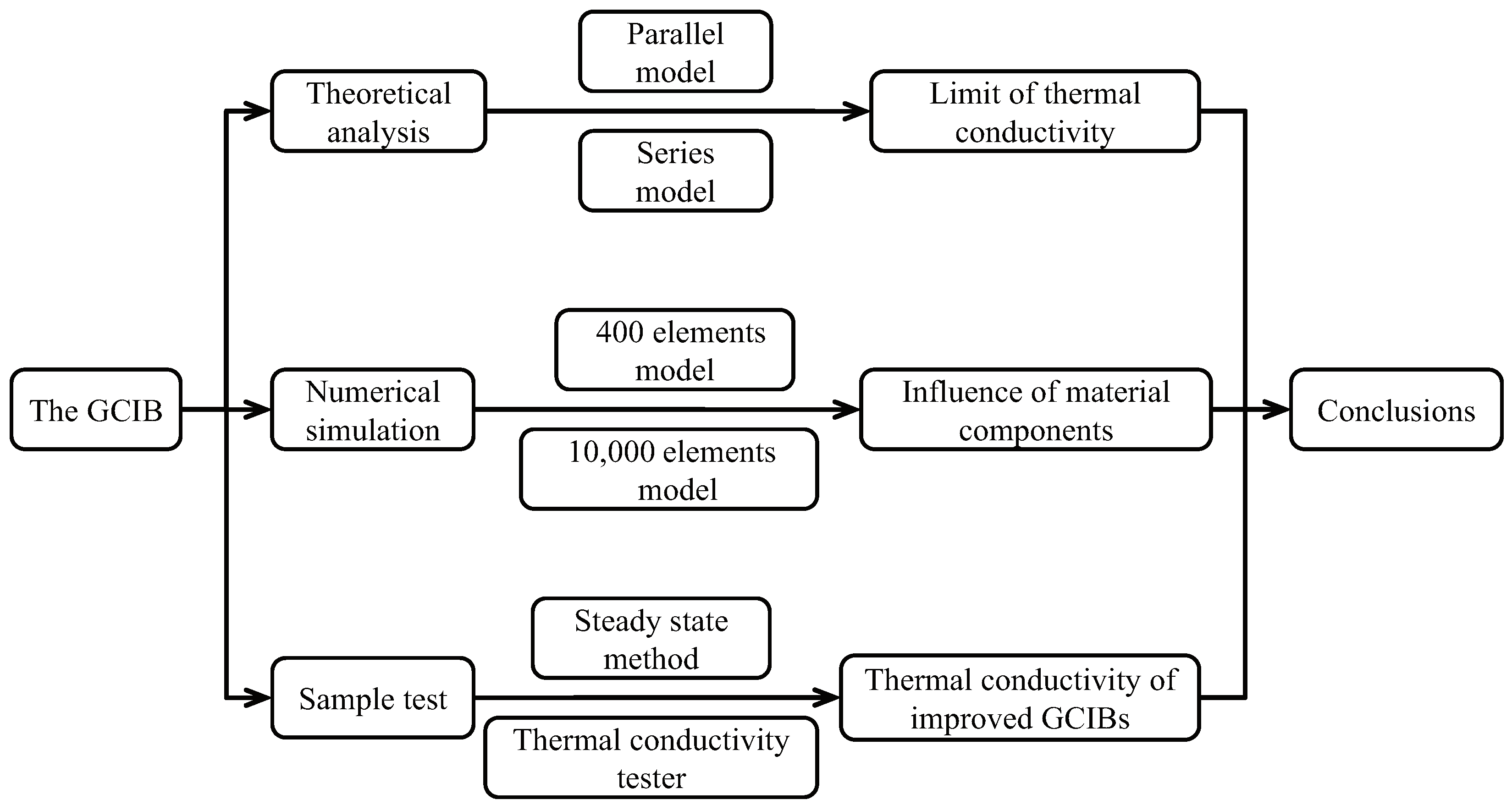
2. Materials and Methods
2.1. Components of the GCIB
- (1)
- Cement
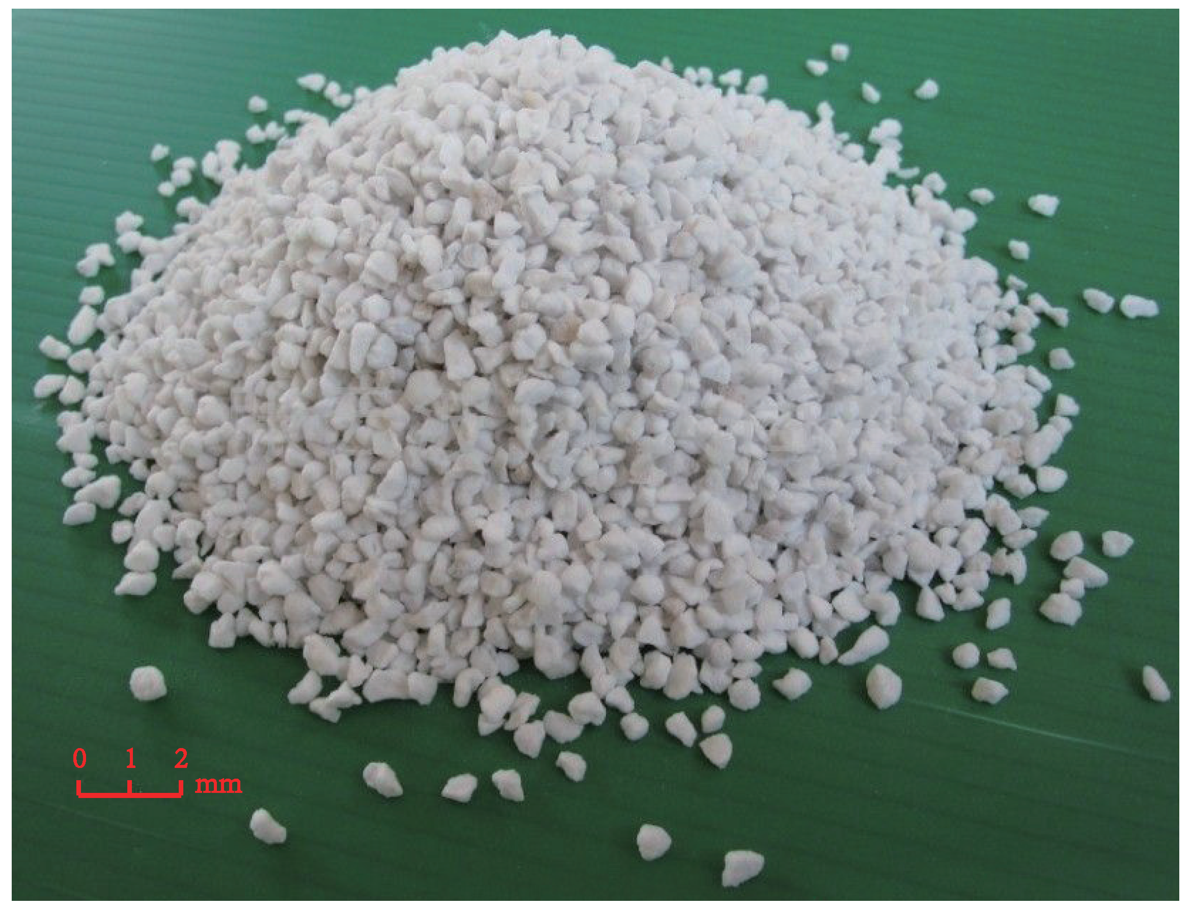
- (2)
- Vitrified microspheres
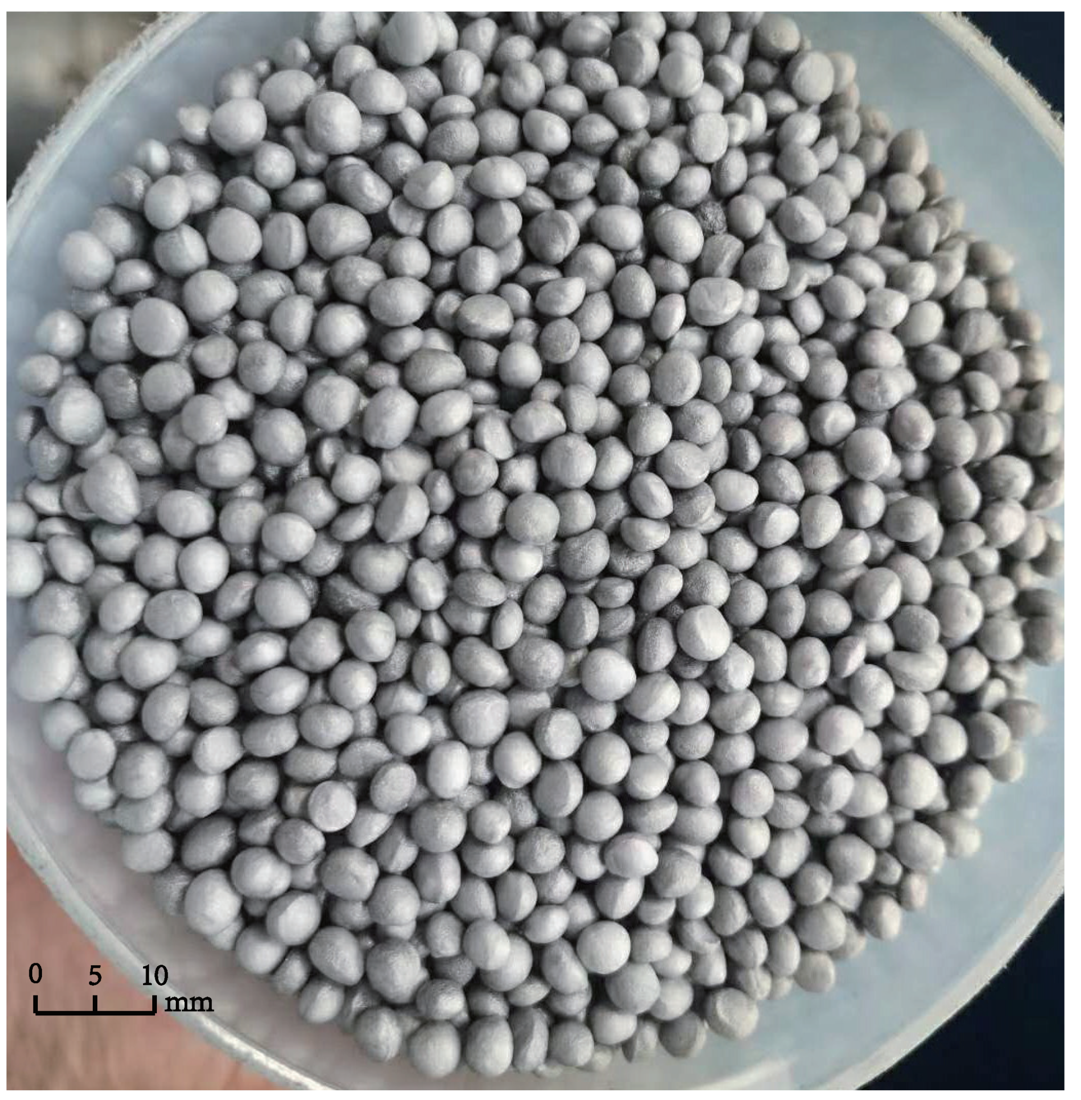
- (3)
- Graphite polystyrene particles
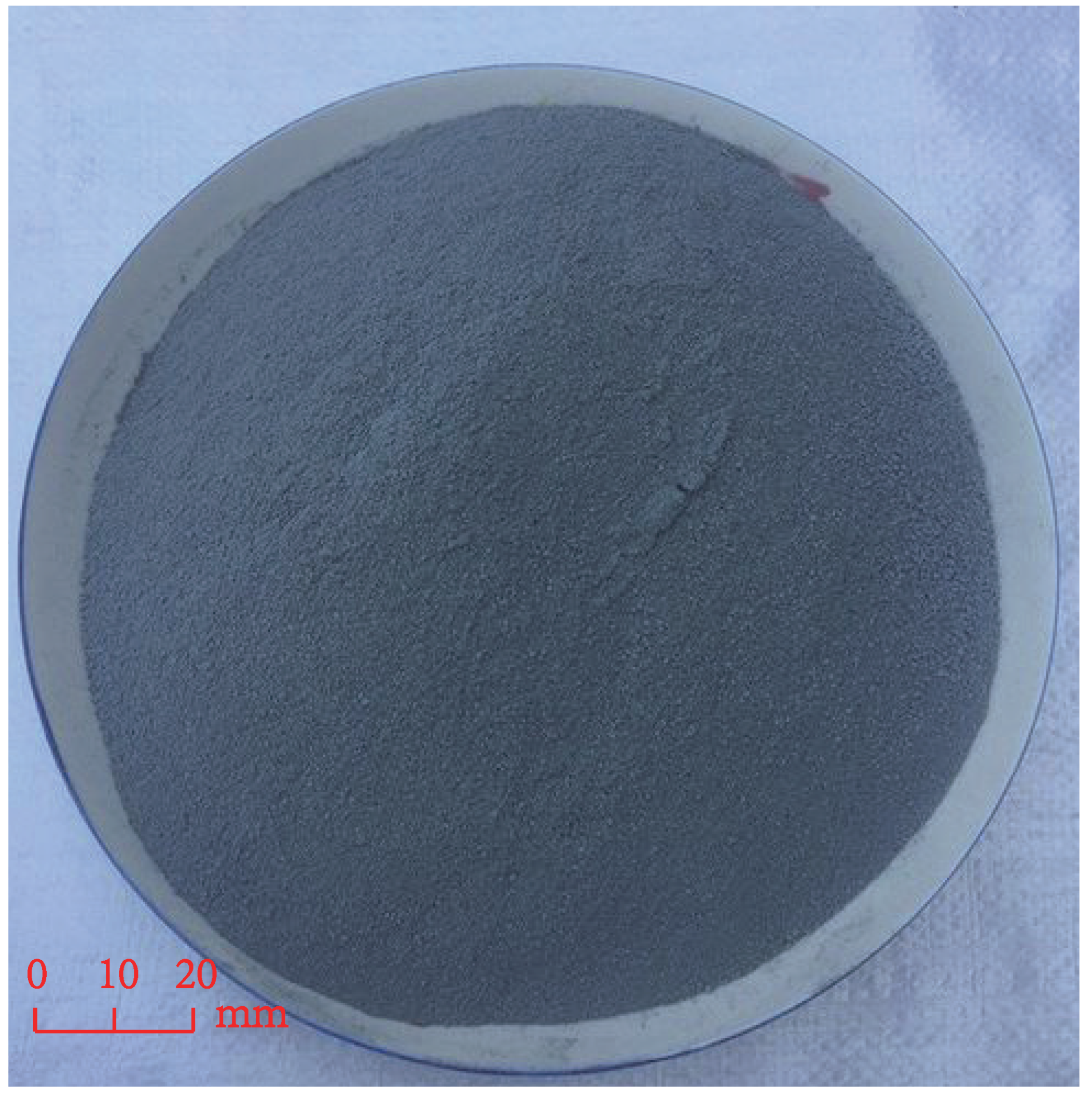
- (4)
- Silica fume
2.2. Methods
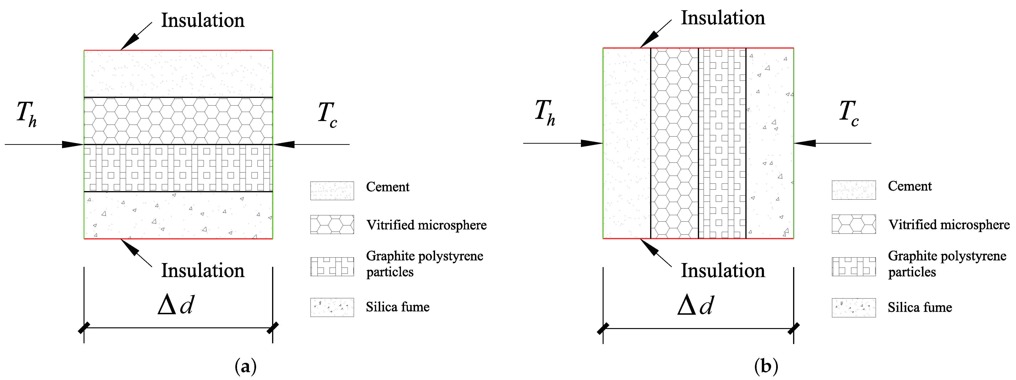
3. Theoretical Analysis of Heat Conduction in the GCIB
- (1)
- Upper limit of thermal conductivity in parallel model of insulation board
- (2)
- Lower limit of thermal conductivity in series model of insulation board
- (3)
- Equivalent thermal conductivity of the GCIB
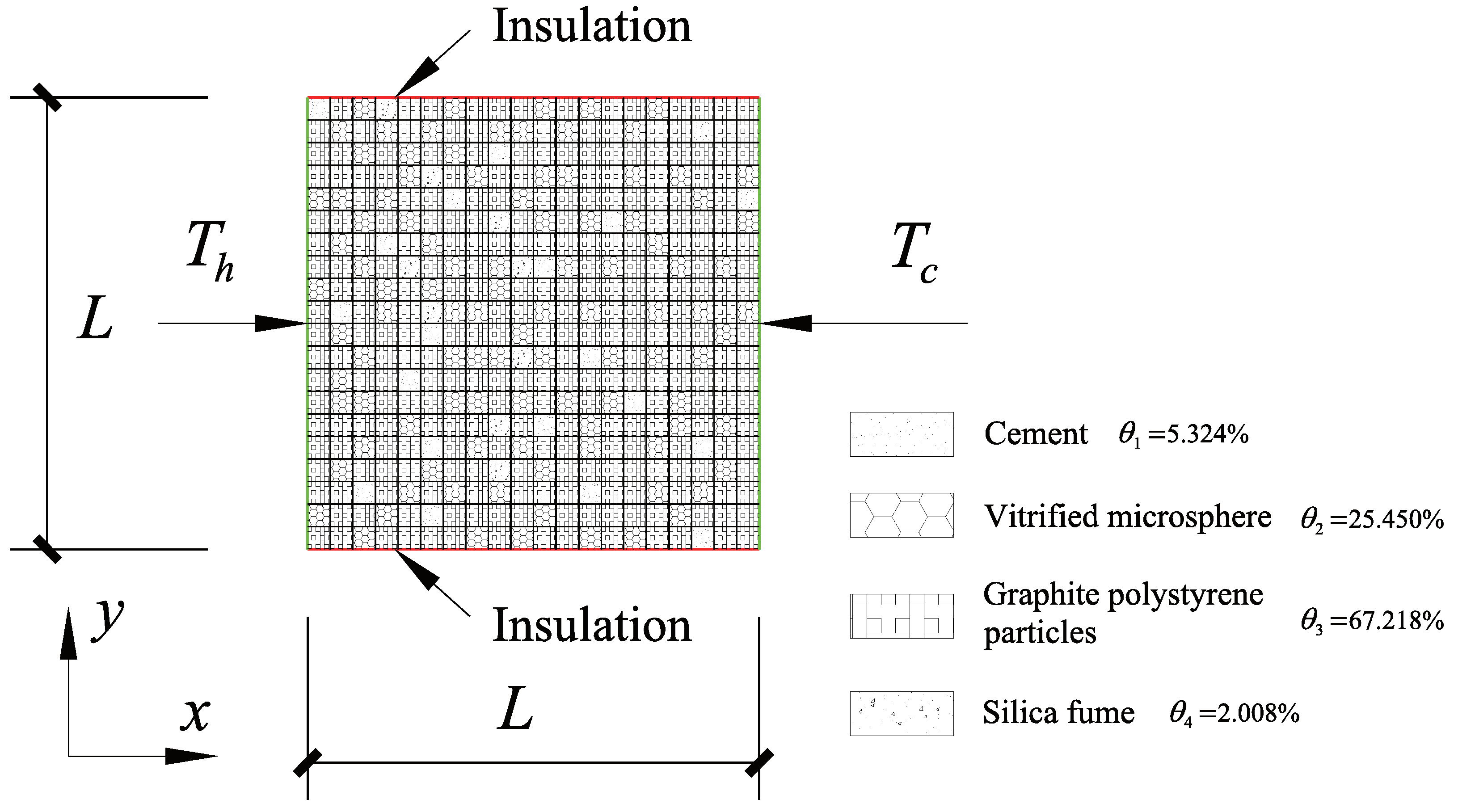
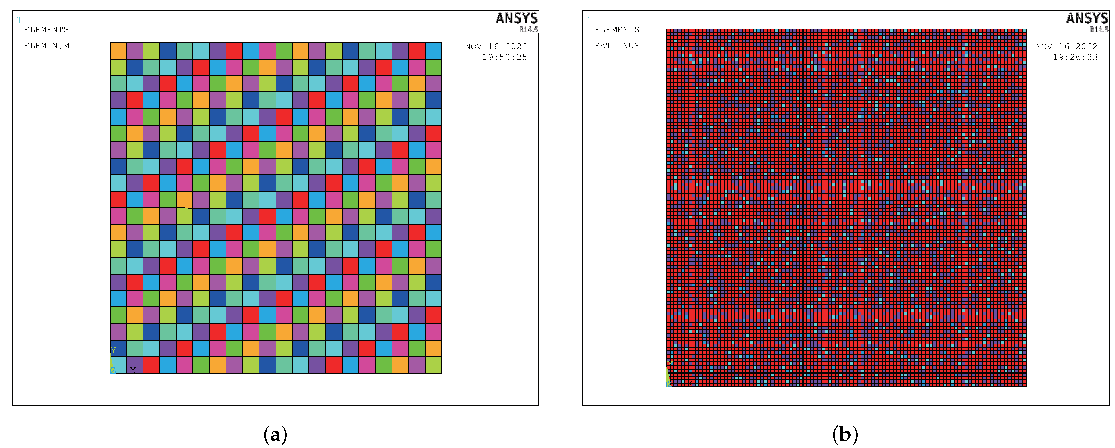
4. Numerical Simulation Analysis of Heat Conduction of the GCIB
4.1. Finite Element Model
- The GCIB is continuous inside, and the material is evenly distributed and dense, without cracks and gaps.
- The four materials inside the insulation board are closely bonded, and the materials are in a binding state during the analysis.
- The thermal conductivity of each constituent material is constant and independent of size and temperature [51].
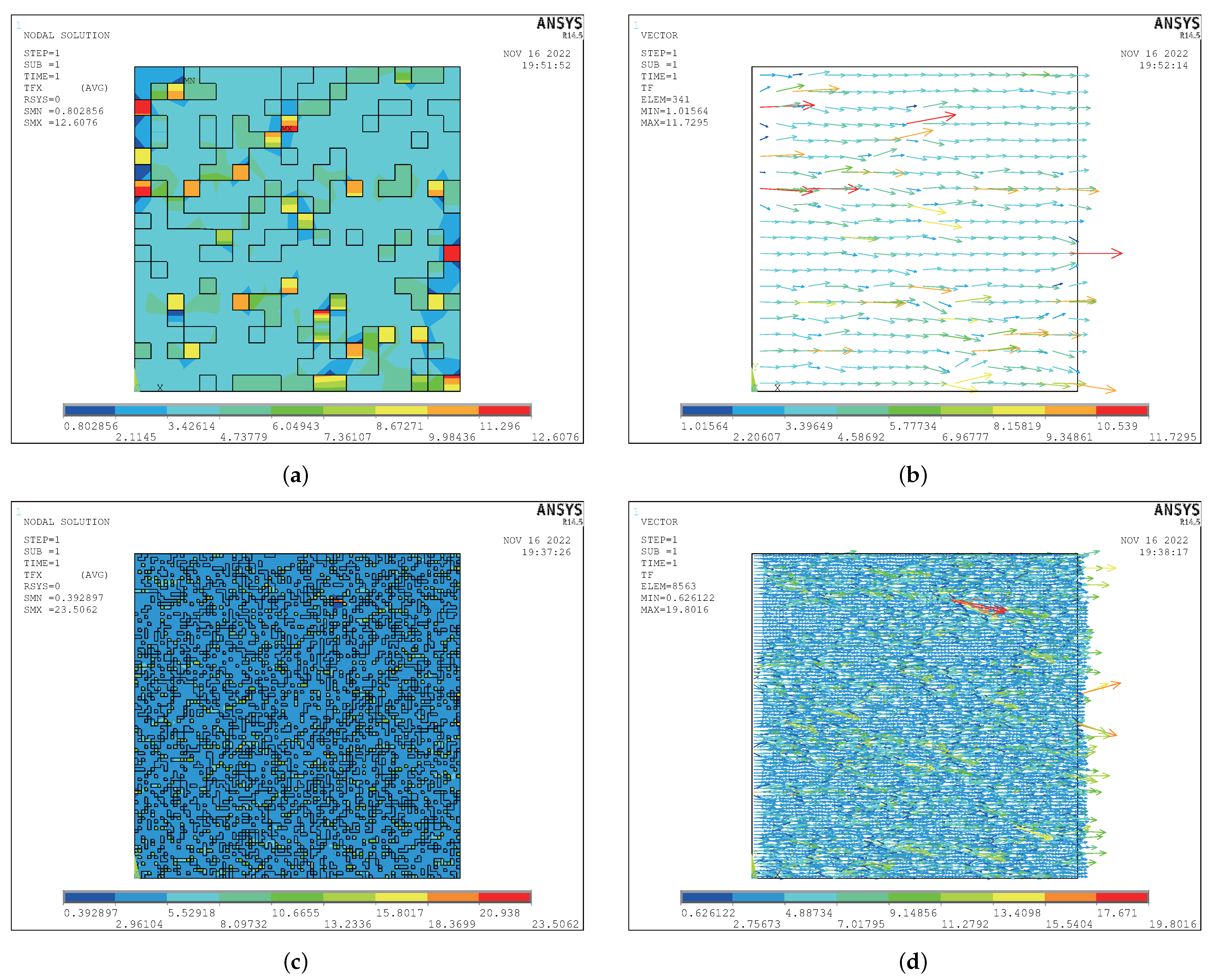
4.2. Numerical Simulation Results and Analysis
- (1)
- Thermal conductivity of the improved GCIB
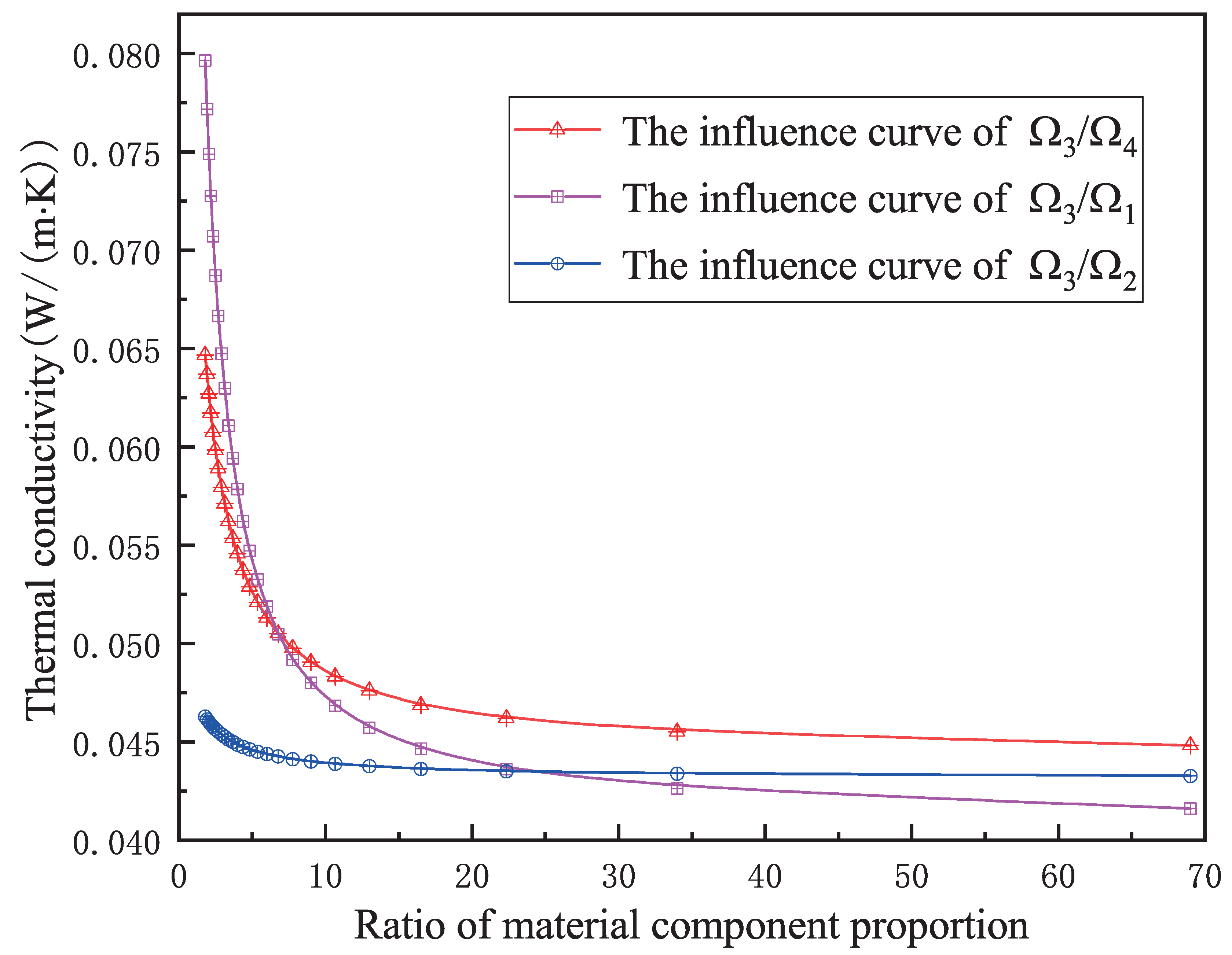
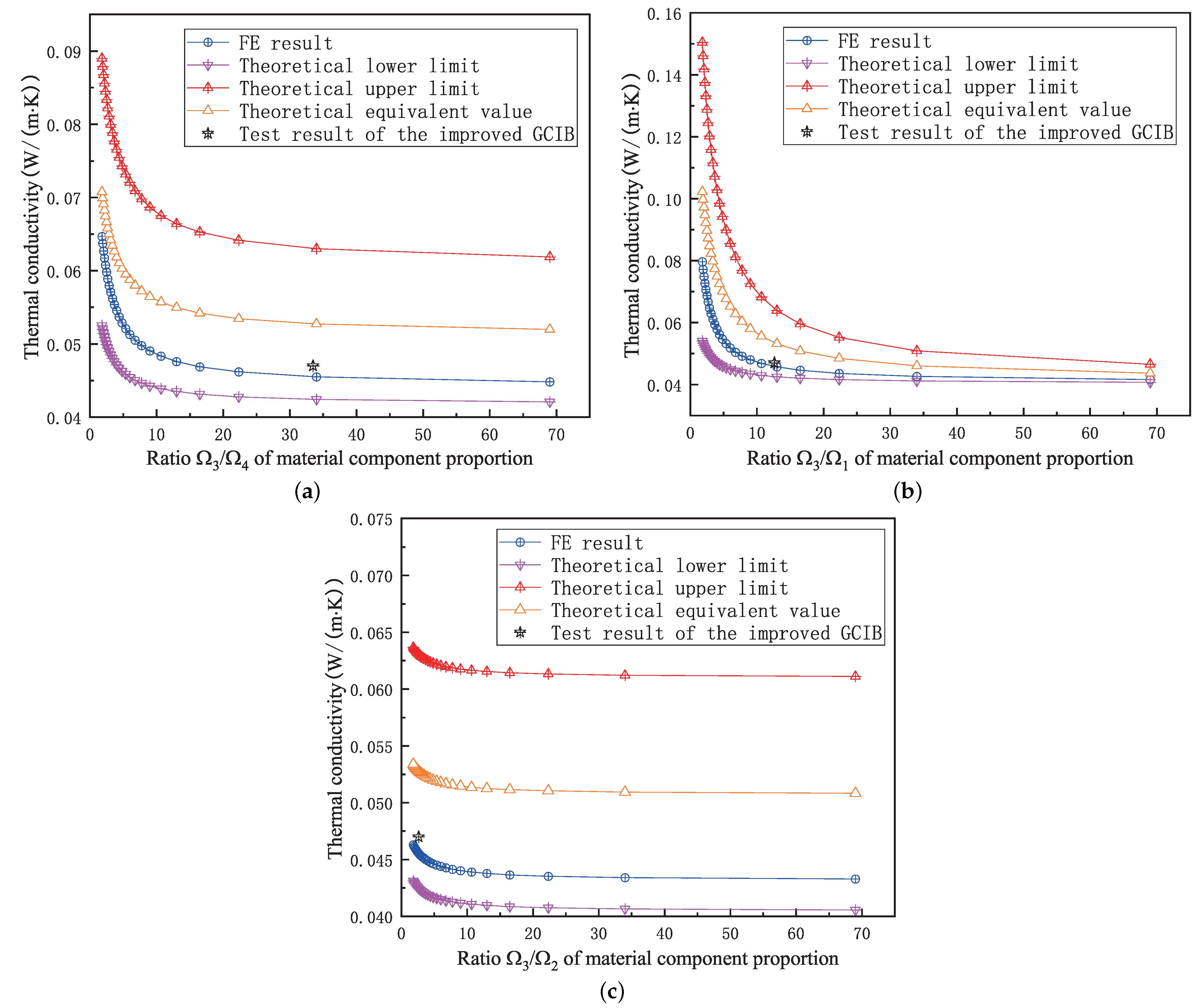
4.3. Influence of Material Component Ratios
5. Test Verification of Thermal Conductivity in the GCIB
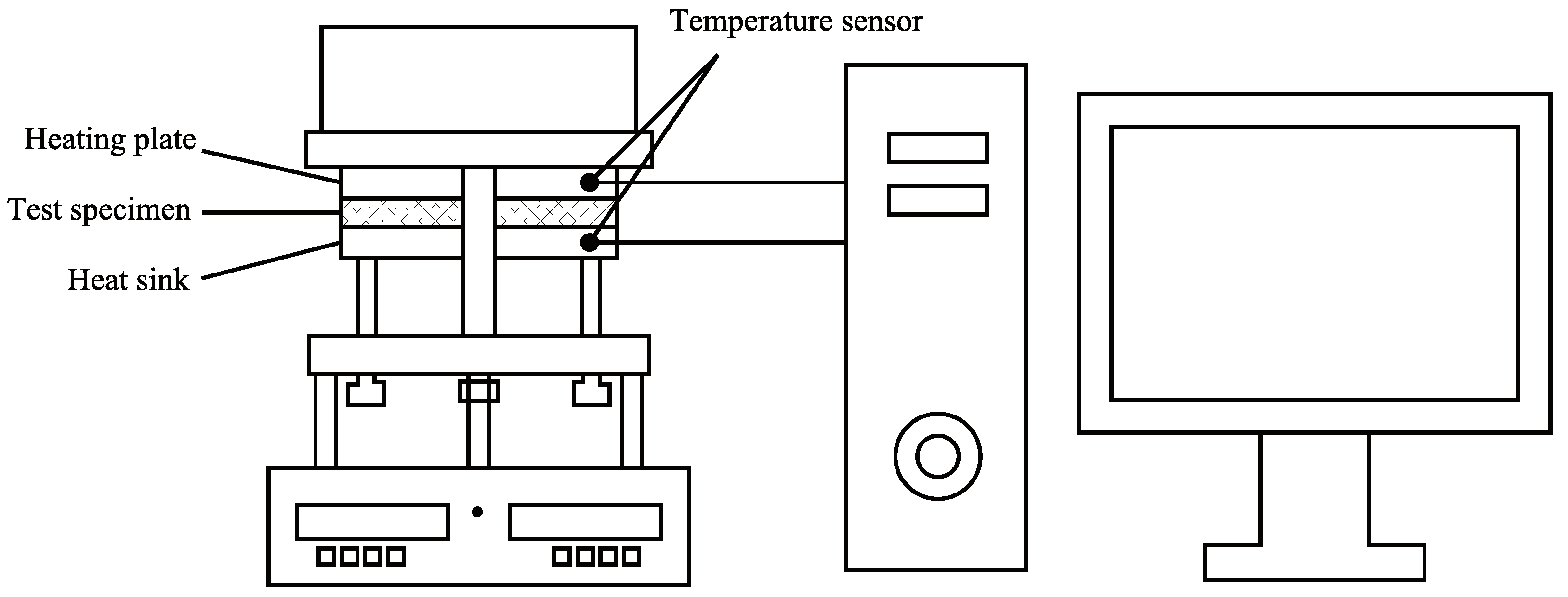
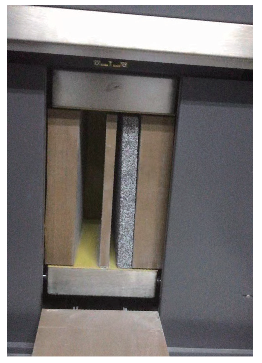
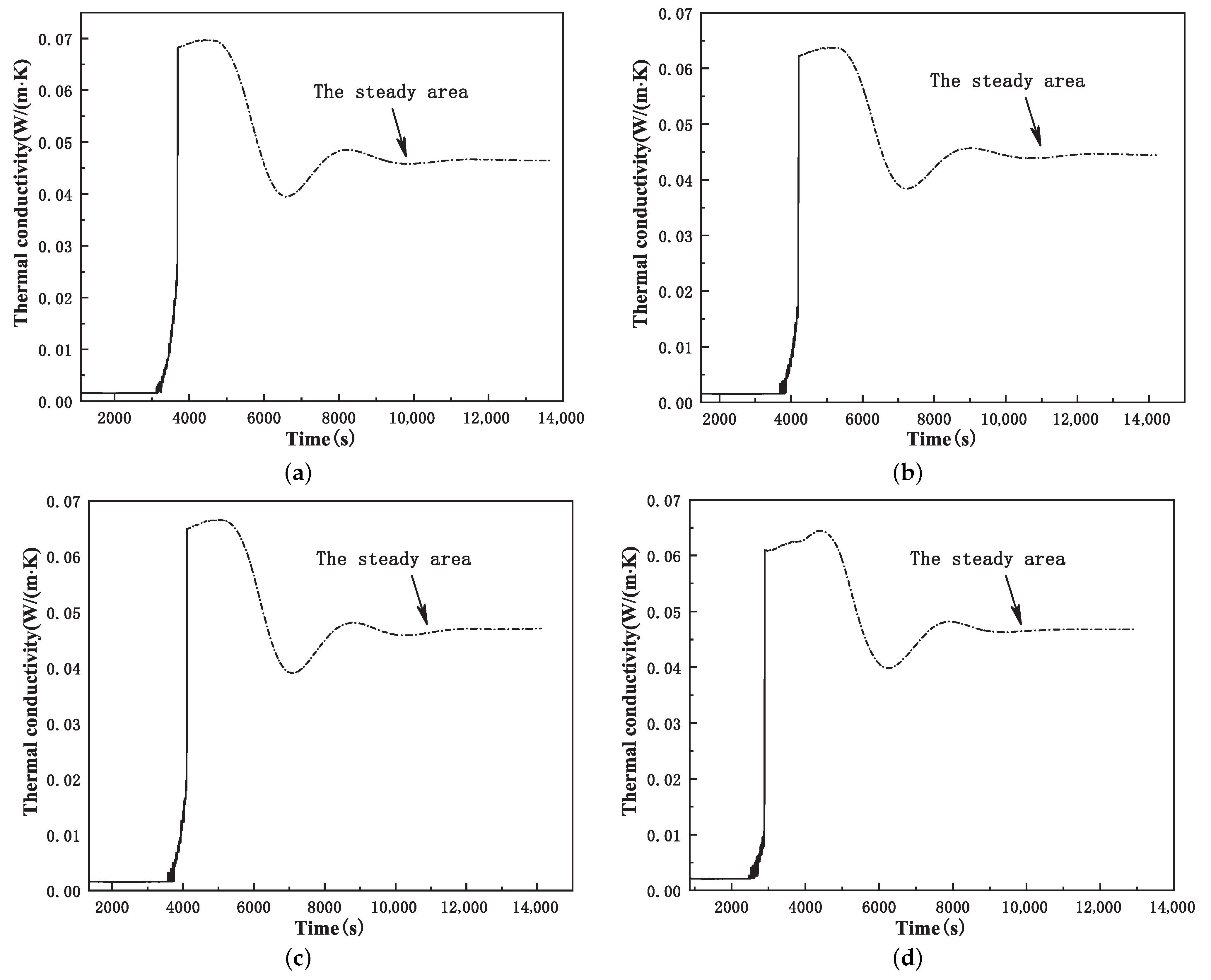
5.1. Measuring Equipment and Principle
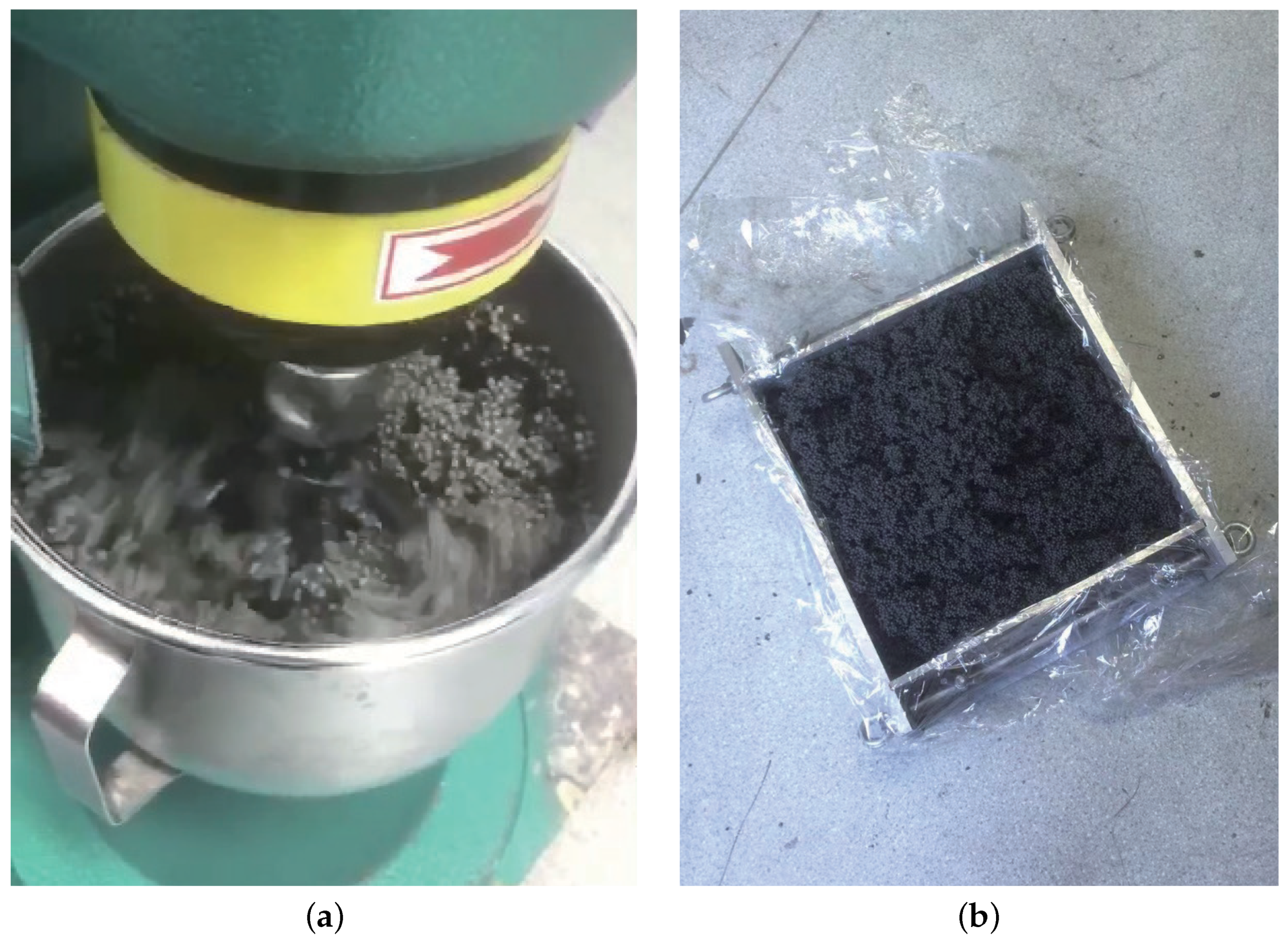
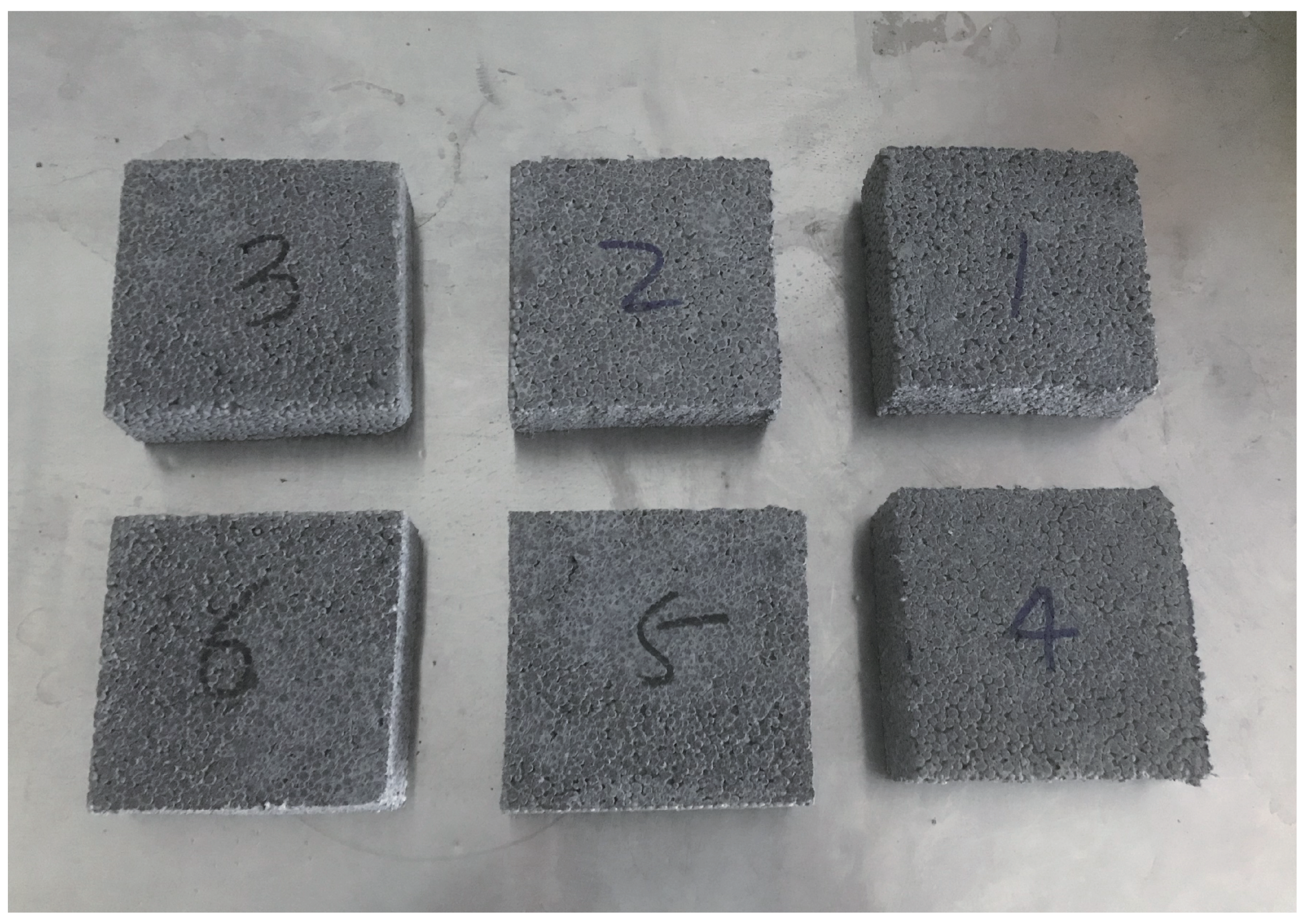
5.2. Test Sample Preparation and Test Process
5.3. Test Result
6. Results and Discussion
6.1. Comparison of Calculation Results of the GCIB
- (1)
- Theoretical calculation result
- (2)
- Comparison of results
6.2. Comparison of the Influence of Material Component Ratios
7. Conclusions
- The series and parallel models of the GCIB were proposed, which were used to calculate the thermal conductivity of the improved GCIB. The theoretical range of the thermal conductivity of the improved GCIB was obtained.
- According to the ratios of each material component in the improved composite insulation board, we established a numerical analysis model of the insulation board with a random distribution of each material component. Through analysis, we obtained the average heat flow density of the thermal conductivity calculation unit. According to the Fourier heat conduction calculation formula, we further obtained the thermal conductivity of the insulation board, which was within the reasonable range of theoretical calculation.
- Through numerical simulation, we studied the influence of the volume fraction of graphite polystyrene particles on the thermal conductivity of the GCIB. With the increase in the volume ratio of graphite polystyrene particles, the thermal conductivity of the GCIB decreased rapidly at the initial stage. When the volume ratio approached 10 (i.e., , , ), the thermal conductivity value tended to be stable.
- The thermal conductivity of the improved GCIB was obtained through the testing of the samples. The test results were within the range of the theoretical calculation results, and the numerical simulation results were in good agreement with the error within 0.5%.
Author Contributions
Funding
Data Availability Statement
Conflicts of Interest
References
- Pásztory, Z. An overview of factors influencing thermal conductivity of building insulation materials. J. Build. Eng. 2021, 44, 102604. [Google Scholar]
- Capuano, L. International Energy Outlook 2018 (IEO2018); US Energy Information Administration (EIA): Washington, DC, USA, 2018; p. 21.
- Domínguez-Muñoz, F.; Anderson, B.; Cejudo-López, J.M.; Carrillo-Andrés, A. Uncertainty in the thermal conductivity of insulation materials. Energy Build. 2010, 42, 2159–2168. [Google Scholar] [CrossRef]
- Chapter 31: Energy Estimating and Modeling Methods. In ASHRAE Handbook; American Society of Heating, Refrigerating, and Air-Conditioning Engineers: Atlanta, GA, USA, 2001.
- Peavy, B.A. A heat transfer note on temperature dependent thermal conductivity. J. Therm. Insul. Build. Envel. 1996, 20, 76–90. [Google Scholar] [CrossRef]
- Schiavoni, S.; Bianchi, F.; Asdrubali, F. Insulation materials for the building sector: A review and comparative analysis. Renew. Sustain. Energy Rev. 2016, 62, 988–1011. [Google Scholar] [CrossRef]
- Abu-Jdayil, B.; Mourad, A.H.; Hittini, W.; Hassan, M.; Hameedi, S. Traditional, state-of-the-art and renewable thermal building insulation materials: An overview. Constr. Build. Mater. 2019, 214, 709–735. [Google Scholar] [CrossRef]
- Yüksel, N. The review of some commonly used methods and techniques to measure the thermal conductivity of insulation materials. In Insulation Materials in Context of Sustainability; IntechOpen: London, UK, 2016. [Google Scholar]
- Lakatos, Á.; Kovács, Z. Comparison of thermal insulation performance of vacuum insulation panels with EPS protection layers measured with different methods. Energy Build. 2021, 236, 110771. [Google Scholar] [CrossRef]
- Berardi, U. The impact of aging and environmental conditions on the effective thermal conductivity of several foam materials. Energy 2019, 182, 777–794. [Google Scholar] [CrossRef]
- Kumar, D.; Alam, M.; Zou, P.X.; Sanjayan, J.G.; Memon, R.A. Comparative analysis of building insulation material properties and performance. Renew. Sustain. Energy Rev. 2020, 131, 110038. [Google Scholar] [CrossRef]
- Yang, J.; Wu, H.; Xu, X.; Huang, G.; Xu, T.; Guo, S.; Liang, Y. Numerical and experimental study on the thermal performance of aerogel insulating panels for building energy efficiency. Renew. Energy 2019, 138, 445–457. [Google Scholar] [CrossRef]
- König, J.; Nemanič, V.; Žumer, M.; Petersen, R.R.; Østergaard, M.B.; Yue, Y.; Suvorov, D. Evaluation of the contributions to the effective thermal conductivity of an open-porous-type foamed glass. Constr. Build. Mater. 2019, 214, 337–343. [Google Scholar] [CrossRef]
- Lamy-Mendes, A.; Pontinha, A.D.R.; Alves, P.; Santos, P.; Durães, L. Progress in silica aerogel-containing materials for buildings’ thermal insulation. Constr. Build. Mater. 2021, 286, 122815. [Google Scholar] [CrossRef]
- Li, X.; Peng, C.; Liu, L. Experimental study of the thermal performance of a building wall with vacuum insulation panels and extruded polystyrene foams. Appl. Therm. Eng. 2020, 80, 115801. [Google Scholar] [CrossRef]
- Wang, Y.; Zhang, S.; Wang, D.; Liu, Y. Experimental study on the influence of temperature and humidity on the thermal conductivity of building insulation materials. Energy Built Environ. 2022, in press. [Google Scholar] [CrossRef]
- Pfundstein, M.; Gellert, R.; Spitzner, M.; Rudolphi, A. Insulating Materials: Principles, Materials, Applications; Walter de Gruyter: Berlin, Germany, 2012. [Google Scholar]
- Zhang, H. Building Materials in Civil Engineering; Elsevier: Amsterdam, The Netherlands, 2011. [Google Scholar]
- Omer, S.A.; Riffat, S.B.; Qiu, G. Thermal insulations for hot water cylinders: A review and a conceptual evaluation. Build. Serv. Eng. Res. Technol. 2007, 28, 275–293. [Google Scholar] [CrossRef]
- Petrosyan, A.L. The Influence of the Properties of Thermal-Insulation Materials on the Thermomoist Indicators of a Building. Key Eng. Mater. 2022, 906, 125–133. [Google Scholar] [CrossRef]
- Khoukhi, M. The combined effect of heat and moisture transfer dependent thermal conductivity of polystyrene insulation material: Impact on building energy performance. Energy Build. 2018, 169, 228–235. [Google Scholar] [CrossRef]
- Berardi, U.; Nosrati, R.H. Long-term thermal conductivity of aerogel-enhanced insulating materials under different laboratory aging conditions. Energy 2018, 147, 1188–1202. [Google Scholar] [CrossRef]
- Berardi, U.; Tronchin, L.; Manfren, M.; Nastasi, B. On the effects of variation of thermal conductivity in buildings in the Italian construction sector. Energies 2018, 11, 872. [Google Scholar] [CrossRef]
- Al-Homoud, M.S. Performance characteristics and practical applications of common building thermal insulation materials. Build. Environ. 2005, 40, 353–366. [Google Scholar] [CrossRef]
- Berardi, U.; Naldi, M. The impact of the temperature dependent thermal conductivity of insulating materials on the effective building envelope performance. Energy Build. 2017, 144, 262–275. [Google Scholar] [CrossRef]
- Wu, J.W.; Sung, W.F.; Chu, H.S. Thermal conductivity of polyurethane foams. Int. J. Heat Mass Transf. 1999, 42, 2211–2217. [Google Scholar] [CrossRef]
- Hoseini, A.; McCague, C.; Andisheh-Tadbir, M.; Bahrami, M. Aerogel blankets: From mathematical modeling to material characterization and experimental analysis. Int. J. Heat Mass Transf. 2016, 93, 1124–1131. [Google Scholar] [CrossRef]
- Majumder, A.; Canale, L.; Mastino, C.C.; Pacitto, A.; Frattolillo, A.; Dell’Isola, M. Thermal characterization of recycled materials for building insulation. Energies 2021, 14, 3564. [Google Scholar] [CrossRef]
- Hossain, M.D.; Hassan, M.K.; Akl, M.; Pathirana, S.; Rahnamayiezekavat, P.; Douglas, G.; Bhat, T.; Saha, S. Fire Behaviour of Insulation Panels Commonly Used in High-Rise Buildings. Fire 2022, 5, 81. [Google Scholar] [CrossRef]
- Zhang, J.; Cao, Y.; Wang, X. Study on Properties of Graphite Polystyrene Permeable Composite Insulation Board. IOP Conf. Ser. Mater. Sci. Eng. 2020, 744, 012043. [Google Scholar] [CrossRef]
- Li, B.; Huo, Y.; Yin, S. Sustainable financing efficiency and environmental value in China’s energy conservation and environmental protection industry under the double carbon target. Sustainability 2022, 14, 9604. [Google Scholar] [CrossRef]
- Huang, X.; Lu, X.; Sun, Y.; Yao, J.; Zhu, W. A Comprehensive Performance Evaluation of Chinese Energy Supply Chain under “Double-Carbon” Goals Based on AHP and Three-Stage DEA. Sustainability 2022, 14, 10149. [Google Scholar] [CrossRef]
- Moayedi, H.; Mosavi, A. Double-target based neural networks in predicting energy consumption in residential buildings. Energies 2021, 14, 1331. [Google Scholar] [CrossRef]
- GB/T 17431.2-2010; Lightweight Aggregates and Its Test Methods—Part 2: Test Methods for Lightweight Aggregates. Standardization Administration of China: Beijing, China, 2010.
- ISO8302:1991; Thermal Insulation—Determination of Steady-State Thermal Resistance and Related Properties—Guarded Hot Plate Apparatus. ISO: Geneva, Switzerland, 1991.
- Bentz, D.P. A review of early-age properties of cement-based materials. Cem. Concr. Res. 2008, 38, 196–204. [Google Scholar] [CrossRef]
- Zhou, C. Research on the Preparation and Engineering Properties of High Performance Glass Hollow Bead Thermal Insulation Mortar. East China University of Technology: Fuzhou, China, 2022. [Google Scholar]
- Gong, J.; Duan, Z.; Sun, K.; Xiao, M. Waterproof properties of thermal insulation mortar containing vitrified microsphere. Constr. Build. Mater. 2016, 123, 274–280. [Google Scholar] [CrossRef]
- Lakatos, Á.; Deák, I.; Berardi, U. Thermal characterization of different graphite polystyrene. Int. Rev. Appl. Sci. Eng. 2018, 9, 163–168. [Google Scholar] [CrossRef]
- Khan, M.I.; Siddique, R. Utilization of silica fume in concrete: Review of durability properties. Resour. Conserv. Recycl. 2011, 57, 30–35. [Google Scholar] [CrossRef]
- Song, K.; Mukhopadhyaya, P. Vacuum insulation panels (VIPS) in building envelope constructions: An overview. Int. Rev. Appl. Sci. Eng. 2016, 7, 113–119. [Google Scholar] [CrossRef]
- Simpson, A.; Rattigan, I.G.; Kalavsky, E.; Parr, G. Thermal conductivity and conditioning of grey expanded polystyrene foams. Cell. Polym. 2020, 39, 238–262. [Google Scholar] [CrossRef]
- Wei, G.; Liu, Y.; Zhang, X.; Yu, F.; Du, X. Thermal conductivities study on silica aerogel and its composite insulation materials. Int. J. Heat Mass Transf. 2011, 54, 2355–2366. [Google Scholar] [CrossRef]
- Xie, T.; He, Y.L.; Li, Y.S.; Tao, W.Q. Theoretical and Numerical Study on Thermal Properties of Fibrous Insulation Materials. In Proceedings of the 14th Minsk International Forum on Heat and Mass Transfer, Minsk, Belarus, 10–13 September 2012. [Google Scholar]
- Karamanos, A.; Papadopoulos, A.M.; Anastasellos, D. Heat transfer phenomena in fibrous insulating materials. In Proceedings of the 2004 WSEAS/IASME International Conference on Heat and Mass, Corfu, Greece, 16–19 August 2004. [Google Scholar]
- Karamanos, A.; Hadiarakou, S.; Papadopoulos, A.M. The impact of temperature and moisture on the thermal performance of stone wool. Energy Build. 2008, 40, 1402–1411. [Google Scholar] [CrossRef]
- Csanády, D.; Fenyvesi, O.; Nagy, B. Heat transfer in straw-based thermal insulating materials. Materials 2021, 14, 4408. [Google Scholar] [CrossRef] [PubMed]
- Narasimhan, T.N. Fourier’s heat conduction equation: History, influence, and connections. Rev. Geophys. 1999, 37, 151–172. [Google Scholar] [CrossRef]
- Greiner, W.; Neise, L.; Stöcker, H. Thermodynamics and Statistical Mechanics; Springer Science & Business Media: Berlin/Heidelberg, Germany, 2012. [Google Scholar]
- Stowe, K. An Introduction to Thermodynamics and Statistical Mechanics; Cambridge University Press: Cambridge, UK, 2007. [Google Scholar]
- Zhang, Y.F.; Zhao, Y.H.; Bai, S.L.; Yuan, X. Numerical simulation of thermal conductivity of graphene filled polymer composites. Compos. Part B Eng. 2016, 106, 324–331. [Google Scholar] [CrossRef]
- Liu, H.; Tian, Y.; Jiao, J.; Wu, X.; Li, Z. Thermal conductivity modeling of hollow fiber-based porous structures for thermal insulation applications. J. -Non-Cryst. Solids 2022, 575, 121188. [Google Scholar] [CrossRef]
- Hiroshi, H.; Minoru, T. Equivalent inclusion method for steady state heat conduction in composites. Int. J. Eng. Sci.. 1986, 24, 1159–1172. [Google Scholar] [CrossRef]
- Sanchez-Calderon, I.; Merillas, B.; Bernardo, V.; Rodríguez-Pérez, M.Á. Methodology for measuring the thermal conductivity of insulating samples with small dimensions by heat flow meter technique. J. Therm. Anal. Calorim. 2022, 147, 12523–12533. [Google Scholar] [CrossRef]
- Baldinelli, G.; Bianchi, F.; Gendelis, S.; Jakovics, A.; Morini, G.L.; Falcioni, S.; Fantucci, S.; Serra, V.; Navacerrada, M.; Díaz, C.; et al. Thermal conductivity measurement of insulating innovative building materials by hot plate and heat flow meter devices: A Round Robin Test. Int. J. Therm. Sci. 2019, 139, 25–35. [Google Scholar] [CrossRef]
- Wang, Y.; Liu, K.; Liu, Y.; Wang, D.; Liu, J. The impact of temperature and relative humidity dependent thermal conductivity of insulation materials on heat transfer through the building envelope. J. Build. Eng. 2022, 46, 103700. [Google Scholar] [CrossRef]
- JG/T 536-2017; Thermosetting Composite Polystyrene Foam Insulation Board. Ministry of Housing and Urban-Rural Development of the People’s Republic of China: Beijing, China, 2017.
- Xie, Y.; Dang, Y.; Wang, Z. College Physics Experiment; Higher Education Press: Beijing, China, 2017. [Google Scholar]


| Components | Density () | Mass Percentage (%) | Thermal Conductivity ()) |
|---|---|---|---|
| Cement | 1135 | 63.2 | 0.453 |
| Vitrified microspheres | 68 | 18.1 | 0.046 |
| Graphite polystyrene particles | 16.5 | 11.6 | 0.038 |
| Silica fume | 338 | 7.1 | 0.151 |
| Components | SiO | CaO | AlO | FeO | MgO | SO | KO | NaO | TiO | Other Surplus |
|---|---|---|---|---|---|---|---|---|---|---|
| Proportion (%) | 22.9 | 56.8 | 7.3 | 2.7 | 2.7 | 2.3 | 0.6 | 0.3 | 0.3 | 4.1 |
| Insulation Board No. | Average | Standard Deviation | ||||||
|---|---|---|---|---|---|---|---|---|
| Thermal conductivity (W/(m·K)) | 0.047 | 0.044 | 0.047 | 0.047 | 0.050 | 0.044 | 0.047 | 0.002 |
Disclaimer/Publisher’s Note: The statements, opinions and data contained in all publications are solely those of the individual author(s) and contributor(s) and not of MDPI and/or the editor(s). MDPI and/or the editor(s) disclaim responsibility for any injury to people or property resulting from any ideas, methods, instructions or products referred to in the content. |
© 2023 by the authors. Licensee MDPI, Basel, Switzerland. This article is an open access article distributed under the terms and conditions of the Creative Commons Attribution (CC BY) license (https://creativecommons.org/licenses/by/4.0/).
Share and Cite
Liu, G.; Guo, Y.; Jian, Z.; Huang, M.; Zhao, T. Experimental Study on the Thermal Conductivity of Improved Graphite Composite Insulation Boards. Crystals 2023, 13, 102. https://doi.org/10.3390/cryst13010102
Liu G, Guo Y, Jian Z, Huang M, Zhao T. Experimental Study on the Thermal Conductivity of Improved Graphite Composite Insulation Boards. Crystals. 2023; 13(1):102. https://doi.org/10.3390/cryst13010102
Chicago/Turabian StyleLiu, Genbao, Yutao Guo, Zhiyu Jian, Mojia Huang, and Tengfei Zhao. 2023. "Experimental Study on the Thermal Conductivity of Improved Graphite Composite Insulation Boards" Crystals 13, no. 1: 102. https://doi.org/10.3390/cryst13010102
APA StyleLiu, G., Guo, Y., Jian, Z., Huang, M., & Zhao, T. (2023). Experimental Study on the Thermal Conductivity of Improved Graphite Composite Insulation Boards. Crystals, 13(1), 102. https://doi.org/10.3390/cryst13010102