Article

Improving the Directionality of Low-Frequency Acoustic Radiation by a Finite Array of Quadrupolar Sources with Acoustic Metamaterials

1
Key Laboratory of Modern Acoustics, Institute of Acoustics and School of Physics, Collaborative Innovation Center of Advanced Microstructures, Nanjing University, Nanjing 210093, China
2
State Key Laboratory of Acoustics, Institute of Acoustics, Chinese Academy of Sciences, Beijing 100190, China
*
Authors to whom correspondence should be addressed.
Crystals 2023, 13(1), 101; https://doi.org/10.3390/cryst13010101
Submission received: 25 November 2022 / Revised: 24 December 2022 / Accepted: 29 December 2022 / Published: 5 January 2023
(This article belongs to the Special Issue Active, Tunable and Reconfigurable Elastic Metamaterials)

Abstract

:
Manipulating radiation patterns is challenging, especially at low frequencies. In this paper, we demonstrate that acoustic metamaterials arranged as an array of quadrupoles remarkably improve the directionality of acoustic radiation at low frequencies, compared with previous metamaterials arranged as monopole and dipole structures. The directivity of the acoustic radiation can be adjusted by changing the characteristic parameter and the symmetry of the structure, which provides a flexible method of adjusting radiation directions. The directionality can be further improved by constructing a linear array. Our work establishes acoustic radiation control via quadrupolar metamaterials.

1. Introduction

An increasing number of researchers are attempting to improve the directivity of wave propagation. Early studies focused on the effect of periodicity on spatial dispersion to modulate radiation patterns, which counteracts wave spreading via crystal anisotropy [1,2,3] and band-edge states [4,5,6]. Recently, transformation optics (acoustics) has been used to modulate waves in cylindrical coordinates, where an omnidirectional line radiation source is modulated to specified patterns and directions [7]. Work has also been done on phonon crystals and topological acoustics [8,9]. Song et al. devised a class of anisotropic metamaterials that enhance directional acoustic emission [10]. Jun also designed enhanced directional emission (EDE) based on an anisotropic metamaterial [11]. However, these designs rely on bulk materials or structures that provide multiple reflections; thus, they are usually bulky, lossy, and difficult to fabricate at low frequency. To solve this problem, Tong et al. proposed and demonstrated acoustically enhanced directional radiation with topological interface states in a specially designed acoustic waveguide with a subwavelength width and no additional structure for multiple reflections [12]. However, this design cannot achieve intense radiation without sidelobes. In addition to adjusting the material properties, Quan et al. proposed an effective way to modulate radiation patterns by adjusting the surface impedance [13]. They designed a kind of metamaterial using Fabry–Perot resonance [14] and the resonance of two-dimensional Helmholtz resonators (HRs). When the incident acoustic wave frequency is near the resonance frequency of an HR, the impedance interface is converted to a soft boundary. This structure is equivalent to a quasi-dipole source [13]. Ciaburro Giuseppe achieved good sound absorption by combining the advantages of membrane resonance absorption and cavity resonance [15]. Furthermore, a linear array of point sources can be used to generate acoustic transmission with high directivity. A Yagi–Uda nano antenna array has been designed to improve and redirect the radiation of oscillating point dipoles in the electromagnetic domain [16]. Ding used a dipole array to enhance the directionality of sound waves by adjusting the distance between structural units [17].
To achieve better directionality and ensure that the component size is not too large, we propose a new structure to obtain a radiation pattern using a quadrupole unit with high directivity without any sidelobe in a broad frequency band, and verify it through numerical simulations and experiments. This structure is based on the work of Quan et al. [13]. Different radiation properties are obtained by adjusting the acoustic parameter, and the properties of this structure are completely determined by the structure itself instead of the material. Our results show that this structure strongly controls the sound field, realizing functions that natural materials cannot complete. This provides a new approach to controlling acoustic radiation using quadrupolar metamaterials.
In the second section, the quadrupole structure is introduced, and a simulation and experiment are carried out to verify the theoretical analysis. In the third section, a structure is proposed that can be used to adjust the radiation direction, and the theory is verified by simulations. The fourth section proposes a structure with a linear quadrupole array to produce strong directional radiation, and the theoretical results are verified by simulations and experiments. In the fifth section, the summary and prospects are given.

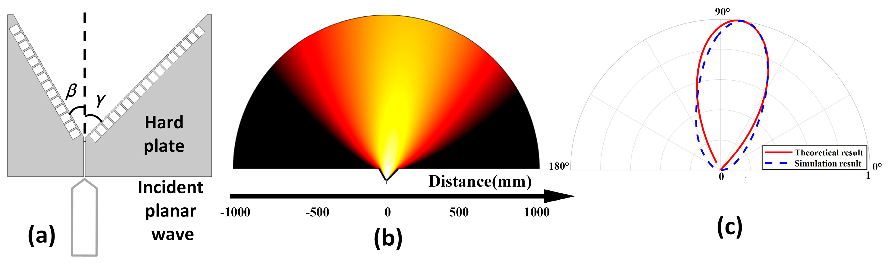
2. Theoretical Derivation and Verification

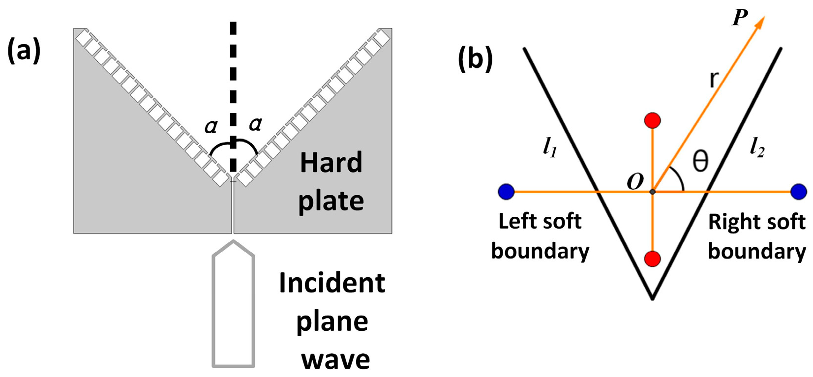
2.1. Theoretical Analysis

A quadrupole has better ability to control radiation direction than a dipole, and the structure designed by Quan et al. provides a way to obtain the equivalent dipole radiation [13]. On this basis, we propose the structure for equivalent quadrupole radiation shown in Figure 1a. This structure controls the radiation pattern using the boundary rather than the entire propagation region, which greatly reduces the complexity of pattern control and expands the application of wave modulation. Our system is similar to that of a single slit surrounded by finite, periodically perforated grooves. The horn has an opening angle of 2 α . The two surfaces of the structure are etched with a certain number of HRs. This method has a wider working broadband [9] than the directional beam setup of Zhou et al. [18].
When | Z s / ρ 0 c 0 | 0 or | Z s / ρ 0 c 0 | , the boundary can effectively function as a soft or rigid boundary, respectively. Therefore, a surface etched with HRs can function effectively as a soft boundary when an HR resonates. Using Fabry–Perot resonance theory [8], we design a slit with an appropriate length that guarantees high radiation efficiency. In this case, the radiation may be regarded as an effective quadrupolar source under the mirror principle, which is shown in Figure 1b. Each red point represents a point sound source of positive phase, and each blue point represents a point sound source of negative phase induced by the soft boundaries; l 1 and l 2 are the structural interfaces. By changing α , we can distribute the four effective point sound sources at the four vertices of the rhombic shape.
The velocity potential at a point P in the far field due to a point sound source can be written as
Φ P = i = 1 4 Φ i = i = 1 4 ( 1 ) i + 1 A r i e j ( ω t k r i ) .
The positive and negative sound sources are symmetric about the structural boundary. According to the above relation and the far-field approximation,
r 1 = r + d sin θ , r 3 = r d sin θ , r 2 = r + d tan α sin θ , r 4 = r d tan α sin θ ,   1 r i 1 r , ( i = 1 , 2 , 3 , 4 ) .  
The velocity potential at the point P is
Φ P = 2 A r e j ( ω t k r ) [ cos ( k d sin θ ) cos ( k d tan α cos θ ) ] .
Because k d < < 1 , this can be written as
Φ P = k 2 d 2 A 2 r sin 2 α e j ( ω t k r ) cos ( θ α ) cos ( θ + α ) .
Here, the theoretical directivity of the structure, D P ( θ ) , is
D P ( θ ) = | cos ( θ α ) cos ( θ + α ) | .
The radiation is limited by the boundaries at both ends of the structure, thus θ is limited to [ π 2 α , π 2 + α ] .

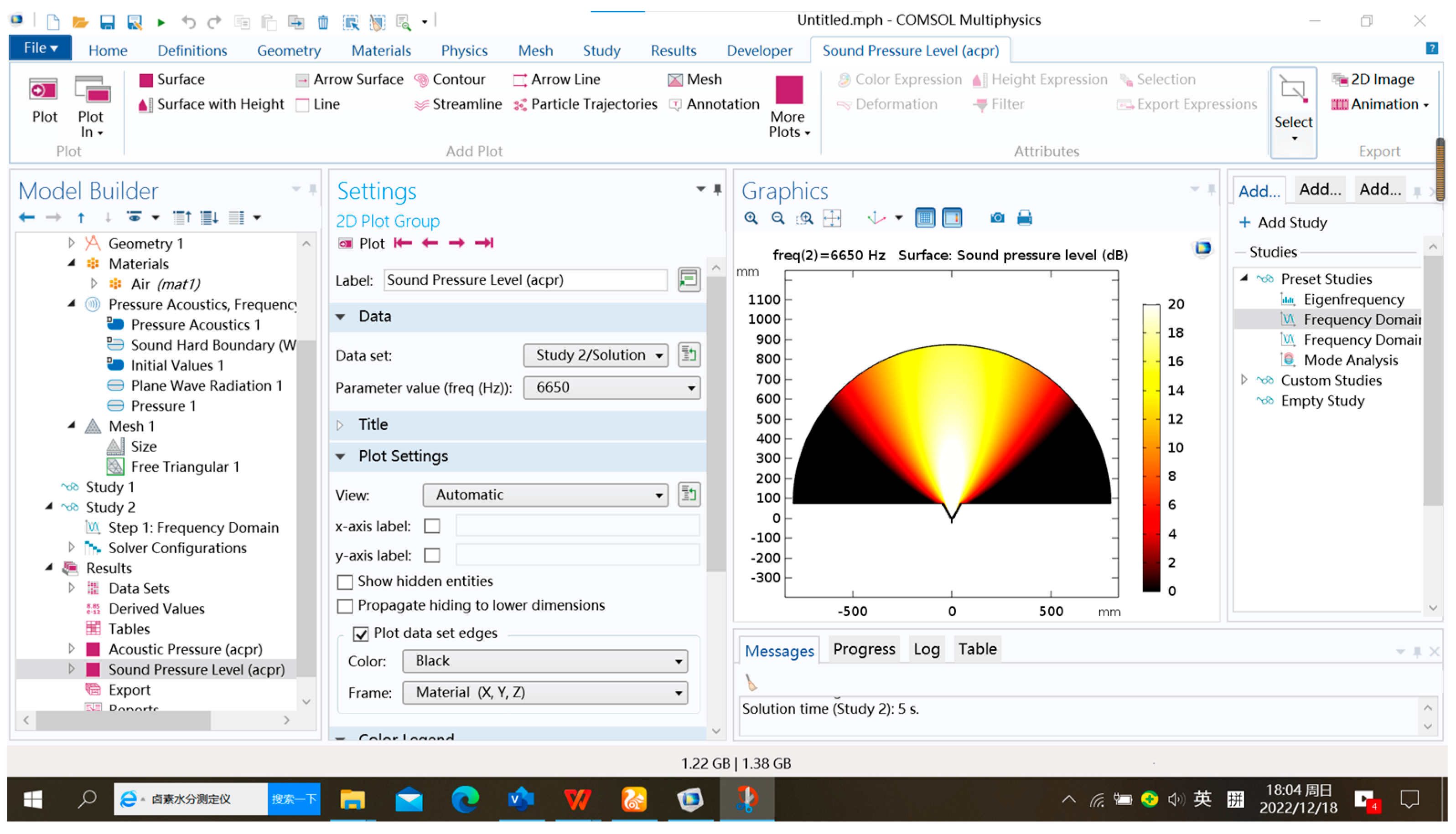
2.2. Numerical Simulation

To validate the theory, the directivity diagram and sound pressure diagram were simulated using COMSOL Multiphysics® 5.5 for | Z s / ρ 0 c 0 | 0 , α = 30 ° , α = 45 ° , and α = 60 ° , as shown in Figure 2a–f. Acoustic modules were simulated in two dimensions for a slit width of 2 mm and slit length of 25 mm in each structure. Each structure covered 28 periodical HRs, with each side containing 14 HRs. The cavity size was 5 mm × 6 mm, the neck size was 1 mm × 1 mm, and sound waves with a frequency of 6650 Hz were incident from the slit into the free space ahead. Each structure was made of resin material, and the rest of the space consisted of air. All boundaries in contact with the material were set as hard boundaries, and the rest were set to plane wave radiation. The simulation page is provided in Figure A1.
The directivity maps based on Equation (5) are plotted in Figure 2a–c. The simulation result for the structure with only one slit is also drawn in Figure 2a.

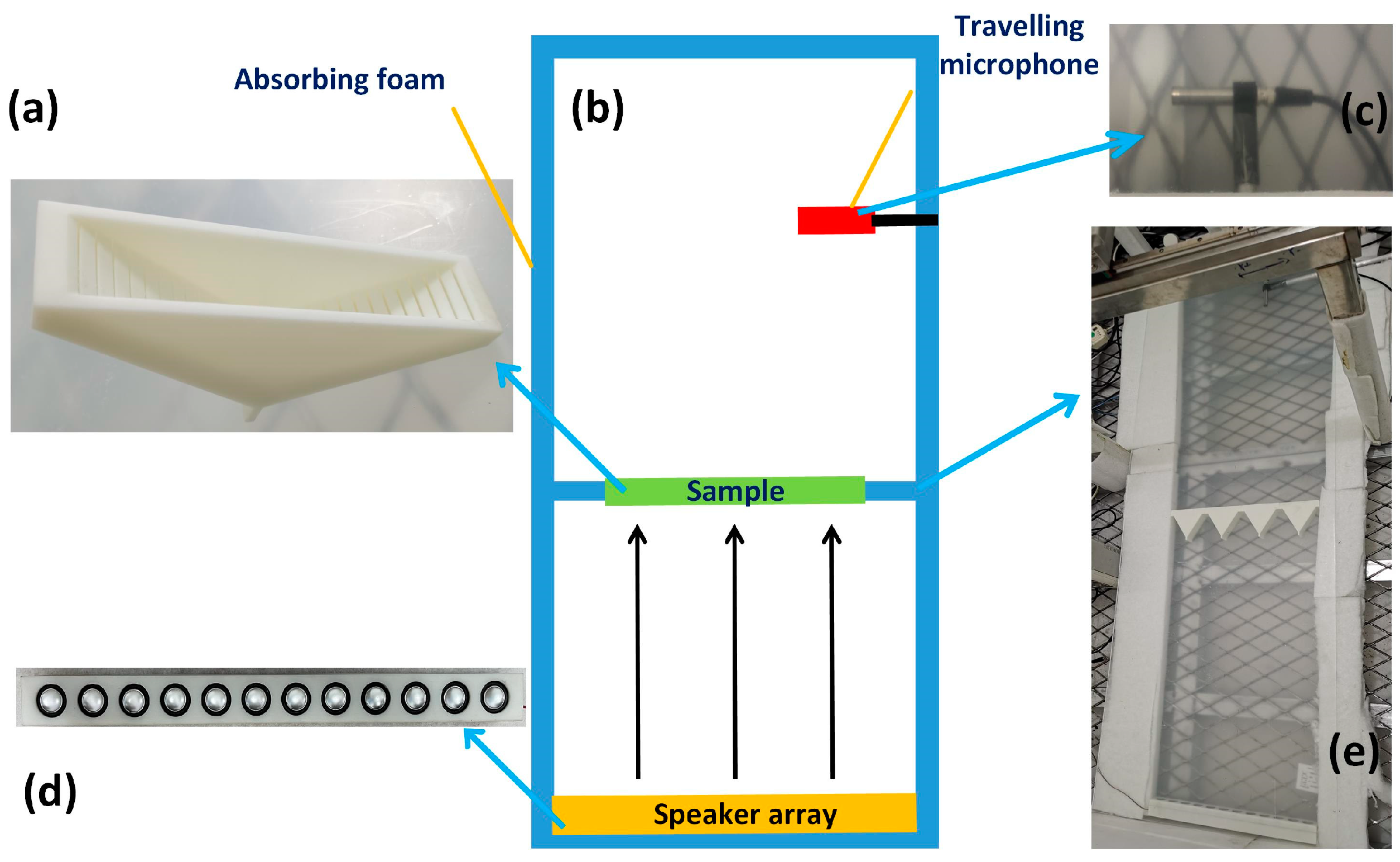
2.3. Experimental Results

The theory was further verified through experiments. As shown in Figure 3a, the element was stretched by the two-dimensional resin structure. The unit thickness was 2.7 cm, both sides were sealed with a 4 mm-thick resin plate, and the total thickness of each element was 35 mm. The width of the central slit was 2 mm, and the elements had α values of 30°, 45°, and 60°. Detailed data for these structures are presented in Table 1. The experiment was carried out in an anechoic chamber to eliminate the influence of reflected waves. The full range of the intensity pattern was mapped within an acoustic plane wave normally incident on the unit. When the relative effective boundary impedance is | Z s / ρ 0 c 0 | 0 , the frequency of the acoustic incident plane wave is approximately 6650 Hz.
The experimental system diagram is shown in Figure 3b,e. The experimental device was placed between two wave guide plates, and the space around it was filled with sound-absorbing cotton. The plane wave was generated by a speaker array [Figure 3d], and the sample was placed in the front [Figure 3a]. The speaker array in this experiment was custom-made, each unit could make sounds in the range 20–20,000 Hz, and there were 12 units in total. The travelling microphone [Figure 3c] was driven by a stepping motor to collect the sound signal in front of the sample. The stepping motor C-scanned an area of 40 cm × 38 cm, and each step was 2 cm with a precision of 1 mm. The instrumental parameters are provided in Tabel A2. During the experiment, the travelling microphone collected the average sound pressure at the nearest front end in real time, and the data were recorded by the computer. The sound pressure maps are plotted in Figure 2g–i. The experimental normalized directivity maps are drawn in Figure 2a–c to better compare the experimental and theoretical results.

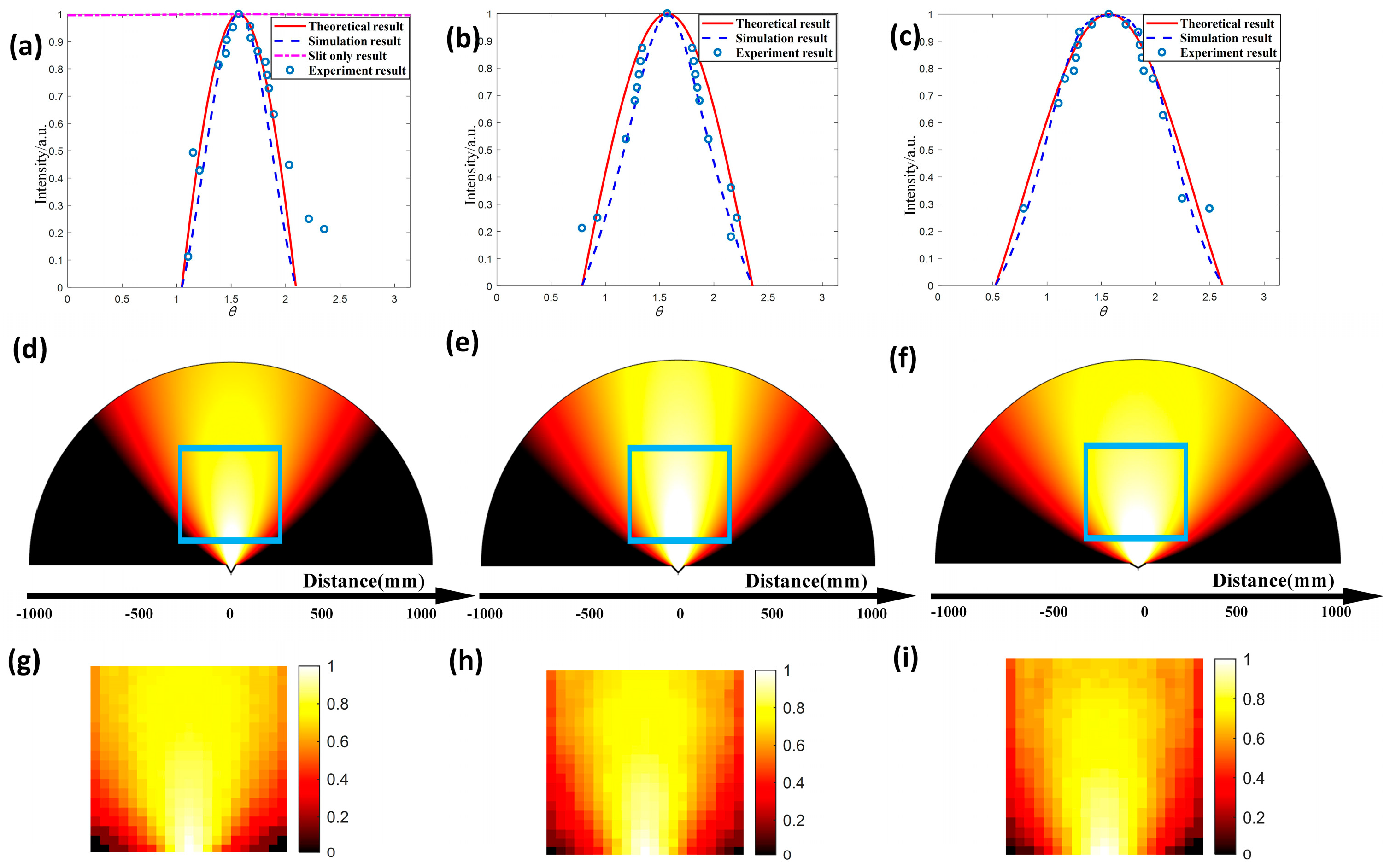
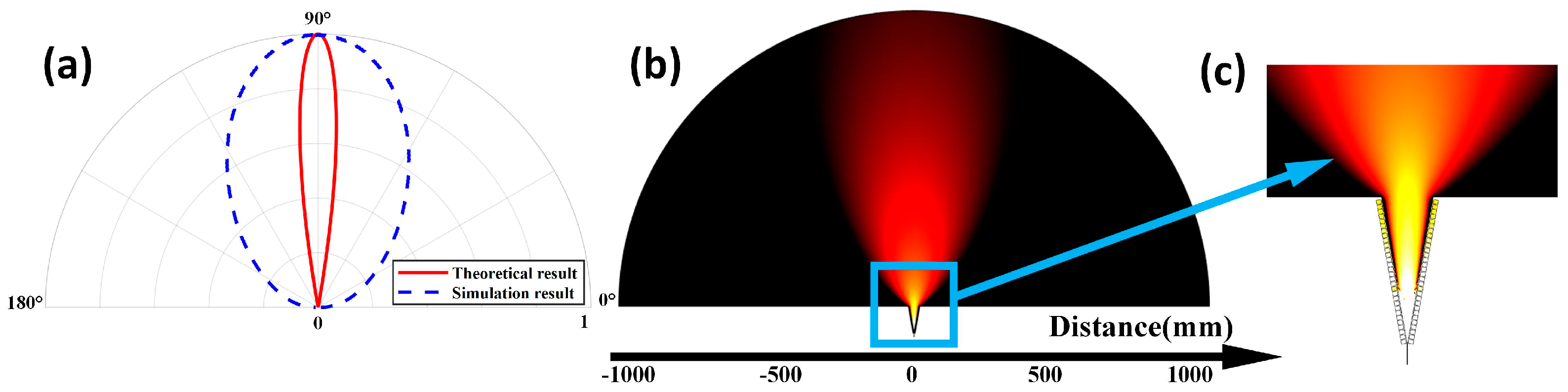
2.4. Results and Discussion

In the directivity map, we took the width of the main lobe as the evaluation criterion; the directionality worsens with increasing width. Second, the accuracy of the theory was judged by comparing the theoretical and experimental directivity diagrams. Figure 2a shows that for the structure proposed in this paper, the width of the main lobe is much smaller than the structure with only one slit, and the directivity of the sound wave passing through the slit is significantly improved. The theoretical results in Figure 2 are consistent with the simulation results. Quadrupole-like radiation patterns are obtained from the experiment, which is in line with the numerical simulations and theoretical predictions. Overall, the experimental results agree well with the theoretical results. This structure significantly improves plane wave directivity without any sidelobe. Moreover, the radiation properties can be adjusted by changing the parameter α .
As α increases in Figure 2a–c, the radiation properties of the structures approach those of a dipole. However, if α is too small, the difference between the interface and the slit will be small, and the acoustic energy will be bound inside the structure. The numerical simulation produces the result in Figure 4c when | Z s / ρ 0 c 0 | 0 and α = 10 ° .

3. Asymmetric Structure

3.1. Theoretical Analysis

On the basis of the above results, the structure can be changed to asymmetric, as shown in Figure 5a. The angle between the left and right interfaces is β + γ . This structure is equivalent to the original structure, with α = β + γ 2 and deflection Δ α = | β γ | 2 . In the same coordinate system as before, the directivity formula can be written as
D P ( θ ) = | cos ( θ + Δ α α ) cos ( θ + Δ α + α ) | .

3.2. Numerical Simulation

When HRs resonate, | Z s / ρ 0 c 0 | 0 , and a quadrupole-like radiation pattern with a certain deflection angle is obtained, as shown in Figure 5b. Figure 5c shows the simulated and theoretical results for | Z s / ρ 0 c 0 | 0 , β = 30 ° , and γ = 45 ° , with 31 HRs in total, 14 units on the left, and 17 units on the right.

3.3. Results and Discussion

From Figure 5b,c, the numerically simulated deflection angle is mostly consistent with the theoretical result of Δ α = | β γ | 2 = 7.5 ° . The theory is basically correct. Therefore, we can adapt the radiation direction according to | β γ | 2 . Theoretically, the maximum difference between β and γ is 90°, thus the structure can deflect the radiation direction by at most 45°.

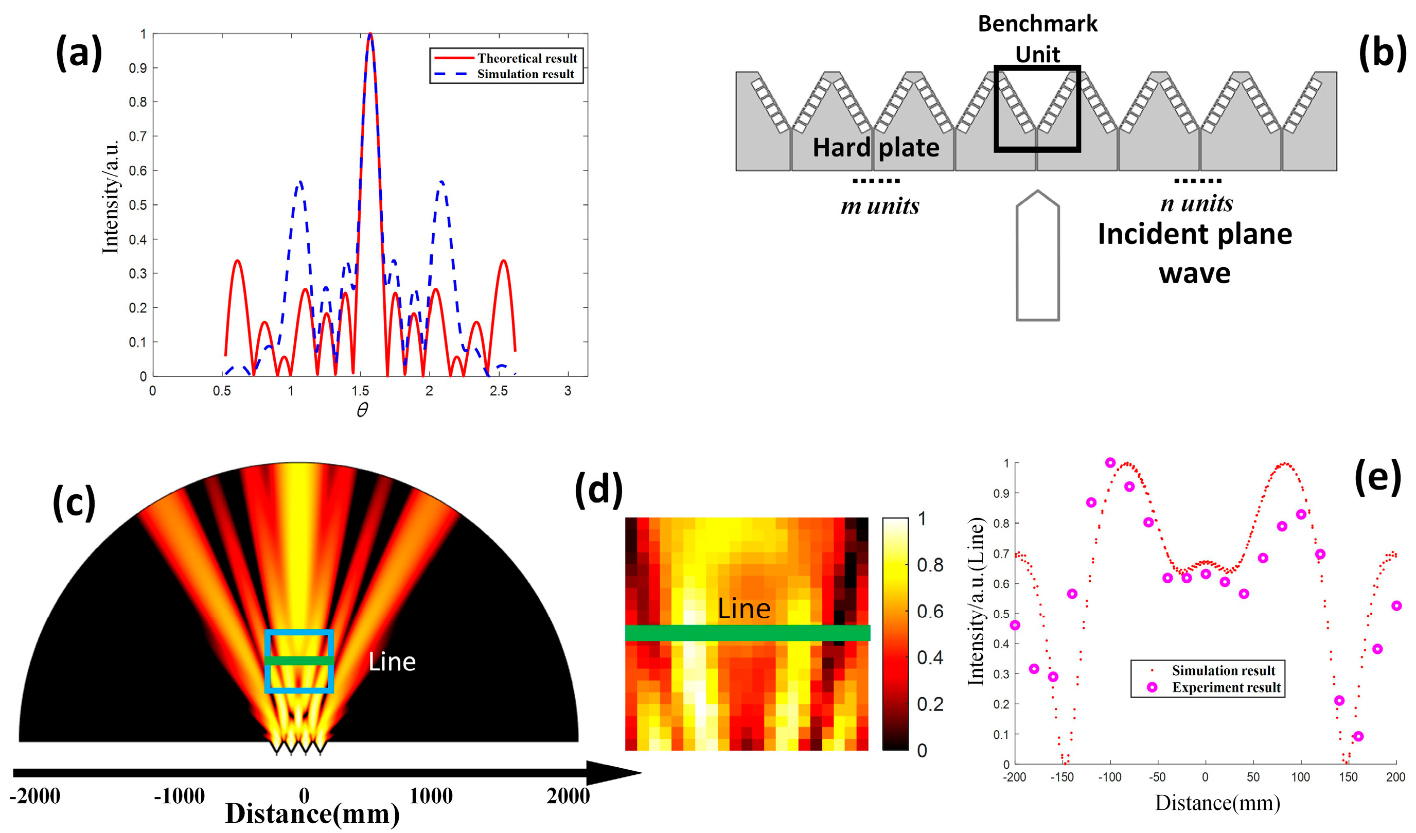
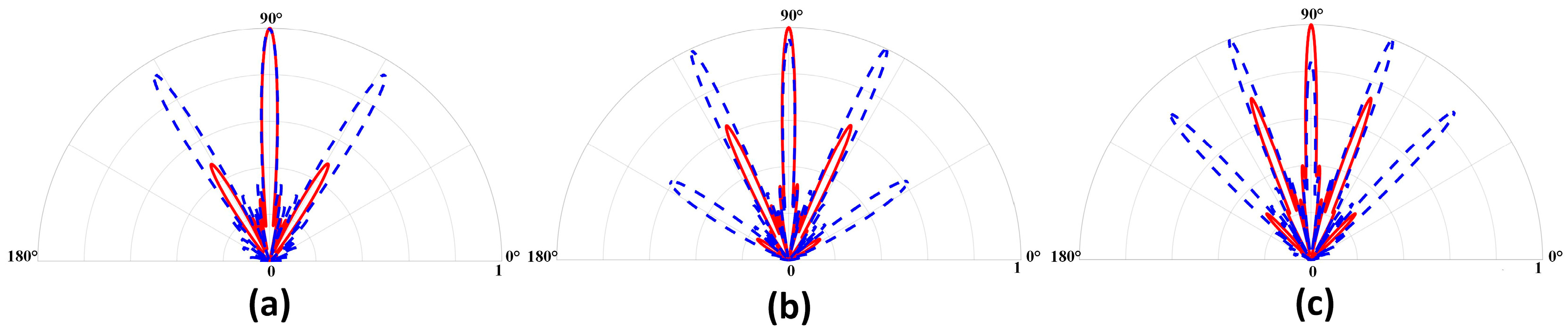
4. Linear Array of Quadrupole Sources

4.1. Theoretical Analysis

A linear array structure with quadrupole sources is proposed to obtain better acoustic directivity, as shown in Figure 6b. As seen from Figure 6b, the structure consists of multiple quadrupoles arranged horizontally. We assume that all the quadrupole sources have the same phase and volume velocity when | Z s / ρ 0 c 0 | 0 . One benchmark unit is selected from the linear quadrupole array, its center is used as the starting point, and the unit is arranged at both ends with the same array distance. There are m units on the left and n units on the right, assuming that all units have the same pointing angle θ in the far field when the number of structural units is not large. The velocity potential at the observed point P can be approximated as
Φ P = k 2 d 2 A 2 r sin 2 α e j ( ω t k r ) cos ( θ α ) cos ( θ + α ) i = n m e j k i Δ l cos θ
Assuming k 2 d 2 A 2 r sin 2 α e j ( ω t k r ) = K , the expression for the velocity potential at the observed point is obtained as
Φ P = K e 1 2 j k ( m n ) Δ l cos θ cos ( θ α ) cos ( θ + α ) sin [ 1 2 k ( m + n + 1 ) Δ l cos θ ] sin ( 1 2 k Δ l cos θ ) .
Here, the directivity of the linear array with quadrupole sources can be written as
D P ( θ ) = | cos ( θ α ) cos ( θ + α ) sin [ π Δ l λ ( m + n + 1 ) cos θ ] sin ( π Δ l λ cos θ ) | .

4.2. Numerical Simulation and Experiment

The chosen number of linear array units was four, the distance between units was 2 λ , the incident sound frequency was 6650 Hz, and α was 30°. The theoretical and simulated results are shown in Figure 6a,c. The experimental sound pressure map is also presented in Figure 6d. The experimental method and environment are the same as in Section 2.3. To better compare the experimental and simulated results, we selected the position “Line” labelled in Figure 6c,d, and plotted the relationship between the normalized sound pressure and position, as shown in Figure 6e.

4.3. Comparison between Quadrupole and Dipole Linear Arrays

We also studied the effect of array distance on directivity for the quadrupole and dipole linear arrays. Owing to the size limitations of the quadrupole array, we took Δ l / λ = 2 , Δ l / λ = 2.5 , and Δ l / λ = 3 for α = 30 ° , m + n + 1 = 5 , and f = 6650 Hz to ensure that each unit could maintain equivalent quadrupole characteristics. The directivity diagrams are drawn in Figure 7a–c.

4.4. Results and Discussion

Figure 6a shows some differences between the theoretical results and the simulations, although the main lobe is almost the same. This difference is mainly in the sidelobe. The lateral lobe close to the main lobe is smaller in the theoretical result than in the simulation, and the sidelobe away from the main lobe is larger. The reason is that we have assumed the radiation angle selected by each unit is the same as the benchmark unit, when, in fact, the angles of other units are not exactly the same, except when the angle of the benchmark unit is θ . The radiation angle of the units left of the benchmark unit is actually larger, while the radiation angle right of the benchmark is actually smaller, and the radiation angle deviation increases with greater distance between each unit and the benchmark unit. When the number of structural units is large, the difference in the radiation angle of each unit should be considered. In contrast, the number of structural units is not large, and the pointing angle of each unit is almost the same. However, the error is much larger when the angle is close to 0 ° or 180 ° . The experimental results are very consistent with the numerical results [Figure 6a,e], which verifies our theoretical predictions. In Figure 6, it is obvious that the main lobe of the linear array becomes narrower and the directivity is better than that of Figure 2.
Figure 7 shows that the main lobe of the quadrupole linear array is approximately the same as that of the quasi-dipole linear array for a suitable element distance, while the sidelobe peak of the quadrupole array is smaller than that of the quasi-dipole array. Moreover, the sidelobe becomes larger as the distance between array elements increases. The peak value of the sidelobe gradually approaches that of the main lobe, and the directivity of the linear array worsens.

5. Conclusions

We have produced a type of metamaterial that can achieve radiation in a single direction, has a simple configuration, and is easy to fabricate. The directivity of the acoustic radiation at low frequency can be enhanced by equivalent quadrupolar sources with acoustic metamaterials. Compared with a dipole, this metamaterial produces radiation with higher directivity and higher efficiency. The numerical and experimental results agree well with the theoretical predictions, thus providing a new scheme for modulating acoustic waves. The asymmetric structure based on this mechanism provides a flexible method of adjusting radiation directions. Moreover, the linear array of quadrupole sources in this structure achieves better directivity than that of a dipole.
It is noteworthy that the quadrupole-like radiation has high efficiency and relatively wide bandwidth. Moreover, the quadrupole-like radiation does not have any sidelobe. This mechanism for achieving directional radiation can used in devices, such as high-gain loud speakers and ultrasonic medical instruments. In the future, we hope to apply this structure to sound localization and other functions.

Author Contributions

Conceptualization, Q.Z. and X.L.; methodology, Q.Z., S.G. and X.L.; software, Q.Z.; validation, Q.Z., X.L. and Y.L.; formal analysis, Q.Z.; investigation, Q.Z. and S.G.; resources, X.L.; data curation, Q.Z. and S.G.; writing—original draft preparation, Q.Z.; writing—review and editing, X.L. and S.G.; visualization, Q.Z.; supervision, Yun Lai and X.L.; project administration, X.L.; funding acquisition, X.L. All authors have read and agreed to the published version of the manuscript.

Funding

This project was funded by the National Key R&D program of China (Grant No. 2020YFA0211400), the State Key Program of National Natural Science of China (Grant No. 11834008), the National Natural Science Foundation of China (Grant No. 12174192, No. 11974176, No. 12174188), the State Key Laboratory of Acoustics, Chinese Academy of Sciences (Grant No. SKLA202210), the Key Laboratory of Underwater Acoustic Environment, Chinese Academy of Sciences (Grant No. SSHJ-KFKT-1701).

Informed Consent Statement

Informed consent was obtained from all subjects involved in the study.

Data Availability Statement

Data Availability Statements in section “MDPI Research Data Policies” at https://www.mdpi.com/ethics accessed on 4 January 2023.

Conflicts of Interest

The authors declare no conflict of interest.

Appendix A

Table A1. Symbols in paper and their meanings.
SymbolMeaningSymbolMeaning
ρ 0 The density of the medium. c 0 Sound velocity of the medium.
Z s The acoustic impedance of the structural interface. θ The angle of the OP and the horizontal plane.
2 α The angle between the left and right interfaces of proposed structure. r i ( i = 1 , 2 , 3 , 4 ) The distance between each point sound source and point P.
Φ i ( i = 1 , 2 , 3 , 4 ) The velocity potential of each point sound source at the point P. Φ P The total velocity potential at point P (Radiation angle).
AThe amplitude of the velocity potential of each point sound source. k The wave number of the incident sound.
ω The angular frequency. λ The wavelength.
j The imaginary unit. 2 d The distance between the two positive source.
r The distance from O to P. D P ( θ ) The theoretically directivity.
β The angle between the left interface and the central axis of the asymmetric structure. γ The angle between the right interface and the central axis of the asymmetric structure.
fFrequency of acoustic waves. Δ l Distance between the array units.
mThe number of units on the left of benchmark unit.nThe number of units on the right of benchmark unit.
Figure A1. Simulation interface screenshots.
Crystals 13 00101 g0a1
Table A2. Detailed information of the experimental instrument.
InstrumentDetailed Information
Stepping motor Made by Nanjing Stepping Motor Factory and the scan accuracy is 1 mm
Digital Storage oscilloscopeInfiniiVision DSO-X 3034A
Travelling microphoneBeijing AcousticSensing Technology, 1/2″ Microphone.Type:CHZ-213 + YG-201
OPen-circuit Sensitivity Level: −27.6dB re 1 V/pa or 41.6 mV/Pa
Speaker arrayParticularly custom-made, each unit can make sounds in the range of 20–20,000 Hz

References

  1. Perez-Arjona, I.; Sanchez-Morcillo, V.J.; Redondo, J.; Espinosa, V.; Staliunas, K. Theoretical prediction of the non diffractive propagation of sonic waves through periodic acoustic media. Phys. Rev. B 2007, 75, 014304. [Google Scholar] [CrossRef] [Green Version]
  2. Cebrecos, A.; Rommero-Garcia, V.; Picó, R.; Pérez-Arjona, I.; Espinosa, V.; Sánchez-Morcillo, V.J.; Staliunas, K. Formation of collimated sound beams by three-dimensional sonic crystals. J. Appl. Phys. 2012, 111, 104910. [Google Scholar] [CrossRef] [Green Version]
  3. Li, B.; Deng, K.; Zhao, H. Acoustic guiding and subwavelength imaging with sharp bending by sonic crystal. Appl. Phys. Lett. 2011, 99, 051908. [Google Scholar] [CrossRef] [Green Version]
  4. Qiu, C.; Liu, Z. Acoustic directional radiation and enhancement caused by band-edge states of two-dimensional phononic crystals. Appl. Phys. Lett. 2006, 89, 063106. [Google Scholar] [CrossRef]
  5. Ke, M.; Liu, Z.; Pang, P.; Qiu, C.; Zhao, D.; Peng, S.; Shi, J. Experimental demonstration of directional acoustic radiation based on two-dimensional phononic crystal band edge states. Appl. Phys. Lett. 2007, 90, 083509. [Google Scholar] [CrossRef]
  6. Soliveres, E.; Espinosa, V.; Perez-Arjona, I.; Sanchez-Morcillo, V.J.; Staliunas, K. Self collimation of ultrasound in a three-dimensional sonic crystal. Appl. Phys. Lett. 2009, 94, 164101. [Google Scholar] [CrossRef]
  7. Xu, X.; Feng, Y.; Jiang, T. Electromagnetic beam modulation through transformation optical structures. New J. Phys. 2008, 10, 115027. [Google Scholar] [CrossRef]
  8. Chen, S.; Fan, Y.C.; Fu, Q.H.; Wu, H.J.; Jin, Y.B.; Zheng, J.B.; Zheng, F.L. A Review of Tunable Acoustic Metamaterials. Appl. Sci. 2018, 8, 1480. [Google Scholar] [CrossRef] [Green Version]
  9. Chen, Q.; Zhang, B.; Bai, Y.; Wang, L.; Rejab, M.R.M. Review of Phononic crystals and acoustic metamaterials. IOP Conf. Ser. Mater. Sci. Eng. 2020, 788, 1757–8981. [Google Scholar] [CrossRef]
  10. Tong, S.; Ren, C.; Tao, J.; Tang, W. Anisotropic index-near-zero metamaterials for enhanced directional acoustic emission. J. Phys. D 2020, 53, 265102. [Google Scholar] [CrossRef]
  11. Tao, J.; Tong, S.; Ren, C. Anisotropic density-near-zero metamaterials for enhanced directional and aperture-adjustable acoustic emission. J. Phys. D 2021, 54, 485102. [Google Scholar] [CrossRef]
  12. Tong, S.; Ren, C.; Tao, J. Compact topological waveguide for acoustic enhanced directional radiation. Appl. Phys. Lett. 2022, 120, 063504. [Google Scholar] [CrossRef]
  13. Quan, L.; Zhong, X.; Liu, X.; Gong, X.; Johnson, P.A. Effective impedance boundary optimization and its contribution to dipole radiation and radiation pattern control. Nat. Commun. 2014, 5, 3188. [Google Scholar] [CrossRef] [PubMed] [Green Version]
  14. Wilson, G.P.; Sorka, W.W. Approximation to the diffraction of sound by a circular aperture in a rigid wall of finite thickness. J. Acoust. Soc. Am. 1965, 37, 286–297. [Google Scholar] [CrossRef]
  15. Ciaburro, G.; Lannace, G. Membrane-type acoustic metamaterial using cork sheets and attached masses based on reused materials. Appl. Acoust. 2022, 189, 070206. [Google Scholar] [CrossRef]
  16. Lobanov, S.V.; Weiss, T.; Dregely, D.; Giessen, H.; Gippius, N.A.; Tikhodeev, S.G. Emission properties of an oscillating point dipole from a gold Yagi-Udanano antenna array. Phys. Rev. B 2012, 85, 155137. [Google Scholar] [CrossRef] [Green Version]
  17. Ding, E.; Mao, Y.; Liu, X. Realizing a finite array of dipole sources with high acoustic transmission directivity at low frequency. J. Acoust. Soc. Am. 2017, 1413, 1936–1939. [Google Scholar] [CrossRef] [PubMed]
  18. Zhou, Y.; Lu, M.-H.; Feng, L.; Ni, X.; Chen, Y.-F.; Zhu, Y.-Y.; Zhu, S.-N.; Ming, N.-B. Acoustic surface evanescent wave and its dominant contribution to extraordinary acoustic transmission and collimation of sound. Phys. Rev. Lett. 2010, 104, 164301. [Google Scholar] [CrossRef] [PubMed]
Figure 1. Mechanism for realizing a quadrupolar resonance. (a) Schematic of the structure. (b) Equivalent schematic of the structure, implying a quadrupolar resonance, the positive sources are red and negative sources are blue.
Crystals 13 00101 g001
Figure 2. Simulation and experimental verification of directional radiation. Theoretical, simulated, and experimental normalized directivity diagram for | Z s / ρ 0 c 0 | 0 and (a) α = 30 ° , (b) α = 45 ° , and (c) α = 60 ° ; the pink line in (a) is the simulation result for the structure with only one slit. Simulated sound pressure map for | Z s / ρ 0 c 0 | 0 and (d) α = 30 ° , (e) α = 45 ° , and (f) α = 60 ° . Experimental sound pressure map for | Z s / ρ 0 c 0 | 0 and (g) α = 30 ° , (h) α = 45 ° , and (i) α = 60 ° .
Crystals 13 00101 g002
Figure 3. (a) Sample. (b) Diagram of the experimental system. (c) Travelling microphone. (d) Sound source. (e) Test environment.
Crystals 13 00101 g003
Figure 4. Theoretical and simulated sound fields induced by the structure for α = 10 ° and | Z s / ρ 0 c 0 | 0 . (a) Theoretical and simulated directivity diagrams. (b) Simulated sound pressure map. (c) Locally magnified image of the sound pressure map.
Crystals 13 00101 g004
Figure 5. (a) Schematic of the structure. (b) Simulated sound pressure for | Z s / ρ 0 c 0 | 0 . (c) Theoretical and simulated sound fields induced by the structure.
Crystals 13 00101 g005
Figure 6. (a) Comparison of theoretical and simulated quadrupole linear arrays for | Z s / ρ 0 c 0 | 0 . (b) Simulated sound pressure for | Z s / ρ 0 c 0 | 0 . (c) Schematic of the quadrupole linear array. (d) Experimental sound pressure for α = 30 ° , Δ l / λ = 2 , and | Z s / ρ 0 c 0 | 0 . (e) Comparison between the experimental and simulated results at “Line”.
Crystals 13 00101 g006
Figure 7. Comparison of simulated directivities between linear arrays of dipole sources and linear arrays of quadrupole sources with different Δ l / λ values for five units. The blue and red lines are the results for the dipole and quadrupole arrays, respectively. (a) Δ l / λ = 2 , (b) Δ l / λ = 2.5 , and (c) Δ l / λ = 3 .
Crystals 13 00101 g007
Table 1. Characteristics of the structures used in the experiment.
Structural TypesMaterialWidth
(mm)
Height
(mm)
Thickness
(mm)
Slit Width (mm)Slit Length (mm)
α = 30 ° resin1049934225
α = 45 ° resin1328734225
α = 60 ° resin1646834225
Disclaimer/Publisher’s Note: The statements, opinions and data contained in all publications are solely those of the individual author(s) and contributor(s) and not of MDPI and/or the editor(s). MDPI and/or the editor(s) disclaim responsibility for any injury to people or property resulting from any ideas, methods, instructions or products referred to in the content.

