Article

Microstructure Evolution of Reactor Pressure Vessel A508-3 Steel under High-Dose Heavy Ion Irradiation

Sino-French Institute of Nuclear Engineering and Technology, Sun Yat-sen University, Zhuhai 519082, China
*
Authors to whom correspondence should be addressed.
Crystals 2022, 12(8), 1091; https://doi.org/10.3390/cryst12081091
Submission received: 24 May 2022 / Revised: 18 July 2022 / Accepted: 1 August 2022 / Published: 4 August 2022

Abstract

:
The microstructure evolution of nuclear reactor pressure vessel A508-3 steel irradiated by heavy ions up to 1.5 dpa was studied by transmission electron microscopy (TEM). According to the TEM analysis, black dots were widely distributed in the irradiated A508-3 steel, with a high density of 1.782 × 10²²/m3. A large number of dislocations with Burgers vectors <100> were formed in the irradiated A508-3 steel and tangled together, leading to the formation of dislocation networks. The number density of black dots at 1.5 dpa was 3.5 times higher than that at 0.08 dpa, and the corresponding average size showed an 8% increase. The higher density of dislocation defects led to a significant increase in hardness from 3.0 GPa at 0.08 dpa to 4.2 GPa at 1.5 dpa. The elastic modulus showed a slight increase and less dependence on the irradiation dose.

1. Introduction

The reactor pressure vessel (RPV) is one of the most important components in a nuclear light-water power plant, and it is regarded as a life-limiting feature of the operation of a nuclear power plant if its mechanical properties degrade sufficiently [1]. Nowadays, extending the life of nuclear power plants is an important concern due to the remarkable economic benefits conferred by an extension of 40, 60, or even 80 years [2,3]. Several factors are essential for the safe operation of nuclear power plants during life extension. For instance, after decades of service under neutron irradiation, RPV steel exhibits degradation in its mechanical properties, i.e., irradiation hardening and irradiation embrittlement [4,5]. To be specific, matrix defects, such as dislocation loops induced by irradiation and radiation-induced segregation and precipitation (RIS and RIP), act as obstacles to dislocation movement, which causes hardening and embrittlement due to irradiation [6].
On the one hand, regarding matrix defects, after the cascade collision of thermal neutrons with the metal atoms in RPV steel, neutron irradiation mainly results in various defects and dislocation loops in the steel lattice, leading to different deformation mechanisms that affect crack initiation and the tolerance to cracks [7]. In [8], a study on the ion irradiation of RPV steel, the ion doses were 0.1, 0.5, and 1.0 dpa. It was found that after irradiation, the densities of the defects in the reactor pressure vessel steel and pure Fe increased, the defects were vacancy-type and solute-cluster-type, and the irradiation hardening increased as the dose increased in both the reactor pressure vessel steel and pure Fe.
On the other hand, regarding precipitation, certain elements (including Cu, Ni, Mn, and P) increase the irradiation embrittlement of RPV steel [9,10]. It is known that the tensile properties and fracture toughness of irradiated RPV steel are closely related to its microstructure and damage due to irradiation [11]. Moreover, Belkacemi L.T. et al. [12] found that the irradiation-induced mechanism is involved in the atomic transportation towards the microstructural defects in FeNi alloys. Bergner F. et al. [13] found that nanovoids are stronger obstacles for dislocation glide than dislocation loops, whereas dislocation loops are stronger than Cu-rich clusters (CRPs). Nevertheless, CRPs contributed the most to irradiation hardening because of their high number density. Nanosized voids were only observed for the neutron fluences beyond the typical end-of-life conditions of RPVs.
The RPVs of pressurized water reactors (PWRs) in China are mainly made of A508-3 steels, received from China General Nuclear Power Group, Guangdong, China with a low concentration of copper and phosphorus, which are designed to have good irradiation resistance, mechanical strength, and fracture toughness. However, it is still important to study the microstructure evolution of RPV steel under irradiation. To evaluate the life extension of a nuclear power plant, the microstructure evolution of the RPV steel is a critical concern. One of the key embrittlement mechanisms in RPV steel is the hardening produced by irradiation damage, especially the dislocation loops. There are not enough high-dose irradiation data concerning RPV steel. The high irradiation damage effect on RPV steel needs to be further studied to better assess its life-limiting status. In this study, we investigated the matrix defects in Chinese A508-3-type reactor pressure vessel steel irradiated by Fe ions with 1.5 dpa at room temperature.

2. Materials and Methods

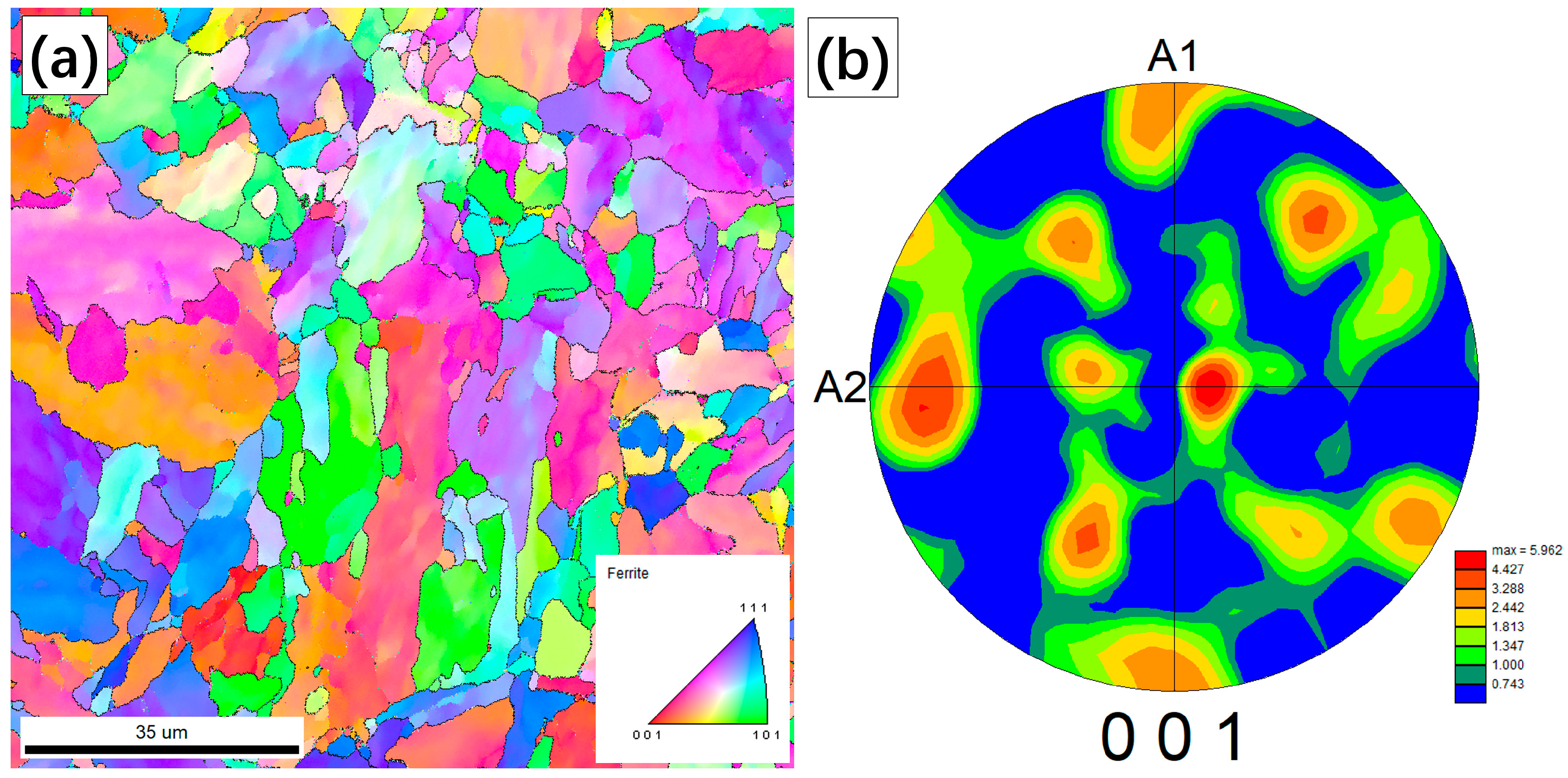
2.1. Materials and Microstructural Characterization

The chemical composition of Chinese A508-3 steel is shown in Table 1. Specimens with a size of 6 mm × 6 mm × 0.5 mm were cut from a reactor pressure vessel shell; mechanically ground using SiC grit paper of 600, 800, 1000, 1500, and 2000 mesh; and polished by a diamond suspension of 9 µm, 3 µm, and 1 µm in turn. Then, the surface of the specimen was vibration-polished with 0.05 µm polishing solution. Finally, ultrasonic cleaning in acetone, alcohol, and deionized water was performed to remove the impurities and contaminants on the surface. Figure 1 shows the electron backscatter diffraction (EBSD) results of the original samples. It can be seen that the original sample with a BCC structure had a grain size of about 15 µm and showed no preferred orientation.

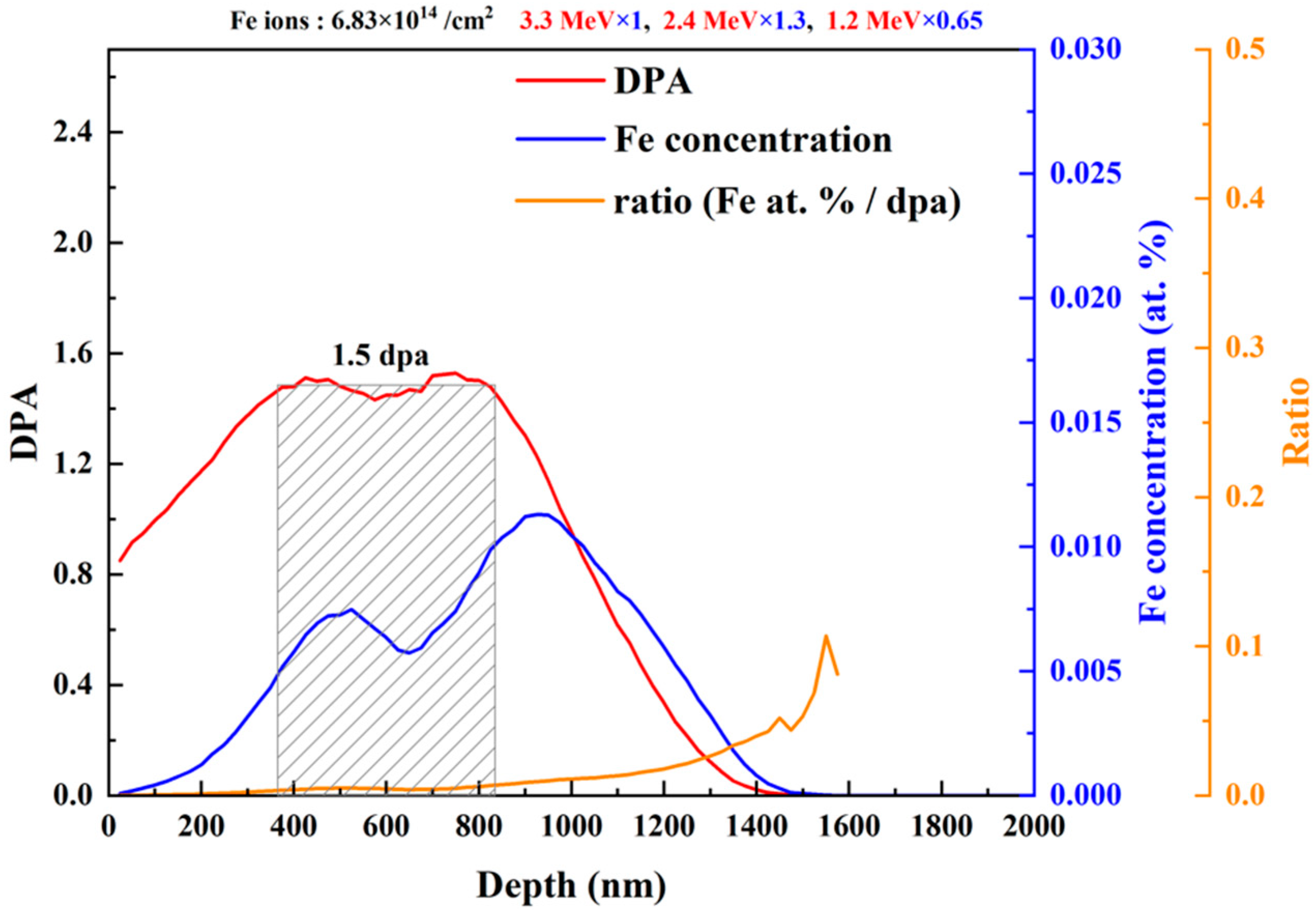
2.2. Ion Irradiation Test

The sample was irradiated at room temperature (RT) using the tandem accelerator in School of Physics and Technology, Wuhan University, Hubei, China. During irradiation, the specimen was held in place using an adhesive with good electrical and thermal conductivity. The uniform Fe+ ion beam with a cross-sectional area of 6 × 6 mm was directed in front of the target to cover the entire sample surface. The damage per atom (dpa) in the Chinese A508-3 steel was calculated by SRIM-2013 using the Kinchin–Pease model with quick calculation [14]. As a result, three Fe+ ion beams with different energies (1.2, 2.4, and 3.3 MeV) and fluences were used to obtain an irradiation damage plateau with an irradiation depth of ~1.5 µm; the corresponding simulation results are shown in Figure 2. It should be noted that the threshold displacement energy (Ed) of the major elements (Fe, Mn, Ni, and Mo) was set to 40 eV during the calculation of irradiation damage. The fluence of 3.3 MeV Fe+ ions was the benchmark, and the fluences of 2.4 MeV and 1.6 MeV Fe+ ions were multiplied by 1.3 and 0.65, respectively. Damage (dpa) and Fe concentration (at. %) were calculated using Formulas (1) and (2) from SRIM’s output files:
vacancy . txt ( vacancies ions × A ˙ ) × ( 10 8 ( A ˙ / cm ) × Fluence ( ions / cm 2 ) 8.46 × 10 22 ( atoms / cm 3 ) ) =   dpa
range . txt ( atoms / cm 3 atoms / cm 2 ) × ( Fluence ( ions / cm 2 ) 8.46 × 10 22 ( atoms / cm 3 ) ) × 100 =   at .   %
The irradiated sample suffered 1.5 dpa at room temperature with a fluence rate in the order of 10 11 / cm 2 · s . The irradiation damage plateau mainly ranged from 365 to 835 nm, and the deepest irradiation area reached 1500 nm. The ratio of Fe concentration to dpa was below 0.008 across the whole damage plateau. The damage plateau area met the requirements of a safe analysis region [15].

2.3. Transmission Electron Microscopy

A focused ion beam (FIB) device produced by FEI (Hillsboro, OR, USA), with the model FEI Helios NanoLab 600i in lift-out mode was used to cut a thin TEM specimen. Then, the irradiation defects of the RPV steel were analyzed by TEM. Cross-sectional TEM specimens ranging from the surface to ~1.5 µm were prepared, and the thickness of the specimen displaying irradiation damage was measured as 88.1 nm.

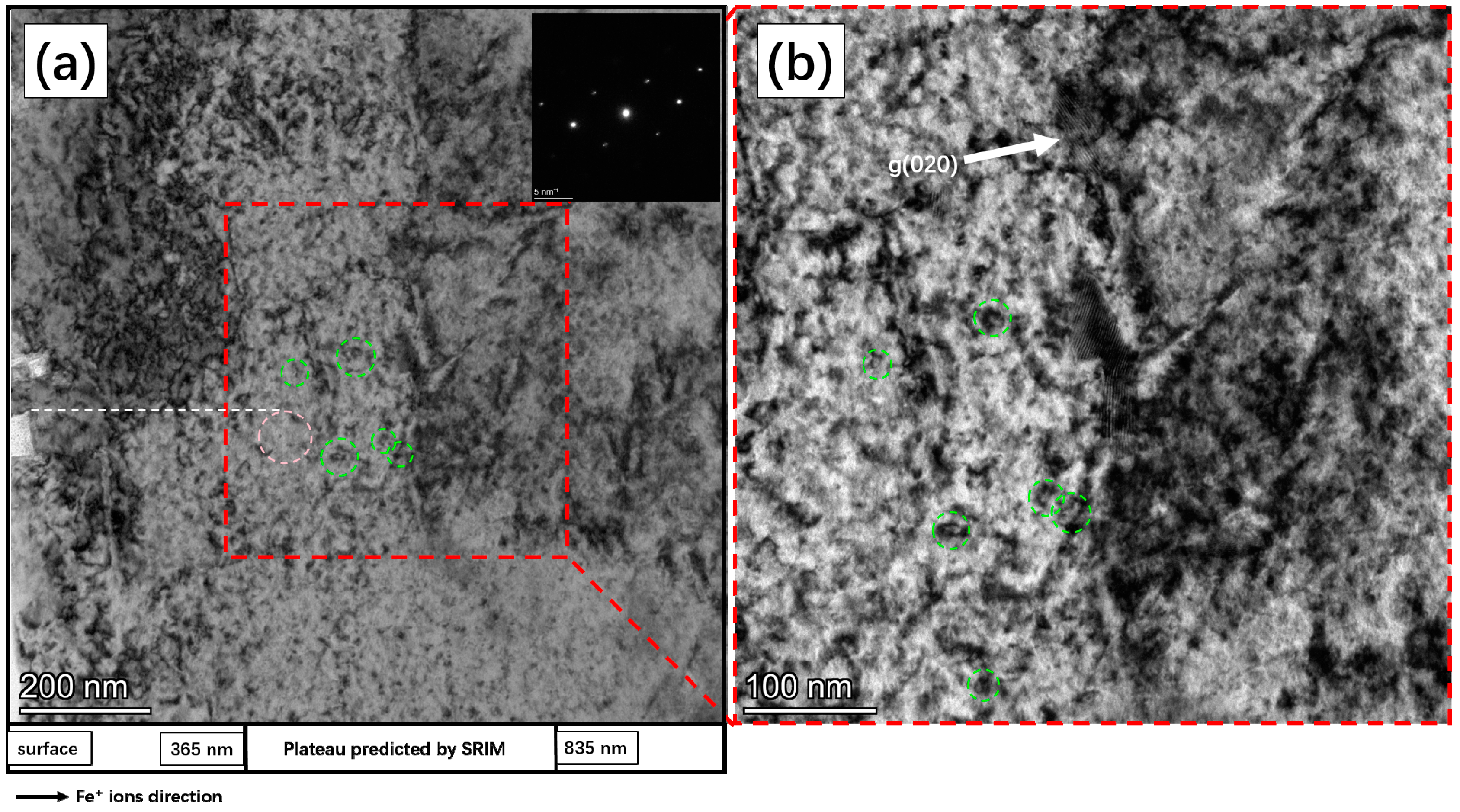
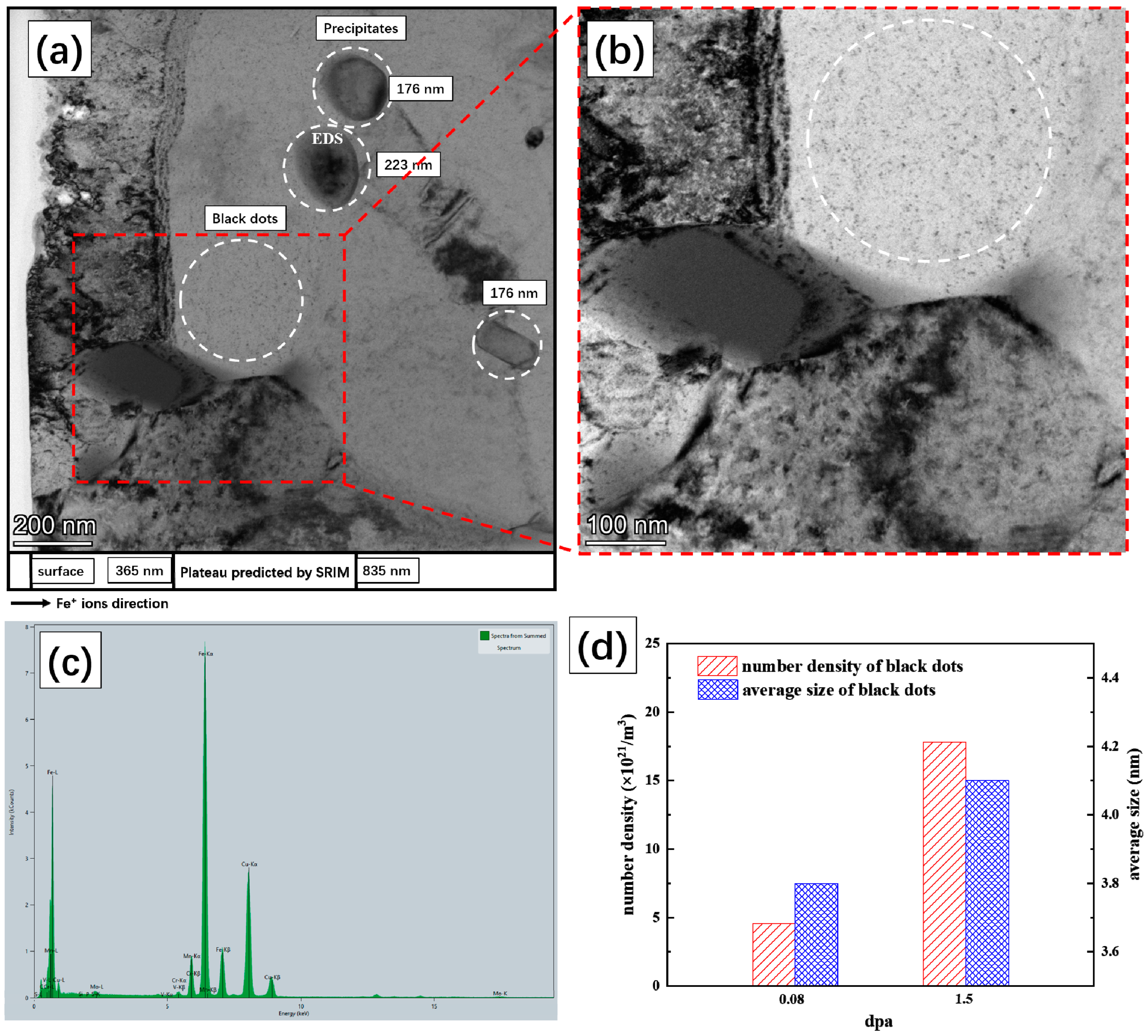
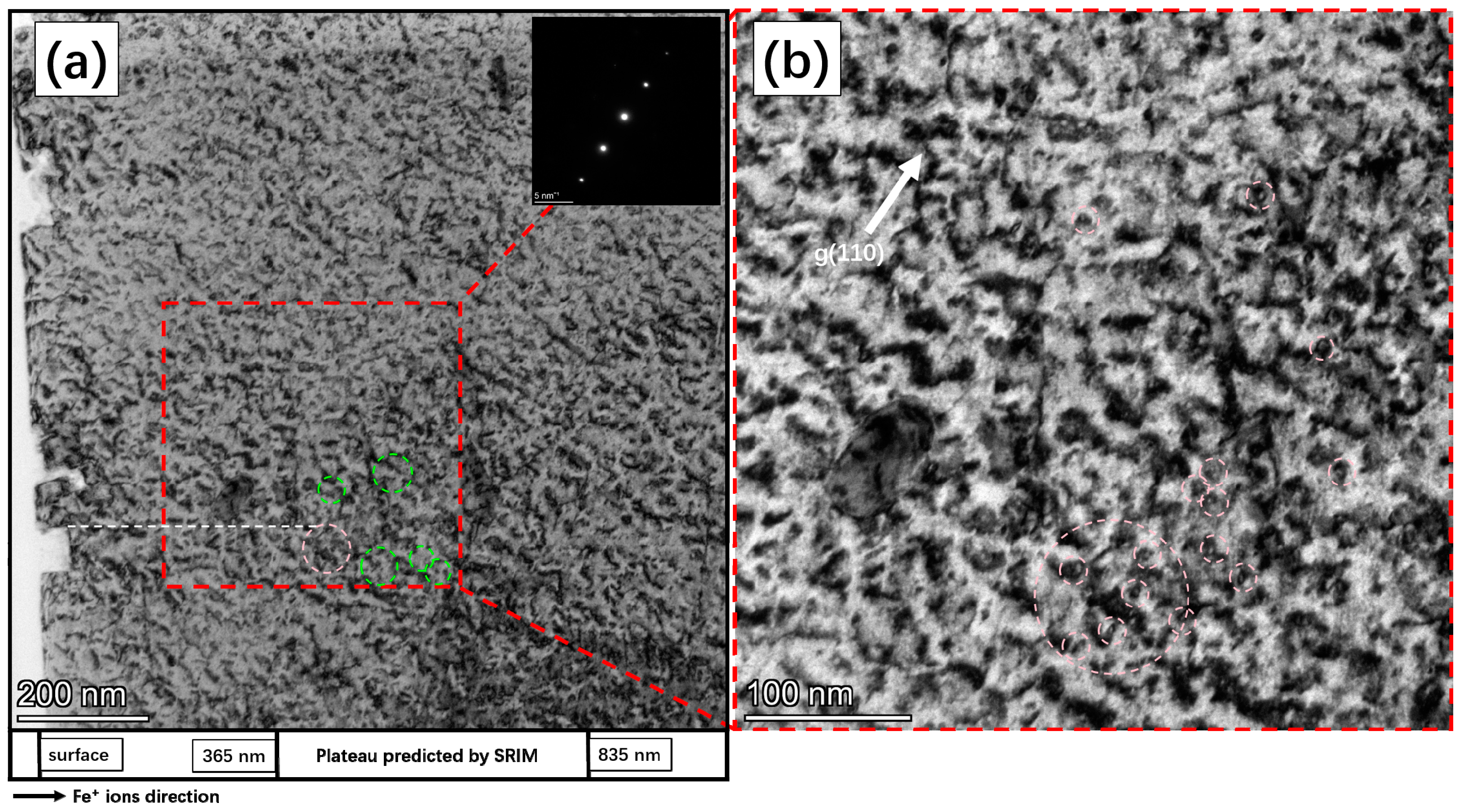
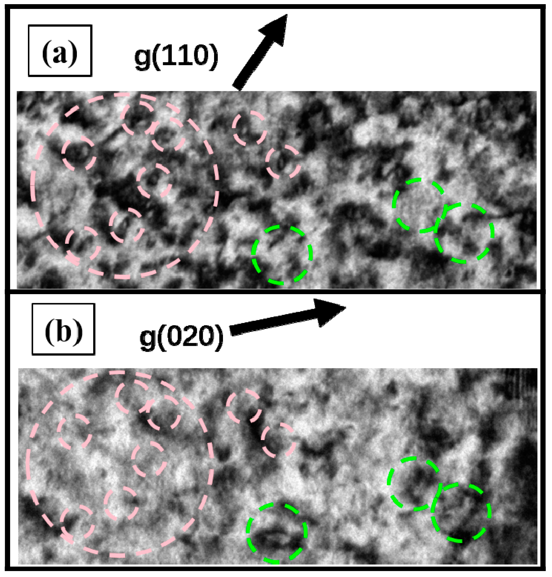
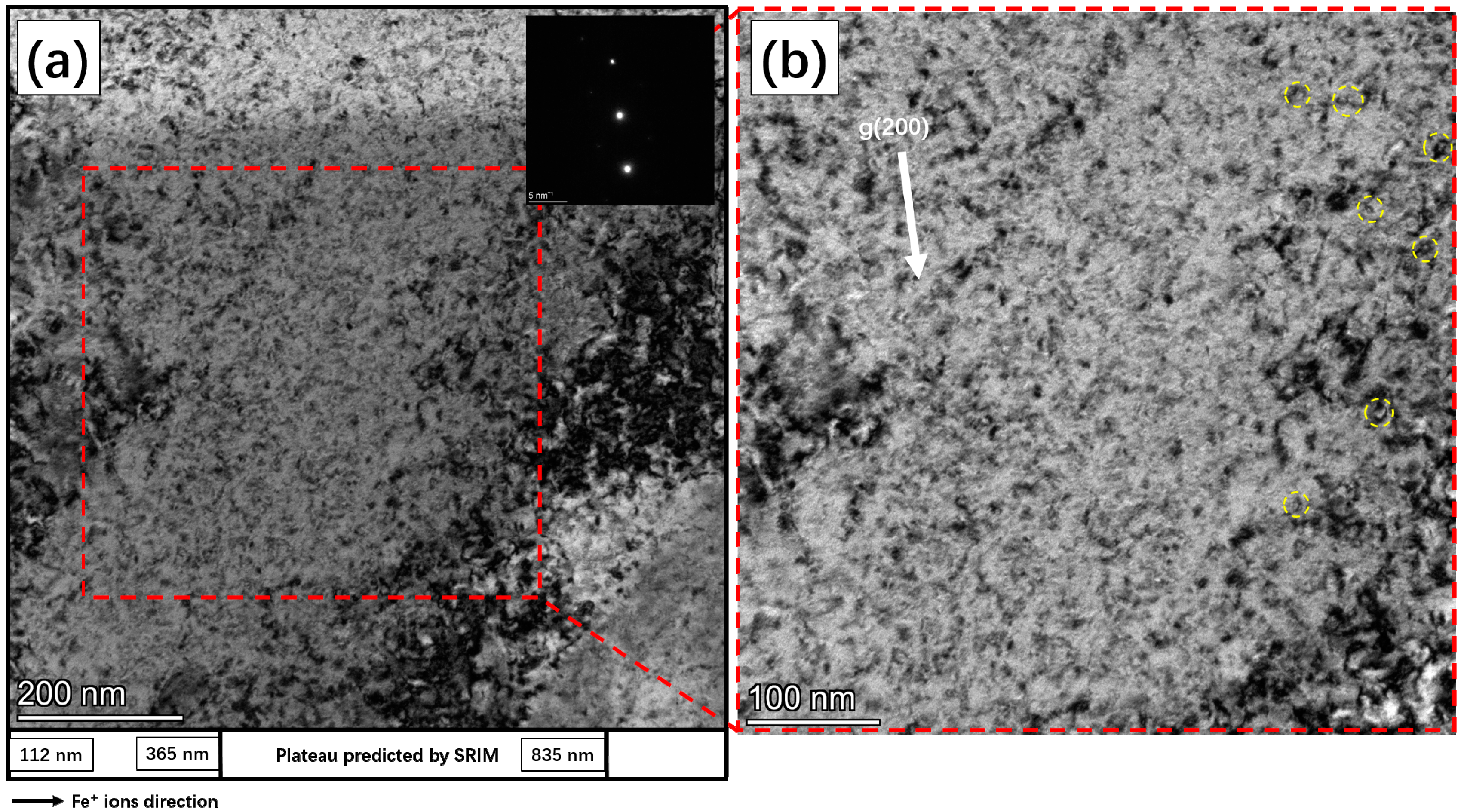
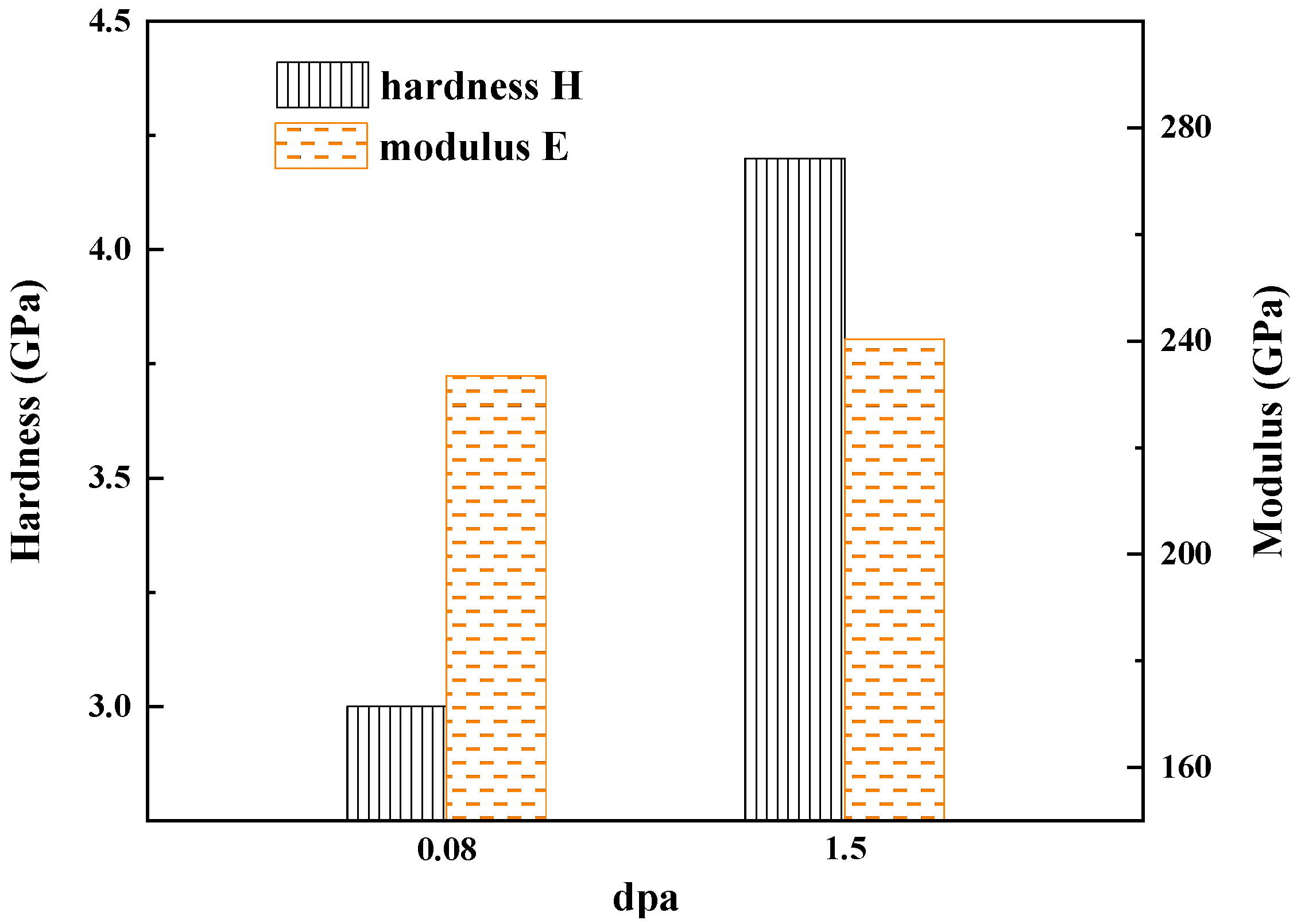
3. Results and Discussion

Figure 3 shows the microstructure of the A508-3 steel irradiated by Fe+ ions with 1.5 dpa. It is worth noting that most of the observable black dots were located within the DPA plateau predicted by SRIM. Through a statistical analysis of the images, we determined that the density of black dots in Figure 3b is 1.782 × 10²² /m3. Furthermore, precipitates were also observed, with sizes varying from 170 nm to 230 nm. The chemical composition of the precipitates was measured by EDS, as shown in Figure 3c and Table 2, and the precipitates were confirmed as M23C6. To study the effect of the irradiation dose on the number density and average size of black dots, we counted and analyzed them in the same RPV steel at a lower dpa based on our previous work [16], as shown in Figure 3d. With the increase in the irradiation damage from 0.08 to 1.5 dpa, the density of black dots increased remarkably, and the maximum density was over 1022/m3. The average size of the black dots gradually increased from 3.8 nm to 4.1 nm. Ding Z. N. et al. [17] also studied the number density of dislocation loops in A508-3 steel after Fe ion irradiation at room temperature. They found that for the specimen irradiated to 1.0 dpa, the number density of black dots was 1.3 × 10²²/m3. It should be noted that the density of black dots reported in the above study was of the same order of magnitude as in the present study.
To distinguish the type of dislocation loops created by the irradiation, the rule of g · b   = 0 was used in the TEM analysis. It has been reported that the types of dislocation loop produced by ion irradiation are mainly a0 <100> and ½a0 <111> [18,19,20]. In this study, three different diffraction vectors, g = (110), (020), (200), were used to characterize the irradiation defects in roughly the same area. The visibility and disappearance conditions of the different types of dislocation loop in these diffraction vectors are shown in Table 3. For example, b   = [ 010 ] is visible in g   = ( 020 ) but not in g   = ( 200 ) , and b   = [ 100 ] is visible in g   = ( 110 ) but not in g   = ( 020 ) .
Figure 4a shows the microstructure of the A508-3 steel with diffraction vector g = (110) near the [001] zone axis. Figure 4b is a local enlargement of Figure 4a. It could be observed that the dislocations were produced throughout the matrix and were intertwined, leading to the formation of dislocation networks. In Figure 5, the bright filed (BF) images were taken using a diffraction vector g = (020) near the [001] zone axis. Obviously, the density of the visible dislocations was reduced compared with that in Figure 4. By comparing the visibility and invisibility conditions in Table 3, only the dislocations with a Burgers vector of b   = [ 100 ] disappeared as expected when the diffraction vector changed from g = (110) to g = (020), indicating that the dislocations primarily followed a Burgers vector of b   = [ 100 ] .
In order to study the type of dislocation loops under diffraction vectors g = (110) and g = (020) in more detail, we examined the differences between the same positions in Figure 6a,b, as marked by the pink and green circles. Many dislocation loops became invisible when the diffraction vector changed from g = (110) to g = (020). There were many dislocation loops with a Burgers vector of b   = [ 100 ] in the irradiated steel. Meanwhile, few dislocation loops became visible that indicated the existence of dislocation loops with Burgers vectors of b [ 1 1 ¯ 1 ] or b [ 1 1 ¯ 1 ¯ ] .
Figure 7 shows the TEM images of the irradiated RPV steel under the diffraction vector of g = (200). By comparing the visibility and disappearance conditions in Table 3, we noted that only the dislocations with a Burgers vector of b   = [ 010 ] disappeared when the diffraction vector changed from g = (110) to g = (200). The same phenomenon was seen in Figure 5, in which a sharp decline in the density of visible dislocations was observed. Therefore, it can be concluded that a large proportion of dislocations with Burgers vectors <100> are preferentially formed in irradiated A508-3 steels. Through in situ experiments, Yao Z. et al. [20] reported that most of the dislocation loops in Fe and Fe–18% Cr irradiated by 100 keV Fe ions (~1 dpa) at RT were of the <100> type, while a small proportion had a Burgers vector of the a/2 <111> type; these results are consistent with those obtained in the present study.
Moreover, a comparison of Figure 4b with Figure 5b and Figure 7b shows that the entanglement between two dislocation loops was reduced. It can be concluded that the reduced entanglement resulted from the invisibility of the dislocation loops with b   = 100 under the diffraction vector g = (020). It has been reported that b   = 100 dislocation loops are almost immovable [21,22] and can constantly absorb free-moving interstitial atoms or mobile b   = 1 / 2 111 dislocation loops, which eventually results in the growth of b   = 100 dislocation loops [23]. Finally, these large b   = 100 dislocation loops interacted with each other. Hence, there were some large dislocation loops entangled together in the high-damage-degree steel, as shown in Figure 4.
In order to study the effects of irradiation damage on the mechanical properties of the steel, we examined the variation in the hardness and elastic modulus as the irradiation dpa changed, as shown in Figure 8. The hardness was calculated from the equivalent volume hardness fitted by the Nix-Gao model [24]. It was evident that the hardness value increased with the damage degree, with a hardness of 3.0 GPa for 0.08 dpa and 4.2 GPa for 1.5 dpa. These results follow the same trend as the black dot size and density presented in Figure 3d, which is reasonable because the evolution of dislocation loops is one of the primary contributors to irradiation-induced hardening [25,26]. Hence, at a higher irradiation dose of 1.5 dpa, the high density of the dislocation defects promoted a sharp increase in the hardness of RPV steel. As for the elastic modulus, the RPV steel samples after irradiation with 0.08 dpa and 1.5 dpa showed values of 233.5 GPa and 240.3 GPa, respectively, demonstrating a slight increase but no significant variation.

4. Conclusions

In this study, the microstructural features of RPV A508-3 steel irradiated by Fe+ ions up to 1.5 dpa were investigated. The density of black dots in the irradiated A508-3 steel was measured as 1.782 × 10²²/m3 by TEM. A high number density of dislocation loops was produced in the RPV steel after high-dose irradiation. The analysis of the microstructure of the irradiated RPV steel under different diffraction vectors indicated that a large number of dislocations with Burgers vectors <100> were formed. The dislocations tangled together, leading to the formation of dislocation networks. The number density of black dots at 1.5 dpa was 3.5 times larger than that at 0.08 dpa, and the corresponding average size showed an 8% increase. The higher density of dislocation defects led to a significant increase in hardness from 3.0 GPa at 0.08 dpa to 4.2 GPa at 1.5 dpa. The high density of dislocation defects at a higher dpa led to pronounced irradiation hardening. The elastic modulus showed a slight increase and less dependence on the irradiation dose.

Author Contributions

Conceptualization, X.M. and L.S.; methodology, F.Z.; software, Q.Z. and W.Z.; validation, Q.Z., M.S. and W.Z.; formal analysis, Q.Z., M.S. and W.Z.; investigation, L.S.; resources, X.M.; data curation, L.S.; writing—original draft preparation, L.S.; writing—review and editing, X.M. and F.Z.; visualization, L.S.; supervision, X.M.; project administration, X.M.; funding acquisition, X.M. All authors have read and agreed to the published version of the manuscript.

Funding

This research was funded by the Guangdong Major Project of Basic and Applied Basic Research (2019B030302011); the National Natural Science Foundation of China (Grant Nos. U2032143, 11902370); the International Science and Technology Cooperation Program of Guangdong Province (2019A050510022); the Zhuhai–Hong Kong–Macao Science and Technology Cooperation Program of Zhuhai City, China (ZH2207-7301-210009-P-WC); the Key Research Project of Guangdong Province (2019B010943001, 2017B020235001); the Fundamental Research Funds for the Central Universities, Sun Yat-sen University (No. 22lgqb40, 22qntd1801); and the STRFML-2018-25 Fund of the Science and Technology on Reactor Fuel and Materials Laboratory, Nuclear Power Institute of China.

Institutional Review Board Statement

Not applicable.

Informed Consent Statement

Not applicable.

Data Availability Statement

All data included in this study are available upon request by contacting the corresponding author.

Conflicts of Interest

The authors declare no conflict of interest.

References

  1. Davies, L.M. A comparison of western and eastern nuclear reactor pressure vessel steels. Int. J. Press. Vessel. Pip. 1999, 76, 163–208. [Google Scholar] [CrossRef]
  2. Rogner, H.-H. World outlook for nuclear power. Energy Strategy Rev. 2013, 1, 291–295. [Google Scholar] [CrossRef]
  3. Slugen, V.; Hein, H.; Sojak, S.; Pecko, S.; Veternikova, J.S.; Petriska, M.; Sabelova, V.; Bartosova, I.; Stacho, M. German and Russian Irradiated Reactor Pressure Vessel Steels from PAS Point of View. Acta Phys. Pol. A 2014, 125, 726–728. [Google Scholar] [CrossRef]
  4. Kuleshova, E.A.; Fedotov, I.V. Annealing as a Technique for Estimating the Structural Elements Contribution to NPP Materials Service Properties. Phys. Met. Metallogr. 2019, 120, 763–769. [Google Scholar] [CrossRef]
  5. Lu, K.; Katsuyama, J.; Li, Y. Plasticity Correction on Stress Intensity Factor Evaluation for Underclad Cracks in Reactor Pressure Vessels. J. Press. Vessel. Technol. 2020, 142, 051501. [Google Scholar] [CrossRef]
  6. Kuleshova, E.A.; Gurovich, B.A.; Bukina, Z.V.; Frolov, A.S.; Maltsev, D.A.; Krikun, E.V.; Zhurko, D.A.; Zhuchkov, G.M. Mechanisms of radiation embrittlement of VVER-1000 RPV steel at irradiation temperatures of (50-400) degrees C. J. Nucl. Mater. 2017, 490, 247–259. [Google Scholar] [CrossRef]
  7. Lin, Y.; Yang, W.; Tong, Z.; Zhang, C.; Ning, G. Charpy impact test on A508-3 steel after neutron irradiation. Eng. Fail. Anal. 2017, 82, 733–740. [Google Scholar] [CrossRef]
  8. Zhang, T.; Wang, H.; Li, Z.; Schut, H.; Zhang, Z.; He, M.; Sun, Y. Positron Annihilation Investigation of Embrittlement Behavior in Chinese RPV Steels after Fe-Ion Irradiation. Acta Metall. Sin. 2018, 54, 512–518. [Google Scholar]
  9. Hawthorne, J.R. Irradiation Embrittlement. Treatise Mater. Sci. Technol. 1983, 25, 461–524. [Google Scholar] [CrossRef]
  10. Gillemot, F. Review on Steel Enhancement for Nuclear RPVs. Metals 2021, 11, 2008. [Google Scholar] [CrossRef]
  11. Liu, Y.; Nie, J.; Lin, P.; Liu, M. Irradiation tensile property and fracture toughness evaluation study of A508-3 steel based on multi-scale approach. Ann. Nucl. Energy 2020, 138, 107157. [Google Scholar] [CrossRef]
  12. Belkacemi, L.T.; Meslin, E.; Décamps, B.; Crocombette, J.P.; Tissot, O.; Vandenberghe, T.; Décamps, P.; Sauvage, T.; Berthier, C. Role of displacement cascades in Ni clustering in a ferritic Fe-3.3 at%Ni model alloy: Comparison of heavy and light particle irradiations. Scr. Mater. 2020, 188, 169–173. [Google Scholar] [CrossRef]
  13. Bergner, F.; Gillemot, F.; Hernandez-Mayoral, M.; Serrano, M.; Török, G.; Ulbricht, A.; Altstadt, E. Contributions of Cu-rich clusters, dislocation loops and nanovoids to the irradiation-induced hardening of Cu-bearing low-Ni reactor pressure vessel steels. J. Nucl. Mater. 2015, 461, 37–44. [Google Scholar] [CrossRef]
  14. Ziegler, J.F.; Ziegler, M.D.; Biersack, J.P. SRIM—The stopping and range of ions in matter. Nucl. Instrum. Methods Phys. Res. Sect. B Beam Interact. Mater. At. 2010, 268, 1818–1823. [Google Scholar] [CrossRef]
  15. Zinkle, S.J.; Snead, L.L. Opportunities and limitations for ion beams in radiation effects studies: Bridging critical gaps between charged particle and neutron irradiations. Scr. Mater. 2018, 143, 154–160. [Google Scholar] [CrossRef]
  16. Ma, X.; She, M.; Zhang, W.; Song, L.; Qiu, S.; Liu, X.; Zhang, R. Microstructure characterization of reactor pressure vessel steel A508-3 irradiated by heavy ion. J. Phys. Conf. Ser. 2021, 2133, 012015. [Google Scholar] [CrossRef]
  17. Ding, Z.N.; Han, X.X.; Yang, Y.T.; Chen, Y.G.; Zhang, X.L.; Niu, M.K.; Zhang, C.H.; Liu, X.B.; Xue, F. Characterization of microstructures and mechanical property of Fe-ion-irradiated China A508-3 steel. Nucl. Instrum. Methods Phys. Res. Sect. B Beam Interact. Mater. At. 2021, 504, 14–20. [Google Scholar] [CrossRef]
  18. Balbuena, J.P.; Aliaga, M.J.; Dopico, I.; Hernández-Mayoral, M.; Malerba, L.; Martin-Bragado, I.; Caturla, M.J. Insights from atomistic models on loop nucleation and growth in alpha-Fe thin films under Fe+ 100 keV irradiation. J. Nucl. Mater. 2019, 521, 71–80. [Google Scholar] [CrossRef]
  19. Schäublin, R.; Décamps, B.; Prokhodtseva, A.; Löffler, J.F. On the origin of primary 1/2 a(0) <111> and a(0) <100> loops in irradiated Fe(Cr) alloys. Acta Mater. 2017, 133, 427–439. [Google Scholar] [CrossRef]
  20. Yao, Z.; Hernández-Mayoral, M.; Jenkins, M.L.; Kirk, M.A. Heavy-ion irradiations of Fe and Fe-Cr model alloys Part 1: Damage evolution in thin-foils at lower doses. Philos. Mag. 2008, 88, 2851–2880. [Google Scholar] [CrossRef]
  21. Terentyev, D.A.; Osetsky, Y.N.; Bacon, D.J. Effects of temperature on structure and mobility of the < 1 0 0 > edge dislocation in body-centred cubic iron. Acta Mater. 2010, 58, 2477–2482. [Google Scholar]
  22. Marian, J.; Wirth, B.D.; Schaublin, R.; Perlado, J.M.; de la Rubia, T.D. (100)-loop characterization in alpha-Fe: Comparison between experiments and modeling. J. Nucl. Mater. 2002, 307, 871–875. [Google Scholar] [CrossRef]
  23. Xu, H.; Stoller, R.E.; Osetsky, Y.N.; Terentyev, D. Solving the Puzzle of <100> Interstitial Loop Formation in bcc Iron. Phys. Rev. Lett. 2013, 110, 2665503. [Google Scholar] [CrossRef]
  24. Kapoor, G.; Chekhonin, P.; Kaden, C.; Vogel, K.; Bergner, F. Microstructure-informed prediction and measurement of nanoindentation hardness of an Fe-9Cr alloy irradiated with Fe-ions of 1 and 5 MeV energy. Nucl. Mater. Energy 2022, 30, 101105. [Google Scholar] [CrossRef]
  25. Huang, Y.; Xue, Z.; Gao, H.; Nix, W.D.; Xia, Z.C. A study of microindentation hardness tests by mechanism-based strain gradient plasticity. J. Mater. Res. 2000, 15, 1786–1796. [Google Scholar] [CrossRef]
  26. Bakaev, A.; Zhao, J.; Terentyev, D.; Bonny, G.; Castin, N.; Kuronen, A.; Kvashin, N.; Nordlund, K.; Bakaev, V.A.; Golikov, I.G. Effect of radiation defects on the early stages of nanoindentation tests in bcc Fe and Fe-Cr alloys. Comput. Mater. Sci. 2022, 204, 111151. [Google Scholar] [CrossRef]
Figure 1. EBSD results including (a) grain orientation distribution map and (b) pole figure (PF) of the original RPV steel, showing equiaxed grains with random texture.
Crystals 12 01091 g001
Figure 2. Depth distribution of displacement damage with plateau showed as the shaded area indicated for irradiation with 1.2 MeV/4.44 × 1014/cm2, 2.4 MeV/8.88 × 1014/cm2, and 3.3 MeV/6.83 × 1014/cm2 Fe+ ion beams according to the simulation in SRIM-2013.
Crystals 12 01091 g002
Figure 3. TEM bright field image (a), magnified image of black dots (b), and precipitate EDS results (c) of RPV steel at plateau damage level of 1.5 dpa; (d) the variation in number density and average size of black dots with dpa.
Crystals 12 01091 g003
Figure 4. TEM bright field (BF) (a) and magnified image (b) of RPV steel at plateau damage level of 1.5 dpa predicted by SRIM. The BF images were taken under two-beam BF conditions using a diffraction vector of g = (110) near the [001] zone axis. The pink circle indicates that the dislocation loops are visible at g = (110), and the green circle indicates that the dislocation loops are visible at g = (020). The white dashed line is used to highlight the same position under different g vector.
Crystals 12 01091 g004
Figure 5. TEM bright field (BF) (a) and magnified image (b) of A508-3 steel at plateau damage level of 1.5 dpa predicted by SRIM. The BF images were taken under two-beam BF conditions using a diffraction vector of g = (020) near the [001] zone axis. The pink circle indicates that the dislocation loops are visible at g = (110), and the green circle indicates that the dislocation loops are visible at g = (020). The white dashed line is used to highlight the same position under different g vector.
Crystals 12 01091 g005
Figure 6. The same position in the A508-3 steel under two diffraction vectors, g = (020) (a) and g = (110) (b), near the [001] zone axis. The pink circle indicates that the dislocation loops are visible at g = (110), and the green circle indicates that the dislocation loops are visible at g = (020).
Crystals 12 01091 g006
Figure 7. TEM bright field (BF) (a) and magnified image (b) of RPV steel at plateau damage level of 1.5 dpa predicted by SRIM. The BF images were taken under two-beam BF conditions using a diffraction vector of g = (200) near the [001] zone axis.
Crystals 12 01091 g007
Figure 8. Histogram of hardness and elastic modulus vs dpa for RPV steel with damage levels of 0.08 and 1.5 dpa. The hardness and elastic modulus were detected by nanoindentation using the continuous stiffness method.
Crystals 12 01091 g008
Table 1. Chemical composition of the A508-3 RPV steel.
ElementFeCSiMnSPCrNiCuMoV
wt. %Bal.0.1670.1931.350.0020.0050.0860.7380.0270.4810.007
Table 2. Composition of the precipitates.
ElementAtomic FractionMass FractionFit Error
%%%
C3.570.767.39
Si0.040.0210.10
P0.030.0120.80
S0.040.0342.60
V0.040.035.96
Cr0.600.550.61
Mn6.656.470.15
Fe61.7061.000.06
Cu26.7030.000.11
Mo0.681.151.70
Table 3. The g∙b value when imaged under [001] zone axis.
g · b b [ 100 ] b [ 010 ] b [ 001 ] b [ 111 ] b [ 11 1 ¯ ] b [ 1 1 ¯ 1 ] b [ 1 1 ¯ 1 ¯ ]
g ( 110 ) · b 1102200
g ( 020 ) · b 02022−2−2
g ( 200 ) · b 2002222
Publisher’s Note: MDPI stays neutral with regard to jurisdictional claims in published maps and institutional affiliations.

