Article

Effect of Pre-Oxidation on a Ti PVD Coated Ferritic Steel Substrate during High-Temperature Aging

1
Laboratoire Interdisciplinaire Carnot de Bourgogne (ICB), UMR 6303 CNRS, Université Bourgogne Franche-Comté, BP 47870, 21078 Dijon, France
2
Arts et Metiers Institute of Technology, LaBoMaP, Université Bourgogne Franche-Comté, HESAM Université, 71250 Cluny, France
3
Institut Jean Lamour, UMR CNRS 7198, Université de Lorraine, 54000 Nancy, France
*
Author to whom correspondence should be addressed.
Crystals 2022, 12(12), 1732; https://doi.org/10.3390/cryst12121732
Submission received: 11 November 2022 / Revised: 23 November 2022 / Accepted: 25 November 2022 / Published: 1 December 2022
(This article belongs to the Special Issue Mechanical Properties of Advanced Metallic Materials)

Abstract

:
A PVD coating is often applied on the surface of metallic alloys to improve their high-temperature resistance. In the present work, a thin titanium layer (1.2 µm) was deposited by PVD on the surface of a stainless steel substrate before high-temperature exposure (800 °C in ambient air). The underlying idea is that metallic Ti converts into Ti oxide (TiO2) during high-temperature aging at 800 °C, thereby slowing down the substrate oxidation. The stability of the coating with and without substrate pre-oxidation was investigated. Morphological, structural, and chemical characterizations were performed and completed by simulation of the film growth and measurement of the mechanical state of the film and the substrate. In the case of the sample that was not pre-oxidized, the oxidation of the steel was slowed down by the TiO2 scale but spallation was observed. On the other hand, when the steel was pre-oxidized, TiO2 provided more significant protection against high-temperature oxidation, and spalling or cracking did not occur. A combination of different kinds of stress could explain the two different behaviors, namely, the mechanical state of the film and the substrate before oxidation, the growing stress, and the thermal stress occurring during cooling down.

1. Introduction

The application of a coating on the surface of metallic alloys, particularly stainless steels, can improve some properties, such as high-temperature (800–1000 °C) resistance [1,2,3]. The aim is to limit inward oxygen diffusion and outward metallic cation (mainly chromium and iron) migration. As a consequence, the coating should inhibit the growth rate of the protective Cr2O3 layer and avoid the formation of non-protective Fe oxides. It has also been reported in the literature that the presence of a coating can increase the adherence of the oxide scale [4]. Over the years, several kinds of materials have been developed and used as coatings for high-temperature applications [5], such as perovskites and spinel-type oxides, reactive element oxides, and MAlCrYO systems (where M represents a metal, typically Co, Mn, and/or Ti). Coatings can be deposited on stainless steels by different techniques, including magnetron sputtering [6], screen printing [3], sol–gel [7], chemical vapor deposition (CVD) [8], plasma spraying [9], electrodeposition [10], pulsed laser deposition [11], and large area filtered arc deposition [12]. Pre-oxidation is often performed on bare alloys before DC magnetron sputtering process [13,14,15,16,17]. The results indicate that irrespective of the chemical nature of the deposited coating and the aging conditions (atmosphere, time, and temperature), pre-oxidation is effective in inhibiting diffusion of Cr and Fe from the substrate into the coating and in decreasing the kinetic growth of the Cr2O3 scale during high-temperature aging. For example, Hoyt et al. [13] performed PVD Co1.5Mn1.5O4 coatings on commercial ferritic stainless steel 441HP samples, with pre-oxidized beforehand or not, prior to exposure at 800 °C in laboratory air. They showed that in as little as 3 h of pre-oxidation at 800 °C in laboratory air, Fe transport from the substrate toward the coating was inhibited, and the thickness of the coating did not increase during exposure at 800 °C for 100 h or less. Zhao et al. [16] studied the high-temperature behavior of the ferritic stainless steel SUS 430 coated by NiFe2. The coatings were performed by magnetron sputtering on bare and pre-oxidized (100 h at 800 °C in air) steel samples. All samples were then exposed to air at 800 °C for 15 weeks. The authors observed that the oxidation resistance of the coated pre-oxidized samples was improved and that pre-oxidation reduced the diffusion of Cr from the substrate to the outer layer. More generally, it has been shown in the literature that pre-oxidation of uncoated ferritic stainless steel also has a beneficial effect on the reduction of the oxidation rate during thermal aging. Talic et al. [18] demonstrated that pre-oxidation of the ferritic stainless steel Crofer 22APU under different atmospheres (air or N2-H2) reduced the oxidation rate of the alloy at 800 °C in air for long exposure times (around 1000 h). Even in a dual atmosphere environment (air on one side of the sample and hydrogen or another fuel on the other side), pre-oxidation contributed to improve oxidation resistance. Goebel et al. [19] investigated the behavior of the ferritic stainless steel AISI 441. Pre-oxidation of the alloy was performed in air at 800 °C for different times (from 10 to 280 min) before discontinuous exposure to a dual atmosphere at 600 °C for 1000 h. The authors found that in dual atmosphere conditions, oxidation resistance was enhanced by longer pre-oxidation times. All these results clearly suggest that alloy pre-oxidation, followed or not by subsequent application of a coating, affects the high-temperature oxidation resistance. However, in these works, the effects of substrate pre-oxidation, especially when it is coupled with a specific coating, were not reported or not completely understood and therefore deserve to be further addressed. This is the aim of the present study.
In the present study, a thin titanium layer (1.2 µm) was deposited on the surface of ferritic stainless steel substrates by the physical vapor deposition (PVD) technique before high-temperature exposure (800 °C in ambient air). Some of the advantages of the PVD technique are fine control of the film thickness and uniform covering of the surfaces, even in the case of complex shapes [20]. Large surfaces can be coated, making this technique appropriate for industrial-scale use. In the present work, the idea is that metallic Ti converts into Ti oxide during high-temperature aging at 800 °C, thereby limiting further substrate oxidation. It has been reported in the literature that the oxidation of Ti under pure oxygen follows a parabolic law between approximately 600 and 800 °C [21]. Under air, the oxidation behavior of Ti seems to be improved, likely due to the presence of impurities (like nitrogen) in the oxidant atmosphere, and the parabolic regime starts at lower temperatures compared to a pure oxygen atmosphere [22,23]. Ti has a strong chemical affinity with oxygen. According to the Ellingham–Richardson diagram [24], the oxygen partial pressure needed for TiO2 formation at 298 K is 10−156 bar, which is lower compared to the oxygen partial pressure of 10−123 bar required for Cr2O3 formation. Moreover, the mobility of titanium in iron is extremely low [25,26], thus reducing the risk of contamination of the Fe-based substrate. Finally, in the present study, the interest in choosing Ti as a coating is that it is a minor alloying element, thus making it possible to distinguish the contribution of the Ti deposited by PVD from the Ti contained in the alloy to oxide scale formation during high-temperature exposure. The effect of short pre-oxidation in the same conditions as the final oxidation (1 h under ambient air at 800 °C) performed before the application of the coating was studied. This ensured that only the thickness of the oxide scale was smaller, with the nature of the oxide remaining the same. The stability of the coating with and without substrate pre-oxidation was also investigated based on the simulation of the film growth and on the mechanical state of the substrate and the film. In addition, the different oxidation behaviors are presented and discussed as well as the possible oxide scale growth mechanisms. When the coating was deposited on the substrate that was not pre-oxidized, the TiO2 formed from the Ti film slowed down the oxidation of the steel but suffered severe spallation. On the contrary, when pre-oxidation of the substrate was performed before the application of the coating, the TiO2 scale formed from the Ti coating provided more effective protection against oxidation compared to the steel that was not pre-oxidized, and spalling or cracking was not observed. In the present work, it was found that substrate pre-oxidation promoted the stability of the coating during subsequent high-temperature oxidation. To explain this effect, particular attention was given to the mechanical state of the film and the substrate before long-term oxidation. The different behaviors observed between the substrates that were pre-oxidized or not can be explained as the result of the association of residual stress, growing stress developed during isothermal treatment, and thermal stress that occurred during cooling down.

2. Materials and Methods

The alloy chosen and tested in this study was a commercial ferritic stainless steel (type AISI 441) with the following composition (wt.%): Fe: 18, Cr: 0.58, Si: 0.25, Mn: 0.64 Ti + Nb. Samples with a size of 10 mm × 10 mm and thickness of 1.5 mm were polished using SiC papers (down to 1200 grit) and diamond paste (down to 3 µm) and then rinsed in an ultrasonic bath with ethanol.
Ti coatings were performed in an industrial DC magnetron PVD system KS40V (Kenosistec, Binasco, Italy). The substrate holder oscillated in front of the titanium target (99.95 at.% purity, 406 × 127 × 6 mm in dimension) with a solid angle of 30° and a minimal target-to-substrate distance of 95 mm. The nominal speed was 0.7 rpm, and 80 sccm of pure argon was injected to obtain a working pressure of 0.43 Pa. An electrical power of 1500 W was applied to the target (U = 340 V, I = 4.41 A) during the deposition. The deposition length was 22 min, corresponding to 160 scans (a scan is a half oscillation). A coating thickness of about 1.2 µm (±0.1) was obtained.
Pre-oxidation and oxidation tests were carried out at 800 °C for 1 and 100 h, respectively, under ambient air in a horizontal furnace (Carbolite, Carbolite Gero, Neuhausen, Germany). The experimental approach of the study is represented in Figure 1.
In the first experiment, the polished steel sample was directly oxidized. In the second experiment, a Ti coating was applied before oxidation. In the third experiment, pre-oxidation was performed before the application of the coating, and the coated pre-oxidized sample was then oxidized.
The sample’s surfaces and cross sections were characterized by a scanning electron microscope equipped with a field emission gun (SEM-FEG JSM-7600F, JEOL, Tokyo, Japan) and coupled with an energy-dispersive X-ray spectrometer (EDX). Chemical phase identification was performed by X-ray diffraction (XRD) using a Bruker D8-A25 diffractometer (Bruker-AXS, Karlsruhe, Germany)) with Cu Kα (λ = 0.154056 nm).
The mechanical state of the coated substrates with and without 1 h of pre-oxidation at 800 °C under ambient air was evaluated by the sin²ψ method [27]. A D8 Discover Bruker diffractometer with Co Kα radiation (λCo = 1.79026 Å) was used. The measurements were performed at the Bragg angle 2θ = 99.7°, corresponding to the (2,1,1) peak of the ferritic substrate, in the direction ϕ = 90° at 14 ψ–positions, from ψ = −71.57° to ψ = 71.57°. Assuming a biaxial stress state, residual stress corresponds to the slope of the regression line obtained by plotting the deformation εϕψ versus sin²ψ, which is equal to ((1 + ν)/E) σϕ. The Young’s modulus (E) and the Poisson ratio (ν) used for the calculations were 220,264 MPa and 0.28, respectively.
The film’s residual stress was obtained using the curvature method and the Stoney formula [28] on a silicon (100) substrate. The substrate thickness, Young’s modulus (E), and Poisson ratio (ν) used for the calculations were 380 µm, 130,000 MPa, and 0.28, respectively.
The characteristic of the Ti flux was calculated with SiMTRA [29] using the experimental working pressure and system geometry. The initial angular and energy distribution was obtained by SRIM [30] using the experimental ion energy. First, 105 and 5 × 10⁸ particles were simulated in SRIM and SiMTRA, respectively. The film growth was then simulated with NASCAM (v4.8.1, UNamur, Namur, Belgium) [31]. The profile of the substrate was extracted from SEM images and converted into a NASCAM substrate using the plug-in “Make substrate” with dimensions of 5 × 1241 particles. In these simulations, a particle represents a volume with a side length of 10 nm. A total of 8 × 10⁵ particles were deposited. Quantitative pore analyses were performed using the plug-in “Porosity” with a probe size of 2.

3. Results and Discussion

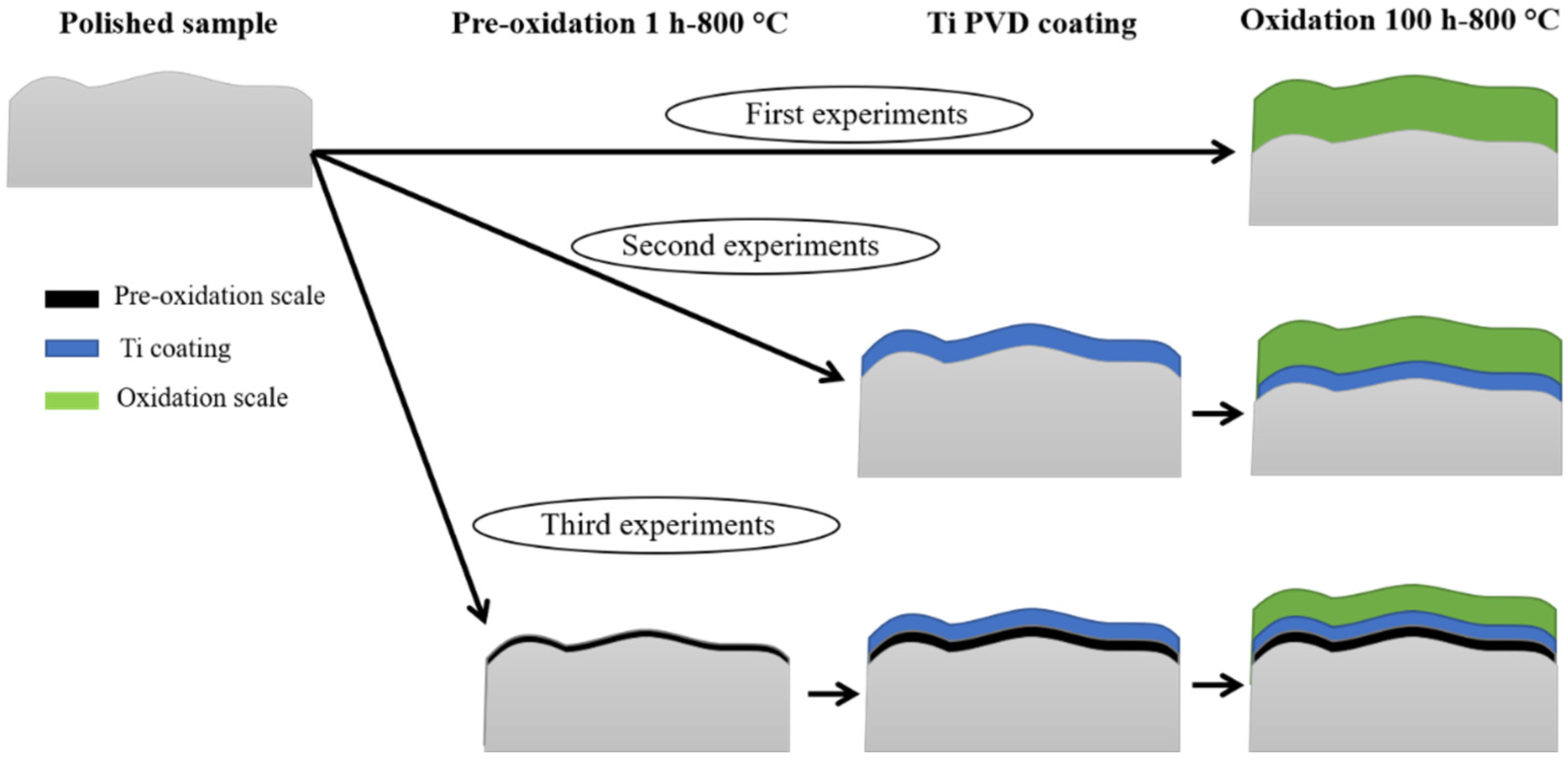
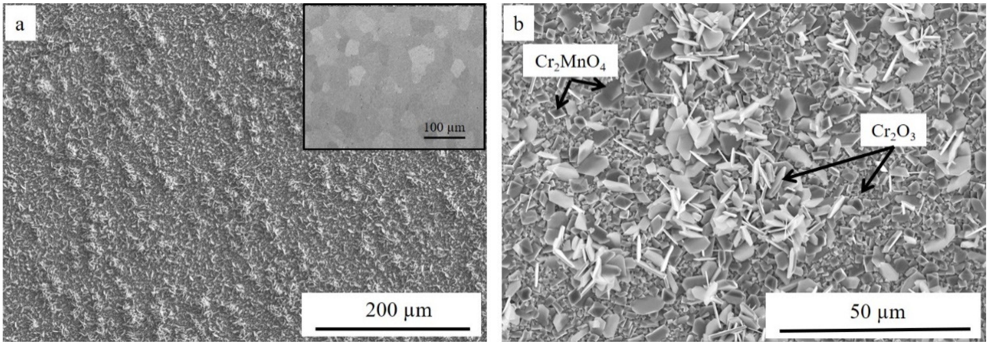
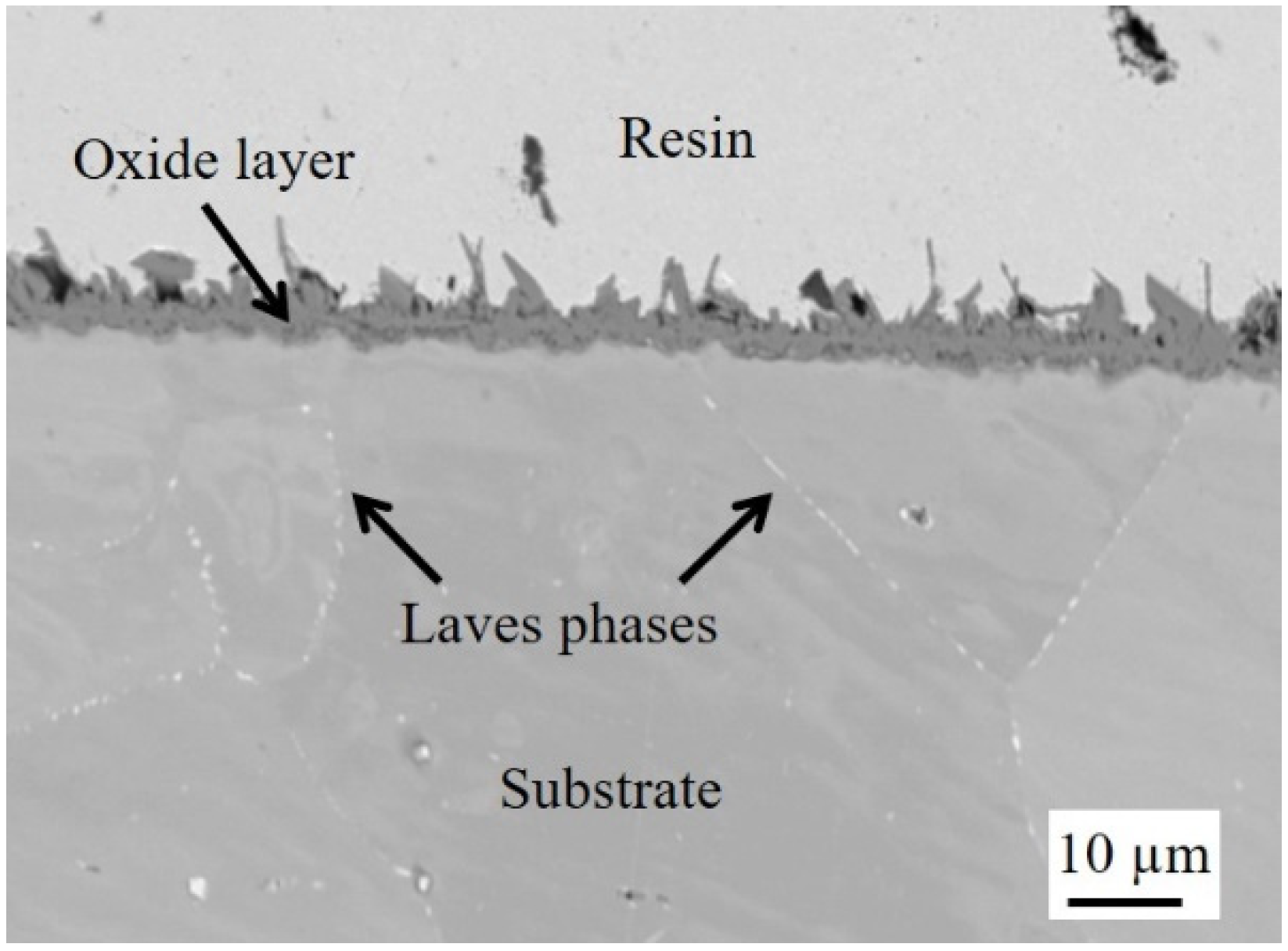
3.1. Oxidation of Polished Sample

Figure 2 shows the SEM micrographs of the surface of the polished sample after 100 h at 800 °C in ambient air. The mirror-polished surface before high-temperature oxidation is displayed in the inset of Figure 2a for comparison. The oxide scale was homogeneous with two kinds of crystals: big pyramidal grains and platelets covering a continuous lower layer formed by small grains. EDX analysis revealed that platelets and small grains were enriched in Cr, while pyramidal grains contained high amounts of Cr and Mn.
XRD analyses performed in Bragg–Brentano conditions (see Supplementary Material S1) confirmed the formation of chromia Cr2O3, corresponding to platelets and small grains covering the substrate, and a Cr2MnO4 spinel phase, corresponding to the pyramidal crystals. The substrate was also detected. This result is in agreement with the literature, where it has been reported that chromia and Cr-Mn spinel oxides are the typical phases that form at the surface of ferritic steels after aging at 800 °C under air [32,33,34]. As revealed by the backscattered image of the cross section of the oxidized sample, the thickness of the oxide layer ranged from about 4 to almost 8 µm considering the top of the platelets and the pyramidal grains (Figure 3). Laves phases enriched in Nb and Si decorated the grain boundaries [32].

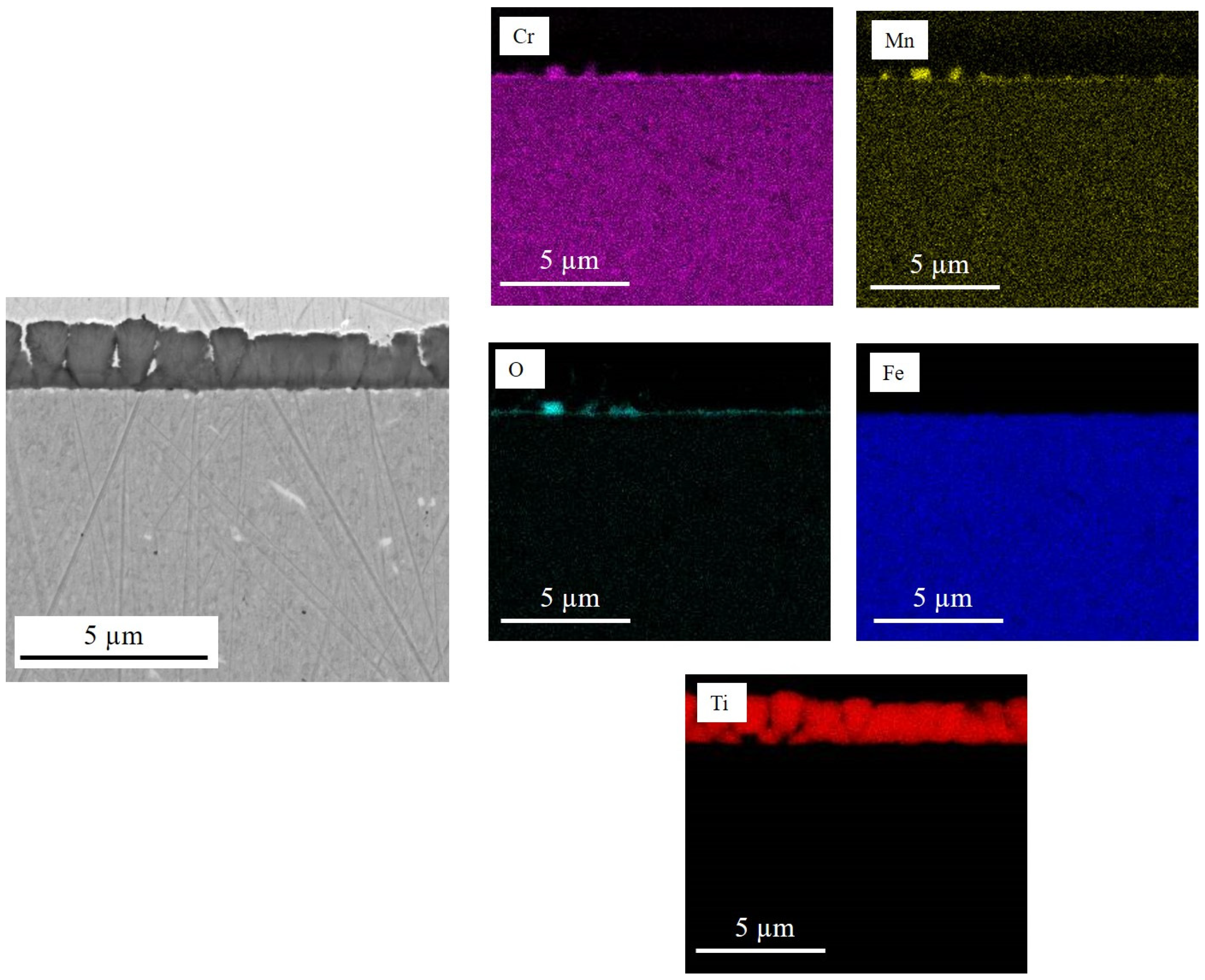
3.2. Oxidation of Ti-Coated Sample

The morphology of the as-deposited Ti PVD coating (surface and cross section) is presented in Figure 4.
The coating had a columnar-type structure (Figure 4a). The SEM cross section observation (Figure 4b.1) indicated that the coating was dense, well adherent to the substrate, and had a homogeneous thickness of about 1.2 µm. XRD analyses performed in Bragg–Brentano conditions (see Supplementary Material S2) confirm that the film was only composed of the hexagonal alpha Ti phase with a (002) texture. According to calculation using the Laue–Sherrer’s method, the coherent domain size was 16.5 ± 0.5 nm. EDX analyses revealed that the film was composed of Ti with an expected oxygen contamination of about 5 to 7 at.%. Figure 4b.2 shows the simulated film cross section (where gray is the film and brown is the substrate), which confirmed the SEM observations. The coating was dense and smooth and had a homogeneous thickness. Figure 4b.3 presents the coating porosity, where white represents the dense matter (film and substrate), yellow represents the air-connected pores (here, only the roughness), and blue represents the occluded pores. These pores were randomly distributed in the film and represented about 0.1% of the volume. The roughness of the bare substrate was about 13 nm, while the roughness after coating was slightly increased to 19 nm.
After 100 h of aging at 800 °C under ambient air, a significant surface spalling could be observed (Figure 5a).
EDX analyses (Figure 5b and Table 1) revealed that the spalled layer was the initial Ti coating transformed into TiO2 during aging (points 1 and 2). Points 3 and 4 corresponded to areas located beneath the TiO2 layer. These zones contained oxides formed by substrate elements and a particularly high amount of Si. Figure 5c shows a spalled TiO2 scale upside down. Some zones of wrenching could be observed. Inside this area, big grains with a morphology similar to Cr2O3 platelets formed at the surface of the uncoated sample after 100 h of oxidation at 800 °C (Figure 2b) could be distinguished and was confirmed by EDX characterizations (point 5). Finally, small grains surrounding the big Cr2O3 platelets presented a stoichiometry close to (Cr, Ti)2O3 (point 6). The lack of chromia platelets and spinel crystals at the surface of the steel was an indication that the spalling occurred at the end of the oxidation step or during the cooling.
The backscattered electron micrograph of the cross section taken in an area where the coating did not spall is displayed in Figure 6, together with the EDX elementary maps. The results confirmed the surface observations that a Cr2O3 layer had formed beneath TiO2. The thicknesses of both scales were almost the same of between 2 and 4 µm. As a comparison, in the case of the uncoated steel, Cr2O3 thickness ranged between 4 and 8 µm. On the other hand, the initial Ti coating was 1.2 µm thick, almost 2–3 times lower than the thickness measured for TiO2. This can be partially, but not only, explained by the presence of O atoms in the lattice, which were responsible for a volume expansion that led to an increased thickness when passing from metallic Ti to the oxide phase. A very small amount of Cr and Fe seemed to have diffused toward the external coating, likely forming a mixed Ti-Cr-Fe oxide between the Cr2O3 and TiO2 layers. Mn signal was slightly more pronounced inside the chromia layer, but elementary maps did not show evidence of the formation of Cr-Mn spinel oxides as in the case of the uncoated sample. Moreover, O and Si enrichment, likely SiO2, could be observed at the substrate/oxide scale interface as well as inside the substrate. The formation of this phase is thermodynamically possible as SiO2 is stable at low oxygen partial pressure (10−33 bar at 800 °C [24]). However, as reported by other authors [5], due to the non-miscibility between Cr2O3 and SiO2, spalling between these two phases can occur, especially during long-term oxidation.
These observations suggest that three zones could be distinguished inside the oxide scale (Figure 7): an inner Cr2O3 layer, an outer TiO2 oxide, and a transition zone between them, probably a mixed Cr-Fe-Ti oxide (Figure 7). It could be noticed that the TiO2 scale appeared quite dense, and some porosities were present at the interface between TiO2 and the mixed Cr-Fe-Ti oxide.
If it is assumed that TiO2 represents the starting interface, it is possible to claim that Cr2O3 is formed by inward oxygen diffusion and the mixed Cr-Fe-Ti by mixed inward oxygen and outward Cr-Fe diffusion through the Cr2O3 oxide layer.

3.3. Oxidation of Ti-Coated Sample after Pre-Oxidation

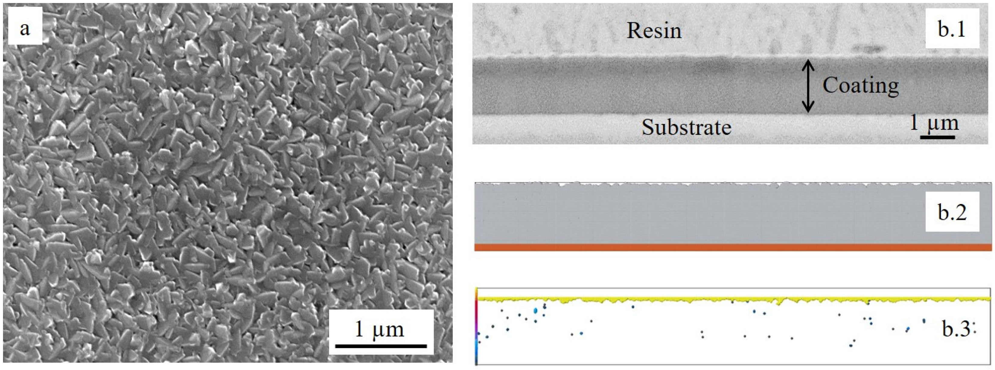
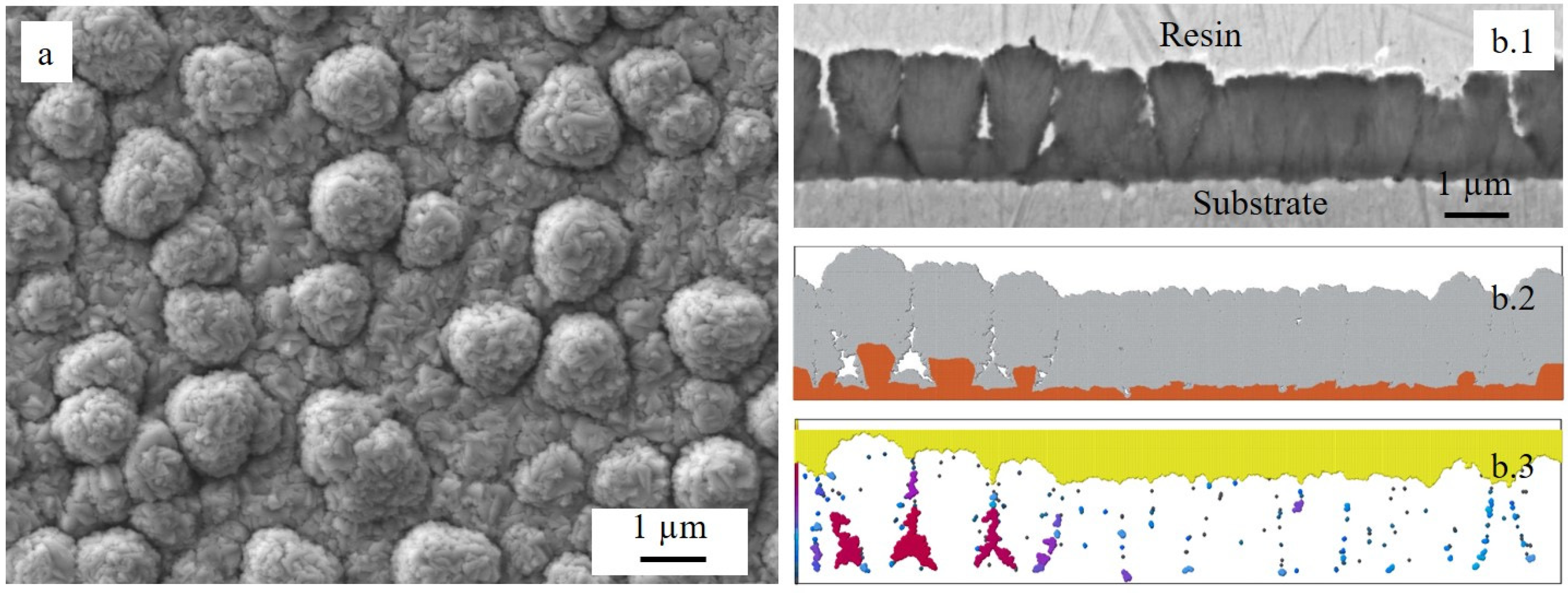
3.3.1. Ti Deposition after Pre-Oxidation

The polished steel substrate was pre-oxidized for 1 h at 800 °C in ambient air. Figure 8a shows that the surface was formed by a layer of small grains enriched in chromium and that big pyramidal crystals containing Cr and Mn, previously identified as Cr-Mn spinel oxides on the surface of the polished oxidized steel, were dispersed on the surface. The cross-sectional observation (Figure 8b) revealed that the oxide layer was very thin (a few hundred nm) and continuous. XRD performed at an incidence angle of 2° (Supplementary Material S3) confirmed that the oxide scale consisted of a chromium oxide Cr2O3. The Cr-Mn spinel phase was not detected. The crystals had quite a big size but were too dispersed.
Ti film was then deposited on the pre-oxidized steel substrate. The morphology of the coating (surface and cross section) is displayed in Figure 9.
The columnar-type structure was still present as observed without pre-oxidation. However, the surface was covered by a significant number of Ti nodules (Figure 9a). As reported in the literature [16], the morphology of the coating is directly influenced by the surface conditions of the substrate, notably roughness or irregularities, suggesting that the growth of Ti nodules was promoted by the presence of the Cr-Mn spinel oxide grains formed after 1 h of pre-oxidation at 800 °C. XRD and EDX analyses (texture, coherent domain size, and composition) presented exactly the same results as those for the film on the sample that was not pre-oxidized. The SEM cross-sectional micrography (Figure 9b.1) revealed that the coating was not fully dense over the total length due to the presence of the Ti nodules. Figure 9b.2 shows the simulated film cross section (gray is the film and brown is the substrate: steel and oxide together), which confirmed the SEM observations. The film nodules were due to the presence of the big oxide crystals. The discontinuities in the local topography induced shadowing and consequently voids in the film. Figure 9b.3 presents the coating porosity, where white represents the dense matter (film and substrate), yellow represents the air-connected pores (here, only the roughness), and blue to red represents the occluded pores (blue is for small pores and red is for big ones). These pores were vertically aligned and homogeneously distributed in the film. The porosity in this film represented about 3% of the volume, which was 30 times higher than that without substrate pre-oxidation. The roughness of the pre-oxidized substrate was about 118 nm, while the roughness after coating was slightly increased to 166 nm, which was the same proportion as for the substrate that was not pre-oxidized.
EDX elementary maps (Figure 10) confirmed that the average thickness of the Ti coating was 1.2 µm and showed evidence of the presence of a thin chromia layer and Cr-Mn spinel crystals between the substrate and the coating, which were formed during the pre-oxidation step.

3.3.2. Oxidation of Coated Pre-Oxidized Sample

The surface morphology of the pre-oxidized coated steel after 100 h of oxidation at 800 °C in ambient air is presented in Figure 11.
It is worth noting that spalling or cracking did not occur. The oxide scale was quite homogeneous, with big and rather spherical grains covering a lower layer formed by smaller grains. These big grains had the same distribution as the Cr-Mn spinel crystals formed after pre-oxidation (Figure 8a) and the Ti nodules formed after PVD deposition (Figure 9a). EDX analyses indicated that the scale was mainly composed of titanium oxide; a small amount of Cr was also detected. XRD performed at an incidence angle of 2° confirmed the formation of TiO2 as the majority phase, Ti5O9 (Magnéli phase), and the presence of a Cr-Mn spinel oxide (see Supplementary Material S4). Magnéli phases were substoichiometric Ti oxides of general formula TinO2n − 1 (n = 4–9) [35], which form for oxygen contents ranging between 60 and 66.67 at.% (corresponding to TiO2 formation) [36].
These results were confirmed by EDX elementary maps (Figure 12), showing the formation of titanium oxide and a duplex Cr2O3/(Cr,Mn)3O4 scale below.
The presence of SiO2 at the metal/oxide interface could also be observed. The thickness of the titanium oxide ranged between 1.2 and 3.3 µm considering the nodules. This value was lower than the one measured for the sample without pre-oxidation (between 2 and 4 µm). The thickness of the duplex Cr2O3/(Cr,Mn)3O4 layer varied from about 500 nm to 1.2 µm, i.e., more than 4 times lower than in the case of the steel that was not pre-oxidized. Several porosities were present inside the titanium oxide layer and at the TiO2/(Cr,Mn)3O4 interface. Their size and number were more important than in the case of the coated sample without pre-oxidation, in agreement with other works [16,37]. EDX maps revealed that a small amount of Cr diffused toward the external coating, but the diffusion of Fe was not observed. This was due to the Cr2O3 layer that was formed during pre-oxidation, which acted as a barrier and prevented the outward diffusion of Fe from the substrate. This phenomenon, in turn, promoted the formation of many pores inside the scale [16,37]. Concerning the reduction of the oxidation rate, some hypotheses can be suggested. During aging after pre-oxidation, the coating remained adherent to the Cr2O3 pre-formed scale, forming a barrier that limited potential oxygen diffusion. In parallel, to react with oxygen, Cr cations had to diffuse through the thermally grown Cr2O3 scale formed during pre-oxidation. Moreover, the formation of quite a continuous Cr-Mn spinel oxide layer above Cr2O3 (not evidenced after aging of the not coated steel that was not pre-oxidized) also acted as a barrier, thus reducing outward diffusion of Cr [38]. It should be noted that the formation of the (Cr,Mn)3O4 phase on top of the Cr2O3 layer was due to the higher diffusivity of Mn2+ in the Cr2O3 scale compared to Cr3+ (about 100 times higher) [39].

3.4. Discussion about Adhesion

The question that arises at this stage of the study relates to why the spalling of the oxide layer occurred in the case of the coated substrate that was not pre-oxidized.
The first consideration concerns the mechanical state of the substrate and the film before 100 h of oxidation. The film residual stress, obtained with the curvature method, was tensile and about 192 ± 40 MPa. As it was measured on a mirror-polished silicon substrate, it is assumed that this value also corresponds to the stress of the coating on the simply polished steel. As the coating on the pre-oxidized steel had about 3% of porosity, one can assume that the stress will be released. The substrate residual stress was determined for both samples (with and without pre-oxidation and after deposition) by X-ray diffraction using the sin²ψ method. In both cases, the stresses were compressive, but the values obtained for the coated sample that was not pre-oxidized (−542.5 ± 55.7 MPa) were about five times higher than those measured for the pre-oxidized one (−108.6 ± 50.6 MPa). These findings indicate the existence of an important difference in the mechanical state between the two substrates and the two films before undergoing high-temperature oxidation. If stress is generated during oxidation, the sample without pre-oxidation will have less ability to resist than the pre-oxidized one.
The second consideration is about the growth of the Cr2O3 scale underneath the TiO2 layer. This growth, which occurs during isothermal aging at high-temperature, generates growing stress. Indeed, the size of the Cr2O3 grains was much bigger than the TiO2 ones as revealed by SEM characterizations (Figure 5c). Once the coating cracks, the substrate is in direct contact with the oxidizing atmosphere, leading to an increase in the oxidation rate. This failure process is well known in the literature as mechanically induced chemical failure (MICF) [40].
The third consideration concerns the thermal stress, which occurs during cooling down and due to the differences between the thermal expansion coefficients (TEC) of the substrate and the different oxide scales. The TEC of the ferritic substrate tested in the present study was equal to 11–12 × 10−6 °C−1 between 100 and 800 °C, while the TEC of TiO2 was about 7–8 × 10⁻⁶ °C−1 between 25 and 1000 °C [41]. Cr2O3 has a TEC of 9.6 × 10⁻⁶ °C−1 between 25 and 1000 °C [41], which is an intermediate value between TiO2 and the ferritic substrate. It is possible to suggest that the presence of a continuous, albeit thin, Cr2O3 layer covering the substrate (Figure 8b) before the application of coating, i.e., from the first exposure instant of the Ti coating to the oxidant atmosphere, had a beneficial effect on the adhesion of the TiO2 scale forming during high-temperature exposure. Furthermore, the use of an appropriate interlayer between the PVD coating and the substrate has often been successfully reported in the literature to reduce the mismatch between the coating and the substrate and to limit the development of thermal stress during high-temperature exposure [42,43,44]. It is also noteworthy that in the case of the substrate that was not pre-oxidized, a thick and continuous SiO2 layer was detected. The main disadvantage of this oxide was its low TEC (0.5 × 10⁻⁶ °C−1) [41], which promoted spalling of the oxide scale.
In the present study, all these considerations play a role in the different behaviors observed for the two samples. To understand the mechanisms of scale spallation, in-situ SEM observations during oxidation are necessary.

4. Conclusions

In this study, a thin titanium layer (1.2 µm) was deposited on the surface of a ferritic stainless steel substrate by PVD technique before high-temperature exposure (100 h at 800 °C in ambient air). The effects of short pre-oxidation of the substrate (1 h at 800 °C) on the adhesion of the coating were investigated.
The major findings can be summarized as follows:
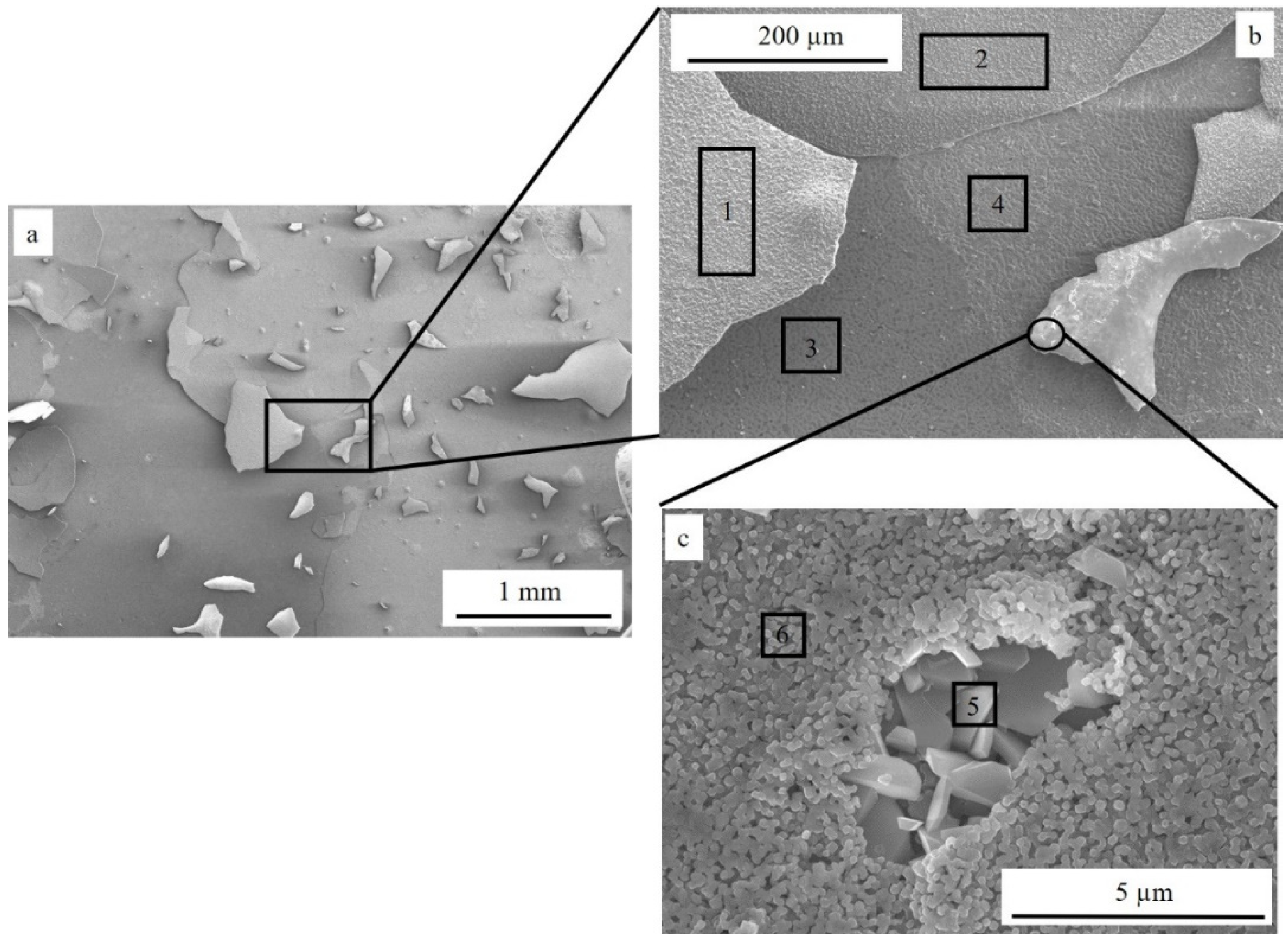
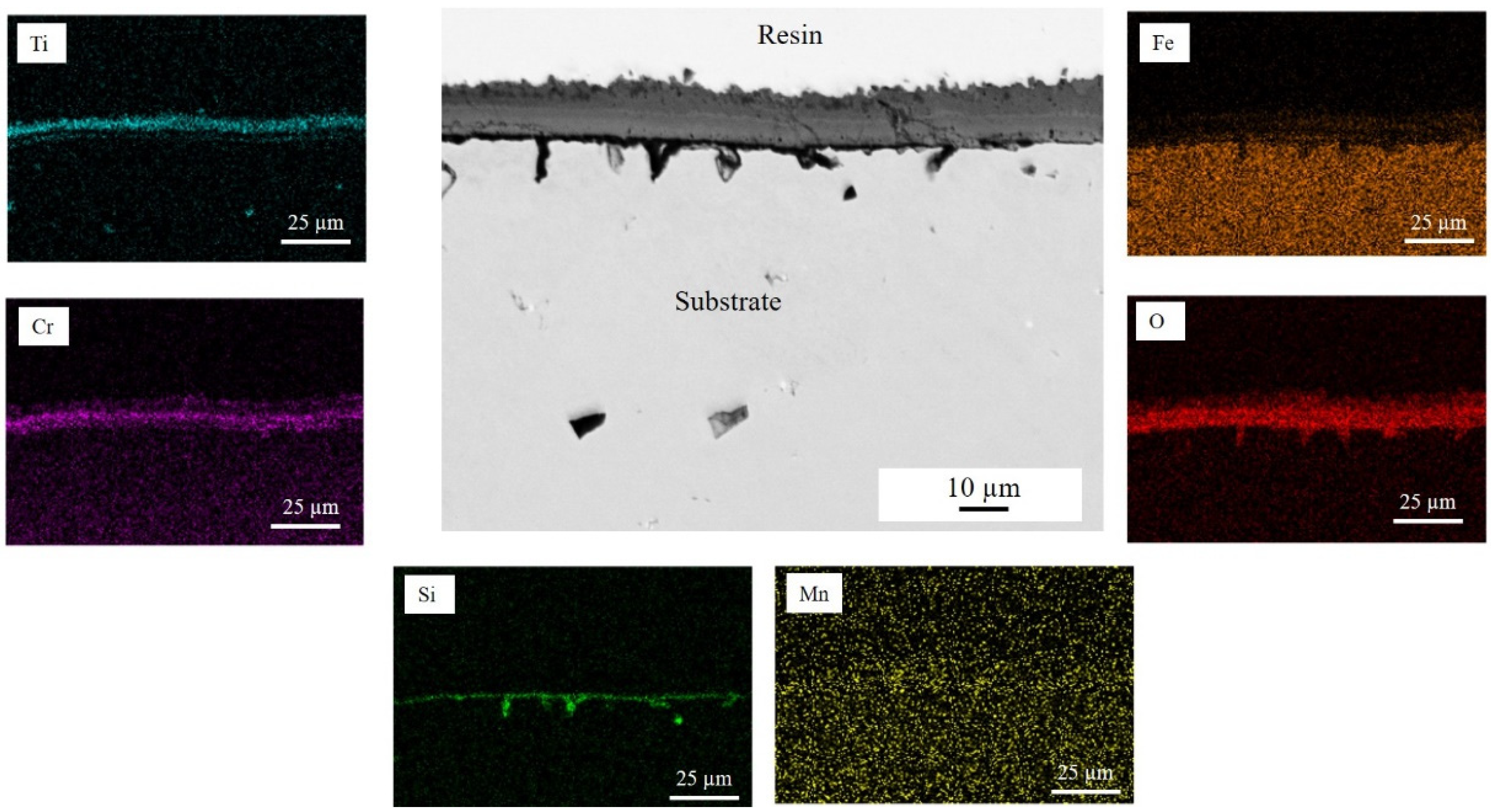
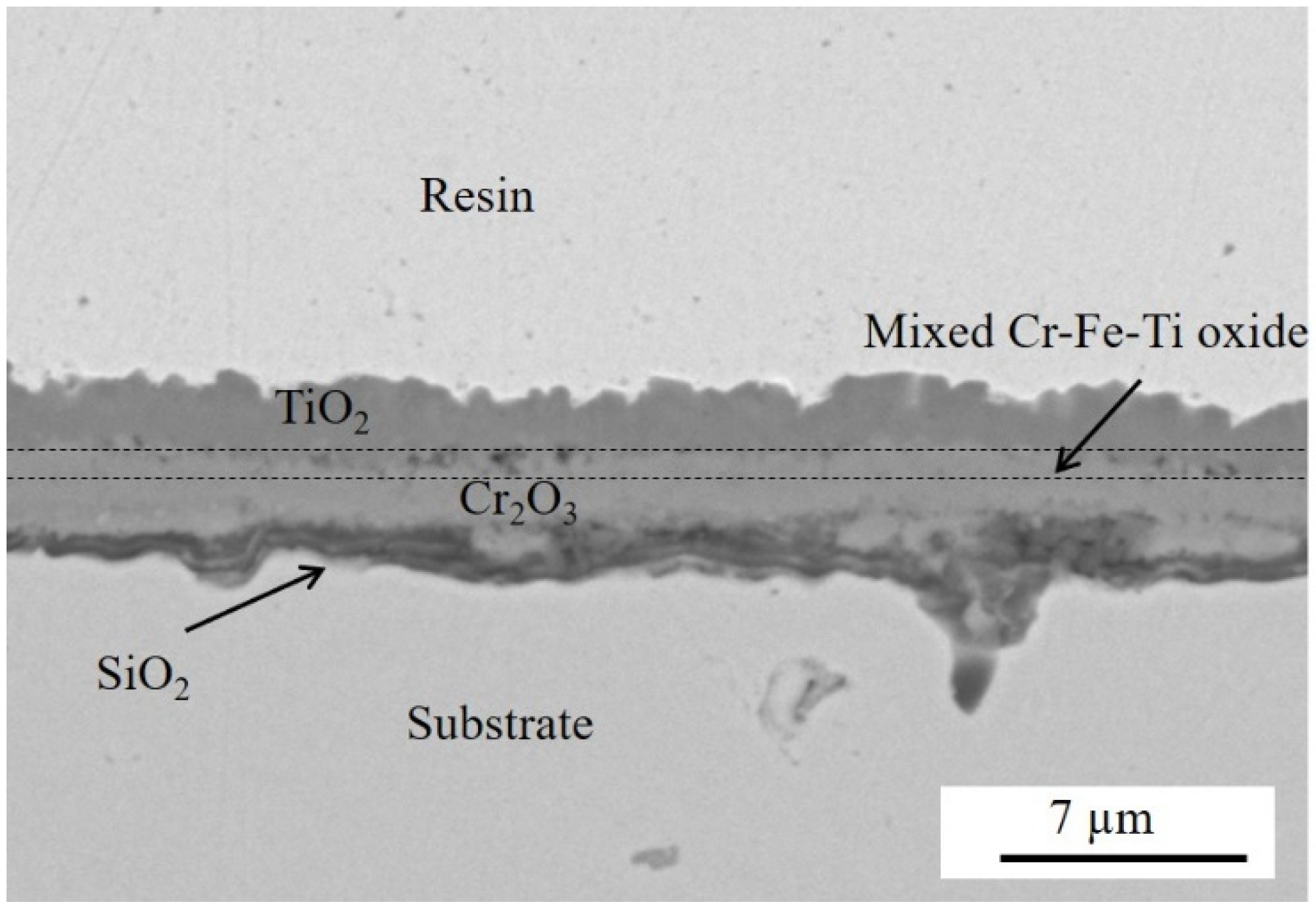
  • Metallic Ti converted into Ti oxide (TiO2) during high-temperature aging at 800 °C. TiO2 scale formed on the steel that was not pre-oxidized slowed down the oxidation of the substrate. Indeed, the thickness of the chromia layer ranged from about 4 to almost 8 µm in the case of the uncoated sample and between 2 and 4 µm for the sample that was not pre-oxidized. However, significant spallation of the TiO2 scale occurred during cooling down.
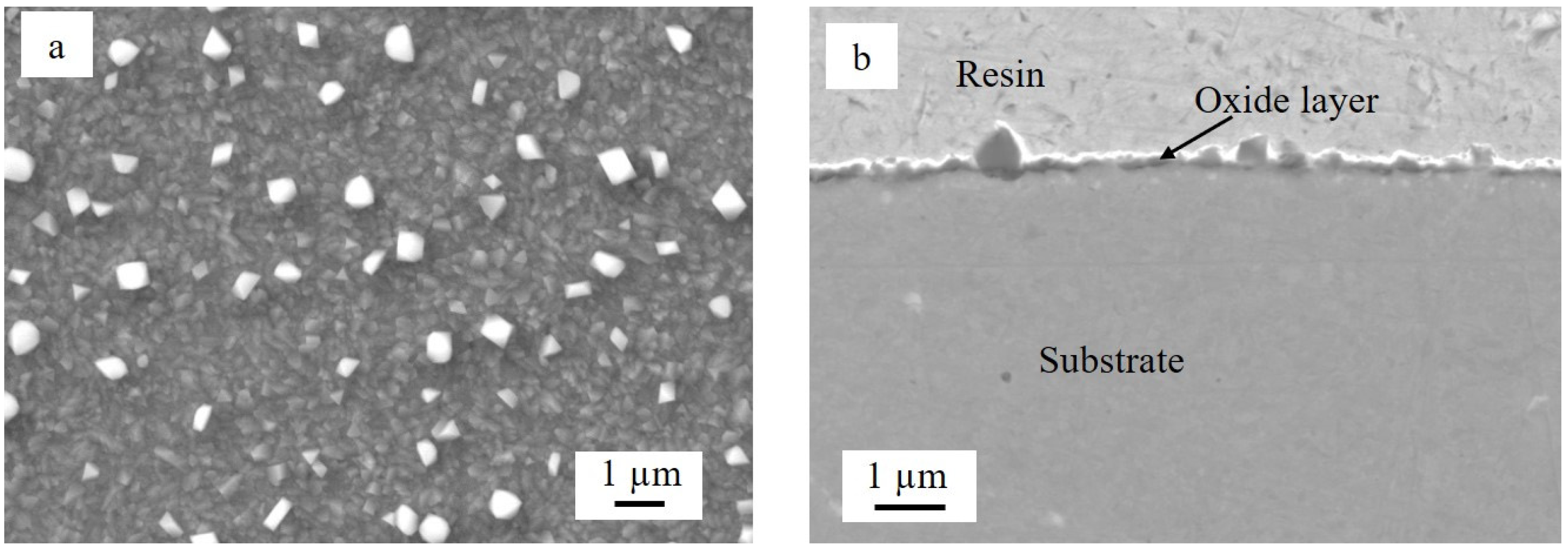
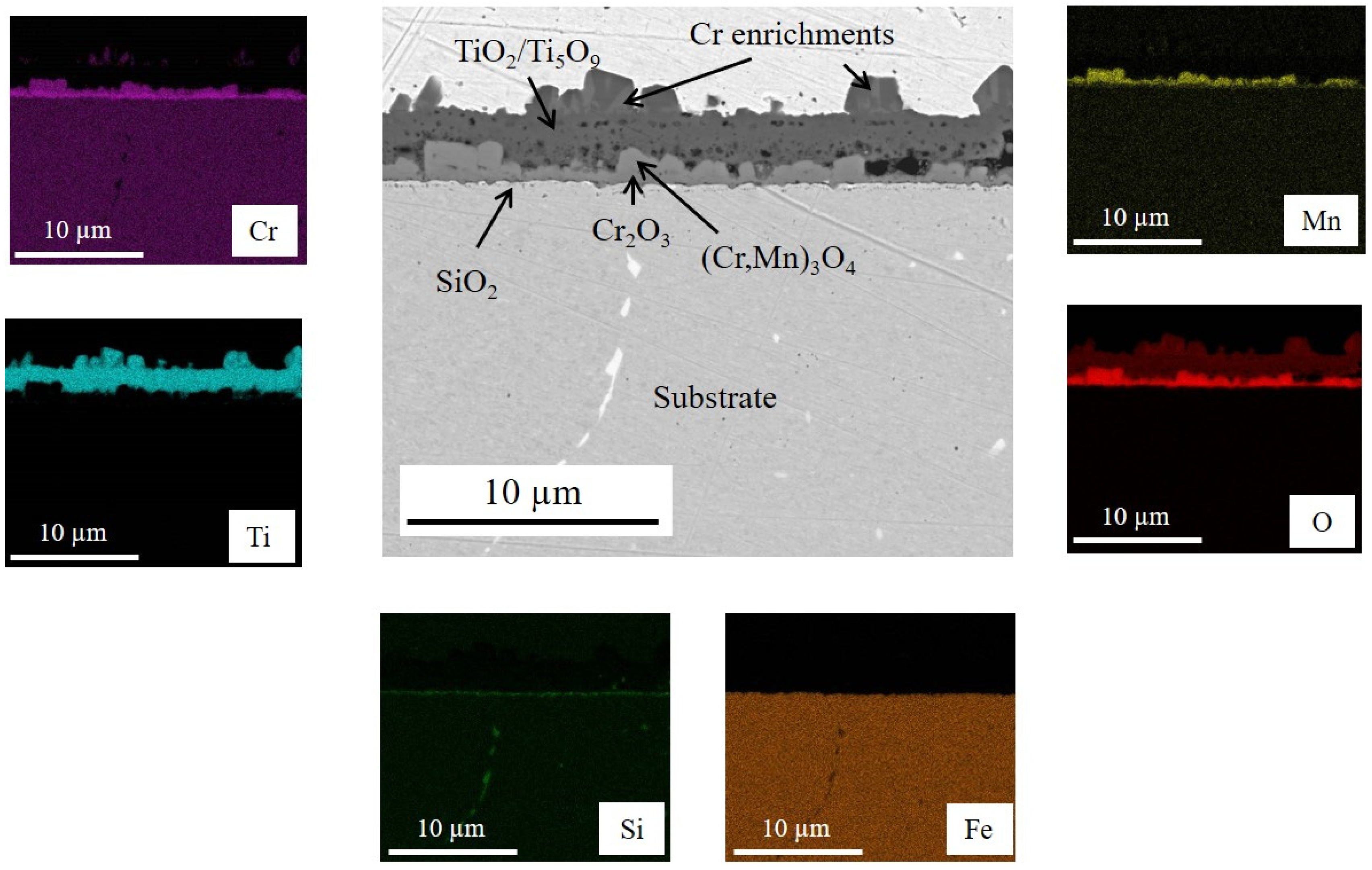
  • The TiO2 scale grown on the pre-oxidized steel effectively protected the substrate against oxidation. The thickness of the duplex Cr2O3/(Cr,Mn)3O4 layer varied from about 500 nm to 1.2 µm and was more than four times lower than in the case of the steel that was not pre-oxidized.
  • These different behaviors were the result of the combination of different kinds of stress, namely, residual, growing, and thermal stress.
  • The film residual stress on the polished substrate before 100 h of oxidation was tensile. On the other hand, the coating on the pre-oxidized steel had about 3% of porosity. This value was 30 times higher than the one measured in the case of the substrate that was not pre-oxidized. The substrate residual stress determined for both steel samples (with and without pre-oxidation) before undergoing high-temperature oxidation was compressive, but it was five times higher in the case of the steel that was not pre-oxidized (−542.5 ± 55.7 and −108.6 ± 50.6 MPa, respectively). If stress is generated during oxidation, the sample without pre-oxidation will have less ability to resist than the pre-oxidized one.
  • In the case of the substrate that was not pre-oxidized, the growing stress was due to the growth of the Cr2O3 scale underneath the TiO2 layer during isothermal oxidation, which led to the cracking of TiO2.
  • The thermal stress occurred during cooling down and was due to differences between the thermal expansion coefficients (TEC) of the substrate and the different oxide scales. Cr2O3 has a TEC intermediate between TiO2 and the ferritic steel substrate. In the case of the pre-oxidized steel, the presence of a continuous, albeit thin, Cr2O3 layer covering the substrate before the application of the coating, i.e., from the first exposure instant of the Ti coating to the oxidant atmosphere, had a beneficial effect on the adhesion of the TiO2 scale forming during high-temperature exposure.
To better understand the mechanism of the TiO2 scale spallation and to provide further responses, in-situ SEM-EDX characterizations are necessary to observe what occurs during isothermal oxidation.

Supplementary Materials

The following supporting information can be downloaded at: https://www.mdpi.com/article/10.3390/cryst12121732/s1. Figure S1: XRD patterns (Bragg-Brentano conditions) of the ferritic steel oxidized for 100 h at 800 °C in ambient air. Figure S2: XRD patterns (Bragg-Brentano conditions) of the Ti coating on Si substrate; Figure S3: XRD patterns (incidence angle of 2°) of the ferritic steel oxidized for 1 h at 800 °C in ambient air. Figure S4: XRD patterns (incidence angle of 2°) of the ferritic steel pre-oxidized for 1 h at 800 °C in ambient air, coated with Ti and then oxidized for 100 h at 800 °C in ambient air.

Author Contributions

Conceptualization, M.-R.A.-B. and A.B.; methodology, M.-R.A.-B., A.B. and G.N.B.; validation, M.-R.A.-B., A.B. and G.N.B.; investigation, M.-R.A.-B., A.B., Q.O., Y.P. and P.B.; writing—original draft preparation, M.-R.A.-B.; writing—review and editing, M.-R.A.-B., A.B. and G.N.B.; visualization, M.-R.A.-B.; supervision, M.-R.A.-B.; project administration, M.-R.A.-B. and A.B. All authors have read and agreed to the published version of the manuscript.

Funding

This research received no external funding.

Institutional Review Board Statement

Not applicable.

Conflicts of Interest

The authors declare no conflict of interest.

References

  1. Ardigo-Besnard, M.R.; Popa, I.; Chevalier, S. Spinel and perovskite coatings effect on long term oxidation of a ferritic stainless steel in H2/H2O atmosphere. Corros. Sci. 2019, 148, 251–263. [Google Scholar] [CrossRef]
  2. Ardigo, M.R.; Popa, I.; Chevalier, S.; Girardon, P.; Perry, F.; Laucournet, R.; Brevet, A.; Desgranges, C. Effect of coatings on long term behaviour of a commercial stainless steel for solid oxide electrolyser cell interconnect application in H2/H2O atmosphere. Int. J. Hydrogen Energy 2014, 39, 21673–21677. [Google Scholar] [CrossRef]
  3. Ardigo, M.R.; Popa, I.; Chevalier, S.; Parry, V.; Galerie, A.; Girardon, P.; Perry, F.; Laucournet, R.; Brevet, A.; Rigal, E. Coated interconnects development for high temperature water vapour electrolysis: Study in anode atmosphere. Int. J. Hydrogen Energy 2013, 38, 15910–15916. [Google Scholar] [CrossRef]
  4. Petric, A.; Ling, H. Electrical conductivity and thermal expansion of spinels at elevated temperatures. J. Am. Ceram. Soc. 2007, 90, 1515–1520. [Google Scholar] [CrossRef]
  5. Shaigan, N.; Qu, W.; Ivey, D.G.; Chen, W. A review of recent progress in coatings, surface modifications and alloy developments for solid oxide fuel cell ferritic stainless steel interconnects. J. Power Sources 2010, 195, 1529–1542. [Google Scholar] [CrossRef]
  6. Mardare, C.C.; Asteman, H.; Spiegel, M.; Savan, A.; Ludwig, A. Investigation of thermally oxidised Mn–Co thin films for application in SOFC metallic interconnects. Appl. Surf. Sci. 2008, 255, 1850–1859. [Google Scholar] [CrossRef]
  7. Yoon, J.S.; Lee, J.; Hwang, H.J.; Whang, C.M.; Moon, J.M.; Kim, D.H. Lanthanum oxide-coated stainless steel for bipolar plates in solid oxide fuel cells (SOFCs). J. Power Sources 2008, 181, 281–286. [Google Scholar] [CrossRef]
  8. Cabouro, G.; Caboche, G.; Chevalier, S.; Piccardo, P. Opportunity of metallic interconnects for ITSOFC: Reactivity and electrical property. J. Power Sources 2006, 156, 39–44. [Google Scholar] [CrossRef]
  9. Lim, D.P.; Lim, D.S.; Oh, J.S.; Lyo, I.W. Influence of post-treatments on the contact resistance of plasma-sprayed La0.8Sr0.2MnO3 coating on SOFC metallic interconnector. Surf. Coat. Technol. 2005, 200, 1248–1251. [Google Scholar] [CrossRef]
  10. Wu, J.; Johnson, C.D.; Jiang, Y.; Gemmen, R.S.; Liu, X. Pulse plating of Mn–Co alloys for SOFC interconnect applications. Electrochim. Acta 2008, 54, 793–800. [Google Scholar] [CrossRef]
  11. Mikkelsen, L.; Chen, M.; Hendriksen, P.V.; Persson, A.; Pryds, N.; Rodrigo, K. Deposition of La0.8Sr0.2Cr0.97V0.03O3 and MnCr2O4 thin films on ferritic alloy for solid oxide fuel cell application. Surf. Coat. Technol. 2007, 202, 1262–1266. [Google Scholar] [CrossRef]
  12. Gorokhovsky, V.I.; Gannon, P.E.; Deibert, M.C.; Smith, R.J.; Kayani, A.; Kopczyk, M.; VanVorous, D.; Yang, Z.G.; Stevenson, J.W.; Visco, S.; et al. Deposition and Evaluation of Protective PVD Coatings on Ferritic Stainless Steel SOFC Interconnects. J. Electrochem. Soc. 2006, 153, A1886–A1893. [Google Scholar] [CrossRef]
  13. Hoyt, K.O.; Gannon, P.E.; White, P.; Tortop, R.; Ellingwood, B.J.; Khoshuei, H. Oxidation behavior of (Co,Mn)3O4 coatings on preoxidized stainless steel for solid oxide fuel cell interconnects. Int. J. Hydrogen Energy 2012, 37, 518–529. [Google Scholar] [CrossRef]
  14. Pan, Y.; Geng, S.; Chen, G.; Wang, F. Effect of pre-oxidation on surface scale microstructure and electrical property of Cu-Fe coated steel interconnect. Corros. Sci. 2020, 170, 108680. [Google Scholar] [CrossRef]
  15. Yang, P.; Liu, C.-K.; Wu, J.-Y.; Shong, W.-J.; Lee, R.-Y.; Sung, C.-C. Effects of pre-oxidation on the microstructural and electrical properties of La0.67Sr0.33MnO3-δ coated ferritic stainless steels. J. Power Sources 2012, 213, 63–68. [Google Scholar] [CrossRef]
  16. Zhao, Q.; Geng, S.; Chen, G.; Wang, F. Influence of preoxidation on high temperature behavior of NiFe2 coated SOFC interconnect steel. Int. J. Hydrogen Energy 2019, 44, 13744–13756. [Google Scholar] [CrossRef]
  17. Amendola, R.; Gannon, P.; Ellingwood, B.; Hoyt, K.; Piccardo, P.; Genocchio, P. Oxidation behavior of coated and preoxidized ferritic steel in single and dual atmosphere exposures at 800 °C. Surf. Coat. Technol. 2012, 206, 2173–2180. [Google Scholar] [CrossRef]
  18. Talic, B.; Molin, S.; Hendriksen, P.V.; Lein, H.L. Effect of pre-oxidation on the oxidation resistance of Crofer 22 APU. Corros. Sci. 2018, 138, 189–199. [Google Scholar]
  19. Goebel, C.; Alnegren, P.; Faust, R.; Svensson, J.-E.; Froitzheim, J. The effect of pre-oxidation parameters on the corrosion behavior of AISI 441 in dual atmosphere. Int. J. Hydrogen Energy 2018, 43, 14655–14674. [Google Scholar] [CrossRef]
  20. Evrard, M.; Besnard, A.; Lucas, S. Study of the influence of the pressure and rotational motion of 3D substrates processed by magnetron sputtering: A comparative study between Monte Carlo modelling and experiments. Surf. Coat. Tech. 2019, 378, 125070. [Google Scholar] [CrossRef]
  21. Kofstad, P. High Temperature Corrosion; Elsevier Applied Science: London, UK; Elsevier Applied Science: New York, NY, USA, 1988. [Google Scholar]
  22. Coddet, C.; Chaze, A.M.; Beranger, G. Measurements of the adhesion of thermal oxide film: Application to the oxidation of titanium. J. Mater. Sci. 1987, 22, 2969–2974. [Google Scholar] [CrossRef]
  23. Chaze, A.M.; Coddet, C. The role of nitrogen in the oxidation behavior of titanium and some binary alloys. J. Less Common Metals 1986, 124, 73–84. [Google Scholar] [CrossRef]
  24. Hasegawa, M. Chapter 3.3—Ellingham Diagram. In Treatise on Process Metallurgy Volume 1: Process Fundamentals; Seetharaman, S., McLean, A., Guthrie, R., Sridhar, S., Eds.; Elsevier Ldt.: Oxford, UK, 2014; pp. 507–516. [Google Scholar]
  25. Nakajima, H.; Koiv, M. Diffusion in Titanium. ISIJ Int. 1991, 31, 757–766. [Google Scholar] [CrossRef] [Green Version]
  26. Shapovalov, V.P.; Kurasov, A.N. Diffusion of titanium in iron. Metalloved. Termich. Obrab. Metall. 1975, 9, 71–73. [Google Scholar] [CrossRef]
  27. Noyan, I.C.; Cohen, J.B. Residual Stress, Measurement by Diffraction and Interpretation; Springer: Berlin/Heidelberg, Germany, 1987. [Google Scholar]
  28. Besnard, A.; Ardigo, M.R.; Imhoff, L.; Jacquet, P. Curvature radius measurement by optical profiler and determination of the residual stress in thin films. Appl. Surf. Sci. 2019, 487, 356–361. [Google Scholar] [CrossRef] [Green Version]
  29. Depla, D.; Leroy, W.P. Magnetron sputter deposition as visualized by Monte Carlo modeling. Thin Solid Films 2012, 520, 6337–6354. [Google Scholar] [CrossRef]
  30. Ziegler, J.F.; Biersack, J.P. The stopping and range of ions in matter. In Treatise Heavy-Ion Science; Bromley, D.A., Ed.; Springer: Boston, MA, USA, 1985; Volume 6, Astrophys. Chem. Condens. Matter; pp. 93–129. [Google Scholar]
  31. Moskovkin, P.; Lucas, S. Computer simulations of the early stage growth of Ge clusters at elevated temperatures, on patterned Si substrate using the kinetic Monte Carlo method. Thin Solids Film 2013, 536, 313–317. [Google Scholar] [CrossRef]
  32. Niewolak, L.; Young, D.J.; Hattendorf, H.; Singheiser, L.; Quadakkers, W.J. Mechanisms of oxide scale formation on ferritic steel in simulated low and high pO2 service environments of solid oxide fuel cells. Oxid. Met. 2014, 82, 123–143. [Google Scholar] [CrossRef]
  33. Fontana, S.; Amendola, R.; Chevalier, S.; Piccardo, P.; Caboche, G.; Viviani, M.; Molins, R.; Sennour, M. Metallic interconnects for SOFC: Characterisation of corrosion resistance and conductivity evaluation at operating temperature of differently coated alloys. J. Power Sources 2007, 171, 652–662. [Google Scholar] [CrossRef]
  34. Bednarz, M.; Molin, S.; Bobruk, M.; Stygar, M.; Długoń, E.; Sitarz, M.; Brylewski, T. High-temperature oxidation of the Crofer 22 H ferritic steel with Mn1.45Co1.45Fe0.1O4 and Mn1.5Co1.5O4 spinel coatings under thermal cycling conditions and its properties. Mater. Chem. Phys. 2019, 225, 227–238. [Google Scholar] [CrossRef]
  35. Arif, A.F.; Balgis, R.; Ogi, T.; Iskandar, F.; Kinoshita, A.; Nakamura, K.; Okuyama, K. Highly conductive nano-sized Magnéli phases titanium oxide (TiOx). Sci. Rep. 2017, 7, 3646. [Google Scholar] [CrossRef] [PubMed]
  36. Waldner, P.; Eriksson, G. Thermodynamic modelling of the system titanium-oxygen. Calphad 1999, 23, 189–218. [Google Scholar] [CrossRef]
  37. Geng, S.; Zhao, Q.; Li, Y.; Mu, J.; Chen, G.; Wang, F.; Zhu, S. Sputtered MnCu metallic coating on ferritic stainless steel for solid oxide fuel cell interconnects application. Int. J. Hydrogen Energy 2017, 42, 10298–10307. [Google Scholar] [CrossRef]
  38. Yang, Z.; Xia, G.G.; Singh, P.; Stevenson, J.W. Electrical contacts between cathodes and metallic interconnects in solid oxide fuel cells. J. Power Sources 2006, 155, 246–252. [Google Scholar] [CrossRef]
  39. Lobnig, R.E.; Schmidt, H.P.; Hennesen, K.; Grabke, H.G. Diffusion of cations in chromia layers grown on iron-base alloys. Oxid. Met. 1992, 37, 81–93. [Google Scholar] [CrossRef]
  40. Evans, H.E.; Donaldson, A.T.; Gilmour, T.C. Mechanisms of breakaway oxidation and application to a chromia-forming steel. Oxid. Met. 1999, 54, 379–402. [Google Scholar] [CrossRef]
  41. Zhu, W.Z.; Deevi, S.C. Development of interconnect materials for solid oxide fuel cells. Mater. Sci. Eng. 2003, A348, 227–243. [Google Scholar] [CrossRef]
  42. Li, S.; Xiao, L.; Liu, S.; Zhang, Y.; Xu, J.; Zhou, X.; Zhao, G.; Cai, Z.; Zhao, X. Ultra-high temperature oxidation resistance of a novel (Mo, Hf, W, Ti)Si2 ceramic coating with Nb interlayer on Ta substrate. J. Eur. Ceram. Soc. 2022, 42, 4866–4880. [Google Scholar] [CrossRef]
  43. Anton, R.; Hüning, S.; Laska, N.; Weber, M.; Schellert, S.; Gorr, B.; Christ, H.J.; Schulz, U. Graded PVD Mo-Si interlayer between Si coating and Mo-Si-B alloys: Investigation of oxidation behavior. Corros. Sci. 2021, 192, 109843. [Google Scholar] [CrossRef]
  44. Lima, C.R.C.; Cinca, N.; Guilemany, J.M. Study of the high temperature oxidation performance of Thermal Barrier Coatings with HVOF sprayed bond coat and incorporating a PVD ceramic interlayer. Ceram. Int. 2012, 38, 6423–6429. [Google Scholar] [CrossRef]
Figure 1. Schematic approach of the experimental study.
Crystals 12 01732 g001
Figure 2. Secondary electron images of the surface of the polished sample after 100 h aging at 800 °C under ambient air: (a) global view and (b) magnification. Inset in (a): global view of the mirror-polished surface before high-temperature oxidation.
Crystals 12 01732 g002
Figure 3. Backscattered electron image of the cross section of the polished sample after 100 h aging at 800 °C under laboratory air.
Crystals 12 01732 g003
Figure 4. Morphologies of the as-deposited Ti PVD coating: (a) surface and (b.1) cross section, (b.2) simulated film growth using NASCAM, and (b.3) porosity of the simulated film.
Crystals 12 01732 g004
Figure 5. Secondary electron images of the surface of the Ti-coated sample after 100 h aging at 800 °C under laboratory air: (a) global view, (b) magnification of a spalled zone, and (c) magnification of spalled TiO2 scale upside down.
Crystals 12 01732 g005
Figure 6. Backscattered electron image and EDX elementary maps of the cross section of the Ti-coated sample after 100 h aging at 800 °C under ambient air.
Crystals 12 01732 g006
Figure 7. Magnification of the oxide layer formed in the case of the Ti-coated sample after 100 h aging at 800 °C under laboratory air.
Crystals 12 01732 g007
Figure 8. Backscattered electron image of the steel substrate after 1 h of pre-oxidation at 800 °C in ambient air: (a) surface and (b) cross section.
Crystals 12 01732 g008
Figure 9. Morphology of the Ti PVD coating deposited on the pre-oxidized steel: (a) surface and (b.1) cross section, (b.2) simulated film growth using NASCAM, and (b.3) porosity of the simulated film.
Crystals 12 01732 g009
Figure 10. Backscattered electron image and EDX elementary maps of the cross section of the Ti coating deposited on the pre-oxidized steel.
Crystals 12 01732 g010
Figure 11. Secondary electron image of the surface of the polished sample after 100 h aging at 800 °C under laboratory air: (a) global view and (b) magnification.
Crystals 12 01732 g011
Figure 12. Backscattered electron image and EDX elementary maps of the cross section of the Ti-coated pre-oxidized sample after 100 h aging at 800 °C under laboratory air.
Crystals 12 01732 g012
Table 1. EDX results (at.%) of areas indicated in Figure 5b,c.
ElementOSiTiCrMnFeNb
Point 164.70.132.12.60.30.2-
Point 260.7-33.54.90.40.5-
Point 331.114.50.69.6-43.60.6
Point 427.16.50.517.40.548.0-
Point 561.3-1.635.1-2.0-
Point 658.90.57.325.3-1.86.2
Publisher’s Note: MDPI stays neutral with regard to jurisdictional claims in published maps and institutional affiliations.

