Abstract
Strain-controlled low cycle fatigue experiments were carried out on the TiAl alloy Ti-45Al-4Nb-1Mo-0.15B at 400 °C and 750 °C to reveal the cyclic mechanical behavior and failure mechanism. The TiAl alloy presents stable cyclic characteristics under fatigue loading at elevated temperatures. No obvious cyclic softening or cyclic hardening was manifested during experiments. The cyclic stress–strain relationship is well described by the Ramberg–Osgood equation. The fatigue lifetime at different temperatures has a log-linear relationship with the total strain ranges. The fracture morphology indicates the main fracture mode of fatigue specimens at 400 °C is a brittle fracture, while there is a ductile fracture at 750 °C. Meanwhile, the trans-lamellar fracture is dominant for the lamellar microstructure and the percentages of the inter-lamellar fracture decreases with the strain amplitude.
1. Introduction
TiAl alloy has been successfully used in low-pressure aero-engines due to the low density (~3.9 g·cm−3), high specific strength, excellent creep and oxidation resistances [1,2,3,4,5] such as GEnx engines and the GTF engines [6,7,8]. However, brittleness, low fracture toughness and high notch sensitivity at room temperature limits its further development [9]. To ensure the in-service safety of TiAl structures, the high-temperature fatigue behavior and failure mechanism of the TiAl alloy must be carefully evaluated and verified [10].
The difference in the composition of TiAl alloys could lead to differences in the microstructure, playing an important role in fatigue performances and failure mechanisms under variant temperatures and loading conditions [11,12,13,14,15]. Cui et al. [16,17] found that duplex γ-TiAl alloy could undergo the degradation of lamellar structures and the recrystallization of γ-phase grains under a thermal-mechanical fatigue loading, which exhibits thermal instability. This thermal instability can increase creep damage under in-phase (IP) conditions and reduce the low-temperature crack propagation resistance under out-of-phase (OP) conditions. Sakaguchi et al. [18] used two forged TiAl alloys containing the β-phase with nearly lamellar and triplex microstructures to study the temperature dependence of fatigue crack propagation behavior and confirmed that the toughness of the β-phase could increase the fatigue crack propagation resistance at high temperatures.
Xu et al. [19] used three-point bending tests to reveal the different fatigue fracture mechanisms between notched specimens and smooth specimens of high-Nb TiAl alloys with α2/γ lamellae and β-phase segregation as well. They found that brittle cleavage fractures mostly appeared along the lamellar facet for the notched specimens while trans-lamellar fractures appeared with plastic characteristics for the smooth specimens. Chlupova et al. [20] studied the effect of heat treatment on the variant -TiAl alloys and considered that the inter-lamellar spacing and the alloy composition are the key factors that affect the ultimate tensile stress, fracture plastic strain, and cyclic strength of the material. Furthermore, reducing the inter-lamellar spacing can increase the cumulative plastic strain under cyclic loading at either room temperature or high temperature. Chen et.al [21] explored the fatigue resistance of polysynthetic twinned (PST) TiAl single crystal under high temperature and found that the PST TiAl single crystal will acquire improved high-cycle properties by undergoing a general homogeneous deformation without cracks. Furthermore, Yan et.al [22] found a contrary novel phenomenon to previous studies on lamellar materials that the fracture toughness of type II is higher than that of type I in PST TiAl alloy with coherent boundaries. However, it is still an open issue on the effects of alloy compositions and microstructures on the fatigue properties of TiAl alloys, although enormous efforts are being carried out [12,15,18,20].
To support the application of TiAl alloys in low-pressure turbine blades of aero engines, herein fatigue tests were carried out at the typical in-service temperatures of 400 °C (temperature of blade slot) and 750 °C (airfoil temperature) to explore the high-temperature fatigue behavior and fatigue failure mechanism of the Ti-45Al-4Nb-1Mo-0.15B alloy, which provides a basis for the life prediction modeling and structural safety assessment of TiAl alloys.
2. Materials and Tests
2.1. Materials
In this study, the nominal composition of the test material is Ti-45Al-4Nb-1Mo-0.15B (at.%). The electrode was made of a titanium sponge, high-purity Al, AlNb, AlMo and TiB2. Then, a round rod blank with a diameter of 18 mm was cast by two self-consuming melting processes and one induction smelting process. To eliminate shrinkage defects inside the casting, hot isostatic pressing (HIP) treatment was carried out at 1250 °C and 150 MPa for 4 h, followed by stress-relieving annealing treatment at 850 °C for 8 h. Figure 1 shows the microstructure of TiAl alloys under the optical microscopy (OM) and energy dispersive spectrum under scanning electron microscope. It can be seen from Figure 1a,b that the TiAl alloy has a typical three-phase structure. Among them, the brighter white area is -phase rich in Mo, while the -phase is darker gray, and both are equiaxed grains. The α2 lamellar colony are interspersed with small amounts of white β-phase and grey γ phase. Due to the presence of the β-phase, the grain size of the equiaxed grains is generally less than 20 μm, and that of the α2 lamellar colony is between 20 and 50 μm. The EDS elemental maps in Figure 1c show a uniform distribution and relative content of each element in the various phase structures.
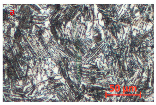
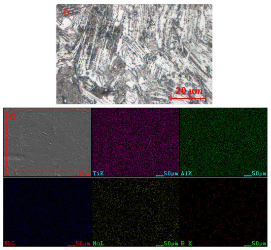
Figure 1.
OM (a) and magnified OM (b) images of microstructure and (c) Energy dispersive spectrum under scanning electron microscope of received TiAl alloy.
2.2. Test Procedure
The round rod specimens with a 15 mm gauge section were used in the test clamped by a thread connection, as shown in Figure 2a,b. Considering the room-temperature brittleness of the TiAl alloy, the thread was machined by grinding. Longitudinal polishing was used for the final processing of the gauge section to reduce the impact of scratches on the low-cycle fatigue performance of the material.
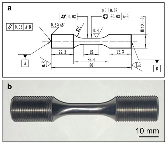
Figure 2.
The schematic illustration (a) and macrograph (b) of specimens for the strain-controlled fatigue test (unit: mm).
The fatigue test was carried out using an MTS Landmark Servo Hydraulic Test System. The TiAl alloy round rod specimens were clamped using an MTS680 hydraulic high-temperature grip. The test temperatures were set at 400 °C and 750 °C in a high-temperature furnace at atmospheric environment. After the specimen was clamped, the temperature was first raised to the test temperature for 30 min to ensure the specimen to be evenly heated. A triangular wave was used for the mechanical loading with a loading rate of 4 × 10⁻³ mm/s and the strain loading ratio . During the strain-controlled fatigue test, the temperature of the specimen was measured by a thermocouple fixed on the specimen by winding and binding, and the deformation behavior of the gauge section was measured by a high-temperature extensometer with a gauge length of 12 mm.
3. Results
3.1. Cyclic Stress–Strain Relationship
According to the strain-controlled fatigue test results, the engineering stress–strain response curves of the TiAl alloy under different strain amplitudes at 400 °C (Figure 3a) and 750 °C (Figure 3b) can be obtained. It can be seen that the width of the hysteresis loop gradually increased with increasing loading strain amplitude at the two temperatures, indicating that the cumulative damage of each cycle increased with the strain amplitude. Compared with the hysteresis loop under the same amplitude at 400 °C, the hysteresis loop at 750 °C is significantly wider, and the peak stress is lower. In addition, the specimen still exhibited a minor tension-compression asymmetry though the strain ratio during the test was −1, indicating that a small non-zero average stress was generated during the strain-controlled test.
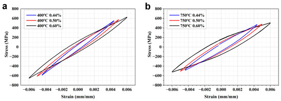
Figure 3.
Stable stress-strain curves of the TiAl alloy at (a) 400 °C and (b) 750 °C.
Figure 4 shows the peak stress curve of the TiAl alloy with the cycle number under variant experimental temperatures and strain amplitudes. At different temperatures, the peak stress did not change significantly with increasing cycle number, indicating that the TiAl alloy has relatively stable cycle characteristics under cyclic strain loading (no obvious cyclic softening or cyclic hardening). At a strain amplitude of 0.6%, the peak stresses of the material at 400 °C and 750 °C were approximately 620 MPa and 500 MPa, respectively, with a relatively larger difference. At the strain amplitude of 0.44%, both the peak stresses at the two temperatures were in the range of 450–500 MPa, with a small difference. In addition, the difference between the peak stresses corresponding to the two strain amplitudes at 400 °C was more significant than that at 750 °C. The above characteristics indicate that the plastic deformation characteristics of the TiAl alloy are sensitive to temperature, and the plasticity of the TiAl alloy is significantly enhanced at higher temperatures.
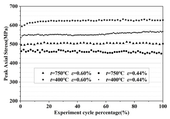
Figure 4.
Cyclic peak stress of the TiAl alloy at different temperatures.
The cyclic stress–strain response of the TiAl alloy can be described using the Ramberg–Osgood model, as follows
where K′ is the strength coefficient, n′ is the strain hardening index, and E is Young’s modulus at the corresponding temperature. The material constants of the Ramberg–Osgood model for the TiAl alloy at 400 °C and 750 °C can be obtained by fitting the test results using the stable cycles at different strain amplitudes, as shown in Table 1. Figure 5 indicates that the simulation results of the cyclic stress–strain relationship based on the Ramberg–Osgood model are consistent well with the experimental results. According to the Ramberg–Osgood model, the corresponding stresses of the TiAl alloy at 400 °C and 750 °C at 0.2% plastic strain are 580 MPa and 495 MPa, respectively, which indicates that as the temperature increases, the toughness of the TiAl alloy is improved, while the strength of the material is significantly reduced.
Δε/2 = σa/E + (σa/K′) 1/n′

Table 1.
Material constants of the Ramberg–Osgood model at different temperatures and

Figure 5.
Simulation results of the cyclic stress—strain relationship based on the Ramberg–Osgood model.
3.2. Fatigue Behavior
Figure 6a shows the lifetime results of the TiAl specimens at variant temperatures and strain amplitudes in the strain fatigue test. The strain–life curve of the TiAl alloy can be fitted using the Manson–Coffin model, as shown in Figure 6a. The Manson–Coffin model is as follows
where σf′ is the fatigue strength coefficient, b is the fatigue strength index, which represents the elastic fatigue characteristics of the material under a cyclic load, εf′ is the fatigue ductility coefficient, and c is the fatigue ductility index, which represents the cyclic plastic fatigue damage characteristics of the material. The material constants in the Manson–Coffin model at different temperatures obtained by the least square method are shown in Table 2. Figure 6a shows that under the same amplitude, the fatigue life decreased significantly with increasing temperature, reflecting a profound temperature sensitivity. Figure 6b shows the comparison between the predicted life based on the Manson–Coffin model and the test life under the strain-controlled fatigue loading for the TiAl alloy. Most of the fatigue life data points under different temperatures and loads lie within the scatter band factor of 2.
Δε/2 = (σf′/E)(2 Nf)b + εf′(2 Nf)c
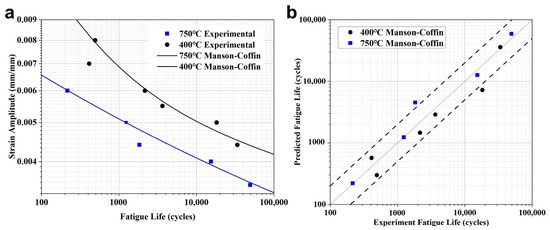
Figure 6.
Relationship between the low-cycle fatigue life and strain amplitude of the TiAl alloy (a) and the life prediction results by the Manson–Coffin model (b).
Table 2.
Material constants of the Manson–Coffin model.
4. Discussion
Figure 7 shows the macroscopic morphology of the fracture surface of the fatigue specimen under typical strain amplitudes ( = 0.44% and = 0.60%) at 750 °C and 400 °C. As shown in Figure 7a,c, it can be seen that the dimples in the typical fracture surface of the specimen at 750 °C are very significant and the proportion decreases with an increase in the strain amplitude. In the typical fracture surface of the specimen at 400 °C, however, the proportion of dimples is relatively low, and the size is relatively small, as shown in Figure 7b. The dimples could not even be observed under the amplitude of 0.6%, as shown in Figure 7d. The above fracture characteristics indicate that the ductility of the TiAl alloy decreases with decreasing temperature. It was also noticed that some scattered cracks generated in the fatigue specimens at both 400 °C with = 0.44% and 750 °C with = 0.60%, and this appearance is more prominent under the latter condition. Therefore, it can be deduced that no matter the temperature, there are some dissimilarities in the fracture mechanism of the specimen under = 0.60% and = 0.44%, and the difference will be more significant with decreasing the temperature.
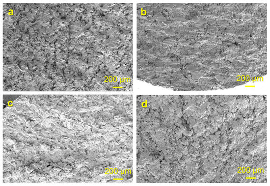
Figure 7.
Typical macroscopic morphology of the fracture surface of the TiAl specimen at (a) 750 °C, = 0.44%, (b) 400 °C, = 0.44%, (c) 750 °C,
= 0.60% and (d) 400 °C, = 0.60%.
Figure 8 shows magnified fracture morphology images of the specimens under variant strain amplitudes and temperatures. As shown in Figure 8a,b, the dimples appearing on the fractured surface of the specimen at 750 °C are relatively regular, the trans-granular fracture and the grain boundary separation of equiaxed grains increase with increasing strain amplitude, and grain boundary separation occurs between the lamellar colony and the equiaxed grains. Under a small strain amplitude, the inter-lamellar fracture around the dimple is more prominent, while under a high strain amplitude, the trans-lamellar fracture is more significant. These results indicate that the fracture surfaces exhibit significant ductile characteristics in the strain fatigue at 750 °C generally. However, as the strain amplitude increases significantly, the fracture mechanism demonstrates some dissimilarities, that is, the trans-granular fracture of equiaxed grains becomes more significant, and the inter-lamellar fracture changes to trans-lamellar fracture in the lamellar colony.
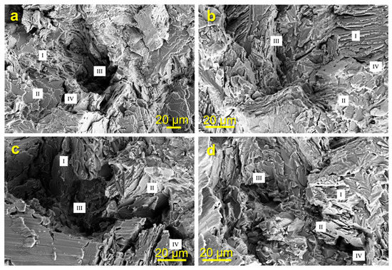
Figure 8.
Fracture morphologies of fatigue specimens at 750 °C with the strain amplitude (a) 0.44% and (b) 0.6% and at 400 °C with the strain amplitude (c) 0.44% and (d) 0.6%, where I denotes the translemallar fracture, II denotes the interlemallar fracture, III denotes the transgranular fracture, and IV denotes the intergranular fracture.
Figure 8c,d show the typical fracture surfaces of the fatigue specimens at 400 °C. The dimple becomes sharper and more irregular, grain boundary separation also occurs, and the trans-granular fracture of equiaxed grains becomes more significant with increasing strain amplitude. In the lamellar colony, the trans-lamellar fracture is dominant entirely. Under a small strain amplitude, the characteristics of inter-lamellar fracture are more obvious at the edge of the dimple. Under a high strain amplitude, the inter-lamellar fracture becomes occasionally visible, and inter-lamellar separation becomes obvious. All fracture morphologies of the strain-controlled fatigue specimens indicate that the fracture mechanism of the TiAl alloy has a high dependency on the temperature. The plasticity of the material at 750 °C is more significant, while the characteristics of brittle fracture are more prominent at 400 °C, which can reasonably explain the distinction in the cyclic mechanical behavior of the TiAl alloy at different temperatures. Furthermore, the fracture morphologies of fatigue specimens also demonstrate that the fracture mechanism of the TiAl alloy could be transformed with the load amplitude despite the temperature.
The contents of the main elements in the fracture of the fatigue specimens obtained through the energy dispersive spectrometry (EDS) technology at different temperatures are shown in Table 3 and Figure 9. It can be seen that the oxygen content on the fracture surface at 750 °C is almost double that at 400 °C. The lifetime of the selected specimens demonstrates that this difference in the degree of oxidation could not be due to time rather than the temperature characteristics of the TiAl material.
Table 3.
EDS results of the element contents on the fracture of specimens at different temperatures.
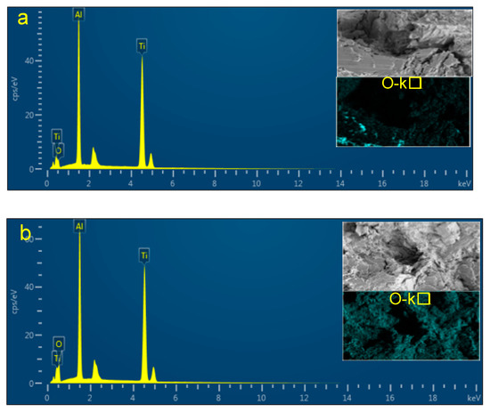
Figure 9.
Energy dispersive analysis of typical fracture surfaces (a) at 400 °C and (b) at 750 °C by EDS.
5. Conclusions
- (1)
- The Ti-45Al-4Nb-1Mo-0.15B alloy does not exhibit significant cyclic softening or cyclic hardening under strain cyclic loading at 400 °C and 750 °C and exhibits relatively stable cyclic characteristics, and its plasticity increase significantly with temperatures. The relationship between the strain fatigue life and the strain amplitude at different temperatures could be accurately represented by the Manson–Coffin model.
- (2)
- The Ti-45Al-4Nb-1Mo-0.5B alloy exhibits significant ductile fracture characteristics at 750 °C: the dimples on the fracture of the fatigue specimen are regular, trans-granular fractures are dominant in equiaxed grains, and there is an obvious separation between grain boundaries. As the strain amplitude increases, the inter-lamellar fracture decreases, while trans-lamellar fracture gradually becomes dominant in the lamellar colony, and the boundary separation between the lamellar colony and the equiaxed grains is more significant.
- (3)
- The Ti-45Al-4Nb-1Mo-0.5B alloy exhibits more obvious brittle fracture characteristics at 400 °C; the dimple on the fracture of the fatigue specimen becomes sharper and more irregular, trans-granular fractures are dominant in equiaxed grains, and trans-lamellar fractures are dominated in the lamellar colony. As the strain amplitude increases, the trans-granular fracture of the equiaxed grain becomes more obvious, and inter-lamellar fracture of the lamellar colony becomes occasionally visible. In addition, oxidation of the material is less obvious than that at 750 °C.
Author Contributions
Conceptualization, K.J., W.L. and J.C.; methodology, J.Y., K.J. and W.Z.; validation, K.J., W.L., J.C. and L.M.; investigation, W.Z. and J.Y.; data curation, W.Z. and J.Y.; writing—original draft preparation, K.J., W.Z. and J.Y.; writing—review and editing, J.Y. and W.Z.; supervision, J.Y. All authors have read and agreed to the published version of the manuscript.
Funding
This research was funded by Aviation Power Foundation (Grant No. 6141B090544) and the Natural Science Foundation of Hunan Province, China (Grant No. 2019JJ50702).
Institutional Review Board Statement
Not applicable.
Informed Consent Statement
Not applicable.
Data Availability Statement
Not applicable.
Acknowledgments
The authors gratefully acknowledge the financial support from the funding.
Conflicts of Interest
The authors declare no conflict of interest.
References
- Hodge, A.M.; Hsiung, L.M.; Nieh, T.G. Creep of nearly lamellar TiAl alloy containing W. Scr. Mater. 2004, 51, 411–415. [Google Scholar] [CrossRef]
- Zhang, S.; Zhang, C.; Du, Z.; Hou, Z.; Lin, P.; Chen, Y. Microstructure and tensile properties of hot fogred high Nb containing TiAl based alloy with initial near lamellar microstructure. Mater. Sci. Eng. A 2015, 642, 16–21. [Google Scholar] [CrossRef]
- Wen, Y.; Sun, J. Generalized planar fault energies and mechanical twinning in gamma TiAl alloys. Scr. Mater. 2013, 68, 759–762. [Google Scholar] [CrossRef]
- Kitashima, T.; Kawamura, T. Prediction of oxidation behavior of near-α titanium alloys. Scr. Mater. 2016, 124, 56–58. [Google Scholar] [CrossRef]
- Dong, C.; Yu, H.; Jiao, Z.; Kong, F.; Chen, Y. Low cycle fatigue, creep and creep-fatigue interaction behavior of a TiAl alloy at high temperatures. Scr. Mater. 2018, 144, 60–63. [Google Scholar] [CrossRef]
- Bartolotta, P.; Barrett, J.; Kelly, T.; Smashey, R. The use of cast Ti-48Al-2Cr-2Nb in jet engines. J. Mater. 1997, 49, 48–50. [Google Scholar] [CrossRef]
- Chen, G.; Peng, Y.B.; Zheng, G.; Qi, Z.; Wang, M.; Yu, H.; Dong, C.; Liu, C. Polysynthetic twinned TiAl single crystals for high-temperature applications. Nat. Mater. 2016, 15, 876–881. [Google Scholar] [CrossRef]
- Bewlay, B.; Nag, S.; Suzuki, A.; Weimer, M.J. TiAl alloys in commercial aircraft engines. Mater. High Temp. 2016, 33, 549–559. [Google Scholar] [CrossRef]
- Recina, V.; Lundstrm, D.; Karlsson, B. Tensile, creep, and low-cycle fatigue behavior of a cast γ-TiAl-based alloy for gas turbine applications. Metall. Mater. Trans. A 2002, 33, 2869–2881. [Google Scholar] [CrossRef]
- Zhang, Q.; Hua, X.; Zhang, Z.; Sun, T.; Wu, J.; Li, Y.; Ren, T. The mean stress and phase angle effect on multiaxial fatigue behavior of a TiAl alloy: Failure analysis and life modeling. Int. J. Mech. Sci. 2021, 193, 106123. [Google Scholar] [CrossRef]
- Werwer, M.; Kabir, R.; Cornec, A.; Schwalbe, K.H. Fracture in lamellar TiAl simulated with the cohesive model. Eng. Fract. Mech. 2007, 74, 2615–2638. [Google Scholar] [CrossRef]
- Li, M.; Xiao, S.; Xiao, L.; Xu, L.; Tian, J.; Chen, Y. Effects of carbon and boron addition on microstructure and mechanical properties of TiAl alloys. J. Alloy. Compd. 2017, 728, 206–221. [Google Scholar] [CrossRef]
- Loris, J.S.; Taiki, N.; Yotaro, O.; Ryosuke, Y.; Hirotoyo, N.; Masao, T. Fatigue crack growth behavior of wrought γ-based TiAl alloy containing β-phase. Intermetallics 2018, 100, 77–87. [Google Scholar]
- Li, Z.; Luo, L.; Su, Y.; Luo, L.; Wang, B.; Wang, L.; Yao, M.; Guo, J.; Fu, H. In-situ investigation of β/α transformation in β-solidifying γ-TiAl alloys at different cooling rates. Mater. Lett. 2021, 285, 129092. [Google Scholar] [CrossRef]
- Zhang, K.; Hu, R.; Lei, T.; Yang, J. Refinement of massive γ phase with enhanced properties in a Ta containing γ-TiAl-based alloys. Scr. Mater. 2019, 172, 113–118. [Google Scholar] [CrossRef]
- Cui, W.; Liu, C.; Bauer, V.; Christ, H.J. Thermomechanical fatigue behaviours of a third generation g-TiAl based alloy. Intermetallics 2007, 15, 675–678. [Google Scholar] [CrossRef]
- Bauer, V.; Christ, H.J. Thermomechanical fatigue behaviours of a third generation γ-TiAl intermetallic alloy. Intermetallics 2009, 17, 370–377. [Google Scholar] [CrossRef]
- Sakaguchi, M.; Niwa, Y.; Gong, W.; Suzuki, K.; Inoue, H. Temperature dependent fatigue crack growth in forged TiAl alloys with nearly-lamellar and triplex microstructure. Mater. Sci. Eng. A 2021, 806, 140802. [Google Scholar] [CrossRef]
- Xu, X.; Ding, H.; Li, W.; Huang, H.; Liang, H.; Kwak, S.; Chen, R.; Guo, J.; Fu, H. The smooth and notched three-point bending fatigue behavior of directionally solidified high-Nb TiAl alloy. Mater. Charact. 2021, 181, 111444. [Google Scholar] [CrossRef]
- Chlupova, A.; Heczko, M.; Obrtlík, K.; Dlouhý, A.; Kruml, T. Effect of heat-treatment on the microstructure and fatigue properties of lamellar γ-TiAl alloyed with Nb, Mo and/or C. Mater. Sci. Eng. A 2020, 786, 139427. [Google Scholar] [CrossRef]
- Chen, Y.; Cao, Y.; Qi, Z.; Chen, G. Increasing high-temperature fatigue resistance of polysynthetic twinned TiAl single crystal by plastic strain delocalization. J. Mater. Sci. Technol. 2021, 93, 53–59. [Google Scholar] [CrossRef]
- Yan, S.; Qi, Z.; Chen, Y.; Cao, Y.; Zhang, J.; Zheng, G.; Chen, F.; Bian, T.; Chen, G. Interlamellar boundaries govern cracking. Acta Mater. 2021, 215, 117091. [Google Scholar] [CrossRef]
Publisher’s Note: MDPI stays neutral with regard to jurisdictional claims in published maps and institutional affiliations. |
© 2022 by the authors. Licensee MDPI, Basel, Switzerland. This article is an open access article distributed under the terms and conditions of the Creative Commons Attribution (CC BY) license (https://creativecommons.org/licenses/by/4.0/).