Abstract
Control of solidification structure and crystallographic texture during metal additive manufacturing is a challenging work which attracts the increasing interest of researchers. In the present work, two kinds of scanning strategies (i.e., single-directional scanning (SDS) and cross-directional scanning (CDS) were used to control the solidification structure and crystallographic texture during quasi-continuous-wave laser additive manufacturing (QCW-LAM) of Inconel 718. The results show that the solidification structure and texture are strongly dependent on scanning strategies. The SDS develops a typical fiber texture with unidirectional columnar grains, whereas the CDS develops a more random texture with a mixture of unidirectional and multidirectional grains. In addition, the SDS promotes the continuously epitaxial growth of columnar dendrites and results in the linearly distributed Laves phase particles, while the CDS leads to the alternately distributed Laves phase particles with chain-like morphology and discrete morphology. The changed stacking features of molten-pool boundary and the switched heat flow direction caused by different scanning strategies plays a crucial role on the epitaxial growth of dendrites and the final solidification structure of the fabricated parts.
1. Introduction
Nickel-based superalloys are widely used in nuclear reactors, gas turbines, aero-engines and other high-temperature components due to their superior high-temperature mechanical properties and microstructural stability [1,2]. Laser additive manufacturing (LAM) has become more and more popular for fabricating or repairing of these components by a layer-by-layer fashion using metal powders [3,4,5]. LAM of nickel-based alloy generally utilizes a high-power laser, running in a continuous-wave (CW) mode (CW-LAM), to melt nickel-based powders onto a substrate to fabricate 3D components layer-by-layer. The mechanical properties of CW-LAM fabricated nickel-based superalloy are strongly dependent on the solidification structure and crystallographic texture. Therefore, it is crucial to control the microstructure and crystallographic texture for improving the mechanical properties of nickel-based superalloy.
Many works have been conducted to control the solidification structure and crystallographic texture of CW-LAM fabricated parts. These studies mainly include the change of laser processing parameters [6,7], the optimization of scanning strategies [2,8,9,10,11], the variation of substrate orientation [12,13], the forced cooling of the substrate [14,15], the electromagnetic oscillation [16], the change of laser input angles [17], etc. Among these studies, scanning strategy is considered to be an effective way to alter the molten-pool solidification conditions to achieve different grain structures and crystallographic texture. Liu et al. [8] found that single-directional scanning promotes the directional growth of columnar dendrites and the cross-directional scanning results in an increase in orientation deviation of dendrites. Both scanning strategies provide almost similar ultimate strength, while the cross-directional scanning exhibits higher ductility. Dinda et al. [2] found that a single-directional scanning produces a fiber texture with fine columnar grains, while a bidirectional scanning develops a rotated cube texture with coarse “zigzag” grains. Ishimoto et al. [10] reported that bidirectional scanning with and without a rotation of 90° between the layers result in different textures with preferential orientations of <001> and <011> and along the building direction, respectively. Sun et al. [11] found that single-crystalline-like texture can be produced via bidirectional scanning along one axis and bidirectional scanning with a 90° rotation in each layer, while only fiber texture was formed in bidirectional scanning with a 67° rotation. However, the control of grain structures and texture requires a good combination of scanning strategies and laser processing parameters. For example, under the same bidirectional scanning, a columnar grain structure with a strong <001> fiber texture was obtained at the high laser power, whereas a mixture of fine uniform and large columnar grains with a nearly random texture was achieved at the low laser power [18].
The solidification parameters, molten-pool geometry and orientation of dendrites in the substrate or the previous layer have been regarded as underlying factors in determining the formation of grain structures and crystallographic texture of LAM processed parts. Andreau et al. [19] found that the crystallographic texture strongly depends on the molten-pool geometry. The shallow conduction melt pool produces a strong {110}<001> Goss texture, while a deeper melt pool develops a weaker {110}<001> Goss texture in addition to a <100> fiber texture parallel to the scanning direction. Wang et al. [20] found that the solidification structure of LAM is also influenced by the substrate orientation. Liu et al. [21] found that the formation of stray grain is closely dependent on the substrate orientation and the molten-pool geometry. The desired microstructure can be obtained by a careful selection of process parameters to control the molten-pool geometry. Recently, researchers found that quasi-continuous-wave (QCW) LAM (QCW-LAM) was able to produce a smaller heat affected zone, a lower dilution ratio and a more refined grain structure than CW-LAM for a variety of materials, such as stainless steel [22], titanium alloy [23], aluminum alloy [24] and nickel alloy [4], due to the increased cooling rate of the molten pool. Our previous work [25] found that the QCW-LAM is featured by a high cooling rate, a periodic melting and solidification of the molten pool and a controllable molten-pool geometry. In addition, the QCW-LAM process refines microstructure and reduces element segregation of the fabricated parts [4]. As one of the most important processing variables of LAM, scanning strategy is crucial to modifiy molten-pool solidification condition and to control the microstructure of QCW-LAM. However, to the best of the author’s knowledge, effects of scanning strategy on the microstructure, crystallographic texture and mechanical property of QCW-LAM fabricated nickel-based superalloy are still unclear.
In the present work, two typical samples were fabricated by QCW-LAM with different scanning strategies. Role of scanning strategies on the solidification structure, crystallographic texture and mechanical property of LAM-fabricated Inconel 718 was evaluated. This work provides a method to control the microstructure and texture and also deepens the understanding of the microstructural formation in QCW-LAM.
2. Materials and Methods
In this work, the experiments were conducted on LAM system with coaxial powder feeding. The LAM system consists of a 4 KW laser, a coaxial powder nozzle, a six-axis robot and an atmosphere control system. Gas atomized Inconel 718 powders (Ni-19Cr-18Fe-5Nb-3Mo-1Ti-0.5Al) with the size of 45–150 μm were employed as the depositing materials. The 316L stainless steel plate was used as the substrate. Bulk samples were fabricated using QCW-LAM. During QCW-LAM, the laser was modulated by a square wave with laser pulse frequencies of 50 Hz, at a constant duty cycle of 50%. Other processing parameters include scanning speed of 6 mm s−1, laser beam diameter of 0.5 mm, powder feeding rate of 9.05 g min−1, overlapping ratio of 50% and delivering and shielding gas (Pure argon) of 8 L min−1. Two kinds of scanning strategies (i.e., single-directional scanning (SDS) and cross-directional scanning (CDS) were used, as shown in Figure 1. The temperature variation of the molten pool during QCW-LAM was measured using two two-color pyrometers. One pyrometer was fixed on the workbench to record the temperature variation at the center of the scanning path, and another moved with the laser beam focusing on the molten pool. The detailed set-up parameters can be found in our previous works [25].
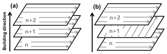
Figure 1.
Schematic diagrams showing two different scanning strategies used in the present work: (a) single-directional scanning (SDS) and (b) cross-directional scanning (CDS).
The metallographic samples were mechanically polished and then chemically etched with a solution of 100 mL H2O2, 100 mL HCl and 100 mL H2O for both optical micrograph (OM) observation and scanning electron microscopy (SEM) observation. Samples were also electrolytically polished with 10 vol% perchlorate alcohol solution at 20 V for 30 s for electron back scatter diffraction (EBSD) tests at an accelerating voltage of 20 kV and a step size of 1 μm.
3. Results and Discussion
3.1. Grain Structure and Solidification Texture
Figure 2 shows the optical micrographs of QCW-LAM fabricated samples with different scanning strategies. The SDS sample shows a typical layer-by-layer deposition pattern. In addition, there are many periodic discrete bands in each layer of the SDS sample (Figure 2a). These discrete bands represent the fusion zone boundaries formed in each laser pulse. The SDS sample is dominated by columnar dendrites which grow epitaxially from the previous layer. Most columnar dendrites can grow through many layers. The growth direction of columnar dendrites inclines to the laser scanning direction. The average primary dendrite arm spacing of the SDS sample is 4–5 μm (Figure 2b).
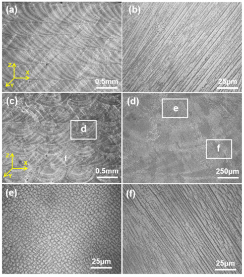
Figure 2.
Longitudinal cross-sectional optical micrographs of as-fabricated samples under different scanning strategies: (a,b) SDS and (c–f) CDS.
The CDS sample shows mixed grain morphologies (Figure 2c). The microstructure in the longitudinal section (parallel to the scanning direction) is dominated by columnar dendrites, which is similar with that of the SDS sample. The microstructure in the cross section (vertical to the scanning direction) is dominated by periodically arranged cell structure. Each cell structure consists of multidirectional equiaxed dendrites which grow from the molten-pool boundary toward the molten-pool center (Figure 2d). The average diameter of equiaxed dendrites is also 4–6 μm (Figure 2e) and the average primary dendrite arm spacing of columnar dendrites is 4–6 μm (Figure 2f).
In order to understand the orientated degree of grains, EBSD investigations were performed on the longitudinal cross-sections of the fabricated samples. Figure 3a,b shows the orientation image maps (OIM) of SDS and CDS samples, respectively. The EBSD maps are analogous to that of OM images in terms of orientation of grains. The SDS sample shows a highly oriented columnar grain structure. Most of grains are aligned in one direction (Figure 3a). The average width of columnar grain is 0.1 mm. Figure 3b shows the OIM of the CDS sample. A typical mixed grained morphology of highly orientated columnar grains and multi-directional grains alternated layer-by-layer are observed in the CDS sample. Note that the epitaxial growth between two adjacent layers is obviously disappeared and a more random grain structure is obtained.
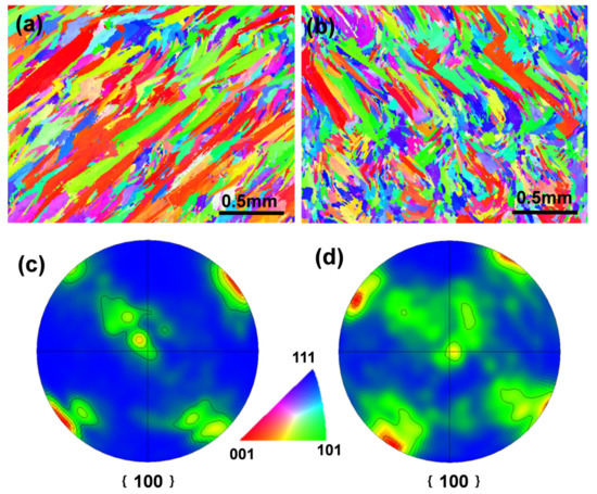
Figure 3.
Electron back scatter diffraction (EBSD) maps of as-fabricated samples: (a) Inverse pole figure (IPF) colored orientation image map (OIM) and (b) OIM map of CDS sample, (c) (100) pole figure of SDS sample and (d) (100) pole figure of CDS sample.
The (100) pole figures of longitudinal cross-sections of the SDS and CDS samples are shown in Figure 3c,d, respectively. It can be found that the SDS sample shows a typical fiber texture (Figure 3c), because only one of the <100> directions of columnar dendrites was oriented parallel to the heat flow direction. The (100) pole figure in Figure 3d shows the existence of a random cubic texture. The change of heat flow direction layer-by-layer caused by the CDS contributes to the alternately arranged grains and the formation of random texture in the CDS sample. In this situation, the continuously epitaxial growth is greatly suppressed.
According to the above results, we may conclude that the SDS develops unidirectional columnar grains with a typical fiber texture. The CDS produces a mixture of unidirectional and multidirectional grains with a random texture.
3.2. Dendrite Structure
Figure 4 shows the SEM micrographs of as-fabricated samples under different scanning strategies. In accordance with the results shown Figure 2a, the SDS sample is dominated by columnar dendrites (Figure 4a). Figure 4a shows the SEM morphology at the layer interface of the SDS sample. The directly epitaxial growth of columnar dendrites is promoted between two adjacent layers under SDS. Figure 4b shows the SEM morphology at the discrete band. The highly ordered columnar dendrites directly grow epitaxially over the curved discrete band in an identical layer. Figure 4c shows the layer-boundary microstructure of the CDS sample. Similar to the OM results (Figure 2c), the microstructure of the longitudinal section and the cross section is dominated by columnar morphology and equiaxed morphology, respectively (Figure 4c,d). These results show that the epitaxial growth between two adjacent layers is suppressed under CDS.
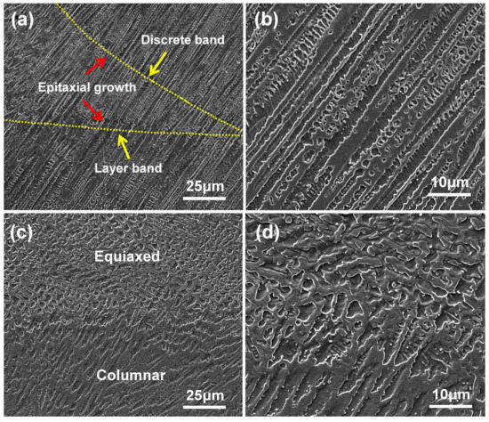
Figure 4.
Longitudinal cross-sectional SEM micrographs of as-fabricated samples under different scanning strategies: (a,b) SDS and (c,d) CDS.
3.3. Nb Segregation and Laves Phase Formation
Figure 5 shows the typical SEM morphologies of SDS and CDS samples after electrolytically polishing, respectively. The distribution of bright particles is related to the dendrite morphology. In the SDS sample, most of bright particles are interconnected (Figure 5a,b), showing a chain-like morphology. The bright particles in the longitudinal section of the CDS sample is linearly distributed at interdendritic regions (Figure 5c), which is similar with that of the SDS sample. Whereas the bright particles in the cross section of the CDS sample is featured by discrete morphology (Figure 5d).
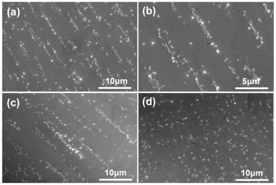
Figure 5.
SEM micrographs of samples after electrolytically polishing. (a,b) Particle morphology of the SDS sample; (c,d) particle morphology of two adjacent layers of the CDS sample.
Figure 6 shows the secondary electron micrograph and correspondingly elemental distributions of the SDS sample. The long-chain-like particles are rich in Nb and Mo atoms, and depleted in Cr and Fe atoms, whereas the core region of the dendrite is depleted in Nb and Mo atoms (Figure 6b–f). Such long-chain-like particles are commonly identified as Laves-phase according to its composition and morphology characteristics [26].
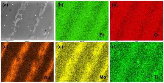
Figure 6.
The typical SEM micrographs (a) and elemental distributions of as-fabricated sample: Fe (b), Cr (c), Nb (d), Mo (e) and Ti (f).
3.4. Mechanical Property
Table 1 shows the mean ultimate tensile strength (UTS), yield strength (YS) and elongation (EL%) of samples. The UTS of the SDS sample and the CDS sample is 929.5 and 938.4 MPa, respectively. The UTS of as-fabricated samples is higher than that of the cast Inconel 718 (862 MPa) [27], but it is much lower than that of the wrought Inconel 718 (1276 MPa) [28]. The EL% of the SDS sample and the CDS sample is 18.3% and 24.8%, respectively, higher than that of the wrought Inconel 718 (12%). The as-deposited samples show low tensile strength and good ductility, attributed to the lack of γ″ hardening phase [29]. The rapid solidification of molten pool during LAM usually inhibits the formation of γ″ strengthening phase. Compared to the SDS sample, the CDS sample exhibits higher tensile strength and plasticity. The higher tensile properties of the CDS sample attributes to the more random and refiner grain structure and modified Laves phase morphology, and it will be discussed in Section 3.5.5.

Table 1.
Tensile properties of specimens under different processing conditions.
3.5. Solidification in QCW-LAM
3.5.1. Molten-Pool Thermal Behavior in QCW-LAM
Figure 7a shows the transient temperature variations of the molten pool during QCW-LAM. The transient temperature of the molten pool in QCW-LAM exhibits periodically oscillations due to the periodical laser energy input, which indicates the periodical melting and solidification of the molten pool. The temperature rapidly increases to the peak temperature of about 1920 °C as the laser switches on, and then rapidly cools to the minimum temperature of about 1415 °C. Note that the minimum molten-pool temperature (~1415 °C) of QCW-LAM is obviously higher than the melting point of Inconel 718 alloy (~1350 °C). It means that the molten pool is not completely frozen before the next laser pulse.
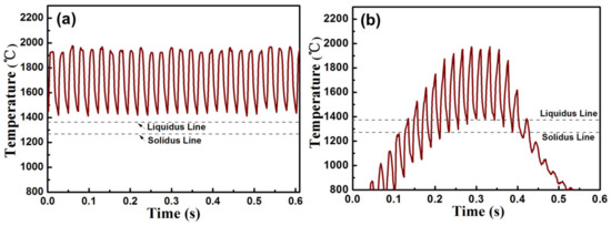
Figure 7.
Temperature variations of the molten pool during QCW-LAM: (a) Transient temperature curve and (b) fixed-point temperature curve.
Figure 7b shows the thermal variations of the fix point measured at the center of a path where the laser beam scans across during QCW-LAM. The measured point of the samples undergoes many thermal cycling treatments. The peak temperatures of the treatments increases with the approach of the laser beam and decreases as the laser beam away from. In order to understand the thermal behavior of the molten pool under different pulse frequency, the average cooling rate and solidification time of molten pool during solidification stage were calculated. The average cooling rate and the solidification time of the molten pool is 6.15 × 10³ °C/s and 13 ms, respectively.
3.5.2. Periodic Re-Melting of the Molten Pool in QCW-LAM
Compared with the unidirectional and quasi-steady state solidification mode in CW-LAM [25], the solidification in QCW-LAM is dynamic and more complex. Pulsed heat source modulation will result in periodic melting and solidification of the molten pool. The molten pool forms and expands as the moving laser beam radiates the substrate in laser-on stage. Then the molten pool rapidly cools and solidifies in laser-off stage. During QCW-LAM, the next pulse will re-melt partial of the solidified molten pool. The horizontal displacement of the molten pool is short in a single pulse period and the remained zone after re-melting is small. The remained zone is beneficial for the directional heat dissipation. In this situation, the continuously epitaxial growth of columnar dendrite in identical layers can be guaranteed, only if the columnar dendrite can grow at a relatively short and appropriate distance, because the re-melting of molten pool can eliminate the stray or mis-oriented grains formed far from molten-pool boundary or near molten-pool center. In addition, the highly directional columnar dendrite provides a highly good substrate orientation for the direct epitaxial growth of dendrites during next laser pulse.
3.5.3. Epitaxial Growth in QCW-LAM under Different Scanning Strategies
In the present work, different scanning strategies result in various solidification structure and crystallographic texture which attribute to the different molten-pool boundary and local heat flow direction. Figure 8 shows the schematic diagram of molten-pool boundary, heat dissipation and dendrite growth under different scanning strategies.
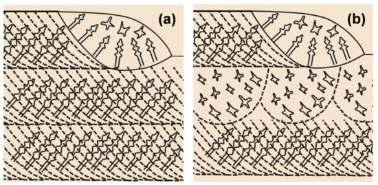
Figure 8.
Schematic diagrams showing microstructural formation in QCW-LAM under different processing conditions: (a) SDS and (b) CDS.
The SDS develops unidirectional columnar grains with a typical fiber texture. During QCW-LAM, a QCW laser irradiates the substrate and powder to form a molten pool. The melt pool dissipates heat into the substrate, creating a curved melt-pool boundary. The heat flow direction is substantially perpendicular to the molten pool boundary. During solidification of molten pool, columnar dendrite grows parallel to the opposite direction of heat flow and inclines to laser scanning direction. Under SDS condition, the scanning strategies between two adjacent layers are identical. The heat input and the heat dissipation mode (molten pool boundary and heat flow direction) of the current depositing layer are substantially consistent with the previous deposited layer, which is favorable for the directional growth of the dendrites (Figure 8a). As a result, a large number of columnar grains are formed and grow through many layers in the SDS sample.
The CDS develops a mixed morphology of alternating unidirectional columnar dendrites and multidirectional dendrites with a more random texture. In the case of QCW-LAM with a CDS, the laser beam scanning direction is normal to that of the previous deposited layer. For the first layer, the microstructure is dominated by directional columnar grains because the nucleation and dendrite growth mechanism is similar with that of SDS. However, in the next layer of deposition, the molten-pool boundary, the heat flow direction (the direction of the total temperature gradient) and the substrate orientation (or dendritic orientation in the deposited layer) of the molten pool are significantly changed, because of the change in the laser scanning direction. Thus, the dendrites, which grow preferably the previous deposited layer, will lose their growth superiority in the presented depositing layer, since their growth direction is largely deviated from the temperature gradient of the molten pool in the present depositing layer (Figure 8b). Thus, the columnar to equiaxed transition will occur in the present depositing layer, which depends on the deviation scale between the growth direction of the previous dendrites and the temperature gradient in the present depositing layer. Therefore, the second layer of the CDS sample is featured by periodic cell structure in which multidirectional and random dendrites are promoted. As a result, the CDS sample shows a mixed grained morphology of alternating unidirectional columnar dendrites and multidirectional dendrites.
3.5.4. Laves Phase Formation
Inconel 718 is a Nb-bearing nickel-based superalloy. During LAM, the non-equilibrium solidification of the highly localized molten pool results in micro segregations of high concentration refractory elements such as Nb, and eutectic Laves phases in LAM fabricated Inconel 718 alloy. Generally, the Nb segregation and the formation of Laves phase is highly undesirable as it reduces the mechanical properties of fabricated parts [30,31]. In addition, the chain-like Laves phase aids susceptibility to hot cracking. In the present work, the continuously distributed Laves phase was observed in the SDS sample, while the linearly distributed Laves phase is interrupted when the CDS is used. The changed morphology of Laves phase is considered to be related to the dendritic growth morphology [32] under two different scanning strategies. The continuously epitaxial growth of columnar dendrites in the SDS sample produces the linearly distributed interdendritic regions and finally results in the long-chain-like Laves phase. For the CDS sample, the continuously epitaxial growth of columnar dendrites was interrupted between two adjacent layers. In this situation, the alternating interdendritic regions of columnar and equiaxed morphology results in the chain-like and the discrete Laves phase particles at two adjacent layers, respectively.
3.5.5. Enhanced Tensile Property of CDS Sample
Compared with the SDS sample, the CDS sample shows better tensile properties, especially the high tensile ductility, which is due to the modified grain structure and Laves phase morphology. For the SDS sample, the highly-oriented coarse columnar grains and the long-chain-like Laves phase particles are obtained. The coarse columnar grains often results in the low tensile strength of the SDS sample. Moreover, the formation of coarsely long-chain-like Laves phase significantly reduces the tensile ductility and fracture toughness as it promotes the crack initiation and propagation [26]. In contrast, both UTS and EL are enhanced for CDS sample. On the one hand, the more random and finer grain structure with a mixture of columnar dendrites and equiaxed dendrites is beneficial for the enhancement of tensile properties. The continuously distributed Laves phase particles were broken under CDS, which is beneficial for the enhancement of tensile plasticity as it provides obstacles for crack propagation.
4. Conclusions
Inconel 718 samples were fabricated by QCW-LAM with different scanning strategies. Role of scanning strategies on solidification structure, crystallographic texture and mechanical property were evaluated. The following conclusions can be drawn:
- 1.
- The QCW-LAM is characterized by a periodic temperature variation, a periodic melting and solidification, a high cooling rate and a periodic re-melting of the molten pool due to the periodic energy input. The periodic remelting in QCW-LAM promotes the epitaxial growth of columnar dendrites.
- 2.
- The SDS develops unidirectional columnar grains with a typical fiber texture due to the continuously epitaxial growth of dendrites. But the CDS develops a mixture of unidirectional and multidirectional grains with a random texture owing to the change of heat flow direction between adjacent layers.
- 3.
- The Laves phase morphology is strongly dependent on the dendrite morphology. The SDS results in linearly distributed Laves phase particles, while the CDS produces the alternately distributed Laves phase particles of chain-like and discrete morphology.
- 4.
- The changed stacking features of molten-pool boundary and the switched heat flow direction caused by different scanning strategies play a crucial role on the epitaxial growth of dendrites and the final solidification structure of the fabricated parts.
- 5.
- Compared with the SDS sample, the CDS sample shows better tensile properties such as higher UTS and EL, than that of the SDS sample, due to the more random and finer grain structure and the modified Laves phase morphology.
Author Contributions
Conceptualization, X.L. and H.X.; methodology, H.X.; validation, X.L. and W.X.; formal analysis, W.X. and H.X.; investigation, L.S. and W.X.; resources, H.X. and L.S.; data curation, H.X.; writing—original draft preparation, X.L.; writing—review and editing, X.L., H.X. and L.S.; supervision, H.X.; project administration, L.S.; funding acquisition, H.X. and L.S. All authors have read and agreed to the published version of the manuscript.
Funding
This work was supported by the National Natural Science Foundation of China [No. 52001065; No. 51875190], the Guangdong Basic and Applied Basic Research Foundation [No. 2019A1515110274; No. 2021A1515010413], the Hunan Provincial Natural Science Foundation of China [No. 2020JJ5075].
Institutional Review Board Statement
Not applicable.
Informed Consent Statement
Not applicable.
Data Availability Statement
Not applicable.
Acknowledgments
We acknowledge Pan Xie for his help in data analysis.
Conflicts of Interest
The authors declare no conflict of interest.
References
- Amato, K.N.; Gaytan, S.M.; Murr, L.E.; Martinez, E.; Shindo, P.W.; Hernandez, J.; Collins, S.; Medina, F. Microstructures and mechanical behavior of Inconel 718 fabricated by selective laser melting. Acta Mater. 2012, 60, 2229–2239. [Google Scholar] [CrossRef]
- Dinda, G.P.; Dasgupta, A.K.; Mazumder, J. Texture control during laser deposition of nickel-based superalloy. Scr. Mater. 2012, 67, 503–506. [Google Scholar] [CrossRef]
- Debroy, T.; Wei, H.; Zuback, J.; Mukherjee, T.; Zhang, W. Additive manufacturing of metallic components—Process, structure and properties. Prog. Mater. Sci. 2018, 92, 112–224. [Google Scholar] [CrossRef]
- Xiao, H.; Xie, P.; Cheng, M.; Song, L. Enhancing mechanical properties of quasi-continuous-wave laser additive manufactured Inconel 718 through controlling the niobium-rich precipitates. Addit. Manuf. 2020, 34, 101278. [Google Scholar] [CrossRef]
- Xiao, H.; Cheng, M.; Song, L. Direct fabrication of single-crystal-like structure using quasi-continuous-wave laser additive manufacturing. J. Mater. Sci. Technol. 2021, 60, 216–221. [Google Scholar] [CrossRef]
- Chen, Y.; Zhang, K.; Huang, J.; Hosseini, S.R.E.; Li, Z. Characterization of heat affected zone liquation cracking in laser additive manufacturing of Inconel 718. Mater. Des. 2016, 90, 586–594. [Google Scholar] [CrossRef]
- Nie, P.; Ojo, O.A.; Li, Z. Modeling analysis of laser cladding of a nickel-based superalloy. Surf. Coat. Technol. 2014, 258, 1048–1059. [Google Scholar] [CrossRef]
- Liu, F.; Lin, X.; Huang, C.; Song, M.; Yang, G.; Chen, J.; Huang, W. The effect of laser scanning path on microstructures and mechanical properties of laser solid formed nickel-base superalloy Inconel 718. J. Alloys Compd. 2011, 509, 4505–4509. [Google Scholar] [CrossRef]
- Hagihara, K.; Nakano, T.; Suzuki, M.; Ishimoto, T.; Sun, S.H. Successful additive manufacturing of MoSi2 including crystallographic texture and shape control. J. Alloys Compd. 2017, 696, 67–72. [Google Scholar] [CrossRef]
- Ishimoto, T.; Hagihara, K.; Hisamoto, K.; Sun, S.H.; Nakano, T. Crystallographic texture control of beta-type Ti–15Mo–5Zr–3Al alloy by selective laser melting for the development of novel implants with a biocompatible low Young’s modulus. Scr. Mater. 2017, 132, 34–38. [Google Scholar] [CrossRef]
- Sun, S.H.; Hagihara, K.; Nakano, T. Effect of scanning strategy on texture formation in Ni-25at.%Mo alloys fabricated by selective laser melting. Mater. Des. 2018, 140, 307–316. [Google Scholar] [CrossRef]
- Liu, Z.; Qi, H. Effects of substrate crystallographic orientations on crystal growth and microstructure formation in laser powder deposition of nickel-based superalloy. Acta Mater. 2015, 87, 248–258. [Google Scholar] [CrossRef]
- Wang, L.; Wang, N. Effect of substrate orientation on the formation of equiaxed stray grains in laser surface remelted single crystal superalloys: Experimental investigation. Acta Mater. 2016, 104, 250–258. [Google Scholar] [CrossRef]
- Chen, Y.; Lu, F.; Zhang, K.; Nie, P.; Elmi Hosseini, S.R.; Feng, K.; Li, Z. Dendritic microstructure and hot cracking of laser additive manufactured Inconel 718 under improved base cooling. J. Alloys Compd. 2016, 670, 312–321. [Google Scholar] [CrossRef]
- Zhang, Y.C.; Li, Z.G.; Nie, P.L.; Wu, Y.X. Effect of ultrarapid cooling on microstructure of laser cladding IN718 coating. Surf. Eng. 2013, 29, 414–418. [Google Scholar] [CrossRef]
- Liu, F.; Cheng, H.; Yu, X.; Yang, G.; Jing, C. Control of microstructure and mechanical properties of laser solid formed Inconel 718 superalloy by electromagnetic stirring. Opt. Laser Technol. 2018, 99, S003039921730539X. [Google Scholar] [CrossRef]
- Chen, Y.; Lu, F.; Zhang, K.; Nie, P.; Elmi Hosseini, S.R.; Feng, K.; Li, Z.; Chu, P.K. Investigation of dendritic growth and liquation cracking in laser melting deposited Inconel 718 at different laser input angles. Mater. Des. 2016, 105, 133–141. [Google Scholar] [CrossRef]
- Parimi, L.L.; Clark, D.; Attallah, M.M. Microstructural and texture development in direct laser fabricated IN718. Mater. Charact. 2014, 89, 102–111. [Google Scholar] [CrossRef]
- Olivier, A.; Imade, K.; Patrice, P.; Jean-Daniel, P.; Nicolas, S.; Etienne, P.; Thibaut, D.T.; Corinne, D.; Thierry, B. Texture control of 316L parts by modulation of the melt pool morphology in selective laser melting. J. Mater. Process. Technol. 2019, 264, 21–31. [Google Scholar]
- Wang, L.; Wang, N.; Yao, W.J.; Zheng, Y.P. Effect of substrate orientation on the columnar-to-equiaxed transition in laser surface remelted single crystal superalloys. Acta Mater. 2015, 88, 283–292. [Google Scholar] [CrossRef]
- Liu, W.; Dupont, J.N. Effects of melt-pool geometry on crystal growth and microstructure development in laser surface-melted superalloy single crystals: Mathematical modeling of single-crystal growth in a melt pool (part I). Acta Mater. 2004, 52, 4833–4847. [Google Scholar] [CrossRef]
- Pinkerton, A.J.; Li, L. The effect of laser pulse width on multiple-layer 316L steel clad microstructure and surface finish. Appl. Surf. Sci. 2003, 208, 411–416. [Google Scholar] [CrossRef]
- Ravi, G.A.; Qiu, C.; Attallah, M.M. Microstructural control in a Ti-based alloy by changing laser processing mode and power during direct laser deposition. Mater. Lett. 2016, 179, 104–108. [Google Scholar] [CrossRef]
- Luo, G.; Xiao, H.; Li, S.; Wang, C.; Zhu, Q.; Song, L. Quasi-continuous-wave laser surface melting of aluminium alloy: Precipitate morphology, solute segregation and corrosion resistance. Corros. Sci. 2019, 152, 109–119. [Google Scholar] [CrossRef]
- Li, S.; Xiao, H.; Liu, K.; Xiao, W.; Li, Y.; Han, X.; Mazumder, J.; Song, L. Melt-pool motion, temperature variation and dendritic morphology of Inconel 718 during pulsed- and continuous-wave laser additive manufacturing: A comparative study. Mater. Des. 2017, 119, 351–360. [Google Scholar] [CrossRef]
- Xiao, H.; Li, S.; Han, X.; Mazumder, J.; Song, L. Laves phase control of Inconel 718 alloy using quasi-continuous-wave laser additive manufacturing. Mater. Des. 2017, 122, 330–339. [Google Scholar] [CrossRef]
- SAE Aerospace. Aerospace Material Specification: AMS5383; SAE International: Warrendale, PA, USA, 2009. [Google Scholar]
- SAE Aerospace. Aerospace Material Specification: AMS 5662; SAE International: Warrendale, PA, USA, 2012. [Google Scholar]
- Qi, H.; Azer, M.; Ritter, A. Studies of Standard Heat Treatment Effects on Microstructure and Mechanical Properties of Laser Net Shape Manufactured INCONEL 718. Metall. Mater. Trans. A 2009, 40, 2410–2422. [Google Scholar] [CrossRef]
- Janaki Ram, G.D.; Venugopal Reddy, A.; Prasad Rao, K.; Madhusudhan Reddy, G. Control of Laves phase in Inconel 718 GTA welds with current pulsing. Sci. Technol. Weld. Join. 2004, 9, 390–398. [Google Scholar] [CrossRef]
- Shang, S.; Jing, C.; Fan, E.; Yang, H.; Xin, L.; Huang, W. The influence of Laves phases on the high-cycle fatigue behavior of laser additive manufactured Inconel 718. Mater. Sci. Eng. A 2017, 695, 6–13. [Google Scholar]
- Ling, L.; Han, Y.; Zhou, W.; Gao, H.; Shu, D.; Wang, J.; Kang, M.; Sun, B. Study of Microsegregation and Laves Phase in INCONEL718 Superalloy Regarding Cooling Rate During Solidification. Metall. Mater. Trans. A 2015, 46, 354–361. [Google Scholar] [CrossRef]
Publisher’s Note: MDPI stays neutral with regard to jurisdictional claims in published maps and institutional affiliations. |
© 2021 by the authors. Licensee MDPI, Basel, Switzerland. This article is an open access article distributed under the terms and conditions of the Creative Commons Attribution (CC BY) license (https://creativecommons.org/licenses/by/4.0/).