Abstract
External action has a significant influence on the formation of high-quality graphene and the adhesion of graphene on the surface of the MEMS/NEMS device. The atomic-scale simulation and calculation can further study the exfoliation process of graphene by external actions. In multilayer graphene systems where graphene layers were simulated weakly contacted with SiO2 substrate, a constant vertical upward velocity (Vup) was applied to the topmost layer. Then two critical velocities were found, and three kinds of distinct exfoliation processes determined by critical upward velocities were observed in multilayer graphene systems. The first critical velocities are in the range of 0.5 Å/ps–3.18 Å/ps, and the second critical velocities are in the range of 9.5 Å/ps–12.1 Å/ps. When the Vup is less than the first critical velocity, all graphene layers will not be exfoliated. When Vup is between the first and second critical Vup, all layers can be exfoliated almost synchronously at last. When Vup is larger than the second critical Vup, the topmost layer can be exfoliated alone, transferring energy to the underlying layers, and the underlying layers are slowly exfoliated. The maximum exfoliation force to exfoliate the topmost layer of graphene is 3200 times larger than that of all graphene layers. Moreover, it is required 149.26 mJ/m2 to get monolayer graphene from multilayers, while peeling off all layers without effort. This study explains the difficulty to get monolayer graphene and why graphene falls off easily during the transfer process.
1. Introduction
Since monolayer graphene was successfully produced by mechanical exfoliation [1], its excellent properties have attracted extensive research attention, such as low mass with atomic thickness [2], high Young’s modulus [3], excellent thermal and electrical properties [4,5]. Due to specific advantages, many high-performance graphene-based MEMS/NEMS devices have been developed [6,7,8,9,10]. In most MEMS/NEMS devices, graphene cannot be directly synthesized on a semiconductor substrate, it is usually firstly fabricated on a specific substrate by epitaxial growth [11] or exfoliation techniques [12], and then transferred to the aimed surface [6,7,8,9,10]. Because the specific surface area of 2D nanostructure graphene is super large, many unexpected issues may happen during the graphene-based MEMS/NEMS fabrication process. The quality of produced graphene is critical, and weak adhesion, ripple, wrinkles that may be arisen during decoupling graphene from the original substrate to the target surface also influence the performance of MEMS/NEMS devices, all these imply that the fabrication process is still elegant work.
Mechanical exfoliation is one of the most commonly used methods [12,13], which can produce high-quality graphene sheets. Using sticky tape to produce large force to exfoliate graphene one layer by one layer was the first and simplest method to produce graphene. The elastomeric polymer was also used to isolate graphene layers [14]. By inserting nano ball into interfaces, an axisymmetric blister was formed and graphene was exfoliated [15]. Manipulating AFM cantilever to pick up one end of graphene or scratch graphene, the monolayer was exfoliated by shearing away from neighbor layers normal or parallel to the substrate [16,17]. Additionally, the wedge crack technique was reported [18,19]. Understanding the basic exfoliation process at the molecular scale is crucial to give insights into producing high-quality graphene sheets.
When transferring graphene to target surfaces, the original substrates have to be removed, and many processes like graphic lithography are inevitable in MEMS/NEMS technology, ultrasonic cleaning treatment and various solvents are also usually used. According to our experimental work, graphene layers were easily detached when the PMMA layer was removed away. Other researchers also found that graphene was cracked easily during the transfer process, and this was because graphene had not been fully contacted with the target substrate [20,21]. To get an integrated transferred structure, plenty of attempts should be taken [22,23].
The external actions have a great influence both on exfoliation and transfer processes. By intercalating inert gas atoms between graphene sheets or adjusting the ambient pressure, the shape and heights of the graphene blisters were different and can be measured at the atomic scale, the adhesion energy was then analyzed and calculated to determine the graphite adhesion energy of 221 ± 11 mJ/m2 [24,25]. Nanoparticles also can be inserted into the graphene-SiO2 interface, and adhesion energy was measured to be 151 ± 28 mJ/m2 through raised supported axisymmetric blisters [15,26]. AFM cantilever was used to induce graphene nanoribbon detachments from the gold surface, during the process stick–slip and stop-and-go motion were accompanied [27]. By wedge crack force, the adhesion energy between graphene and Si was 357 ± 16 mJ/m2 [18].
Generally, the external actions to exfoliate graphene layer by layer are greater than that of delamination from a weak bonding surface. It is very difficult to reveal the action mechanism of the external parameters on graphene by experiments, in this paper we turn to molecular dynamics simulations as an effective means [28,29,30,31]. Different external vertical upward velocities were applied to the topmost layer to exfoliate one to ten layers of graphene directly, and the physical molecular exfoliation process was observed. The influence of exfoliating velocity on the exfoliation phenomena of graphene was clarified. Critical velocities, critical peeling forces, and adhesion energies were obtained. This research can support insights into further study of graphene-based MEMS/NEMS devices.
2. Method
The molecular dynamics (MD) exfoliation model of a four-layer graphene system on a-SiO2 substrate as a representative is shown in Figure 1. Each graphene layer contains 3608 C atoms with a size of 97 Å × 97 Å. The a-SiO2 substrate contains 34,116 Si and O atoms with a size of 168 Å × 168 Å × 17 Å. The SiO2 substrate surface is numbered 0, the bottom layer is numbered 1, the second layer is numbered 2, the third layer is numbered 3, and the topmost layer is numbered 4, as shown in Figure 1. The fact that graphene has not been fully contacted with the target substrate could induce all graphene layers delamination from the substrate or formation of crack [20]. A series of constant vertical upward velocities are applied to graphene to give different external actions. Ten different models with one to ten layers of graphene are set up to clarify the comprehensive exfoliation mechanism.

Figure 1.
Molecular dynamics (MD) model of four layers graphene on a-SiO2 substrate.
In the simulation, to calculate the carbon atoms interaction of graphene, Adaptive Intermolecular Reactive Empirical Bond Order (AIREBO) potential [31] is used. The AIREBO potential can well calculate the interlayer interaction of graphene because of the inclusion of the long-range Lennard–Jones (LJ) potential [32]. The AIREBO potential has been widely used for graphene in MD simulations [33]. The formation is similar to a pairwise dispersion–repulsion potential.
is the REBO potential [34], describing the intralayer atom interactions of graphene, and its formulation is:
represents all repulsive interatomic interactions while is the attractive interactions. rij is the distance between pairs of nearest-neighbor atoms i and j. The bond-order function bij can deal with many-body effects and is capable of calculating the formation and breaking of covalent bonds. Because the bond-order function bij contains both dihedral angle interaction weighing the bond strength and radicals and conjugate or non-conjugate structure of carbon, as well as rotation barrier which prevents the unrealistic bond rotation from occurring. The long-range interactions between graphene atoms are determined by the LJ potential described in . depends on the four-body potential torsion terms of the dihedral angle. The interactions among SiO2 atoms is described by Tersoff potential [35]. The Van der Waals interaction between the SiO2 substrate and graphene was described by LJ potential function [36].
The MD simulation was carried by open-source LAMMPS [37]. The system is set NVE microcanonical ensemble. N is the number of atoms, V is the system volume, and E is the energy. The total energy was constant in the NVE ensemble. The equations of the motion of the particles are solved by the Verlet algorithm, and the simulation time step is 0.001 fs [38], which is adequate for system relaxation by examining the stability through the root mean square deviations of the atoms. All the simulations were performed at 300 K. After a long time of relaxation, the equilibrium distance between the bottom layer and substrate surface is about 3 Å in one-layer to ten-layer graphene systems respectively.
3. Results and Discussions
According to the different features of exfoliation phenomena, two critical velocities to exfoliate graphene from the SiO2 surface exist in each one to ten layers of graphene systems. Here, the exfoliation process of the four-layer graphene system is shown as a representation. In a four-layer system, three kinds of distinct exfoliation processes take place determined by critical upward velocities, and the critical upward velocities are 0.9 Å/ps and 10.23 Å/ps. As shown in Figure 2, Vup 0.4 Å/ps, which is less than the critical Vup 0.9 Å/ps, is applied to the topmost layer of graphene. The Vup is too slow to generate enough kinetic energy, and four layers can not be exfoliated, fluctuating on the surface of SiO2. The SiO2 substrate and neighbor layers have interactions on graphene layers, and the Z-direction force (Fz) of each layer is complicated (Figure 3), which varies irregularly with time. At last, the steady distance between the bottom layer and the substrate surface is 2.74 Å. The movements of four graphene layers keep consistent. Due to the peeling force on the topmost layer, the average gap between graphene layers is about 3.40 Å, a little bigger than the natural value 3.35 Å.
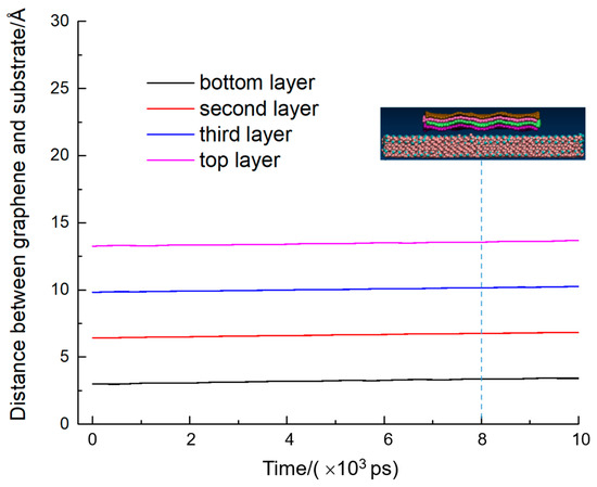
Figure 2.
Exfoliation process in four-layer graphene system, when the vertical upward velocity was 0.4 Å/ps. The dotted blue line shows the trajectory at different points in time.
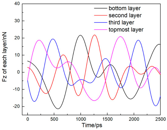
Figure 3.
Fz to exfoliate each layer varying with time in four-layer graphene system, when the vertical upward velocity was 0.4 Å/ps.
Once Vup increases to 0.9 Å/ps, the peeling force induced by velocity is larger than the forces from the SiO2 substrate and underlying layers. The topmost layer of graphene moves away from the SiO2 surface, and is exfoliated finally, as shown in Figure 4. The distance between the topmost layer and the SiO2 surface increases linearly with time. The third layer of graphene goes upward with the topmost layer because the upward force from the topmost layer graphene is greater than the downward force from the SiO2 substrate and the underlying layers. The same phenomenon occurs to the bottom and second layer, which move upward together with the top two layers. Four layers go up at the same rate, and the curves of movement are parallel. From the movement snapshots of the atomic trajectory, relative slipping occurs between the neighbor layers. The SiO2 surface atoms which close to the edge of graphene dislocate, because the interaction between graphene and SiO2 substrate is much larger, Graphene fluctuates a lot, but the trajectories of the three layers are similar.
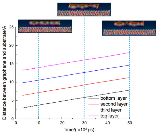
Figure 4.
Exfoliation process in four-layer graphene system at the vertical upward velocity 0.9 Å/ps (the first critical velocity). The dotted blue line shows the trajectory at different points in time.
Figure 5 shows the Z-direction forces of four layers at 0.9 Å/ps. The initial distance between the SiO2 surface and neighbor layer graphene is small. At this time, a repulsive force exists, and the external Fz is negative decreasing with time. With time increasing, the topmost layer is forced by the SiO2 by adhesion forces, and the peeling force becomes larger than 0 nN. At 209 ps, the force exerts on each layer reaches the first maximum value of 44.92 nN, but the Fz of all four layers are still about 0 nN. Although the Fz of each layer fluctuates violently and irregularly, the amplitude reduces.
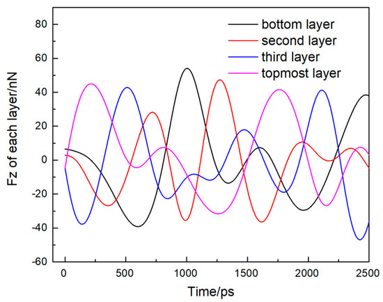
Figure 5.
Fz to exfoliate each layer varying with time in four-layer graphene system, when the vertical upward velocity was 0.9 Å/ps.
Exfoliation processes at different upward velocities between critical Vup 0.9 Å/ps and 10.23 Å/ps were simulated, and 10 Å/ps was shown to illustrate the situation (the trajectory and force of graphene is shown in Figure 6 and Figure 7 respectively). Vup higher than critical velocities 0.9 Å/ps created large enough kinetic energy, the topmost layer is forced to leave the neighbor layers and the distance between the topmost layer and third layer (D34) reaches a maximum of 7.87 Å at 3380 ps, while the topmost layer wound up around the X-axis. Figure 6 shows the variations of morphologies of the topmost layer over time. When the velocity is 10 Å/ps, the front and back ends of the topmost layer are curled symmetrically on the X-axis. As the topmost layer gets further away from the surface of the substrate, the distance between the topmost layer and its neighbor layer becomes larger, the angle of the front and back atomic layer also increases. When D34 gets a maximum value of 7.87 Å, the curled angle is 33.37° (shown in Figure 8a). Because of the interaction between graphene layers, the topmost layer is drawn back to the neighbor layer, and the middle part of the topmost layer gets close to the bottom layer fastest, causing the angle of the curled ends of graphene to increase more. As shown in Figure 8, when D34 is shortened to 5.77 Å, the curled angle reaches a maximum of 48.03°. The end of graphene has no visible curl as D34 recovers to near natural value 3.63 Å. At the same time, the length of the curled ends gradually becomes shorter.
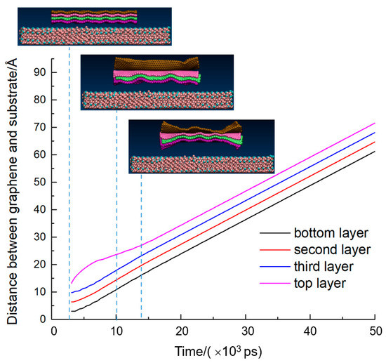
Figure 6.
Exfoliation process in four-layer graphene system, when the vertical upward velocity was 10 Å/ps. The dotted blue line shows the trajectory at different points in time.
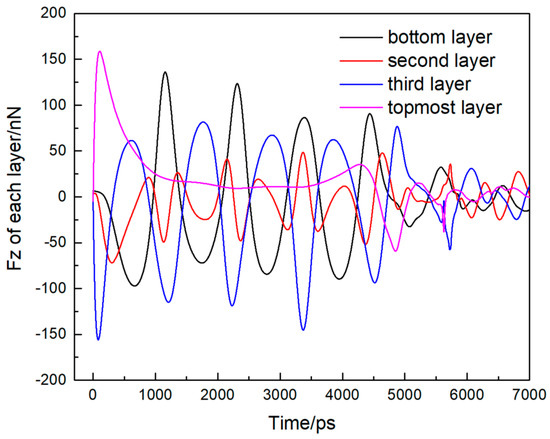
Figure 7.
Fz to exfoliate each layer varying with time in four-layer graphene system, when the vertical upward velocity was 10 Å/ps.
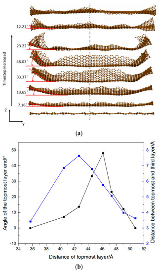
Figure 8.
The topmost layer of the four-layer graphene system curled symmetrically on the X-axis. (a) The snapshots of the topmost layer at different times; (b) The angle of the topmost layer’s end varies with the distance of the topmost layer and the distance between the topmost layer and the third layer.
The bottom three layers keep consistent movements during the exfoliation process, the relative balance D12 (the distance between the bottom and second layer), D23 (the distance between the second and third layer) are both 3.46 Å larger than the natural graphene interlayer gap 3.35 Å. While the topmost layer is pulled back to the neighbor layer after 13,869 ps, the relative balance gap of D34 is also 3.46 Å. From the atomic trajectories, as shown in Figure 6, the four layers keep consistent regular waves at last.
The force of all four graphene layers becomes zero when the distance between the bottom layer and SiO2 substrate is larger than 8.94 Å. Graphene layers interact with each other, and the amplitudes of Z-direction forces of graphene layers decrease when the topmost layer was pulled back to neighbor ones. For example, from Figure 7, the maximum Fz peak of the bottom layer is 136.03 nN, it gradually decreases five times to 31.72 nN at 5556 ps when the D34 is 6.57 Å, and D01 (the distance between the bottom layer and substrate surface) is 14.06 Å. From the Fz peak values of four layers, it can be seen that the maximum Fz of the topmost layer is the largest among the four layers. Although the curves of Fz are complicated, the general rule is: Fz peak of the topmost layer > Fz peak of the bottom layer > Fz peak of the third layer > Fz peak of the second layer. The reason is that the topmost layer and the bottom layer do not just withstand forces from graphene, the topmost layer is applied by the peeling force and Van der Waals’ force from the underlying layers, the bottom layer receives the forces from the SiO2 substrate and neighbor layers.
With Vup 10.23 Å/ps, the topmost layer can be unbound to the SiO2 substrate and moved far away from the underlying graphene and Si surface, as if the spring between the topmost layer and neighbor layer graphene is broken. The movement curve of the topmost layer is nonlinear at the beginning, as shown in Figure 9. Before 7281 ps, when the distance between the topmost layer and SiO2 surface is less than 34.32 Å, the SiO2 substrate and underlying layers still exert forces on the topmost layer graphene. D01 is 14.89 Å, and D34 is 11.45 Å at 7281 ps. The maximum Fz of the topmost layer is 158.68 nN at 106 ps as shown in Figure 10. Without the forces from the neighbor layers, the topmost can get rid of all the constraints, moving up linearly.
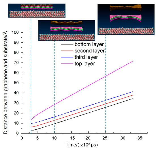
Figure 9.
Exfoliation process in four-layer graphene system, when the vertical upward velocity was 10.23 Å/ps (the second critical velocity). The dotted blue line shows the trajectory at different points in time.
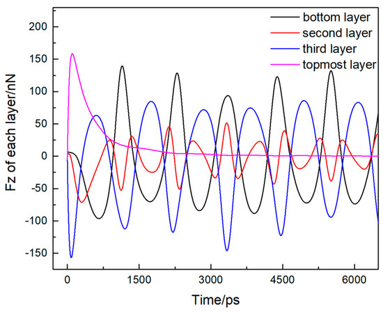
Figure 10.
Fz to exfoliate each layer varying with time in four-layer graphene system, when the vertical upward velocity was 10.23 Å/ps.
The second layer is pulled up by the topmost layer, and because the atoms of graphene edge have unsaturated bonds, the interaction between the SiO2 substrate and the edge of graphene is intense, causing a bulge at the center. The underlying three layers are driven by the topmost layer and moved up linearly with time. Fz of the second layer and third layer varies periodically with time, the maximum Fz of the bottom layer and the third layer is 139.41 nN and 85.33 nN, respectively. The second layer is sandwiched between the bottom layer and third layer, and Fz of the second layer is irregular. The peak values of the Z-direction forces of the underlying three layers decrease gradually, and after 7281 ps, the resultant Fz of all the underlying three layers becomes zero.
When the velocity is faster than 10.23 Å/ps (15 Å/ps as an example), the displacement curve of four-layer graphene and the atomic trajectory is obtained as shown in Figure 11. The phenomena are similar to that when the upward exfoliation velocity is 10.23 Å/ps. The topmost graphene layer gets rid of the constraints from the SiO2 substrate and underlying layers much more quickly. At 68 ps, Fz of the topmost layer is maximum 158.68 nN as shown in Figure 12, then it decreases to zero after 870 ps, and D34 increases from 3.76 Å to 6.04 Å. The underlying three layers are driven by the topmost layer and move up linearly with time at slow speed, and relative slip occurs between the underlying three layers.
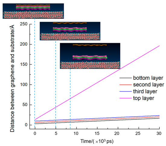
Figure 11.
Exfoliation process in four-layer graphene system, when the vertical upward velocity was 15 Å/ps. The dotted blue line shows the trajectory at different points in time.

Figure 12.
Fz to exfoliate each layer varying with time in the four-layer graphene system, when the vertical upward velocity was 15 Å/ps.
The Fz curves of the second layer and third layer were periodic, the maximum Fz of the bottom layer and the third layer was 138.33 nN at 1014 ps and 86.11 nN at 1612 ps respectively. Fz of the second layer was irregular because it was sandwiched between the bottom layer and the third layer. As a whole, the Fz of the underlying three layers decreased gradually. After 870 ps, the resultant Fz of all the underlying three layers becomes zero, indicating that all these three underlying layers escape from the substrate.
The critical velocities to exfoliate all graphene layers are much lower than that of the topmost layer which are summarized in Figure 13. The critical exfoliate velocity increases with the increasing graphene layers to pull up all the layers. In contrast, the critical exfoliate velocity decreases with the increasing graphene layers to strip the topmost layer. For the one-layer graphene system, the critical Vup is 0.21 Å/ps. While in the two-layer graphene system, the critical Vup to exfoliate the entire two layers and the topmost layer is 0.5 Å/ps and 12.1 Å/ps, respectively. In the three-layer graphene system, the critical Vup to exfoliate the entire three layers increases to 0.81 Å/ps, and the critical exfoliation velocity of the topmost layer is 10.8 Å/ps. In four layers to ten layers graphene systems, the exfoliation critical Vup to exfoliate all graphene layers is in the range of 0.8 Å/ps–3.18 Å/ps, while exfoliation critical Vup to exfoliate the topmost layer is 9.5 Å/ps–10.23 Å/ps.
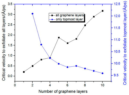
Figure 13.
The critical velocities to exfoliate graphene.
The force to exfoliate graphene is minimum in the one-layer graphene system, the value is 0.0067 nN, and the SiO2 substrate almost does not influence one-layer graphene. In one to four layers graphene systems, with the increasing of graphene layers, it needs larger force to exfoliate all the graphene. However, the maximum force does not increase very much (from 0.0067 nN to 0.046 nN). It suddenly increases to 0.13 nN in the five-layer graphene system, then reaches a maximum of 0.24 nN in the six-layer graphene system. This is because the more layers the peeling force pulled on, the higher Van der Waals force, the greater the force requires. In seven or eight layers graphene systems, pushing inertia forces may be generated, and the maximum pulling force occurs. However, it increases in nine- and ten-layer graphene systems because there are too many graphene layers.
The work carried out by the peeling force is discussed and is shown in Equation (3), and the maximum work is also adhesion energy.
W = F ∗ S
W—the work carried out by the peeling force, F—the peeling force, S—the absolute displacement of graphene.
The maximum work which is also adhesion energy in one to ten layers graphene system is 0.64 mJ/m2 (occurs in the ten-layer graphene system). In one to five layers graphene systems, with graphene layers increasing, the work to exfoliate all the graphene layers increases. It is 0.33 mJ/m2 in the five-layer graphene system and decreases to 0.31 mJ/m2 in the six-layer graphene system, then the maximum work in the seven-layer system increases to 0.38 mJ/m2. On the whole, the principle is messy, but it could be concluded that the necessary work to exfoliate all the graphene layers was very small, in the range of 0.01 mJ/m2–0.64 mJ/m2(shown in Figure 14 and Figure 15).
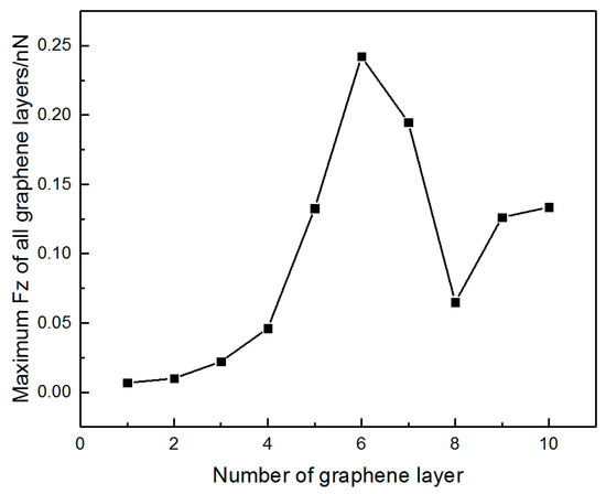
Figure 14.
The maximum Fz to exfoliate all layers.
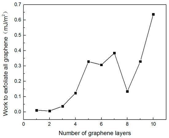
Figure 15.
The maximum work to exfoliate all layers.
The maximum force and maximum work to exfoliate all the graphene are very small. During fabricating graphene-based devices, the frequently used process is the graphene transfer process. This simulation explained that if the binding of graphene and substrate is not unreliable during the transfer process, all graphene layers may fall off.
Exfoliating the topmost layer of graphene requires a much larger force, as shown in Figure 16. Because the bottom layer of graphene is far from the surface of the SiO2 substrate, the influence of the substrate is ignored, so it needs to overcome the Van der Waals forces of the underlying layers to exfoliate the topmost layer. The distance between the topmost layer and the neighbor layer is within the range of Van der Waals forces, the maximum force to exfoliate the topmost layer in the two-layer graphene system is 149.7 nN. The distance between the topmost and the third layer from the top is almost twice more than 3.35 Å, and Van der Waals forces are weakened, so that the maximum force is increased slightly to 158.75 nN. As the number of graphene layers increasing, the distance between the topmost layer and the bottom layer from the top is almost three times larger, which already exceeds the interaction threshold. Therefore, the maximum forces to exfoliate the topmost layer in four to ten layers graphene systems are almost the same as that of the three-layer graphene system. In three to ten layers graphene systems, the average maximum force to exfoliate the topmost layer is 158.63 nN.
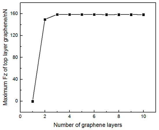
Figure 16.
The maximum force to exfoliate the topmost layer.
The work to exfoliate the topmost layer graphene in two to ten layers systems increases 103 to 104 times than that to exfoliate all layers. In the two-layer graphene system, the work to exfoliate the topmost layer is 136.79 mJ/m2 shown in Figure 17, the average adhesion energy in three to ten layers graphene systems is 149.26 mJ/m2, consistent with the results in the literature [24]. Because of Van der Waals, it is difficult to exfoliate the topmost layers of graphene, reflecting the difficulty of fabricating monolayer graphene.
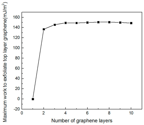
Figure 17.
The maximum work to exfoliate the topmost layer.
In addition, the graphene edges are sometimes passivated by hydrogen, oxygen or nitrogen atoms. In this paper, in order to explore the influence of the edge termination on the exfoliation property, the edge of graphene is passivated by hydrogen in the two-layer graphene system. The critical velocity to exfoliate the topmost layer is higher in the hydrogen-terminated graphene system (13 Å/ps) than that in the unsaturated graphene system (12.1 Å/ps). This is because the hydrogen-terminated graphene system is more stable, it can be seen that the total energy is −56,067 eV, which is lower than that in unsaturated graphene system (−53,541 eV) as shown in Figure 18c.
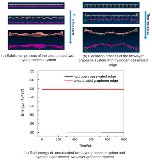
Figure 18.
(a)Exfoliation process of the unsaturated two-layer graphene system, (b) exfoliation process of the hydrogen-passivated two-layer graphene system, and (c) the total energy of them.
4. Conclusions
The exfoliation process of graphene was observed by applying a constant vertical upward velocity to the topmost graphene layer when weakly contacted with SiO2 substrate. In the multilayer graphene system, two critical velocities to exfoliate graphene from the SiO2 surface were found, and three kinds of distinct exfoliation processes took place determined by critical upward velocities. In the four-layer graphene system, the critical upward velocities were 0.9 Å/ps and 10.23 Å/ps. When Vup was smaller than 0.9 Å/ps, it was too slow to generate enough kinetic energy, and four layers can not be exfoliated. By the adhesion from SiO2, graphene layers began to sink to the substrate surface. When Vup was in the range of 0.9 Å/ps and 10.23 Å/ps, all graphene layers can be exfoliated, four layers went up at the same rate, and the movement curves were parallel. With a Vup of more than 10.23 Å/ps, the topmost layer was unbound to the SiO2 substrate. In two to ten layers graphene systems, the critical velocities to exfoliate all graphene layers (0.5 Å/ps–3.18 Å/ps) were much lower than that of the topmost layer (9.5 Å/ps–12.1 Å/ps). The critical exfoliate velocity increased with the increasing graphene layers to pull up all the layers. In contrast, the critical exfoliate velocity decreased with the increasing graphene layers to strip the topmost layer. The adhesion force to exfoliate all the graphene layers was 0.0067 nN–0.24 nN in one to ten layers graphene systems. When exfoliating the topmost layer, under Van der Waals forces between the topmost layer and the neighbor layer, the average maximum force required to exfoliate the topmost layer was 158.75 nN in two to ten layers graphene systems. The maximum work to exfoliate all layers in one to ten layers graphene systems was 0.64 mJ/m2, while the average maximum work to exfoliate the topmost layer in three to ten layers graphene systems was 149.26 mJ/m2, consistent with the results in the literature.
Author Contributions
Conceptualization, Y.Z.; methodology, Q.Z.; investigation, X.P.; writing—original draft preparation, X.P.; writing—review and editing, Q.Z. All authors have read and agreed to the published version of the manuscript.
Funding
The authors would like to thank the National Natural Science Foundation of China (Grant No. 51805425 and U20A20296), Ningbo major special project of the Plan “Science and Technology Innovation 2025” (Grant No. 2020Z023).
Data Availability Statement
Data is contained within the article.
Conflicts of Interest
The authors declare no conflict of interest.
References
- Novoselov, K.S.; Geim, A.K.; Morozov, S.V.; Jiang, D.; Zhang, Y.; Dubonos, S.V.; Grigorieva, I.V.; Firsov, A.A. Electric field effect in atomically thin carbon films. Science 2004, 306, 666–669. [Google Scholar] [CrossRef] [PubMed]
- Lee, C.; Wei, X.; Kysar, J.W.; Hone, J. Measurement of the elastic properties and intrinsic strength of monolayer graphene. Science 2008, 321, 385–388. [Google Scholar] [CrossRef] [PubMed]
- Lee, G.-H.; Cooper, R.C.; An, S.J.; Lee, S.; Van Der Zande, A.; Petrone, N.; Hammerberg, A.G.; Lee, C.; Crawford, B.; Oliver, W.; et al. High-Strength Chemical-Vapor-Deposited Graphene and Grain Boundaries. Science 2013, 340, 1073–1076. [Google Scholar] [CrossRef]
- Morozov, S.V.; Novoselov, K.S.; Katsnelson, M.I.; Schedin, F.; Elias, D.C.; Jaszczak, J.A.; Geim, A.K. Giant Intrinsic Carrier Mobilities in Graphene and Its Bilayer. Phys. Rev. Lett. 2008, 100, 016602. [Google Scholar] [CrossRef]
- Cao, Y.; Fatemi, V.; Demir, A.; Fang, S.; Tomarken, S.L.; Luo, J.Y.; Sanchez-Yamagishi, J.D.; Watanabe, K.; Taniguchi, T.; Kaxiras, E.; et al. Correlated insulator behaviour at half-filling in magic-angle graphene superlattices. Nat. Cell Biol. 2018, 556, 80–84. [Google Scholar] [CrossRef] [PubMed]
- Zhu, S.-E.; Ghatkesar, M.K.; Zhang, C.; Janssen, G.C.A.M. Graphene based piezoresistive pressure sensor. Appl. Phys. Lett. 2013, 102, 161904. [Google Scholar] [CrossRef]
- Chen, C.-C.; Aykol, M.; Chang, C.-C.; Levi, A.F.J.; Cronin, S.B. Graphene-Silicon Schottky Diodes. Nano Lett. 2011, 11, 1863–1867. [Google Scholar] [CrossRef]
- Lin, S.; Lu, Y.; Feng, S.; Hao, Z.; Yan, Y. A High Current Density Direct-Current Generator Based on a Moving van der Waals Schottky Diode. Adv. Mater. 2018, 31, e1804398. [Google Scholar] [CrossRef]
- Yang, J.; Du, W.; Su, Y.; Fu, Y.; Gong, S.; He, S.; Ma, Y. Observing of the super-Planckian near-field thermal radiation between graphene sheets. Nat. Commun. 2018, 9, 1–10. [Google Scholar] [CrossRef]
- Wang, X.; Cheng, Z.; Xu, K.; Tsang, H.K.; Xu, J.-B. High-responsivity graphene/silicon-heterostructure waveguide photodetectors. Nat. Photonics 2013, 7, 888–891. [Google Scholar] [CrossRef]
- Novoselov, K.S.; Fal′ko, V.I.; Colombo, L.; Gellert, P.R.; Schwab, M.G.; Kim, K. A roadmap for graphene. Nat. Cell Biol. 2012, 490, 192–200. [Google Scholar] [CrossRef]
- Geim, A.K.; Novoselov, K.S. The rise of graphene. Nat. Mater. 2007, 6, 183–191. [Google Scholar] [CrossRef]
- Janowska, I.; Ersen, O.; Jacob, T.; Vennégues, P.; Bégin, D.; Ledoux, M.-J.; Pham-Huu, C. Catalytic unzipping of carbon nanotubes to few-layer graphene sheets under microwaves irradiation. Appl. Catal. A Gen. 2009, 371, 22–30. [Google Scholar] [CrossRef]
- Jayasena, B.; Melkote, S.N. An Investigation of PDMS Stamp Assisted Mechanical Exfoliation of Large Area Graphene. Procedia Manuf. 2015, 1, 840–853. [Google Scholar] [CrossRef][Green Version]
- Zong, Z.; Chen, C.-L.; Dokmeci, M.R.; Wan, K.-T. Direct measurement of graphene adhesion on silicon surface by intercalation of nanoparticles. J. Appl. Phys. 2010, 107, 026104. [Google Scholar] [CrossRef]
- Zhang, Y.; Small, J.P.; Pontius, W.V.; Kima, P. Fabrication and electric-field-dependent transport measurements of mesoscopic graphite devices. Appl. Phys. Lett. 2005, 86, 073104. [Google Scholar] [CrossRef]
- Chang, J.S.; Kim, S.; Sung, H.-J.; Yeon, J.; Chang, K.J.; Li, X.; Kim, S. Graphene Nanoribbons with Atomically Sharp Edges Produced by AFM Induced Self-Folding. Small 2018, 14, 1803386. [Google Scholar] [CrossRef]
- Na, S.R.; Suk, J.W.; Ruoff, R.S.; Huang, R.; Liechti, K.M. Ultra Long-Range Interactions between Large Area Graphene and Silicon. ACS Nano 2014, 8, 11234–11242. [Google Scholar] [CrossRef] [PubMed]
- Jayasena, B.; Reddy, C.D.; Subbiah, S. Separation, folding and shearing of graphene layers during wedge-based mechanical exfoliation. Nanotechnology 2013, 24, 205301. [Google Scholar] [CrossRef]
- Li, X.; Zhu, Y.; Cai, W.; Borysiak, M.; Han, B.; Chen, D.; Piner, R.D.; Colombo, L.; Ruoff, R.S. Transfer of Large-Area Graphene Films for High-Performance Transparent Conductive Electrodes. Nano Lett. 2009, 9, 4359–4363. [Google Scholar] [CrossRef]
- Deokar, G.; Avila, J.; Razado-Colambo, I.; Codron, J.-L.; Boyaval, C.; Galopin, E.; Asensio, M.-C.; Vignaud, D. Towards high quality CVD graphene growth and transfer. Carbon 2015, 89, 82–92. [Google Scholar] [CrossRef]
- Liang, X.; Sperling, B.A.; Calizo, I.; Cheng, G.; Hacker, C.A.; Zhang, Q.; Obeng, Y.; Yan, K.; Peng, H.; Li, Q.; et al. Toward Clean and Crackless Transfer of Graphene. ACS Nano 2011, 5, 9144–9153. [Google Scholar] [CrossRef]
- Suk, J.W.; Kitt, A.; Magnuson, C.W.; Hao, Y.; Ahmed, S.; An, J.; Swan, A.K.; Goldberg, B.B.; Ruoff, R.S. Transfer of CVD-grown Monolayer Graphene onto Rrbitrary Substrates. ACS Nano 2011, 5, 6916–6924. [Google Scholar] [CrossRef] [PubMed]
- Boddeti, N.G.; Koenig, S.P.; Long, R.; Xiao, J.L.; Bunch, J.S.; Dunn, M.L. Mechanics of Adhered, Pressurized Graphene Blisters. J. Appl. Mech. 2013, 80, 040909. [Google Scholar] [CrossRef]
- Wang, J.; Sorescu, D.C.; Jeon, S.; Belianinov, A.; Kalinin, S.V.; Baddorf, A.P.; Maksymovych, P. Atomic intercalation to measure adhesion of graphene on graphite. Nat. Commun. 2016, 7, 13263. [Google Scholar] [CrossRef]
- Yu, B.W.; Hou, L.Z.; Wang, S.L.; Huang, H. Environment-Dependent Adhesion Energy of Mica Nanolayers Determined by a Nanomanipulation-Based Bridging Method. Adv. Mater. Interfaces 2019, 6, 1801552. [Google Scholar] [CrossRef]
- Gigli, L.; Kawai, S.; Guerra, R.; Manini, N.; Pawlak, R.; Feng, X.; Müllen, K.; Ruffieux, P.; Fasel, R.; Tosatti, E.; et al. Detachment Dynamics of Graphene Nanoribbons on Gold. ACS Nano 2018, 13, 689–697. [Google Scholar] [CrossRef] [PubMed]
- Xia, W.; Keten, S.; Yang, J.; Zhang, J.; Qiao, J. Molecular Dynamics Simulations of Atomic Diusion during the Al-Cu UltrasonicWelding Process. Materials 2019, 12, 2306. [Google Scholar]
- Klemenz, A.; Pastewka, L.; Balakrishna, S.G.; Caron, A.; Bennewitz, R.; Moseler, M. Atomic Scale Mechanisms of Friction Reduction and Wear Protection by Graphene. Nano Lett. 2014, 14, 7145–7152. [Google Scholar] [CrossRef]
- Sinclair, R.C.; Suter, J.L.; Coveney, P.V. Graphene–Graphene Interactions: Friction, Superlubricity, and Exfoliation. Adv. Mater. 2018, 30, e1705791. [Google Scholar] [CrossRef]
- Lee, S.; Lu, W. Controlling the number of graphene sheets exfoliated from graphite by designed normal loading and frictional motion. J. Appl. Phys. 2014, 116, 024313. [Google Scholar] [CrossRef]
- Stuart, S.J.; Tutein, A.B.; Harrison, J.A. A reactive potential for hydrocarbons with intermolecular interactions. J. Chem. Phys. 2000, 112, 6472–6486. [Google Scholar] [CrossRef]
- Pregler, S.K.; Hayakawa, T.; Yasumatsu, H.; Kondow, T.; Sinnott, S.B. Combined computational and experimental study of Ar beam induced defect formation in graphite. Nucl. Instrum. Methods Phys. Res. Sect. B Beam Interact. Mater. At. 2007, 262, 240–248. [Google Scholar] [CrossRef]
- Brenner, D.W. Empirical potential for hydrocarbons for use in simulating the chemical vapor deposition of diamond films. Phys. Rev. B 1990, 42, 9458–9471. [Google Scholar] [CrossRef] [PubMed]
- Tersoff, J. New empirical approach for the structure and energy of covalent systems. Phys. Rev. B 1988, 37, 6991–7000. [Google Scholar] [CrossRef]
- Fuentes-Cabrera, M.; Rhodes, B.H.; Fowlkes, J.D.; López-Benzanilla, A.; Terrones, H.; Simpson, M.L.; Rack, P.D. Molecular dynamics study of the dewetting of copper on graphite and graphene: Implications for nanoscale self-assembly. Phys. Rev. E 2011, 83, 041603. [Google Scholar] [CrossRef]
- Steve, P. Fast Parallel Algorithms for Short-Range Molecular Dynamics. J. Comput. Phys. 1995, 117, 1–19. [Google Scholar]
- Divya; Kamal, Z. Ratcheting Behaviour of Nano-Scale Copper by Classical Molecular Dynamics Simulations. Bachelor’s Thesis, National Institute of Technology, Rourkela, India, 2013; p. 47. [Google Scholar]
Publisher’s Note: MDPI stays neutral with regard to jurisdictional claims in published maps and institutional affiliations. |
© 2021 by the authors. Licensee MDPI, Basel, Switzerland. This article is an open access article distributed under the terms and conditions of the Creative Commons Attribution (CC BY) license (https://creativecommons.org/licenses/by/4.0/).