Article

Observation of Backflow during the Anihilation of Topologocal Defects in Freely Suspended Smectic Films

1
Department of Nonlinear Phenomena, Institute of Physics, Otto von Guericke University Magdeburg, D-39106 Magdeburg, Germany
2
INSP, Paris Institute of Nanosciences, CNRS, Sorbonne Université, F-75005 Paris, France
*
Authors to whom correspondence should be addressed.
Crystals 2021, 11(4), 430; https://doi.org/10.3390/cryst11040430
Submission received: 28 March 2021 / Revised: 9 April 2021 / Accepted: 12 April 2021 / Published: 16 April 2021
(This article belongs to the Special Issue In Celebration of Noel A. Clark’s 80th Birthday)

Abstract

:
Freely suspended films in the smectic C phase are excellent templates for the study of topological defect dynamics. It is well known that, during the annihilation of a pair of disclinations with strengths +/−1, the +1 defect moves faster because it is carried towards its opponent by backflow, whereas the flow in the vicinity of the −1 defect is negligibly small. This backflow pattern is created by the defect motion itself. An experimental confirmation of this theoretical prediction and its quantitative characterization is achieved here by fluorescence labeling. Film regions near the defect positions are labeled and their displacements are tracked optically.

1. Introduction

Topological defects are a natural feature of condensed matter systems with broken continuous symmetries [1]. They occur in such disparate systems as crystals [2,3,4], superfluid helium [5,6], in colloidal systems [7,8,9,10,11], and liquid crystals [10,11,12,13,14]. Even in biological tissue, they can play an important role in structure formation [15,16]. A comprehensive overview over dislocations and disclinations, their properties, and their applications can be found in Reference [17]. Topological defects created by symmetry-breaking phase transitions have received considerable attention in particle physics, condensed matter physics, and even cosmology [18]. They determine the mechanical properties and the response of solid materials, and they can also serve as building blocks determining the structure of liquid crystal blue phases [19] and twist-grain-boundary phases.
In this study, we focus on a particular feature of such topological defects, the annihilation of point disclinations of opposite topological charges in two dimensions. This scenario has been extensively investigated in analytical studies (e.g., References [20,21,22,23]), numerical simulations (e.g., References [24,25,26,27,28]), and in experiments (e.g., References [29,30,31,32,33,34]).
In a nematic liquid crystal, the coupling between the local orientation and the shear strain can result in advective flow accompanying non-uniform reorientations of the director field. Thus, the motion of (immaterial) defects can induce material transport. Such flow has been recognized early as the physical origin of the asymmetric trajectories of positive and negative topological defects in a pair [32]. The defect with the positive topological charge moves faster towards its negative opponent than the negative defect towards its partner. The moving positive defect creates a backflow pattern that carries the defect by advection towards the annihilation point. The flow field around the negative defect is negligibly small. The negatively charged defect dislocates essentially as a topological structure of the director field in a liquid at rest. In nematic cells, the detection and measurement of this flow field is connected with difficulties. One problem is that the disclinations are line defects that may be pinned at the cell plates, so one actually has to deal with a three-dimensional problem. The second problem is the no-slip condition of the flow field at the cell plates which leads to a complex flow pattern.
One solution to circumvent these difficulties and to explore the dynamics of disclinations in a quasi-twodimensional (2D) geometry are freely suspended smectic films (FSFs). Such films with lateral extensions of up to several centimetres and thicknesses of a few molecular layers mimic quasi-2D fluids. Films of smectic-C (SmC) liquid crystals can be considered as models of (polar) 2D nematics. The analogue of the nematic director in SmC is the projection of the averaged long molecular axes on the smectic layer plane, which is now a vector. In this case, the symmetry is different from 3D nematics and can be described by a 2D vector field. As a result, only integer-strength disclinations are allowed, and half-integer disclinations are forbidden. Noel Clark, together with Chris Muzny, published a study of the dynamics of disclinations in such films [12] already in 1992. They measured the diffusion of a single defect with topological charge s = + 1 in a smectic C FSF. Like a particle, the defect performs Brownian motion in the film plane. In that study, the defect trajectories were analyzed, but it was not discriminated between the diffusion of the defect structure (the virtual particle) relative to the film substance and a displacement of film material with the moving defect.
Multiple defect patterns can be created in SmC FSF when they are slowly expanded to a sphere cap, and, thereafter, this cap is rapidly released back to the flat shape. This triggers a transient transition into the smectic A phase where the c-director vanishes. Upon recovery of the smectic C state, multiple-defect patterns appear that coarsen by defect pair annihilations. This approach is described in the 1994 PhD thesis of Chris Muzny, which was directed by Noel Clark [35]. The elementary process of this coarsening, the defect pair coalescence, has been studied experimentally by Missaoui et al. [34]. An alternative approach to create multiple defect patterns has been described by Stannarius and Harth [36]. There, multiple defects of topological strength s = + 1 were initially trapped in a spot in the film and subsequently released. They repel each other and the initial group disintegrates. Disclinations in smectic C FSF can also interact with inclusions, like islands [37,38], and bind them together. They may serve as links in chains or 2D lattices formed by inclusions, by attractive forces of topological dipoles or quadrupoles [39,40].
Our previous study described the annihilation of defect pairs with the topological strengths of s = ± 1 [34]. It was demonstrated that the mutual orientation of the defect pairs and their orientation with respect to the surrounding director field plays a crucial role in their dynamics. Those experiments support the current theoretical models describing the annihilation in 2D [25,26,28]. However, these models fail to accurately describe the defect velocities and the asymmetry of the trajectories. One reason for those discrepancies is the effect of the above-mentioned backflow. This was demonstrated by Svenšek and Žumer in numerical simulations [24].
Our paper aims to experimentally demonstrate the role of backflow in smectic FSFs. We show that the annihilation of a defect pair with the strengths ± 1 is accompanied by strong material flow in the film plane, which speeds up the velocity of the + 1 defect. The problem of this experiment is that the classical use of tracer particles (or other inclusions) to identify and track flow patterns [41,42,43,44] cannot be employed here. If the liquid crystal is doped with such tracers, they tend to interact with the c-director field. Inclusions will be driven out of the regions of homogeneous or weakly distorted c-director orientation and they will finally occupy the defect cores. This does not necessarily influence the c-director texture near the defect, but the defect is then coupled directly to the film material. This changes the dynamics considerably because the defect can no longer move in the film plane without transporting film material in the surroundings. Thus, we were forced to find other markers in the film. A useful technique is the observation of photo-bleached regions in a film doped with a small amount of fluorescent dye [45]. There is a certain time limit set by the recovery time, but within that time window one can follow the motion of the bleached spot. The local velocity can be determined quantitatively from the displacement of the spot. In repeated experiments, one can choose different positions of the bleached spot relative to the annihilating defect pair and sample the velocity field.
We dedicate this paper to Noel Clark on the occasion of his 80th birthday. Noel Clark has contributed enormously to the exploration of structures and dynamics of these films, and it should be highlighted that it was him who sent the first liquid crystals to space for experiments in microgravity on the International Space Station ISS [46].

2. Materials and Methods

A room-temperature smectic C (SmC) mixture of equal volumes of 5-n-octyl-2-[4-(n-hexyloxy)phenyl] pyrimidine and 5-n-decyl-2-[4-(n-octyloxy) phenyl] pyrimidine was used as the liquid crystal material. The mixture was doped with 5wt% Nile Red dye dissolved in toluene. After the solvent evaporation, freely suspended films (FSF) were drawn manually over a custom-made frame (Figure 1a). Defect pairs were created by piercing of the homogeneously oriented freely suspended film using a glass tip, a method introduced by K. Harth [47]. In order to operate the tip, we used a micromanipulator uMP-3 (Sensapex). Optical observations were made using a Scanning Confocal Laser Microscope SMP8 (Leica) equipped with a photomultiplier detector and a prism monochromator adjusted to the spectral range of 580 nm to 621 nm. Nile Red dye molecules align with the director and cause an anisotropic absorption and emission determined by their orientation (Figure 1a, right). The excitation is performed by linearly polarized laser light. The adsorption efficiency of the linearly polarized light is determined by the angle between the polarization direction P and the transition dipole moment m [48]. The latter is given by the alignment of the director. Since the adsorption efficiency is proportional to cos 2 ( ϕ ) , where ϕ is the angle between P and m , this allows mapping the director field using the intensity of the emitted fluorescence as shown in Figure 2c. The maximum intensity corresponds to the director aligned parallel to the polarization plane. A slight intensity difference between the two maxima of opposite director orientation can be attributed to a marginal tilt of the film. The defect positions are easily identified and located.
In some accompanying experiments, defects of non-doped smectic films were visualized using the classical polarizing microscopy technique with crossed polarizers in reflection. In order to determine the direction of the slow optical axis, and to discriminate between the diagonal orientations, we used a full wave-plate in diagonal orientation to the polarizers (Figure 2a,b).
The local flow was detected using the bleaching function of the microscope. The full laser power of wavelengths 405 nm, 488 nm, 552 nm, and 638 nm was used to bleach a spot-shaped region of interest (ROI) near the defects in order to study the flow behavior. In order to extract the material displacement from the bleached spot, the intensity profile was fitted by the Gaussian fit and the position of the maximum was determined for each frame. Similar techniques have been applied in liquid crystals for the measurement of thermally induced rotations of droplets [49,50].
After bleaching, the ROI in a resting film appears as a black region with circular shape, as shown in Figure 1b top left (defect-free film). The recovery of the bleached spot starts when the illumination is suspended; see Figure 1c. The intensity increases continuously and reaches the equilibrium intensity value within approximately 10 s. At the recording rate of one frame per second, we could acquire at maximum 10 frames before the ROI vanishes. Even if the recovery time of the dye would be much larger, there is a second effect that sets a time limit to the method: The diffusion of the Nile Red molecules in the smectic matrix. If one assumes that it is of the same order of magnitude as the typical self-diffusion of low molecular mass liquid crystals at room temperature, 10 11 10 10 μ m 2 s 1 , the spot will broaden and lose contrast within several seconds. At least, the nearly isotropic diffusion of the dye has no relevant effects on the displacement of the center of the ROI that serves as our marker. The positions of the defects and the bleached ROI were tracked with an accuracy of approximately 1 μ m. In addition to the displacement of the ROI spot, its shape can also change under the influence of flow divergence, providing additional information on the structure of the flow field.

3. Results and Discussion

3.1. Experimental Results

The annihilation dynamics strongly depends on the mutual orientation of the defects [25,26], and on the alignment of the pair respective to the far, undistorted director field [14,26,34]. In the experiment, this orientation cannot be controlled easily. We will use the following notation in the following: a disclination pair is designated as matching when the c-director along the straight line connecting the two defect cores is uniform. In our experiments with strictly tangential + 1 defects, the 1 defect must have an orientation where the c-director is perpendicular to the interconnection line on that line. If its configuration differs from that orientation, one can define a mismatch angle which quantifies the total rotation of the c-director along the defect interconnection. It has been shown that, in an adiabatic model where the defects approach each other via quasi-stationary states, there is a fixed relation between defect pair mismatch and the alignment of the defect pair relative to the undistorted c-director field.
In a first set of experiments, we tried to avoid the complication caused by curved trajectories. Thus we utilize the fact that the defect pairs gradually align during their mutual approach. Precisely at this stage, most of the experiments were performed. Figure 2, left, shows an example of a defect pair with an initially noticeable mismatch (roughly 45 ). The bright feature connecting the defects exhibits a mirrored S-Shape. The image to the right shows the same defects in a nearly aligned state 3 s before their mutual annihilation.
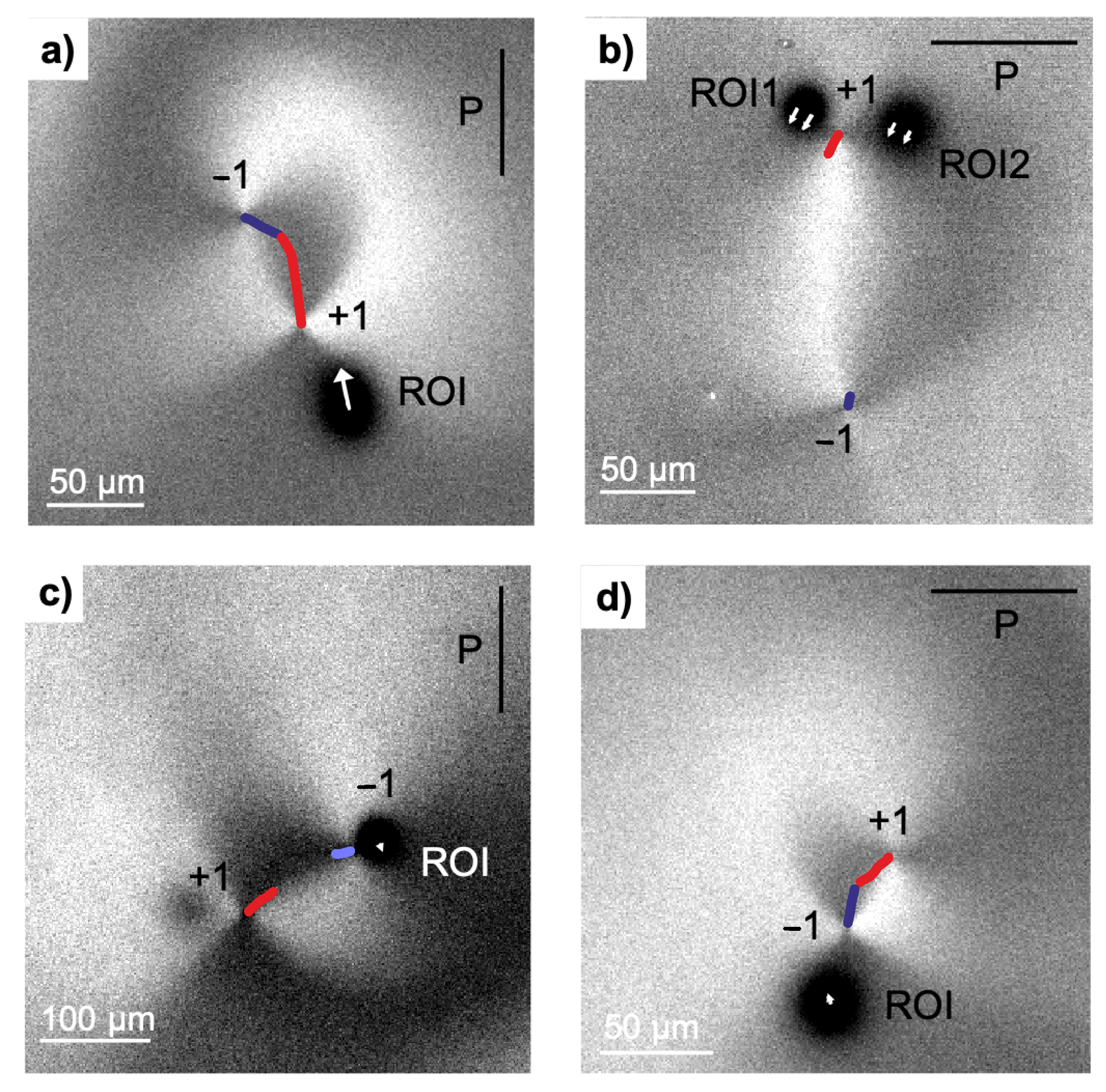
Figure 3 shows snapshots of four defect pairs together with their bleached spots. The textures of the pairs and the ROI are seen at the beginning of the recording, immediately after bleaching stopped. The defect trajectories are represented by blue (for the 1 defect) and red (for the + 1 defect) curves. The time interval during which these trajectories were recorded are approximately 8 s. We have performed experiments with single and double bleached spots (Figure 3a,b, respectively). The flow velocities can be estimated from the analysis of the ROI spots and are given by the arrows.
The first obvious result is that the two defects move towards the annihilation point with different velocities. As predicted by theory [24], the positive defect is faster so that the annihilation does not occur halfway. Besides, the defect pairs have slightly curved trajectories, since the initial defect mismatch is not strictly zero. When flow coupling is disregarded, the models describing the defect speed [22,51] predict a velocity v for each of the defects in the film at rest
v ( + , ) ( r 12 ) = ± K γ 1 ln ( 3.6 / E r ) r 12 .
Here, K is the Frank elastic constant for the c-director in one-constant approximation, E r = γ 1 v r c / K is the Eriksen number, γ 1 is the rotational viscosity of the c-director, r c is the core radius, and r 12 is the distance of the defect cores. As there is no noticeable flow near the 1 defect, this equation can be used as a good reference for the dynamics of the 1 defect, and it is a reasonable approximation for the motion of the + 1 counterpart relative to the moving film.
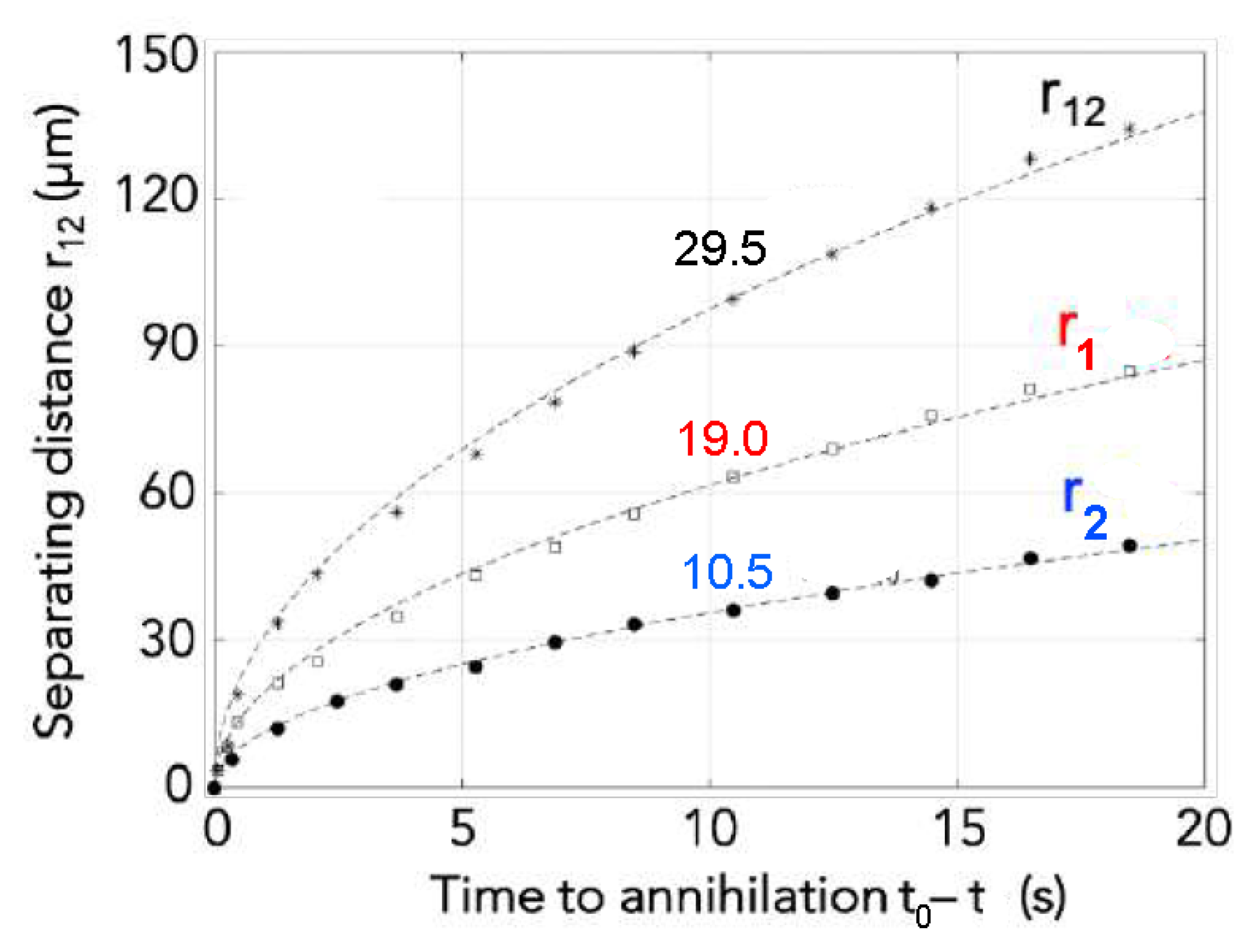
Actual defect velocities can be found in the experiment from the defect positions. For that purpose, we analyzed longer trajectories without the bleaching technique. The distances of the defects from the annihilation center and their mutual distances are shown in Figure 4 for a matching pair. The mutual approach occurs along a straight trajectory. In good approximation, the positions of defect i can be fitted to square-root laws r i = d i t (dashed lines), and their distance is given by r 12 = d 12 t . This corresponds to a velocity v 12 = d 12 2 / ( 2 r 12 ) . It is obvious from these equations that the observed velocities v + and v of the individual disclinations must relate to each other like the coefficients d 1 and d 2 . The + 1 defect is found to move nearly twice as fast as the 1 defect. If we assume that the reason for that difference is backflow coupling and advection, with no significant flow near the 1 defect, then it is natural to equate | v | to | v | in Equation (1). The difference of v + and v is then a signature of flow near the + 1 defect.
Figure 3c,d indeed show that flow is practically absent around the s = 1 disclination point. The bleached spots near the s = 1 defect remain nearly stationary (see Table 1). This is in accordance with the model in Reference [24]. Figure 3a,b show that, in contrast, there is an obvious correlation between the motion of the s = + 1 defect and that of the bleached spot. The spots follow the motion of the adjacent + 1 defect. In the bleaching experiments, the observation time is too short to obtain the square-root law with sufficient accuracy, one rather obtains a snapshot of the dynamics in a certain phase of the defect approach. Technically, it was difficult to manually place the bleaching spot next to one of the defects just before annihilation. Thus, bleaching experiments could be performed only when the defects were still at comparably large distances from each other (e.g., Figure 3b). However, a slight drift of the complete film area in the field of view cannot be avoided. It can reach values of the order of 1 μ m/s. When this drift is perpendicular to the defect interconnection axis, both defect trajectories are tilted to the same side of that axis. This is evident in Figure 3d. If the drift has a component in the direction of the defect interconnection axis, it may tamper the velocity ratio. This is the main error source when the defects are far apart from each other and their approach velocity is small. Drift can be neglected when the defects are fast, close to the annihilation point. If we consider an experimental uncertainty of the order of 1 μ m/s, Table 1 below shows that the velocities v ROI of the regions next to the + 1 defect are comparable to the differences | v + | | v | .
In addition to the displacement of the ROI, the shape of the bleached spot may serve as an additional source of information. When the film material flows during the bleaching phase of about 8 s, the ROI is not a circular spot but it becomes distorted elliptically, with the long axis in the direction of the flow. One can see this effect in Figure 3a. The bleached spot near to the + 1 defect appears elongated in the direction of the induced backflow field. When the defects are far separated as in Figure 3b, the defect motion and corresponding backflow field are small and the bleached region remains circular. The same applies for bleached spots in the vicinity of the 1 defect which is at rest (Figure 3c). Again, drift of the film during bleaching as seen in Figure 3d can also lead to a slight ellipticity of the bleached spot.
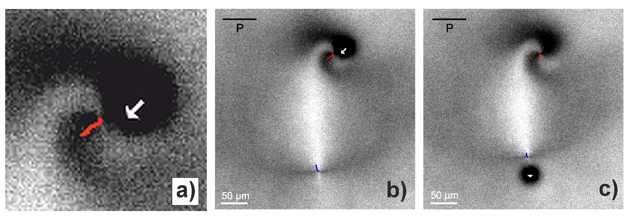
When the orientations of the two defects do not match, i.e., when the director field along the straight line connecting the cores is not uniform, the trajectories are curved [25,26,34]. In some cases, very large mismatch angles have been observed (Figure 5). Since the + 1 defect is pinned to a tangential orientation by the elastic anisotropy (see above), the director field strongly deforms to a spiral shape near the defect [53]. Then, the instant velocity and the trajectory will point sideward, but not towards the 1 opponent. Figure 5 shows that, in such cases, the flow field next to the 1 defect is still negligibly small, while the flow field near the + 1 defect points in the same direction as the defect motion. This is intuitively clear: The velocity field is evoked by the displacement of the + 1 defect alone, irrespective of the location of the far 1 opponent. The quantitative measurements of the displacement velocities in the images of Figure 3 and Figure 5 are given in Table 1.
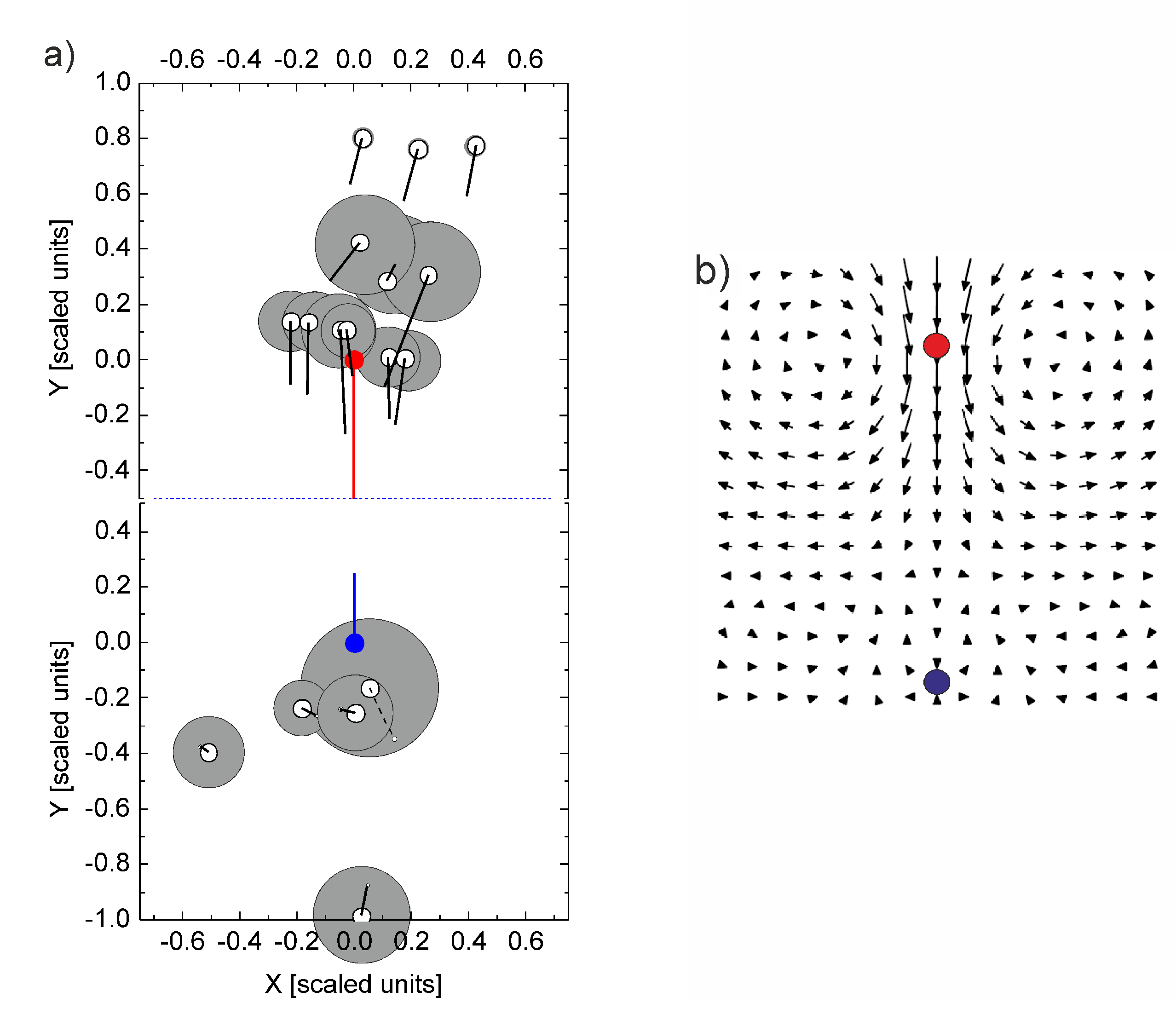
When different experiments are performed with different positions of the ROI, one can try to map the flow field. In principle, one can try to perform several subsequent bleaching experiments with the same pair, but this is extremely challenging. By scaling the velocities measured in different individual experiments of matching pairs, one can compose a map. This is shown in Figure 6a. The approach to construct this map and the symbols used is explained in the following.
First, we assume that the backflow is mainly generated by the displacement of the local disclination and that the influence of the opposite partner in the pair is irrelevant. Thus, we rotate the coordinate system in the region near the + 1 defect (upper half of image Figure 6a) such that the motion of the central + 1 defect is downward. In an aligned pair, this would correspond to the situation shown in the numerical solution of Figure 6b. Now, we have to consider that, in different experiments, the distances of the defect pairs differ; thus, the actual velocities cannot be compared. However, it is reasonable to assume that the ratio of the defect velocity and the backflow is independent of the defect distance in a pair. Thus, we scale all ROI velocities with the absolute velocity determined for the + 1 defect. The initial positions of + 1 defect (red circle) and the ROIs (open black circles) are indicated, and the scaled velocities are shown as black lines. For comparison, the scaled velocity of the disclination is given as a red line. In order to estimate the accuracy and reliability of the velocity data, we estimate the error by assuming a 1 μ m/s drift in the film, in arbitrary directions. Of course, this drift has little effect when the disclinations are close to each other and the velocity for scaling is much larger than a potential drift (upper three ROIs in Figure 6a). It has much larger effects when the defects are far from each other, the approach is slow and the approach velocity becomes comparable to the drift. We mark the estimated error due to drift by grey circles around the original ROI positions. As is seen, most of the black lines indicating the backflow reach much further than the grey uncertainty disks; thus, the analysis clearly evidences a backflow near the + 1 defect that contributes roughly one half of the displacement.
A similar procedure was performed near the 1 defect. Here, the area was scaled again in units of the defect distance, the coordinates were rotated such that the 1 defect moves upward (like in the simulated matching pair in Figure 6b). Velocities were scaled again, with the displacement of the + 1 defect. Errors were estimated in the same way as above. The blue circle is the position of the 1 defect, the blue line its trajectory. Now, it can be seen that all black lines corresponding to the displacements of the ROIs are within the uncertainty limits of the experiment, so the observations are in agreement with the assumption of absent backflow.
When comparing the two parts of Figure 6, note that the upper and lower halves must be kept separate, since they do not belong to the same coordinate systems. All experiments were rotated as explained above, and there are no experiments that produced data in both the upper and lower parts of the image. In each experiment, bleached spots were in the vicinity of either the + 1 defect or the 1 defect.

3.2. Discussion and Theoretical Background

Comparison of the experimental data with the numerically predicted flow field [24] (Figure 6b) shows good qualitative agreement. Note, however, that the backflow is not necessarily towards the opposing defect if there is a mismatch in the pair. The direction of the backflow is determined by the direction of motion of the + 1 defect.
To elucidate the effect of the flow on the annihilation dynamics, we have to consider the dynamic equations for the director and the mass transport in the film. In thin SmC films, the tilted molecular order can be described by the c-director, which is the order parameter of the system. The free energy density is given by the expansion in powers of c , the projection of the director onto the smectic layer normal, and its gradients.
f = A 2 c 2 + C 2 c 4 + K s 2 ( · c ) 2 + K b 2 ( × c ) 2 ,
where A and C are the Landau coefficient of the free energy expansion, K s is the splay coefficient for the n director, and K b is a mixture of the bend and twist constants. The equilibrium magnitude of the order parameter c , which is related to the equilibrium tilt angle, is given by c 0 = A / C . A correlation length is determined by the ratio of the mean elastic coefficient K = ( K b + K s ) / 2 and the Landau coefficient A by ξ = K / | 2 A | . It is typically of the order of a few nanometers and characterizes the radius of the defect core. In the center of the core, the tilt angle decreases to zero.
The dynamic equations for the director and the flow are given in References [24,54]. In particular, two stress contributions determine the defect dynamics: the elastic stress σ i j e and viscous stress σ i j v given by
σ i j e = f i c k j c k ,
and
σ i j v = 1 2 γ 1 N i c j c i N j + 1 2 γ 2 N i c j + c i N j + α 1 c k c l A k l c i c j + α 4 A i j + α 5 c i A j k c k + α 6 A i k c k c j ,
where α i are the Leslie coefficients, γ 1 = α 3 α 2 is the rotational viscosity, γ 2 = α 3 + α 2 , A i j = 1 2 i v j + j v i , and N i = c ˙ i + W i j c j with the antissymetric tensor W i j = 1 2 i v j j v i . The effects of those terms on the flow are different for defects with topological charges + 1 and 1 . As shown by Svenšek and Žumer [24], the flow asymmetry can be descriptively explained considering the symmetries of the viscous and elastic stresses upon an exchange of the two defects. This can be demonstrated by a reflection of the director configuration along the line connecting the defects. As a result of the reflection, the + 1 defect transforms into the 1 and vice versa. Under this reflection, the component of the viscous stress with γ 1 is asymmetric, and the elastic stress remains symmetric. This determines the asymmetry of the defect velocities driven by the advective flow. In the hydrodynamic description, the flow driven during the mutual approach of the pair by the symmetric elastic stress has the same effect on both disclinations, speeding up the annihilation. In contrast, the antisymmetry of the γ 1 term results in the displacement of both defects in the same direction, thus accelerating the positive defect and retarding the negative one.
Quantitatively, it is possible to conclude from the asymmetry of the annihilation process on viscosity ratios: In the absence of flow, the speeds of both defects relative to the film material should be nearly the same for both defects, regardless of the misalignment. The mutually attracting forces are the same and the counteracting viscous forces of a moving defect depend only on the velocities relative to the film, but not on the sign of the topological charge s [21], in good approximation. However, the + 1 defect in the annihilating pair actually moves nearly twice as fast in the laboratory frame as the 1 defect, as shown experimentally. The relative contributions of the γ 1 and α 4 terms in the viscous stress tensor determine the ratio of velocities of the two defects. For half-integer defects, this has been confirmed in numerical simulations by Tang and Selinger [27]. We conclude that the observed speed ratio close to two is primarily caused by the ratio of the viscosity coefficients, which are not known for the investigated material. In Reference [24], a velocity ratio of roughly 2 is reached when γ 1 is approximately twice as large as α 4 . Interestingly, Reference [27] predicts a similar velocity anisotropy of a ± 1 / 2 defect pair for the same ratio of γ 1 / α 4 .
Other factors may contribute to the velocity asymmetry of annihilating defects, as well. The elastic anisotropy K s K b , for instance, may also contribute to the asymmetry of the motion [24,55,56]. In our system, K s 2 K b , which makes the one-constant approximation difficult to apply. This influence is, however, expected to be much smaller than that of the backflow effect (see references in Reference [14]).

4. Conclusions

We have demonstrated qualitatively and quantitatively that a topological defect of strength + 1 in a smectic C liquid crystalline FSF is able to create substantial material flow when it moves in the film plane. This conclusion can be generalized, it is not exclusively the consequence of a defect pair annihilation but is a feature directly connected with the director field reorientation around the moving disclinations. We have assumed here, similar to earlier theoretical treatments of this annihilation process, that the smectic C hydrodynamics in the 2D film geometry can be treated within the nematodynamic model of Leslie and Ericksen, by substituting the respective elastic and viscosity parameters by their appropriate equivalents for the c-director. Thus, the result can also be seen as a confirmation of this backflow effect in nematic cells.
Here, the focus was laid on single isolated defect pairs as the elementary process of defect pattern coarsening. There are other situations where backflow coupling of a moving defect can have essential consequences. Muzny and Clark [12] have studied the diffusion of a single + 1 defect in a FSF and analyzed its Brownian motion within a model that disregards flow coupling. On the basis of the present experimental results, it is clear that backflow must be taken into consideration for an isolated + 1 defect, as well. It should indeed speed up its diffusion by a factor of two. On the other hand, 1 defects in a similar film would have a slower diffusion constant, because the flow generated by this type of disclinations is considerably smaller. Another problem where the backflow should be incorporated in models is the coarsening of multi-defect patterns [35]. However, while the flow coupling may speed up the overall coarsening process, the scaling exponent for the defect number versus time will not be affected.
The fluorescence bleaching method developed here is limited to short time scales of a few seconds, which prevents to determine accurate defect velocity data when the defects are separated more than 100 μ m, but on short distances it can yield reliable quantitative data. An improved method can be developed where multiple lines in a grid are bleached instead of single spots. This would allow to get information on the complete flow field from single experiments.

Author Contributions

Conceptualization, R.S.; methodology, A.E. and R.S.; formal analysis, R.S. and A.M.; investigation, A.M. and A.E.; writing—original draft preparation, A.M., A.E., and R.S.; writing—review and editing, A.E., E.L., and R.S.; supervision, R.S. and E.L.; funding acquisition, R.S., E.L., and A.E. All authors have read and agreed to the published version of the manuscript.

Funding

This research was funded by the German Science Foundation, grant numbers STA 425/44-1, INST 272/260-1 and ER 467/14-1, and by a PHD grant of the Centre National d’Etude Spatiale (CNES).

Institutional Review Board Statement

Not applicable.

Informed Consent Statement

Not applicable.

Data Availability Statement

Data are available in the lab of A.E. and R.S.

Acknowledgments

The authors acknowledge Kirsten Harth (Otto von Guericke University) and Daniel Svenšek (University of Ljubljana) for fruitful discussions and comments. Péter Salamon (Wigner Reserch Centre for Physics, Budapest) is acknowledged for contributing some of the experimental images.

Conflicts of Interest

The authors declare no conflict of interest.

Sample Availability

Samples of the mesogenic compounds can be acquired commercially from Synthon Chemicals.

Abbreviations

The following abbreviations are used in this manuscript:
FSFfreely suspended smectic film
ROIregion of interest
SmCsmectic C

References

  1. Mermin, N.D. The topological theory of defects in ordered media. Rev. Mod. Phys. 1979, 51, 591–648. [Google Scholar] [CrossRef]
  2. Roessler, U.K.; Bogdanov, A.N.; Pfleiderer, C. Spontaneous skyrmion ground states in magnetic metals. Nature 2006, 442, 797–801. [Google Scholar] [CrossRef] [PubMed] [Green Version]
  3. Woods, C.R.; Britnell, L.; Eckmann, A.; Ma, R.S.; Lu, J.C.; Guo, H.M.; Lin, X.; Yu, G.L.; Cao, Y.; Gorbachev, R.V.; et al. Commensurate-incommensurate transition in graphene on hexagonal boron nitride. Nat. Phys. 2014, 10, 451–456. [Google Scholar] [CrossRef]
  4. Vasudevan, R.K.; Neumayer, S.M.; Susner, M.A.; McGuire, M.A.; Pantelides, S.T.; Maksymovych, P.; Leonard, D.N.; Balke, N.; Borisevich, A.Y. Domains and Topological Defects in Layered Ferrielectric Materials: Implications for Nanoelectronics. ACS Appl. Nano Mater. 2020, 3, 8161–8166. [Google Scholar] [CrossRef]
  5. Bauerle, C.; Bunkov, Y.M.; Fisher, S.N.; Godfrin, H.; Pickett, G.R. Laboratory simulation of cosmic string formation in the early Universe using superfluid 3He. Nature 1996, 382, 332–334. [Google Scholar] [CrossRef]
  6. Ruutu, V.M.H.; Eltsov, V.B.; Gill, A.J.; Kibble, T.W.B.; Krusius, M.; Makhlin, Y.G.; Placais, B.; Volovik, G.E.; Xu, W. Vortex formation in neutron-irradiated superfluid 3He as an analogue of cosmological defect formation. Nature 1996, 382, 334–336. [Google Scholar] [CrossRef] [Green Version]
  7. Bowick, M.J.; Giomi, L. Two-dimensional matter: Order, curvature and defects. Adv. Phys. 2009, 58, 449–563. [Google Scholar] [CrossRef]
  8. Irvine, W.T.M.; Vitelli, V.; Chaikin, P.M. Pleats in crystals on curved surfaces. Nature 2010, 468, 947–951. [Google Scholar] [CrossRef]
  9. Irvine, W.T.M.; Hollingsworth, A.D.; Grier, D.G.; Chaikin, P.M. Dislocation reactions, grain boundaries, and irreversibility in two-dimensional lattices using topological tweezers. Proc. Natl. Acad. Sci. USA 2013, 110, 15544–15548. [Google Scholar] [CrossRef] [Green Version]
  10. Musevic, I.; Skarabot, M.; Tkalec, U.; Ravnik, M.; Zumer, S. Two-dimensional nematic colloidal crystals self-assembled by topological defects. Science 2006, 313, 954–958. [Google Scholar] [CrossRef]
  11. Tkalec, U.; Ravnik, M.; Copar, S.; Zumer, S.; Musevic, I. Reconfigurable Knots and Links in Chiral Nematic Colloids. Science 2011, 333, 62–65. [Google Scholar] [CrossRef] [Green Version]
  12. Muzny, C.; Clark, N. Direct observation of the Brownian-motion of a liquid-crystal topological defect. Phys. Rev. Lett. 1992, 68, 804–807. [Google Scholar] [CrossRef]
  13. Alexander, G.P.; Chen, B.G.G.; Matsumoto, E.A.; Kamien, R.D. Colloquium: Disclination loops, point defects, and all that in nematic liquid crystals. Rev. Mod. Phys. 2012, 84, 497–514. [Google Scholar] [CrossRef] [Green Version]
  14. Harth, K.; Stannarius, R. Topological Point Defects of Liquid Crystals in Quasi-Two-Dimensional Geometries. Front. Phys. 2020, 8, 112. [Google Scholar] [CrossRef]
  15. Beliaev, M.; Zoellner, D.; Pacureanu, A.; Zaslansky, P.; Zlotnikov, I. Dynamics of topological defects and structural synchronization in a forming periodic tissue. Nat. Phys. 2021. [Google Scholar] [CrossRef]
  16. Fardin, M.A.; Ladoux, B. Living proof of effective defects. Nature 2021, 17, 172. [Google Scholar]
  17. Kleman, M.; Friedel, J. Disclinations, dislocations, and continuous defects: A reappraisal. Rev. Mod. Phys. 2008, 80, 61–115. [Google Scholar] [CrossRef] [Green Version]
  18. Chuang, I.; Durrer, R.; Turok, N.; Yurke, B. Cosmology in the Laboratory: Defect Dynamics in Liquid Crystals. Science 1991, 251, 1336–1342. [Google Scholar] [CrossRef]
  19. Wright, D.C.; Mermin, N.D. Crystalline liquids—The blue phases. Rev. Mod. Phys. 1989, 61, 385–432. [Google Scholar] [CrossRef]
  20. Dafermos, C.M. Disinclinations in Liquid Crystals. Q. J. Mech. Appl. Math. 1970, 23, S49. [Google Scholar] [CrossRef]
  21. Imura, H.; Okano, K. Friction coefficient for a moving disclination in a nematic liquid crystal. Phys. Lett. 1973, A42, 403. [Google Scholar] [CrossRef]
  22. Pleiner, H. Dynamics of a disclination point in smectic-C and -C* liquid-crystal films. Phys. Rev. A 1988, 37, 3986. [Google Scholar] [CrossRef] [PubMed]
  23. Kleman, M.; Lavrentovich, O.D. Soft Matter Physics: An Introduction; Springer: Berlin, Germany, 2003. [Google Scholar]
  24. Svenšek, D.; Žumer, S. Hydrodynamics of Pair-Annihilating Disclinations in SmC Films. Phys. Rev. Lett. 2003, 90, 155501, Erratum in 2003, 90, 219901. [Google Scholar] [CrossRef] [Green Version]
  25. Vromans, A.J.; Giomi, L. Orientational properties of nematic disclinations. Soft Matter 2016, 12, 6490–6495. [Google Scholar] [CrossRef] [PubMed] [Green Version]
  26. Tang, X.; Selinger, J.V. Orientation of topological defects in 2D nematic liquid crystals. Soft Matter 2017, 13, 5481. [Google Scholar] [CrossRef] [PubMed] [Green Version]
  27. Tang, X.; Selinger, J.V. Theory of defect motion in 2D passive and active nematic liquid crystals. Soft Matter 2019, 15, 587. [Google Scholar] [CrossRef] [PubMed] [Green Version]
  28. Tang, X.; Selinger, J.V. Annihilation trajectory of defects in smectic-C films. Phys. Rev. E 2020, 102, 012702. [Google Scholar] [CrossRef]
  29. Pargellis, A.N.; Finn, P.; Goodby, J.W.; Panizza, P.; Yurke, B.; Cladis, P.E. Defect dynamics and coarsening dynamics in smectic-C films. Phys. Rev. A 1992, 46, 7765. [Google Scholar] [CrossRef] [PubMed]
  30. Blanc, C.; Svenšek, D.; Žumer, S.; Nobili, M. Dynamics of Nematic Liquid Crystal Disclinations: The Role of the Backflow. Phys. Rev. Lett. 2005, 95, 097802. [Google Scholar] [CrossRef] [Green Version]
  31. Dierking, I.; Marshall, O.; Wright, J.; Bulleid, N. Annihilation dynamics of umbilical defects in nematic liquid crystals under applied electric fields. Phys. Rev. E 2005, 71, 061709. [Google Scholar] [CrossRef]
  32. Oswald, P.; Ignes-Mullol, J. Backflow-Induced Asymmetric Collapse of Disclination Lines in Liquid Crystals. Phys. Rev. Lett. 2006, 95, 027801. [Google Scholar] [CrossRef] [PubMed] [Green Version]
  33. Dierking, I.; Ravnik, M.; Lark, E.; Healey, J.; Alexander, G.P.; Yeomans, J.M. Anisotropy in the annihilation dynamics of umbilic defects in nematic liquid crystals. Phys. Rev. E 2012, 85, 021703. [Google Scholar] [CrossRef]
  34. Missaoui, A.; Harth, K.; Salamon, P.; Stannarius, R. Annihilation of point defect pairs in freely suspended liquid crystal films. Phys. Rev. Res. 2020, 2, 013080. [Google Scholar] [CrossRef] [Green Version]
  35. Muzny, C. Properties of Defects in Freely Suspended Smectic C Thin Films. Ph.D. Thesis, University of Colorado, Boulder, CO, USA, 1994. [Google Scholar]
  36. Stannarius, R.; Harth, K. Defect Interactions in Anisotropic Two-Dimensional Fluids. Phys. Rev. Lett 2016, 117, 157801. [Google Scholar] [CrossRef] [PubMed]
  37. Pettey, D.; Lubensky, T.C.; Link, D.R. Topological Inclusions in 2D Smectic-C Films. Liq. Cryst. 1998, 25, 579. [Google Scholar] [CrossRef]
  38. Silvestre, N.M.; Patricio, P.; Telo da Gama, M.M.; Pattanaporkratana, A.; Park, C.S.; Maclennan, J.E.; Clark, N.A. Modeling dipolar and quadrupolar defect structures generated by chiral islands in freely suspended liquid crystal films. Phys. Rev. E 2009, 80, 041708. [Google Scholar] [CrossRef] [Green Version]
  39. Bohley, C.; Stannarius, R. Inclusions in free standing smectic liquid crystal films. Soft Matter 2008, 4, 683. [Google Scholar] [CrossRef]
  40. Dolganov, P.V.; Cluzeau, P.; Dolganov, V.K. Interaction and self-organization of inclusions in two-dimensional free-standing smectic films. Liq. Cryst. Rev. 2019, 7, 1. [Google Scholar] [CrossRef]
  41. Cheung, C.; Hwang, Y.; Wu, X.; Choi, H. Diffusion of particles in free-standing liquid films. Phys. Rev. Lett. 1996, 76, 2531–2534. [Google Scholar] [CrossRef] [PubMed]
  42. Nguyen, Z.H.; Atkinson, M.; Park, C.S.; Maclennan, J.; Glaser, M.; Clark, N. Crossover between 2D and 3D Fluid Dynamics in the Diffusion of Islands in Ultrathin Freely Suspended Smectic Films. Phys. Rew. Lett. 2010, 105, 268304. [Google Scholar] [CrossRef]
  43. Eremin, A.; Baumgarten, S.; Harth, K.; Stannarius, R.; Nguyen, Z.H.; Goldfain, A.; Park, C.S.; Maclennan, J.E.; Glaser, M.A.; Clark, N.A. Two-dimensional microrheology of freely suspended liquid crystal films. Phys. Rev. Lett. 2011, 107, 268301. [Google Scholar] [CrossRef] [Green Version]
  44. Qi, Z.; Nguyen, Z.H.; Park, C.S.; Glaser, M.A.; Maclennan, J.E.; Clark, N.A.; Kuriabova, T.; Powers, T.R. Mutual Diffusion of Inclusions in Freely Suspended Smectic Liquid Crystal Films. Phys. Rev. Lett. 2014, 113, 128304. [Google Scholar] [CrossRef] [Green Version]
  45. Ishikawa-Ankerhold, H.C.; Ankerhold, R.; Drummen, G.P.C. Advanced Fluorescence Microscopy Techniques-FRAP, FLIP, FLAP, FRET and FLIM. Molecules 2012, 17, 4047–4132. [Google Scholar] [PubMed] [Green Version]
  46. Clark, N.A.; Eremin, A.; Glaser, M.A.; Hall, N.R.; Harth, K.; Klopp, C.; Maclennan, J.E.; Park, C.S.; Stannarius, R.; Tin, P.; et al. Realization of hydrodynamic experiments on quasi-2D liquid crystal films in microgravity. Adv. Space Res. 2017, 60, 737. [Google Scholar] [CrossRef] [Green Version]
  47. Harth, K. Otto von Guericke University, Magdeburg. Personal communication, 2009. [Google Scholar]
  48. Smalyukh, I.I. Confocal Microscopy of Director Structures in Strongly Confined and Composite Systems. Mol. Cryst. Liq. Cryst. 2007, 477, 23–41. [Google Scholar] [CrossRef]
  49. Yoshioka, J.; Ito, F.; Suzuki, Y.; Takahashi, H.; Takizawa, H.; Tabe, Y. Director/barycentric rotation in cholesteric droplets under temperature gradient. Soft Matter 2014, 10, 5869. [Google Scholar] [CrossRef] [PubMed]
  50. Poy, G.; Oswald, P. Do Lehmann cholesteric droplets subjected to a temperature gradient rotate as rigid bodies? Soft Matter 2016, 12, 2604. [Google Scholar] [CrossRef]
  51. Ryskin, G.; Kremenetsky, M. Drag Force on a Line Defect Moving through an Otherwise Undisturbed Field: Disclination Line in a Nematic Liquid Crystal. Phys. Rev. Lett. 1991, 67, 1574. [Google Scholar] [CrossRef]
  52. Missaoui, A. Dynamics of Topological Defects in Freely Suspended Smectic Liquid Crystal Films and Bubbles. Ph.D. Thesis, Otto von Guericke University, Magdeburg and Sorbonne University, Paris, France, 2021. [Google Scholar]
  53. Eremin, A.; Bohley, C.; Stannarius, R. Stick-slip dynamics around a topological defect in free standing smectic films. Phys. Rev. E 2006, 74, 040701(R). [Google Scholar] [CrossRef]
  54. Stewart, I.W. The Static and Dynamic Continuum Theory of Liquid Crystals; CRC Press: Boca Raton, FL, USA, 2019. [Google Scholar] [CrossRef]
  55. Tóth, G.; Denniston, C.; Yeomans, J.M. Hydrodynamics of Topological Defects in Nematic Liquid Crystals. Phys. Rev. Lett. 2002, 88, 105504. [Google Scholar] [CrossRef] [Green Version]
  56. Brugués, J.; Ignés-Mullol, J.; Casademunt, J.; Sagués, F. Probing Elastic Anisotropy from Defect Dynamics in Langmuir Monolayers. Phys. Rev. Lett. 2008, 100, 037801. [Google Scholar] [CrossRef] [PubMed] [Green Version]
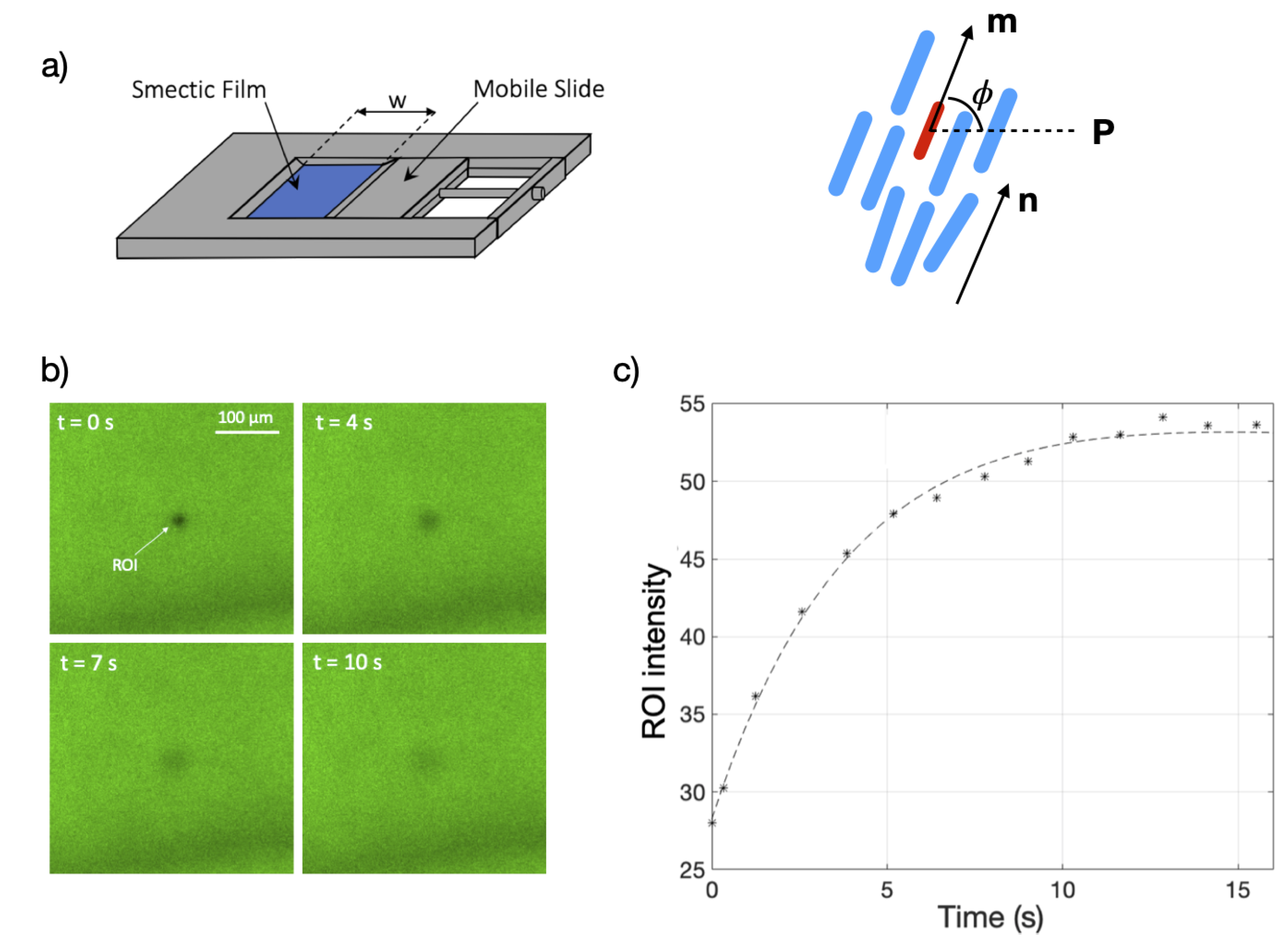
Figure 1. (a) Left: Scheme of the film holder mounted on the microscopy table. Right: Schematic of the dye orientation drawn in red in the nematic matrix drawn in blue. n is the nematic director, m is the transition moment, and P is the polarization plane of the excitation beam. (b) Snapshots from the experiment showing the fluorescence intensity recovery of a bleached region (exposed for 8 s to full laser power before t = 0 ). The film does not contain defects in the vicinity of the region of interest (ROI). (c) Time dependence of the measured mean intensity of the bleached ROI presented in Figure 1b. The recovery time is about 10 s. The dashed line is an exponential fit.
Crystals 11 00430 g001
Figure 2. Snapshots of two defect pairs: The + 1 defect has always tangential orientation of the c-director near the core. The 1 defect is initially rotated respective to the partner (in mismatch) so that the director field along a straight line connecting the cores is not uniform. Image (a) was recorded 16 s before annihilation. During the mutual approach, the mismatch angle gradually reduces to zero. This state is almost reached in image (b), 3 s before annihilation. Yellow bars symbolize 50 μ m. Images were recorded in polarized light with crossed polarizers (black lines) and a diagonal wave plate (slow axis: diagonal yellow line). Bluish regions characterize the c-director in northeast or southwest direction, while orange regions indicate a c-director orientation in southeast or northwest directions. In magenta regions, the c-director is either horizontal or vertical in the images. (c) Defects pair observed in fluorescence mode (top: +1 defect, bottom: −1 defect). The black arrows sketch the c-director. The polarizer orientation is indicated by a black bar. Images (a,b) are courtesy of Péter Salamon and Kirsten Harth.
Crystals 11 00430 g002
Figure 3. Trajectories of the defects and the flow field in the bleached regions: The snapshots show the pairs at the beginning of the recording, immediately after bleaching stopped. The + 1 defect, 1 defect, and ROI trajectories are shown in red, blue and white respectively. The motion of the ROI near the positive defect (a,b) follows the motion of the defect. The ROI near the negative defect (c,d) does not move noticeably. (a) A single ROI bleach; (b) a double ROI bleach. The trajectories of the + 1 defect, of the 1 defect, and of the ROI are shown in red, blue and white, respectively. The disclinations and ROI are tracked for 8 s. The position of the excitation beam polarization is given by black lines.
Crystals 11 00430 g003
Figure 4. Distances of two matching defects with respect to the annihilation point. The graphs show the defect separation r 12 and the distances r 1 of the + 1 defect and r 2 of the 1 defect from the point where they finally meet and annihilate. The dashed lines are square-root fits r = d t , and the numbers give d in units of μ m s 1 / 2 . Image adapted from Reference [52].
Crystals 11 00430 g004
Figure 5. Flow field in a strongly mismatched pair of defects (mismatch angle approximately 180 ). Because of the mismatch of the orientations, the defects do not approach each other along the straight interconnection line. The images show the pair with ROI near the + 1 defect (b) and the 1 defect (c). (a) A magnification of the + 1 defect and ROI from image (b).
Crystals 11 00430 g005
Figure 6. Advective flow around disclinations in a ± 1 pair. (a) Flow field determined experimentally using the fluorescence bleaching method. The velocity bars are normalized with respect to that of the + 1 defect (see text). The motion of the s = + 1 is accompanied by the flow in the same direction of motion. In contrast, the flow is nearly absent in the vicinity of the s = 1 defect. (b) Numerical flow velocity field showing the formation of the flow vortices around the s = + 1 defect. Image (b) reproduced with permission from Svenšek and Žumer [24], copyright American Physical Society.
Crystals 11 00430 g006
Table 1. Measured flow fields in the images shown in this paper. All velocities are given in μ m/s. The indices ROI+ and ROI− refer to spots near the disclinations with the respective sign. For Figure 3b, the average of the velocities of both bleached spots is given. The accuracy of the velocity data is of the order of 1  μ m/s.
Figure v + v v ROI + v ROI
Figure 3a6.02.62.6-
Figure 3b2.61.71.2-
Figure 3c4.02.2-<0.2
Figure 3d4.53.2-0.5
Figure 5a,b1.91.71.2-
Figure 5c1.21.2-<0.3
Publisher’s Note: MDPI stays neutral with regard to jurisdictional claims in published maps and institutional affiliations.