Abstract
Tetramethyl-tetraselenafulvalene (TMTSF) and bis(ethylenedithio)-tetrathiafulvalene (BEDT-TTF) are flagship precursors in the field of molecular (super)conductors. The electrocrystallization of these donors in the presence of (n-Bu4N)TaF6 or mixtures of (n-Bu4N)TaF6 and (n-Bu4N)PF6 provided Bechgaard salts formulated as (TMTSF)2(TaF6)0.84(PF6)0.16, (TMTSF)2(TaF6)0.56(PF6)0.44, (TMTSF)2(TaF6)0.44(PF6)0.56 and (TMTSF)2(TaF6)0.12(PF6)0.88, together with the monoclinic and orthorhombic phases δm-(BEDT-TTF)2(TaF6)0.94(PF6)0.06 and δo-(BEDT-TTF)2(TaF6)0.43(PF6)0.57, respectively. The use of BEDT-TTF and a mixture of (n-Bu4N)TaF6/TaF5 afforded the 1:1 phase (BEDT-TTF)2(TaF6)2·CH2Cl2. The precise Ta/P ratio in the alloys has been determined by an accurate single crystal X-ray data analysis and was corroborated with solution 19F NMR measurements. In the previously unknown crystalline phase (BEDT-TTF)2(TaF6)2·CH2Cl2 the donors organize in dimers interacting laterally yet no organic-inorganic segregation is observed. Single crystal resistivity measurements on the TMTSF based materials show typical behavior of the Bechgaard phases with room temperature conductivity σ ≈ 100 S/cm and localization below 12 K indicative of a spin density wave transition. The orthorhombic phase δo-(BEDT-TTF)2(TaF6)0.43(PF6)0.57 is semiconducting with the room temperature conductivity estimated to be σ ≈ 0.16–0.5 S/cm while the compound (BEDT-TTF)2(TaF6)2·CH2Cl2 is also a semiconductor, yet with a much lower room temperature conductivity value of 0.001 to 0.0025 S/cm, in agreement with the +1 oxidation state and strong dimerization of the donors.
1. Introduction
In the realm of tetrathiafulvalene (TTF) precursors and materials derived thereof [,,,,], tetramethyl-tetraselenafulvalene (TMTSF) and bis(ethylenedithio)-tetrathiafulvalene (BEDT-TTF) (Scheme 1) occupy a prominent place because they are both related to important discoveries in the field of molecular (super)conductors [] and interest in condensed matter physics has never wavered [,]. Particularly relevant in the case of TMTSF are the first superconducting organic mixed valence radical cation salts (TMTSF)2A (A– = PF6–, AsF6–, SbF6–, TaF6–, ClO4–, etc.), also known as the Bechgaard salts [,,,,]. For example, in the series (TMTSF)2XF6 (X = P, As, Sb, Ta) the evolution of a superconducting transition temperature with the anion size and the applied pressure has been observed [,,]. Moreover, the properties of the spin density wave state related to pinning have been investigated in the alloys (TMTSF)2(AsF6)1−x(SbF6)x through the measurement of the dielectric constant [,] and (TMTSF)2(PF6)1−x(AsF6)x by studying the non-linear conduction at a low temperature []. The occurrence of such alloys in the (TMTSF)2XF6 series is strongly favored by the isostructurality of all of its members regardless of the size of the XF6– anions [].

Scheme 1.
TMTSF and BEDT-TTF donors used in the present study.
On the other hand, BEDT-TTF afforded a large number of molecular metals and superconductors with a wide variety of anions [,] including most of the TTF based high Tc superconductors (with a Tc above 10 K) [,,,,]. As far as the XF6– (X = P, As, Sb, Ta) anions series is concerned, at the difference with the isostructural Bechgaard type compounds, their salts with BEDT-TTF show different polymorphs and conducting properties. Accordingly, triclinic α-(BEDT-TTF)2PF6 showing semiconducting behavior [] and orthorhombic β-(BEDT-TTF)2PF6 with a metallic character and a metal insulator transition occurring at 297 K [] have been prepared with PF6–, while the same metallic orthorhombic phase β-(BEDT-TTF)2AsF6 [] together with a semiconducting monoclinic polymorph [] have been reported with AsF6−. Another monoclinic polymorph β-(BEDT-TTF)2AsF6, very close structurally to the former and also described for β-(BEDT-TTF)2SbF6, has been observed as well []. Finally, with the largest anion in the series, i.e. TaF6−, monoclinic δm-(BEDT-TTF)2TaF6 and orthorhombic δo-(BEDT-TTF)2TaF6 phases showing a semiconductor-insulator transition close to room temperature [] together with a dimer Mott insulator monoclinic κ-(BEDT-TTF)2TaF6 phase [] have been only recently reported. The δ- phases are reminiscent of the monoclinic and orthorhombic β-(BEDT-TTF)2AsF6 phases, respectively. Note that, unlike TMTSF (vide supra), no BEDT-TTF salts containing alloys of XF6– anions have been described to the best of our knowledge.
In the course of our studies on TTF based conductors containing fluorotantalate anions aimed at further expanding the size of the monoanion, we have recently attempted the synthesis of the as described (TMTSF)3Ta2F11 [] and (BEDT-TTF)3Ta2F11 [,] phases, supposedly containing the monoanion [Ta2F11]– having a double octahedron geometry. However, a careful characterization of the fluorotantalate precursors and of the resulting radical cation salts clearly demonstrated that the two compounds we obtained were in fact (TMTSF)3Ta2F10O and (BEDT-TTF)3Ta2F10O [], thus containing the oxo-bis(pentafluorotantalate) [Ta2F10O]2– dianion instead of the elusive [Ta2F11]– monoanion, the former being generated by the hydrolysis of TaF6–, which can take place even during the electrocrystallization process. For example, beside our own observations, Nakamura et al. mentioned the unexpected formation of crystalline (TMTTF)3Ta2F10O during the preparation of the Fabre phase (TMTTF)2TaF6 []. Our initial interest for using the as described [Ta2F11]– anion in radical cation salts was related to its introduction in chiral TTF based conductors [,] containing fluorinated anions []. We have indeed demonstrated that the packing and conducting properties of chiral conductors based on dimethyl-ethylenedithio-tetrathiafulvalene (DM-EDT-TTF) could be modulated with the anion size as a consequence of the involvement of the anions in the intermolecular C–H···F hydrogen bonding with the donors [,]. However, instead of the sought [Ta2F11]− anion, the salts we obtained contained the [Ta2F10O]2− dianion [], thus prompting us to investigate more deeply the previous claims concerning the existence of (TMTSF)3Ta2F11 [] and (BEDT-TTF)3Ta2F11 [,] salts. As the formation of (TMTSF)3Ta2F11 was reported as serendipitously occurring upon the electrocrystallization of TMTSF in the presence of a mixture (n-Bu4N)(TaF6)0.8(PF6)0.2 while for that of (BEDT-TTF)3Ta2F11 no clear experimental details were found in the literature, we decided to undertake a systematic study on the crystalline materials obtained by the electrocrystallization of TMTSF and BEDT-TTF with (n-Bu4N)TaF6 and with alloys of different compositions containing both (n-Bu4N)TaF6 and (n-Bu4N)PF6. The objective of these investigations was twofold: (i) to enrich the Bechgaard family of conductors containing anionic alloys and access first examples of BEDT-TTF salts with anionic XF6– mixtures and (ii) definitely rule out the formation of the previously claimed (TMTSF)3Ta2F11 and (BEDT-TTF)3Ta2F11 salts. The anionic ratio in the different radical cation salts (TMTSF)2(TaF6)1−x(PF6)x and (BEDT-TTF)2(TaF6)1−x(PF6)x starting from variable TaF6/PF6 compositions has been precisely determined by single crystal X-ray diffraction analyses corroborated with 19F NMR spectroscopy measurements of the bulk crystalline materials. The electron transport properties of some of the mixed anionic salts together with those of a new 1:1 BEDT-TTF/TaF6 phase have been determined.
2. Materials and Methods
Electrocrystallization Experiments
In the following, the molar ratio (n-Bu4N)TaF6/(n-Bu4N)PF6 used in the experiments is referred to as the nominal ratio.
(TMTSF)2TaF6: 30 mg of (n-Bu4N)TaF6 (5.58 × 10⁻⁵ mol) were dissolved in 12 mL of THF (HPLC Fisher Scientific) passed through basic alumina from Acros. This solution was divided into two parts of 6 mL each. Next, 5 mg of TMTSF (1.12 × 10⁻⁵ mol from Acros) were added into one of the parts and sonicated for 5 min. The two solutions were poured into an electrocrystallization cell so that the cathodic compartment contained only the supporting electrolyte and the anodic one had both the supporting electrolyte and the TMTSF donor. The two chambers were degassed with argon. Electrooxidation was run by applying a constant current of 1 μA on a platinum wire electrode, diameter 1 mm, in a thermostated chamber at 20 °C for 4 days. Black needles of (TMTSF)2TaF6 were obtained on the anode.
(TMTSF)2(TaF6)0.8(PF6)0.2-nominal: 30 mg of (n-Bu4N)TaF6 (5.58 × 10⁻⁵ mol) and 5.4 mg of (n-Bu4N)PF6 (1.40 × 10⁻⁵ mol), were dissolved in 12 mL of dichloromethane (spectrosol Carlo Erba) passed through neutral alumina from Acros. This solution was divided into two parts of 6 mL each. Next, 5 mg (1 × 12 × 10−5 mol) of TMTSF (from Acros) were added into one of the parts and sonicated for 5 min. The two solutions were poured into an electrocrystallization cell so that the cathodic compartment contained only the supporting electrolyte and the anodic one had both the supporting electrolyte and the TMTSF donor. The two chambers were degassed with argon. Electrooxidation was run by applying a constant current of 0.5 μA on a platinum wire electrode, diameter 1 mm, in a thermostated chamber at 20 °C for 8 days. Black needles of (TMTSF)2(TaF6)0.84(PF6)0.16 and several black prisms of (TMTSF)3Ta2F10O were obtained on the anode. The integration of 19F NMR (DMSO-d6) signals of the bulk crystalline material gives 16% of PF6–.
(TMTSF)2(TaF6)0.5(PF6)0.5-nominal, experiment A: the same procedure as above with 15 mg of (n-Bu4N)TaF6 (2.80 × 10⁻⁵ mol) and 11 mg of (n-Bu4N)PF6 (2.80 × 10⁻⁵ mol), yielding bouquets of black thin needles of (TMTSF)2(TaF6)0.56(PF6)0.44 on the anode. The integration of 19F NMR (DMSO-d6) signals of the bulk crystalline material gives 60% of PF6–.
(TMTSF)2(TaF6)0.5(PF6)0.5-nominal, experiment B: the same procedure as above with 15 mg of (n-Bu4N)TaF6 (2.80 × 10⁻⁵ mol) and 11 mg of (n-Bu4N)PF6 (2.80 × 10⁻⁵ mol), yielding black needles of (TMTSF)2(TaF6)0.44(PF6)0.56 on the anode with nested black platelets of (TMTSF)3Ta2F10O. The integration of 19F NMR (DMSO-d6) signals of the bulk crystalline material gives 52% of PF6–.
(TMTSF)2(TaF6)0.2(PF6)0.8-nominal: the same procedure as above with 7.5 mg of (n-Bu4N)TaF6 (1.40 × 10⁻⁵ mol) and 22 mg of (n-Bu4N)PF6 (5.58 × 10⁻⁵ mol), yielding black needles of (TMTSF)2(TaF6)0.12(PF6)0.88 on the anode and several black platelets of (TMTSF)3Ta2F10O. The integration of 19F NMR (DMSO-d6) signals of the bulk crystalline material gives 68% of PF6–.
δo-(BEDT-TTF)2TaF6: 35 mg of (n-Bu4N)TaF6 (6.51 × 10⁻⁵ mol) were dissolved in 12 mL of dichloromethane (spectrosol Carlo Erba) passed through neutral alumina from Acros. This solution was divided into two parts of 6 mL each. Next, 5 mg of BEDT-TTF (1.30 × 10⁻⁵ mol, prepared in the laboratory) were added into one of the parts and sonicated for 5 min. The two solutions were poured into an electrocrystallization cell so that the cathodic compartment contained only the supporting electrolyte and the anodic one had both the supporting electrolyte and the BEDT-TTF donor. The two chambers were degassed with argon. Electrooxidation was run by applying a constant current of 0.5 μA on a platinum wire electrode, diameter 1 mm, in a thermostated chamber at 20 °C for 7 days. Black needles of δo-(BEDT-TTF)2TaF6 and a few black platelets of (BEDT-TTF)3Ta2F10O were obtained on the anode.
(BEDT-TTF)2(TaF6)2·CH2Cl2: the same procedure as above with 35 mg of (n-Bu4N)TaF6 (6.51 × 10⁻⁵ mol) and 36 mg of TaF5 (1.30 × 10⁻⁴ mol). Black thick needles of (BEDT-TTF)2(TaF6)2·CH2Cl2 were harvested on the anode.
δm-(BEDT-TTF)2(TaF6)0.8(PF6)0.2-nominal: 35 mg of (n-Bu4N)TaF6 (6.51 × 10⁻⁵ mol) and 6.3 mg of (n-Bu4N)PF6 (1.63 × 10⁻⁵ mol) were dissolved in 12 mL of dichloromethane (spectrosol Carlo Erba) passed through neutral alumina from Acros. This solution was divided into two parts of 6 mL each. Next, 5 mg of BEDT-TTF (1.30 × 10⁻⁵ mol, prepared in the laboratory) were added into one of the parts and sonicated for 5 min. The two solutions were poured into an electrocrystallization cell so that the cathodic compartment contained only the supporting electrolyte and the anodic one had both the supporting electrolyte and the BEDT-TTF donor. The two chambers were degassed with argon. Electrooxidation was run by applying a constant current of 0.5 μA on a platinum wire electrode, diameter 1 mm, in a thermostated chamber at 20 °C for 8 days. Black platelets of δm-(BEDT-TTF)2(TaF6)0.94(PF6)0.06 were harvested on the anode. The integration of 19F NMR (DMSO-d6) signals of the bulk crystalline material gives 6% of PF6–.
δo-(BEDT-TTF)2(TaF6)0.2(PF6)0.8-nominal: the same procedure as above with 8.7 mg of (n-Bu4N)TaF6 (1.63 × 10⁻⁵ mol) and 25 mg of (n-Bu4N)PF6 (6.5 × 10⁻⁵ mol), yielding black needles of δo-(BEDT-TTF)2(TaF6)0.43(PF6)0.57 on the anode.
19F NMR measurements were performed on a Bruker AVANCE DRX 500 (19F, 470 MHz) spectrometer.
Single crystals of the compounds were mounted on plastic loops using a viscous cryo-protectant oil to coat the crystal and then transferred directly to a cold nitrogen stream for data collection Details about data collections and structure refinements are given in Tables S1 and S2 (ESI). X-ray data collections were performed on a Rigaku Oxford Diffraction SuperNova diffractometer equipped with an Atlas CCD detector and micro-focus Cu-Kα radiation (λ = 1.54184 Å). The structures were solved by direct methods or a dual-space algorithm and refined on F2 by full matrix least-squares techniques with SHELX programs [,] (SHELXS-2013 or SHELXT-2018 and SHELXL-2016-2018) using the WinGX graphical user interface []. All non-H atoms were refined anisotropically and the absorption was corrected by the Gaussian technique or by a multiscan empirical absorption using a CrysAlisPro program []. The H atoms were placed at calculated positions and refined using a riding model. For (TMTSF)2(TaF6)0.12(PF6)0.88, (TMTSF)2(TaF6)0.44(PF6)0.56, (TMTSF)2(TaF6)0.56(PF6)0.44, (TMTSF)2(TaF6)0.84(PF6)0.16 and (TMTSF)2TaF6 (293 K), a statistical disorder on two or three independent fluoride atoms was applied to lead to various occupation rates of 0.78/0.22, 0.76/0.24, 0.71/0.29, 0.61/0.39 and 0.61/0.39, respectively. For (BEDT-TTF)2(TaF6)0.43(PF6)0.57, (BEDT-TTF)2(TaF6)0.94(PF6)0.06 and (BEDT-TTF)2(TaF6)2·CH2Cl2, a statistical disorder on the ethylene parts was applied to lead to various occupation rates of 0.73/0.26–0.62/0.38, 0.77/0.23–0.63/0.37 and 0.62/0.38–0.51/0.49, respectively. Crystallographic data for the nine structures have been deposited with the Cambridge Crystallographic Data Centre, deposition numbers CCDC 2,071,481 for (TMTSF)2(TaF6)0.12(PF6)0.88, 2,071,482 for (TMTSF)2(TaF6)0.44(PF6)0.56, 2,071,483 for (TMTSF)2(TaF6)0.56(PF6)0.44, 2,071,484 for (TMTSF)2(TaF6)0.84(PF6)0.16, 2,071,485 for (TMTSF)2TaF6 (293 K), 2,071,486 for (TMTSF)2TaF6 (100 K), 2,071,487 for (BEDT-TTF)2(TaF6)0.43(PF6)0.57, 2,071,488 for (BEDT-TTF)2(TaF6)0.94(PF6)0.06 and 2,071,489 for (BEDT-TTF)2(TaF6)2·CH2Cl2. These data can be obtained free of charge from CCDC, 12 Union Road, Cambridge CB2 1EZ, UK (email: deposit@ccdc.cam.ac.uk or http://www.ccdc.cam.ac.uk accessed on 19 March 2021).
To measure electrical resistivity along the long axis of the needle-shaped single crystals, gold wires were glued with silver paste directly on to the crystals. Depending on the size and brittleness of the crystals, two or four in-line contacts were performed.
For the conducting salts (TMTSF)2(TaxP1−xF6) and δo-(BEDT-TTF)2(Ta0.2P0.8F6)-nominal, a constant current was applied and the voltage was measured. (TMTSF)2(Ta0.2P0.8F6)-nominal and δo-(BEDT-TTF)2(Ta0.2P0.8F6)-nominal compounds were cooled down using a Quantum Design Physical Property Measurement System (PPMS) with a 10 µA DC current excitation in the temperature range 4–300 K at a rate of 0.3K/min. The resistance of the (TMTSF)2(Ta0.2P0.8F6)-nominal was measured with only two contacts when cooling down, which made it difficult to evidence a metallic behavior as the contact resistance was added to the resistance of the sample.
For the more insulating compound (BEDT-TTF)2(TaF6)2·CH2Cl2 measurements were performed in two contacts at room temperature, applying a constant voltage (0.1–1 V) and measuring the current with a Keithley 487 Picoammeter/Voltage Source.
3. Discussion and Results
3.1. Radical Cation Salts of TMTSF
In the first set of experiments, we investigated the electrocrystallization of TMTSF with mixtures of (n-Bu4N)TaF6 and (n-Bu4N)PF6 of three different molar starting compositions, i.e., 0.8/0.2, 0.5/0.5 and 0.2/0.8, referred to as “nominal”, keeping in mind that the use of the mixture Ta/P 0.8/0/2 was reported to provide (TMTSF)3Ta2F11 []. For comparison reasons we also prepared the classical Bechgaard phase with 100% TaF6– and reported its accurate crystal structure at room temperature and also 100 K because these data were not recorded in the CCDC. Accordingly, the electrocrystallization of TMTSF with pure (n-Bu4N)TaF6 properly prepared according to our own protocol [] provided the expected Bechgaard salt (TMTSF)2TaF6 as black needles, crystallizing in the centrosymmetric triclinic space group P–1 with one independent donor and half an anion in the asymmetric unit with the Ta center being located on an inversion center. A thorough structural resolution at room temperature clearly indicated disordered fluorine atoms with site occupation factors (s.o.f.) of 0.61/0.39 A/B while the disorder was removed at 100 K (Figure 1).
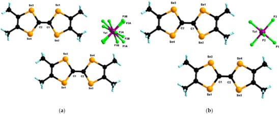
Figure 1.
Molecular structures of (TMTSF)2TaF6 at 293 K (a) and 100 K (b). For the structure at 293 K, the three independent fluorine atoms of the anion were disordered over two positions with partial refined occupancy factors of 0.61/0.39.
Depending on the purity of the starting (n-Bu4N)TaF6 and the water and oxygen content of the electrocrystallization solvent, black crystalline platelets of (TMTSF)3Ta2F10O [] occasionally form in the electrocrystallization cell, confirming the observations by Nakamura et al. from their study on the Fabre salts concerning the formation of the side crystalline product (TMTTF)3Ta2F10O []. While the electrocrystallization of TMTSF with mixtures of (n-Bu4N)TaF6 and (n-Bu4N)PF6 of three different nominal compositions (vide supra) provided variable amounts of crystalline (TMTSF)3Ta2F10O as a side product and not (TMTSF)3Ta2F11 [], the main crystalline material consisted of black crystalline needles of the Bechgaard phase (TMTSF)2(TaF6)1−x(PF6)x. The Ta/P ratio in the latter, accurately refined by X-ray analysis on a couple of single crystals from each batch, had the following values (two experiments were conducted for the 0.5/0.5 composition): 0.84/0.16 (nominal 0.8/0.2), 0.56/0/44 and 0.44/0.56 (nominal 0.5/0.5) and 0.12/0.88 (nominal 0.2/0.8) (Figures S1–S8). As the Ta/P ratio from one crystal to another within a same batch can slightly vary because of the easy formation of solid solutions thanks to the isostructurality throughout the Bechgaard series, we estimated the actual Ta/P ratio in the bulk crystalline materials through 19F NMR measurements of solutions prepared by dissolving small amounts of each material in DMSO-d6 (Figures S9–S12). The integration of the signal of PF6–, appearing as a doublet at −70 ppm with respect to the signals of fluorine atoms connected to Ta(V) provided the ratio TaF6/PF6 in the bulk material. Satisfyingly, the ratios estimated by this method were in good agreement with those obtained by the refinement of the single crystal diffraction data (Table S3). However, very precise values were difficult to obtain because although the signals of TaF6– (broad singlet at ≈41 ppm) and [Ta2F10O]2– (doublet at ≈33.7 ppm for the eight equatorial F atoms) were easily attributable [], other signals, very likely due to TaF5 solvated species, were also observed.
The substitution of PF6– by TaF6– in the structure of the Bechgaard phase provoked a steady increase of the crystalline cell volume from 709.9 Å3 for the phase 100% P [] to 741.6 Å3 for the phase 100% Ta. The analysis of the cell parameters showed that a and b increased only very slightly, i.e., by 0.033 and 0.062 Å, respectively, while the c parameter expanded much stronger, by 0.39 Å (Figure 2). This anisotropic variation was not unexpected as it is along c that the shortest intermolecular donor···anion distances were observed as weak CH···F hydrogen bonding interactions while along a and b anion···anion distances were much longer and thus these directions were relatively insensitive to the size of the anion.
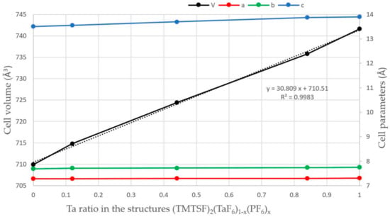
Figure 2.
Variation of the cell parameters a (red), b (green), c (blue) (Å) and cell volume (Å3) (black) in the structures (TMTSF)2(TaF6)1−x(PF6)x. The black dotted line is the linear regression curve for the variation of the cell volume.
The packing throughout the whole series was typical for the Bechgaard salts with the donors stacking along a through the axial overlap and organic-inorganic segregation along c (Figure 3 and Figure S4).
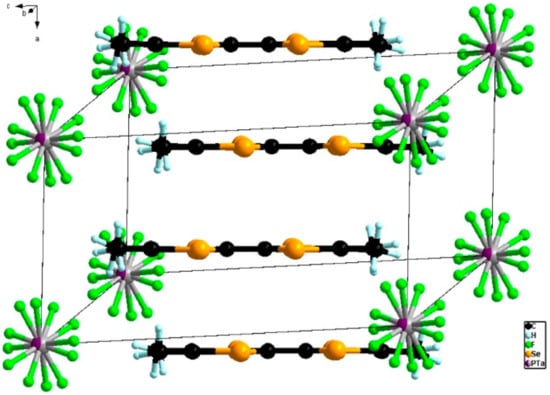
Figure 3.
Packing of TMTSF donors along a in the structure of (TMTSF)2(TaF6)0.44(PF6)0.56. The fluorine atoms were disordered over two positions.
The values of the central C=C and internal C–Se bonds throughout the series (Table S4) were typical for the Bechgaard salts, indicating a mixed valence state of TMTSF.
3.2. Radical Cation Salts of BEDT-TTF
As mentioned before, we could not find any reliable experimental details on the preparation of the claimed (BEDT-TTF)3Ta2F11 [,] salt, which, in turn, proved to be the same material as the (BEDT-TTF)3Ta2F10O we obtained by the electrocrystallization of BEDT-TTF with (n-Bu4N)2Ta2F10O []. In order to rule out any doubt on the formation of the former we decided to apply the same electrocrystallization conditions as in the case of TMTSF, namely by using alloys [(n-Bu4N)(TaF6)]1−x/[(n-Bu4N)(PF6)]x (x = 0, 0.2 and 0.8). Furthermore, as explained in the Introduction, no mixed BEDT-TTF/XF6 salts are known to date and the pure forms showed a variation of packing type and conducting properties, while keeping a 2:1 donor:anion stoichiometry. However, an inspection of the reported BEDT-TTF/XF6 (X = P, Ta) salts indicated that the orthorhombic phases β-(BEDT-TTF)2PF6 [] and δo-(BEDT-TTF)2TaF6 [] were isostructural; therefore, an orthorhombic phase with a mixed anion composition could be expected to occur. Beside the use of XF6– (X = Ta, P) anionic alloys, we also envisaged the addition of equimolar TaF6–/TaF5 mixtures in the electrocrystallization cell, assuming that condensation might take place to provide [Ta2F11]– in situ.
When the electrocrystallization experiment was performed with pure (n-Bu4N)TaF6, the already known orthorhombic δo-phase (BEDT-TTF)2TaF6 [], reminiscent of the orthorhombic β-(BEDT-TTF)2PF6 phase [], was obtained as black needles together with black platelets of (BEDT-TTF)3Ta2F10O as a side product. Curiously, the use of a nominal mixture Ta/P 0.2/0.8 provided needle-like crystals (Figure S13) of the same orthorhombic δo-phase in the group Pnna, formulated as δo-(BEDT-TTF)2(TaF6)0.43(PF6)0.57, with one independent donor and half an anion in the asymmetric unit (Figure 4). Clearly, the TaF6– anion adapted easier than PF6– to this structural type.
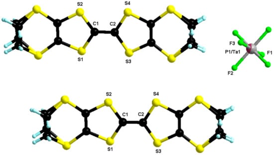
Figure 4.
Molecular structure of δo-(BEDT-TTF)2(TaF6)0.43(PF6)0.57. The two carbon atoms of both ethylene parts were disordered over two positions with refined partial occupancy factors 0.73/0.26 and 0.62/0.38.
The donors stacked on top of each other along a and interacted laterally along c with the organic-inorganic segregation being established along b (Figure 5).
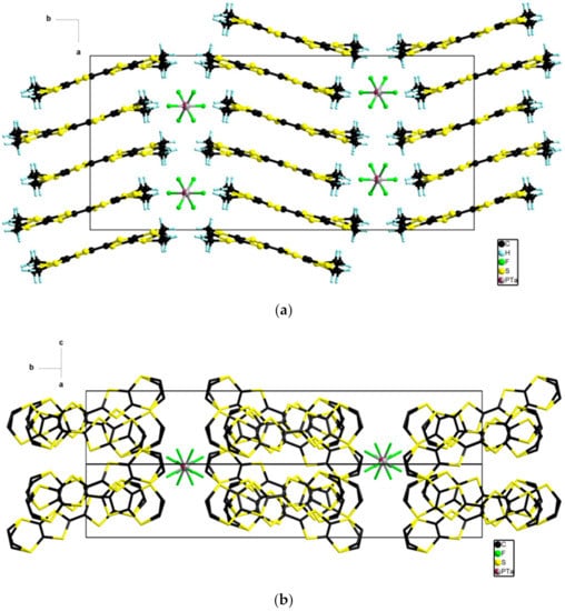
Figure 5.
View of the packing in the ab plane (a) and in the bc plane (b) in the structure of δo-(BEDT-TTF)2(TaF6)0.43(PF6)0.57.
When a reversed ratio Ta/P of 0.8/0.2 was used, the monoclinic δm-phase, group I2/a, formulated as δm-(BEDT-TTF)2(TaF6)0.94(PF6)0.06, was collected as black platelets (Figure S14). This polymorph had very similar structural characteristics with its orthorhombic congener with one independent donor and half an anion in the asymmetric unit (Figure 6) and an axial overlap of the donors along a (Figure 7).
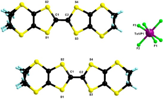
Figure 6.
Molecular structure of δm-(BEDT-TTF)2(TaF6)0.94(PF6)0.06. The two carbon atoms of the two ethylene parts were disordered over two positions with refined partial occupancy factors (0.77/0.23 and 0.63/0.37).
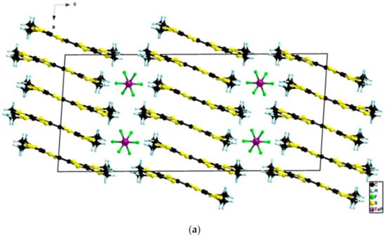
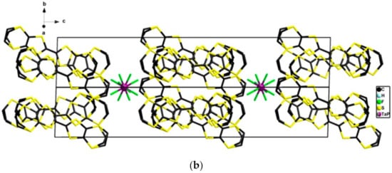
Figure 7.
View of the packing in the ac plane (a) and in the bc plane (b) in the structure of δm-(BEDT-TTF)2(TaF6)0.94(PF6)0.06.
The only notable difference, beside the morphology of the crystals, i.e. needles for the δo-phase and platelets for the δm-phase, was the inversion of the b and c axes with the organic-inorganic segregation being along c in the δm-phase (Figure 7). Moreover, the donors adopted a herringbone organization orientation across the organic-inorganic segregation axis b in the δo-phase (Figure 5) while they adopted a parallel orientation along c in the δm-phase (Figure 7). Remarkably, an excellent correlation was observed in the δm-phase for the ratio Ta/P, determined by single crystal X-ray data refinement and 19F NMR measurements of a solution obtained by dissolving the crystalline material in DMSO-d6 (Figure S15), which in both cases reached the value 0.94:0.06 (Table S3). The analysis of the central C=C and internal C–S bond lengths (Table S5) supported the mixed valence state of the donors.
A final attempt to prepare the elusive (BEDT-TTF)3Ta2F11 salt was done by using an equimolar mixture of (n-Bu4N)TaF6/TaF5 in electrocrystallization with BEDT-TTF. In these conditions, an unprecedented 1:1 phase formulated as (BEDT-TTF)2(TaF6)2·CH2Cl2 crystallized as black bars on the anode (Figure S16). The compound crystallized in the triclinic system, space group P–1, with one independent donor, one independent anion and half a molecule of CH2Cl2 in the asymmetric unit (Figure 8).
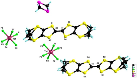
Figure 8.
Molecular structure of (BEDT-TTF)2(TaF6)2·CH2Cl2. The two carbon atoms of the two ethylene parts were disordered over two positions with refined partial occupancy factors (0.62/0.38 and 0.51/0.49).
The value of the central C=C bond length of 1.386(5) Å together with those of the internal C–S bonds ranging between 1.720(4) and 1.721(4) Å (Table S5) were in agreement with an oxidation state +1 of the donor. In the packing, the donors formed isolated dimers of a bond-over-ring type with intermolecular S···S distances in the range 3.66–3.92 Å (Figure 9).
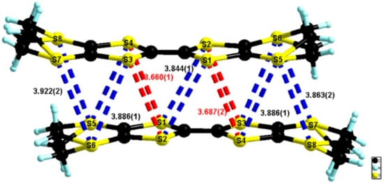
Figure 9.
Dimers of donors in the structure of (BEDT-TTF)2(TaF6)2·CH2Cl2 with an emphasis on the short intermolecular S···S contacts.
The successive dimers were separated in the stacking direction by anions and solvent molecules with no organic-inorganic segregation being observed in the packing (Figure 10).
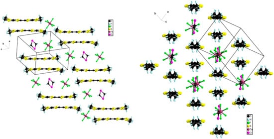
Figure 10.
Two views of the packing diagram in the structure of (BEDT-TTF)2(TaF6)2·CH2Cl2.
However, relatively short lateral S···S intermolecular distances of 3.67–3.80 Å were observed in the transversal direction (Figure 10).
In conclusion, these different trials with BEDT-TTF allowed us to prepare the first salts containing mixtures of TaF6– and PF6– anions and a new 1:1 BEDT-TTF/TaF6 phase.
3.3. Single Crystal Conductivity Measurements
3.3.1. (TMTSF)2(Ta0.8P0.2F6)-Nominal and (TMTSF)2(Ta0.2P0.8F6)-Nominal
The electrical conductivity of the needle-shaped single crystals of both compositions at room temperature was estimated to σ ≈ 100 S/cm (ρ ≈ 10 mΩ.cm) as measured in a four contacts configuration.
The temperature dependence of the resistivity was measured only for the (TMTSF)2(Ta0.2P0.8F6)-nominal corresponding with (TMTSF)2(TaF6)0.12(PF6)0.88, as determined by X-ray diffraction in a two contacts configuration. Despite a small localization below 250 K due to micro-cracks in the needle and to the resistance of the contacts, the ρ (T) curve in Figure 11 clearly shows the transition towards the spin density wave ground state around 12 K as observed in pure (TMTSF)2PF6.
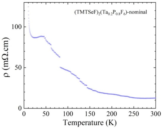
Figure 11.
Temperature dependence of the electrical resistivity of a single crystal of (TMTSF)2(Ta0.2P0.8F6)-nominal measured in two contacts.
3.3.2. (TMTSF)2(Ta0.5P0.5F6)-Nominal
Due to the small size of the needles, the resistivity of the (TMTSF)2(Ta0.5P0.5F6)-nominal could be measured only with two contacts giving a maximum value of 0.1 Ω.cm at room temperature.
3.3.3. (BEDT-TTF)2(TaF6)2·CH2Cl2
The conductivity was measured in two contacts because of large values of resistance. At room temperature, a non-ohmic behavior was observed with resistivity values varying between 2000 and 300 Ω.cm (conductivity 0.0005 to 0.0033 S/cm) for an applied voltage varying from V = 0.1 to 1 V (Figure S17). When cooling down, the activation energy estimated from the resistivity data (shown in Figure 12 and Figure S18) was around 1200 K (0.1 eV) for an applied voltage of 1 V and slightly increased for lower values of the applied voltage (up to 1500 K (0.13 eV) for V = 0.2 V). These values were compatible with a 1:1 phase and the non-ohmic character, which was sample dependent but only slightly temperature dependent, could be related to the quality of the contacts.
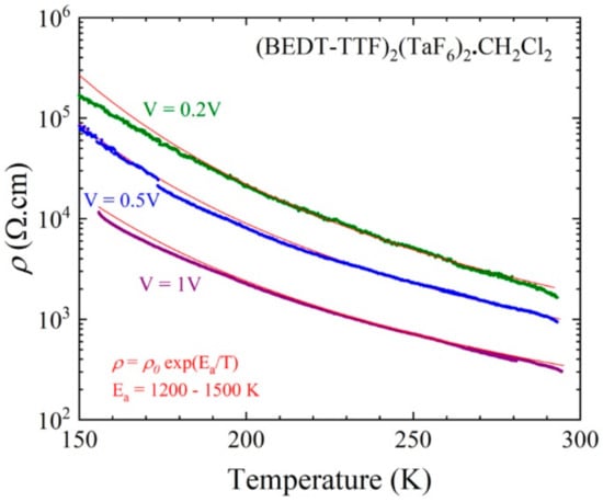
Figure 12.
Temperature dependence of the electrical resistivity of a single crystal (#3) of (BEDT-TTF)2(TaF6)2·CH2Cl2 plotted as log ρ versus T measured with different applied voltages: 0.2, 0.5 and 1 V. The red line is the linear fit to the data giving the activation energy Ea.
3.3.4. δo-(BEDT-TTF)2(Ta0.2P0.8F6)-Nominal
The electrical conductivity of the δo-(BEDT-TTF)2(Ta0.2P0.8F6)-nominal corresponding with δo-(BEDT-TTF)2(TaF6)0.43(PF6)0.57 at room temperature was estimated to σ ≈ 0.16–0.5 S/cm (ρ ≈ 2–6 Ω.cm) as measured in a four contacts configuration.
The temperature dependence of the resistivity (Figure 13) showed an activated behavior at a low temperature (below 250 K) with an activation energy of 2000 K (0.17 eV). A transition between the two semiconducting phases was observed at 296 K (as determined by the maximum of the derivative of log ρ versus 1/T), which paralleled the anomaly observed around 280–300 K in the resistivity curves of the pure δo- and δm-(BEDT-TTF)2TaF6 phases and identified as a charge ordering transition [].
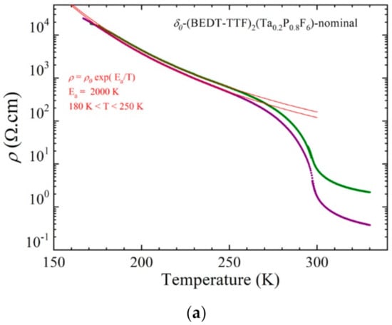
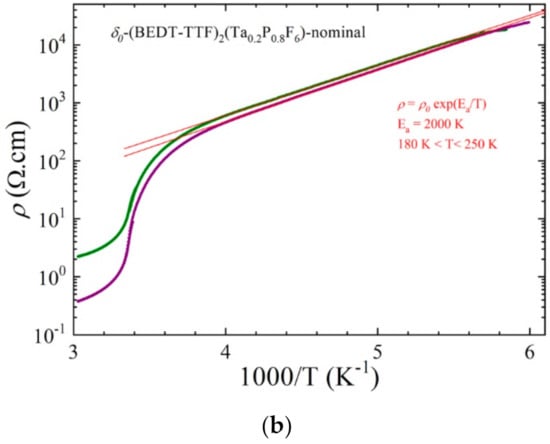
Figure 13.
Temperature dependence of the electrical resistivity of two single crystals of a δo-(BEDT-TTF)2(Ta0.2P0.8F6)-nominal plotted as log ρ versus T (a) and log ρ versus 1/T (b). The red lines are linear fit to the data giving the activation energy Ea below 250 K.
4. Conclusions
In the course of our study, we have clearly shown that the use of (n-Bu4N)TaF6 as a source of TaF6– counter-ions in TMTSF and BEDT-TTF based radical cation salts must be considered with great care as the formation of (TMTSF)3(Ta2F10O) and (BEDT-TTF)3(Ta2F10O) salts as side products readily occurs. The use of anionic mixtures [TaF6/PF6]– with nominal ratios of 0.8/0.2, 0.5/0.5 and 0.2/0.8 in electrocrystallization with TMTSF afforded Bechgaard type salts containing proportions of anions paralleling those of the nominal mixtures, which were precisely determined by accurate single crystal X-ray analyses corroborated with 19F NMR measurements indicative of the actual ratio in the bulk crystalline materials. Two such alloyed mixed valence salts were also synthesized with BEDT-TTF and also a 1:1 phase, which resulted from electrocrystallization in the presence of a TaF6–/TaF5 mixture. However, in the mixed Ta/P BEDT-TTF salts, the inclusion of TaF6– was favored over that of PF6–. Single crystal resistivity measurements were indicative of the typical conducting behavior of Bechgaard salts and showed semiconducting properties for the BEDT-TTF based materials. The results reported herein motivate further in-depth physical measurements on these mixed anionic phases in which the Ta/P ratio can be finely tuned.
Supplementary Materials
The following are available online at https://www.mdpi.com/article/10.3390/cryst11040386/s1, Figure S1: molecular structure of (TMTSF)2(TaF6)0.12(PF6)0.88, Figure S2: picture of (TMTSF)2(TaF6)0.12(PF6)0.88 needles with nested black platelets of (TMTSF)3Ta2F10O, Figure S3: molecular structure of (TMTSF)2(TaF6)0.44(PF6)0.56, Figure S4: packing of donors in the structure of (TMTSF)2(TaF6)0.44(PF6)0.56, Figure S5: molecular structure of (TMTSF)2(TaF6)0.56(PF6)0.44, Figure S6: picture of (TMTSF)2(TaF6)0.56(PF6)0.44 thin needles, Figure S7: molecular structure of (TMTSF)2(TaF6)0.84(PF6)0.16, Figure S8: picture of (TMTSF)2(TaF6)0.84(PF6)0.16 needles (left) and picture of (TMTSF)3Ta2F10O prisms, Figure S9: 19F NMR (DMSO-d6) spectrum of the crystalline material obtained by the electrocrystallization of TMTSF with a mixture (n-Bu4N)TaF6/(n-Bu4N)PF6 of a nominal composition Ta/P 0.2/0.8, Figure S10: 19F NMR (DMSO-d6) spectrum of the crystalline material obtained by the electrocrystallization of TMTSF with a mixture (n-Bu4N)TaF6/(n-Bu4N)PF6 of a nominal composition Ta/P 0.5/0.5, Figure S11: 19F NMR (DMSO-d6) spectrum of the crystalline material obtained by the electrocrystallization of TMTSF with a mixture (n-Bu4N)TaF6/(n-Bu4N)PF6 of a nominal composition Ta/P 0.5/0.5, Figure S12: 19F NMR (DMSO-d6) spectrum of the crystalline material obtained by the electrocrystallization of TMTSF with a mixture (n-Bu4N)TaF6/(n-Bu4N)PF6 of the nominal composition Ta/P 0.8/0.2, Figure S13: picture of δo-(BEDT-TTF)2(TaF6)0.43(PF6)0.57 needles, Figure S14: picture of δm-(BEDT-TTF)2(TaF6)0.94(PF6)0.06 platelets, Figure S15: 19F NMR (DMSO-d6) spectrum of the crystalline material obtained by the electrocrystallization of BEDT-TTF with a mixture (n-Bu4N)TaF6/(n-Bu4N)PF6 of a nominal composition Ta/P 0.8/0.2, Figure S16: picture of (BEDT-TTF)2(TaF6)2·CH2Cl2 thick needles, Figure S17: electrical resistivity of three single crystals of (BEDT-TTF)2(TaF6)2·CH2Cl2 at room temperature plotted as a function of the applied voltage used for a two contact measurement, Figure S18: temperature dependence of the electrical resistivity of a single crystal (#3) of (BEDT-TTF)2(TaF6)2·CH2Cl2 plotted as log ρ versus 1/T measured with different applied voltages: 0.2, 0.5 and 1 V. The red line is the linear fit to the data giving the activation energy Ea, Table S1: crystal data and structure refinement for (TMTSF)2(TaF6)0.12(PF6)0.88, (TMTSF)2(TaF6)0.44(PF6)0.56, (TMTSF)2(TaF6)0.56(PF6)0.44 and (TMTSF)2(TaF6)0.84(PF6)0.16, Table S2: crystal data and structure refinement for (TMTSF)2TaF6 (293 K and 100 K), δo-(BEDT-TTF)2(TaF6)0.43(PF6)0.57, δm-(BEDT-TTF)2(TaF6)0.94(PF6)0.06 and (BEDT-TTF)2(TaF6)2·CH2Cl2, Table S3: comparison of the proportion of phosphorus and tantalum between the inserted precursor salts used for the electrocrystallization syntheses (nominal ratio), the refined ratio in the corresponding crystallographic structures (refined ratio) and the 19F NMR integration in the TMTSF and BEDT-TTF salts, Table S4: central C=C and C–S internal bond distances (Å) of (TMTSF)2(TaF6)0.12(PF6)0.88, (TMTSF)2(TaF6)0.44(PF6)0.56, (TMTSF)2(TaF6)0.56(PF6)0.44, (TMTSF)2(TaF6)0.84(PF6)0.16 and (TMTSF)2TaF6 (293 K and 100 K), Table S5: central C=C and C–S internal bond distances (Å) of δo-(BEDT-TTF)2(TaF6)0.43(PF6)0.57, δm-(BEDT-TTF)2(TaF6)0.94(PF6)0.06 and (BEDT-TTF)2(TaF6)2·CH2Cl2.
Author Contributions
N.A. conceived and designed the experiments; C.M. prepared the materials by electrocrystallization; M.A. performed the single crystal X-ray measurements and analysis; P.A.-S. investigated the electron transport properties; N.A. wrote and/or reviewed the manuscript with contributions from all authors. All authors have read and agreed to the published version of the manuscript.
Funding
This research was partially funded in France by the National Agency for Research (ANR), Project 15-CE29-0006-01 ChiraMolCo.
Institutional Review Board Statement
Not applicable.
Informed Consent Statement
Not applicable.
Data Availability Statement
Not applicable.
Acknowledgments
This work was supported in France by the CNRS and the University of Angers. Benjamin Siegler (Plateau Astral, SFR Matrix, Université d’Angers) is thanked for help with NMR measurements.
Conflicts of Interest
The authors declare no conflict of interest. The funders had no role in the design of the study; in the collection, analyses or interpretation of data; in the writing of the manuscript or in the decision to publish the results.
References
- Yamada, J.-I. TTF Chemistry: Fundamentals and Applications of Tetrathiafulvalene; Springer: Berlin/Heidelberg, Germany, 2004. [Google Scholar]
- Jérome, D. Organic conductors: From charge density wave TTF-TCNQ to superconducting (TMTSF)2PF6. Chem. Rev. 2004, 104, 5565–5591. [Google Scholar] [CrossRef] [PubMed]
- Bendikov, M.; Wudl, F.; Perepichka, D.F. Tetrathiafulvalenes, Oligoacenenes, and Their Buckminsterfullerene Derivatives: The Brick and Mortar of Organic Electronics. Chem. Rev. 2004, 104, 4891–4945. [Google Scholar] [CrossRef] [PubMed]
- Pop, F.; Avarvari, N. Covalent non-Fused Tetrathiafulvalene-Acceptor Systems. Chem. Commun. 2016, 52, 7906–7927. [Google Scholar] [CrossRef] [PubMed]
- Avarvari, N.; Wallis, J.D. Strategies towards Chiral Molecular Conductors. J. Mater. Chem. 2009, 19, 4061–4076. [Google Scholar] [CrossRef]
- Ishiguro, T.; Yamaji, K.; Saito, G. Organic Superconductors; Springer: Berlin/Heidelberg, Germany, 1998. [Google Scholar]
- Pouget, J.-P.; Alemany, P.; Canadell, E. Donor–anion interactions in quarter-filled low-dimensional organic conductors. Mater. Horiz. 2018, 5, 590–640. [Google Scholar] [CrossRef]
- Ménard, M.; Bourbonnais, C. One-Dimensional Alternating Extended Hubbard Model at Quarter-Filling and Its Applications to Structural Instabilities of Organic Conductors. Crystals 2020, 10, 942. [Google Scholar] [CrossRef]
- Jérome, D.; Mazaud, A.; Ribault, M.; Bechgaard, K. Superconductivity in a synthetic organic conductor (TMTSF)2PF6. J. Phys. Lett. 1980, 41, L95–L98. [Google Scholar] [CrossRef]
- Bechgaard, K.; Jacobsen, C.S.; Mortensen, K.; Pedersen, H.J.; Thorup, N. The properties of five highly conducting salts: (TMTSF)2X, X = PF6-, AsF6-, SbF6-, BF4- and NO3-, derived from tetramethyltetraselenafulvalene (TMTSF). Solid State Commun. 1980, 33, 1119–1125. [Google Scholar] [CrossRef]
- Bechgaard, K.; Carneiro, K.; Rasmussen, F.B.; Olsen, M.; Rindorf, G.; Jacobsen, C.S.; Pedersen, H.J.; Scott, J.C. Superconductivity in an organic solid. Synthesis, structure, and conductivity of bis(tetramethyltetraselenafulvalenium) perchlorate, (TMTSF)2ClO4. J. Am. Chem. Soc. 1981, 103, 2440–2442. [Google Scholar] [CrossRef]
- Bourbonnais, C.; Jérome, D. Electronic confinement in organic metals. Science 1998, 281, 1155–1156. [Google Scholar] [CrossRef]
- Pouget, J.-P. Structural Aspects of the Bechgaard and Fabre Salts: An Update. Crystals 2012, 2, 466–520. [Google Scholar] [CrossRef]
- Parkin, S.S.P.; Ribault, M.; Jérome, D.; Bechgaard, K. Superconductivity in the family of organic salts based on the tetramethyltetraselenafulvalene (TMTSF) molecule: (TMTSF),X (X = CIO4, PF6, AsF6, SbF6, TaF6). J. Phys. C Solid State Phys. 1981, 14, 5305–5326. [Google Scholar] [CrossRef]
- Maaroufi, A.; Coulon, C.; Flandrois, S.; Delhaes, P.; Mortensen, K.; Bechgaard, K. Physical properties of (TMTSF)2TaF6: Influence of the anion size. Solid State Commun. 1983, 48, 555–559. [Google Scholar] [CrossRef]
- Williams, J.M.; Beno, M.A.; Sullivan, J.C.; Banovetz, L.M.; Braam, J.M.; Blackman, G.S.; Carlson, C.D.; Greer, D.L.; Loesing, D.M.; Carneiro, K. Role of monovalent anions in organic superconductors. Phys. Rev. B 1983, 28, 2873–2876. [Google Scholar] [CrossRef]
- Traetteberg, O.; Kriza, G.; Lenoir, C.; Huang, Y.-S.; Batail, P.; Jérôme, D. Dielectric constant and dielectric relaxation of the pinned spin-density wave in the alloys (TMTSF)2(AsF6)1-x(SbF6)x. Synth. Met. 1993, 56, 2785–2790. [Google Scholar] [CrossRef]
- Traetteberg, O.; Kriza, G.; Lenoir, C.; Huang, Y.-S.; Batail, P.; Jérôme, D. Damping of the spin-density-wave phase mode by defect scattering. Phys. Rev. B 1994, 49, 409–412. [Google Scholar] [CrossRef]
- Kim, Y.M.; Mihály, G.; Jiang, H.W.; Grüner, G. The Low Temperature Spin Density Wave Transport: Effects of Magnetic Field in (TMTSF)2PF6 and Disorder in (TMTSF)2X’s. Synth. Met. 1995, 70, 1287–1290. [Google Scholar] [CrossRef]
- Thorup, N.; Rindorf, G.; Soling, H.; Johannsen, I.; Mortensen, K.; Bechgaard, K. Structural Studies of some (TMTSF)2X Compounds. J. Phys. Coll. 1983, 44, C3-1017–C3-1020. [Google Scholar] [CrossRef]
- Mori, T. Organic Conductors with Unusual Band Fillings. Chem. Rev. 2004, 104, 4947–4969. [Google Scholar] [CrossRef]
- Coronado, E.; Day, P. Magnetic Molecular Conductors. Chem. Rev. 2004, 104, 5419–5448. [Google Scholar] [CrossRef]
- Urayama, H.; Yamochi, H.; Saito, G.; Nozawa, K.; Sugano, T.; Kinoshita, M.; Sato, S.; Oshima, K.; Kawamoto, A.; Tanaka, J. A New Ambient Pressure Organic Superconductor Based on BEDT-TTF with Tc Higher than 10 K (Tc = 10.4 K). Chem. Lett. 1988, 17, 55–58. [Google Scholar] [CrossRef]
- Kini, A.M.; Geiser, U.; Wang, H.H.; Carlson, K.D.; Williams, J.M.; Kwok, W.K.; Vandervoort, K.G.; Thompson, J.E.; Stupka, D.L. A new ambient-pressure organic superconductor, κ-(ET)2Cu[N(CN)2]Br, with the highest transition temperature yet observed (Inductive Onset Tc = 11.6 K, Resistive Onset = 12.5 K). Inorg. Chem. 1990, 29, 2555–2557. [Google Scholar] [CrossRef]
- Komatsu, T.; Nakamura, T.; Matsukawa, N.; Yamochi, H.; Saito, G.; Ito, H.; Ishiguro, T.; Kusunoki, M.; Sakaguchi, K. New ambient-pressure organic superconductors based on BEDT-TTF, Cu, N(CN)2 and CN with Tc = 10.7 K and 3.8 K. Solid State Commun. 1991, 80, 843–847. [Google Scholar] [CrossRef]
- Saito, G.; Yamochi, H.; Nakamura, T.; Komatsu, T.; Ishiguro, T.; Nogami, Y.; Ito, Y.; Mori, H.; Oshima, K.; Nakashima, M.; et al. Overview of organic superconductor κ-(BEDT-TTF)2[Cu[(NCS)2] and its related materials. Synth. Met. 1991, 42, 1993–1998. [Google Scholar] [CrossRef]
- Miyagawa, K.; Kanoda, K.; Kawamoto, A. NMR Studies on Two-Dimensional Molecular Conductors and Superconductors: Mott Transition in κ-(BEDT-TTF)2X. Chem. Rev. 2004, 104, 5635–5653. [Google Scholar] [CrossRef] [PubMed]
- Kobayashi, H.; Kato, R.; Mori, T.; Kobayashi, A.; Sasaki, Y.; Saito, G.; Inokuchi, H. Crystal Structure of κ-(BEDT-TTF)2PF6. Chem. Lett. 1983, 12, 759–762. [Google Scholar] [CrossRef]
- Kobayashi, H.; Mori, T.; Kato, R.; Kobayashi, A.; Sasaki, Y.; Saito, G.; Inokuchi, H. Transverse Conduction and Metal-Insulator Transition in β-(BEDT-TTF)2PF6. Chem. Lett. 1983, 12, 581–584. [Google Scholar] [CrossRef]
- Nogami, Y.; Mori, T. Unusual 2kF CDW state with enhanced charge ordering in β-(BEDT-TTF)2AsF6 and PF6. J. Phys. IV Fr. 2002, 12, 233–234. [Google Scholar]
- Leung, P.C.W.; Beno, M.A.; Blackman, G.S.; Coughlin, B.R.; Miderski, C.A.; Joss, W.; Crabtree, G.W.; Williams, J.M. Structure of Semiconducting 3,4;3’,4’-Bis(ethylenedithio)-2,2’,5,5’-tetrathiafulvalene–Hexafluoroarsenate (2:1), (BEDT-TTF)2AsF6, (C10H10S8)2AsF6. Acta Crystallogr. Sect. C 1984, 40, 1331–1334. [Google Scholar] [CrossRef]
- Laversanne, R.; Amiell, J.; Delhaes, P.; Chasseau, D.; Hauw, C. A metal-insulator phase transition close to room temperature: (BEDT-TTF)2SbF6 and (BEDT-TTF)2AsF6. Solid State Commun. 1984, 52, 177–181. [Google Scholar] [CrossRef]
- Kawamoto, T.; Kurata, K.; Mori, T.; Kumai, R. Charge Ordering Transitions of the New Organic Conductors δm- and δo-(BEDT-TTF)2TaF6. Magnetochemistry 2017, 3, 14. [Google Scholar] [CrossRef]
- Kawamoto, T.; Kurata, K.; Mori, T. A New Dimer Mott Insulator: κ-(BEDT-TTF)2TaF6. J. Phys. Soc. Jpn. 2018, 87, 083703. [Google Scholar] [CrossRef]
- Lenoir, C.; Boubekeur, K.; Batail, P.; Canadell, E.; Auban, P.; Traetteberg, O.; Jérome, D. (TMTSF)3Ta2F11: Synthesis, Structural Chemistry, Electronic Structure and Physical Properties. Synth. Met. 1991, 42, 1939–1942. [Google Scholar] [CrossRef]
- Acrivos, J.V.; Hughes, H.P.; Parkin, S.S.P. ESR study of optically enhanced phase transition in (BEDT-TTF)3Ta2F11. J. Chem. Phys. 1987, 86, 1780–1788. [Google Scholar] [CrossRef]
- Acrivos, J.V. Dynamic Phenomena in Organic Metal (BEDT-TTF)3Ta2F11. Mol. Cryst. Liq. Cryst. 1996, 284, 411–417. [Google Scholar] [CrossRef]
- Mroweh, N.; Mézière, C.; Allain, M.; Auban-Senzier, P.; Canadell, E.; Avarvari, N. Conservation of structural arrangements and 3:1 stoichiometry in a series of crystalline conductors of TMTTF, TMTSF, BEDT-TTF, and chiral DM-EDT-TTF with the oxo-bis[pentafluorotantalate(V)] dianion. Chem. Sci. 2020, 11, 10078–10091. [Google Scholar] [CrossRef]
- Iwase, F.; Sugiura, K.; Furukawa, K.; Nakamura, T. Electronic Properties of a TMTTF-Family Salt, (TMTTF)2TaF6: New Member Located on the Modified Generalized Phase-Diagram. J. Phys. Soc. Jpn. 2009, 78, 104717. [Google Scholar] [CrossRef]
- Pop, F.; Zigon, N.; Avarvari, N. Main-Group-Based Electro-and Photoactive Chiral Materials. Chem. Rev. 2019, 119, 8435–8478. [Google Scholar] [CrossRef]
- Mroweh, N.; Mézière, C.; Pop, F.; Auban-Senzier, P.; Alemany, P.; Canadell, E.; Avarvari, N. In Search of Chiral Molecular Superconductors: κ-[(S,S)-DM-BEDT-TTF]2ClO4 Revisited. Adv. Mater. 2020, 32, 2002811. [Google Scholar] [CrossRef]
- Pop, F.; Auban-Senzier, P.; Frąckowiak, A.; Ptaszyński, K.; Olejniczak, I.; Wallis, J.D.; Canadell, E.; Avarvari, N. Chirality Driven Metallic versus Semiconducting Behavior in a Complete Series of Radical Cation Salts Based on Dimethyl-Ethylenedithio-Tetrathiafulvalene (DM-EDT-TTF). J. Am. Chem. Soc. 2013, 135, 17176–17186. [Google Scholar] [CrossRef]
- Pop, F.; Auban-Senzier, P.; Canadell, E.; Avarvari, N. Anion size control of the packing in the metallic versus semiconducting chiral radical cation salts (DM-EDT-TTF)2XF6 (X = P, As, Sb). Chem. Commun. 2016, 52, 12438–12441. [Google Scholar] [CrossRef]
- Sheldrick, G.M. Crystal structure refinement with SHELX. Acta Cryst. 2015, 71, 3–8. [Google Scholar]
- Sheldrick, G.M. SHELXT-Integrated space-group and crystal-structure determination. Acta Cryst. 2015, A71, 3–8. [Google Scholar] [CrossRef]
- Farrugia, L.J. WinGX and ORTEP for Windows: An update. J. Appl. Cryst. 2012, 45, 849–854. [Google Scholar] [CrossRef]
- CrysAlisPro 1.171.38.41 or 1.171.40.45 (Rigaku Oxford Diffraction, 2015–2019)-Empirical absorption correction using spherical harmonics, implemented in SCALE3 ABSPACK scaling algorithm.
- Han, Y.-K.; Son, K.-I.; Kang, W.; Hong, C.S.; Noh, D.-Y. Fabrication of (TMTSF)2PF6 thin crystals in a confined electrode. Synth. Met. 2007, 157, 492–496. [Google Scholar] [CrossRef]
Publisher’s Note: MDPI stays neutral with regard to jurisdictional claims in published maps and institutional affiliations. |
© 2021 by the authors. Licensee MDPI, Basel, Switzerland. This article is an open access article distributed under the terms and conditions of the Creative Commons Attribution (CC BY) license (https://creativecommons.org/licenses/by/4.0/).